Embed Size (px)
Citation preview

Bull Earthquake Eng (2013) 11:1061–1081DOI 10.1007/s10518-012-9418-z
ORIGINAL RESEARCH PAPER
Role of wall panel connections on the seismicperformance of precast structures
Fabio Biondini · Bruno Dal Lago ·Giandomenico Toniolo
Received: 21 October 2011 / Accepted: 22 December 2012 / Published online: 18 January 2013© Springer Science+Business Media Dordrecht 2013
Abstract Past seismic events, including the 2009 L’Aquila earthquake and the 2012 Emiliaearthquake, clearly demonstrated the inadequacy of the current design approach for theconnection system of the cladding wall panels of precast buildings. To clarify this problemthe present paper investigates the seismic behaviour of a traditional precast structural frame forindustrial buildings with a new type of connection system of cladding panels. This systemconsists of a statically determined pendulum arrangement of panels, each supported withtwo hinges to the structure, one at the top and one at the bottom, so to have under seismicaction a pure frame behaviour where the wall panels are masses without stiffness. Addingmutual connections between the panels, the wall cladding panels become part of the resistingstructure, leading to a dual frame/wall system or to a wall system depending on the stiffness ofthe connections. The seismic behaviour of this structural assembly is investigated for differentdegrees of interaction between frame and panels, as well as for an enhanced solution withdissipative connections. The results of nonlinear static (pushover) analyses and nonlineardynamic analyses under recorded and artificial earthquakes highlight the role of the wall panelconnections on the seismic behaviour of the structural assembly and show the effectivenessof the dual frame/wall system with dissipative connections between panels.
Keywords Seismic design · Concrete structures · Precast structures ·Cladding wall panels · Connection devices
1 Introduction
In the tradition of precast concrete structures in Southern Europe, typical frame structureswith cantilever columns and large floor spans have been widely used for industrial andcommercial buildings since the sixties. For this type of buildings the use of large and heavy
F. Biondini (B) · B. Dal Lago · G. TonioloDepartment of Civil and Environmental Engineering, Politecnico di Milano,Piazza L. da Vinci, 32, 20133 Milan, Italye-mail: [email protected]
123
1062 Bull Earthquake Eng (2013) 11:1061–1081
precast concrete cladding panels is quite common. They have been and still are consideredas “non structural” members of the building, acting as seismic masses without stiffnessand designed with local calculations, neglecting any contribution to the overall structuralbehaviour.
Past seismic events, including the 2009 L’Aquila earthquake and 2012 Emilia earthquake,clearly demonstrated the inadequacy of this approach to design the connections of the wallpanels. Surveys on the effects of the 2009 L’Aquila earthquake are reported in Menegotto(2009) and Colombo and Toniolo (2012a). Many collapses of cladding panels due to under-designed connections have been reported. While the typical frame is very flexible and highenergy dissipation can be achieved at large drifts, the cladding-frame connections were stat-ically undetermined but not designed for overall horizontal actions.
A comprehensive literature review on seismic performance of cladding systems in build-ings can be found in NIST GCR 96-681 (1995). In particular, the problem of cladding-frameinteraction has been studied in Palsson et al. (1984) and Henry and Roll (1986), showingthat such interaction can dramatically change the seismic response. A proposal to exploit thecooperation of large cladding panels to reduce the seismic response through energy dissipa-tion has been presented in Pinelli et al. (1995). The idea of exploiting the rocking motion ofstructural wall panels with dissipating couplers has been explored by Priestley et al. (1999)within the PRESSS program. Devices with dissipative capacities based on mechanisms ofyielding or friction and designed to make mutual connections between wall panels have beeninvestigated in Shultz et al. (1994) and Iqbal et al. (2007).
Colombo and Toniolo (2012b) presented a systematic framing of the problem, indicatingthree possible solutions to avoid panel collapses due to the failure of their connections. Thesesolutions include:
(a) The adoption of a statically determined support system that makes the panels independentfrom the motion of the structure or allows a rigid motion of the panels;
(b) The adoption of an integrated support system adequately proportioned that makes thepanels integral part of the resisting structure.
The present study starts from a particular arrangement of the statically determined solution(a), with a pendulum support system of vertical panels, consisting of two hinges applied one atthe top and one at the bottom of each panel, and shows the effectiveness of mutual connectionsadded between the panels so to integrate them into the resisting structural system as in theintegrated solution (b). The seismic behaviour of this structural assembly is investigated fordifferent degrees of interaction between frame and panels, as well as for an enhanced solutionwith dissipative connections (Biondini et al. 2012a). The results of nonlinear static (pushover)analyses and nonlinear dynamic analyses under recorded and artificial earthquakes highlightthe role of the wall panel connections on the seismic behaviour of the structural assembly andshow the effectiveness of the dual frame/wall system with dissipative connections betweenpanels.The case study stands within the scope of a wider problem that will engage for some yearsthe researchers in the field of prefabrication to find adequate solutions. After more than15 years of experimental and analytical research at European level, the achieved knowledgeled to well defined criteria and reliable technical and normative documents for the design ofprecast frame structures (Biondini and Toniolo 2009, 2010). The problem of a proper designof the connections between the structural elements of the construction has been recentlyinvestigated within the European research project SAFECAST “Performance of InnovativeMechanical Connections in Precast Building Structures under Seismic Conditions” (FP7-SME-2007-2, Grant agreement No. 218417, 2009) with the involvement of 16 partners from
123
Bull Earthquake Eng (2013) 11:1061–1081 1063
the European countries more exposed to seismic risk (Toniolo 2012; Biondini et al. 2012b;Negro et al. 2012). The involvement of cladding panels in the resisting system of precastindustrial buildings will be investigated within the scope of the recently started Europeanresearch project SAFECLADDING “Improved fastening systems of cladding wall panels ofprecast buildings in seismic zones” (FP7-SME-2012, Grant agreement No. 314122, 2012).
2 The prototype
The investigated structural prototype is a one-storey precast frame building of 40.5 × 25.0 mof dimensions in plan, made of two lines of five columns 7.0 m high and spaced by 10.0 m.The roof is made of five transverse shed beams supporting ribbed elements. Under seismiccondition the dead loads of the roof are related to:
– roof elements (including permanent finishings) = 2.8 kN/m2;– shed beams (average weight) = 17.5 kN/m;– longitudinal beams (panel supporting) = 3.2 kN/m;
that lead to a vertical action of 600 kN on each of the 3 + 3 middle columns and 410 kN oneach of the 2+2 end columns. All the columns have a square cross-section with side width of60 cm and are reinforced with 12 φ 20 mm longitudinal bars corresponding to the minimumreinforcement ratio of 1 % given by Eurocode 8 (CEN-EN 1998-1 2004). The steel Class isB450C. The concrete Class is C45/55, with elastic modulus equal to 30 GPa.
A set of 16 + 16 vertical wall panels are placed along the two major sides of the building,with dimensions 2.5 × 8.0 m and an equivalent concrete thickness of 12 cm, leading toa weight of 3.0 kN/m2. The panels are placed at the base on the foundation beam with acentral hinged support that allows their free pendulum movement within the limits of the jointallowance left between the foundation beam and the panel. At the height of 7.08 m the panelsare connected to the supporting beam with a central hinge. In this configuration the connectionsystem represents a statically determined solution. In the integrated solution the panels arejointed between them by means of three connections placed in the adjacent sides at 1/4, 2/4and 3/4 of the support height. Figure 1 shows the view of one cladding wall with the indicationof the supports and panel connections. Figure 2 shows the equilibrium of the forces of oneinternal panel (Fig. 2a), with connections at both sides, and of an end panel (Fig. 2b), withconnections at one side, respectively. The equilibrium conditions between the horizontal (H)and vertical (V) components of the forces in the supports and the forces F1 and F2 in thepanel connections can be obtained from the geometrical dimensions b and h as follows forboth the internal panel:
H = (F1 + 2F2) b/h
V = 0
and the external panel:
H = (F1 + 2F2) b/2h
V = (F1 + 2F2) /2 = Hh/b
These equations, applied to the total set of panels (with F1 ≈ 0.8F2, as shown in Clause 3),provide the resistance of the connections required to sustain the horizontal action H associatedto the limit state to be fulfilled.
123

1064 Bull Earthquake Eng (2013) 11:1061–1081
Fig. 1 View of the cladding wall system
Fig. 2 Static scheme for in-planeequilibrium of a central andb side panels underhorizontal loading
3 Linear elastic analysis
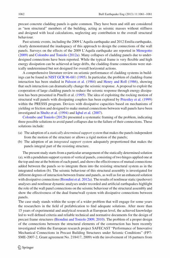
The analysis of the structural system is carried out by means of a finite element model withbeam elements for columns and shell elements for panels (Fig. 3). A first series of linearelastic static analyses are performed on this model by applying at the top of the columns anhorizontal force of 1,000 kN that corresponds to a ratio of about 1/3 of the competent roofand wall weights computed as follows:
2.8 × 40.0 × 25.0 = 2,800
5 × 17.5 × 25.0 = 2,187
3.2 × 2 × 40.0 = 256
3.0 × 12.0 × 8.0/2 = 1,440
W = 6,683 kN/2=3,341 kN
where the cladding walls are considered extended to the whole perimeter less two openingsof 5.0 m each.
With reference to the degree of reciprocal connection between the panels, the followingtwo limit cases are studied: absence of connections (stiffness k = 0), with structural responsegiven only by the columns, and perfectly rigid connections (stiffness k = ∞), with structuralresponse given almost only by the wall panels. Intermediate cases are also studied withdifferent values of the elastic stiffness k of the connections.
123
Bull Earthquake Eng (2013) 11:1061–1081 1065
Fig. 3 Finite element model of the cladding wall system
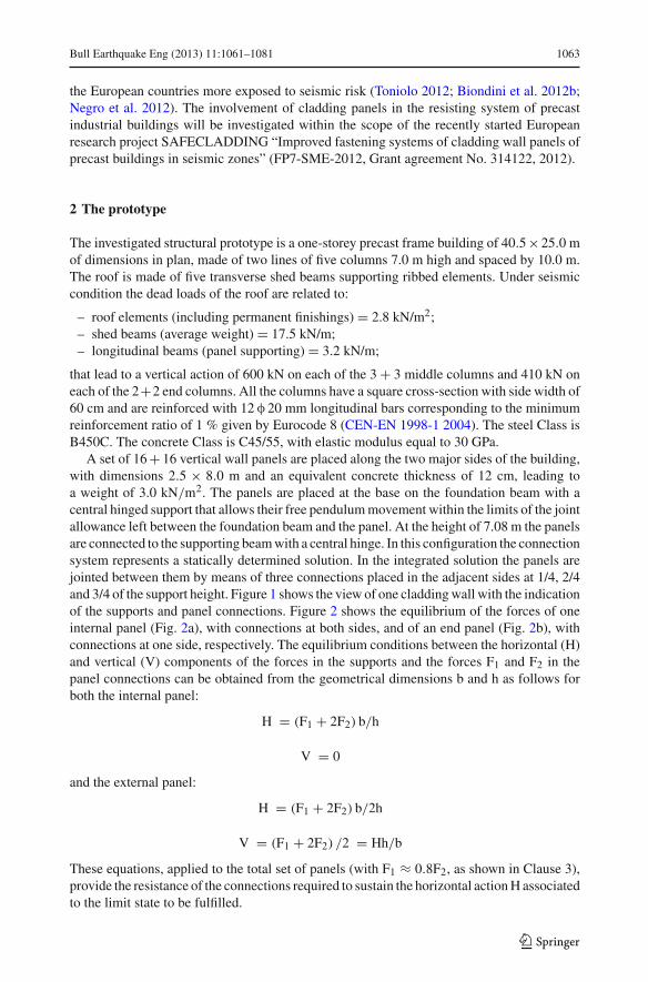
Fig. 4 Statically determined system: deformed shape of the structure (dtop = 73.0 mm)
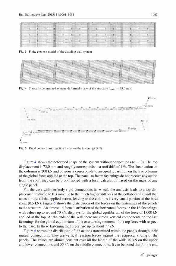
Fig. 5 Rigid connections: reaction forces on the fastenings (kN)
Figure 4 shows the deformed shape of the system without connections (k = 0). The topdisplacement is 73.0 mm and roughly corresponds to a roof drift of 1 %. The shear action onthe columns is 200 kN and obviously corresponds to an equal repartition on the five columnsof the global force applied at the top. The panel-to-beam fastenings do not receive any actionfrom the roof: they can be proportioned with a local calculation based on the mass of anysingle panel.
For the case with perfectly rigid connections (k = ∞), the analysis leads to a top dis-placement reduced to 0.3 mm due to the much higher stiffness of the collaborating wall thattakes almost all the applied action, leaving to the columns a very small portion of the baseshear (0.5 kN). Figure 5 shows the distribution of the forces on the fastenings of the panelsto the structure. An almost uniform distribution of the horizontal forces on the 16 fastenings,with values up to around 70 kN, displays for the global equilibrium of the force of 1,000 kNapplied at the top. At the ends of the wall there are strong vertical components on the lastfastenings for the global equilibrium of the overturning moment of the top force with respectto the base. In these fastening the forces rise up to about 77 kN.
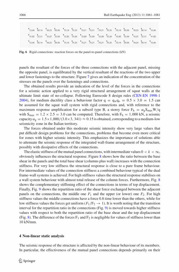
Figure 6 shows the distribution of the actions transmitted within the panels through theirmutual connections. They are vertical reaction forces against the reciprocal sliding of thepanels. The values are almost constant over all the length of the wall: 70 kN on the upperand lower connections and 55 kN on the middle connections. It can be noted that for the end
123
1066 Bull Earthquake Eng (2013) 11:1061–1081
Fig. 6 Rigid connections: reaction forces on the panel-to-panel connections (kN)
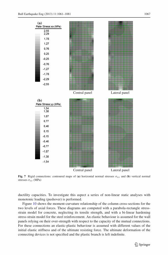
panels the resultant of the forces of the three connections with the adjacent panel, missingthe opposite panel, is equilibrated by the vertical resultant of the reactions of the two upperand lower fastenings to the structure. Figure 7 gives an indication of the concentration of thestresses on the panels over the fastenings and connections.
The obtained results provide an indication of the level of the forces in the connectionsfor a seismic action applied to a very rigid structural arrangement of squat walls at theultimate limit state of no-collapse. Following Eurocode 8 design rules (CEN-EN 1998-12004), for medium ductility class a behaviour factor q = qwqo = 0.5 × 3.0 = 1.5 canbe assumed for the squat wall system with rigid connections and, with reference to themaximum response amplification for a subsoil type B, a storey force Fh = αgSmaxW/qwith Smax = 1.2 × 2.5 = 3.0 can be computed. Therefore, with Fh = 1,000 kN, a seismiccapacity αg = 1.5×1,000/(3.0×3, 341) ≈ 0.15 is obtained, corresponding to a medium-lowseismicity zone in the Italian territory.
The forces obtained under this moderate seismic intensity show very large values thatput difficult design problems for the connections, problems that become even more criticalfor zones with higher seismic intensity. This emphasizes the importance of solutions ableto attenuate the seismic response of the integrated wall-frame arrangement of the structure,possibly with dissipative effects of the connections.
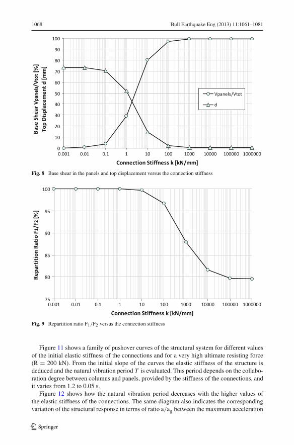
The elastic stiffness of the mutual panel connections, with intermediate values 0 < k < ∞,obviously influences the structural response. Figure 8 shows how the ratio between the baseshear in the panels and the total base shear (columns plus wall) increases with the connectionstiffness. For very low stiffness the structural response is close to a pure frame behaviour.For intermediate values of the connection stiffness a combined behaviour typical of the dualframe-wall systems is achieved. For high stiffness values the structural response stabilises ona wall system behaviour with almost total release of the column forces. Furthermore, Fig. 8shows the complementary stiffening effect of the connections in terms of top displacement.Finally, Fig. 9 shows the repartition ratio of the shear force exchanged between the adjacentpanels on the connections, the middle one F1 and the upper (or lower) one F2. For highstiffness values the middle connections have a force 0.8 time lower than the others, while forlow stiffness values the forces get uniform (F1/F2 → 1). It is worth noting that the transitioninterval for the repartition ratio in the connections (Fig. 9) is moved towards higher stiffnessvalues with respect to both the repartition ratio of the base shear and the top displacement(Fig. 8). The difference of the forces F1 and F2 is negligible for values of stiffness lower than10 kN/mm.
4 Non-linear static analysis
The seismic response of the structure is affected by the non-linear behaviour of its members.In particular, the effectiveness of the mutual panel connections depends primarily on their
123
Bull Earthquake Eng (2013) 11:1061–1081 1067
(a)
Central panel Lateral panel
(b)
Central panel Lateral panel
Fig. 7 Rigid connections: contoured maps of (a) horizontal normal stresses σxx and (b) vertical normalstresses σyy (MPa)
ductility capacities. To investigate this aspect a series of non-linear static analyses withmonotonic loading (pushover) is performed.
Figure 10 shows the moment-curvature relationship of the column cross-sections for thetwo levels of axial forces. These diagrams are computed with a parabola-rectangle stress-strain model for concrete, neglecting its tensile strength, and with a bi-linear hardeningstress-strain model for the steel reinforcement. An elastic behaviour is assumed for the wallpanels relying on their over-strength with respect to the capacity of the mutual connections.For these connections an elastic-plastic behaviour is assumed with different values of theinitial elastic stiffness and of the ultimate resisting force. The ultimate deformation of theconnecting devices is not specified and the plastic branch is left indefinite.
123
1068 Bull Earthquake Eng (2013) 11:1061–1081
Fig. 8 Base shear in the panels and top displacement versus the connection stiffness
Fig. 9 Repartition ratio F1/F2 versus the connection stiffness
Figure 11 shows a family of pushover curves of the structural system for different valuesof the initial elastic stiffness of the connections and for a very high ultimate resisting force(R = 200 kN). From the initial slope of the curves the elastic stiffness of the structure isdeduced and the natural vibration period T is evaluated. This period depends on the collabo-ration degree between columns and panels, provided by the stiffness of the connections, andit varies from 1.2 to 0.05 s.
Figure 12 shows how the natural vibration period decreases with the higher values ofthe elastic stiffness of the connections. The same diagram also indicates the correspondingvariation of the structural response in terms of ratio a/ag between the maximum acceleration
123

Bull Earthquake Eng (2013) 11:1061–1081 1069
θ
Fig. 10 Bending moment-curvature relationship of the column cross-sections
Fig. 11 Pushover curves for R = 200 kN
a and the peak ground acceleration ag, computed from the elastic response spectrum givenby Eurocode 8 for subsoil type B. A large increase of the seismic force can be noted inthe solution with wall panels integrated in the structural assembly, with values of the ratioa/ag that initially increases with the connection stiffness from 1.3 to 3.0 and then decreaseto 1.8 for the case of rigid connections. This response factor does not consider the energydissipation possibly offered by the structural system.
123

1070 Bull Earthquake Eng (2013) 11:1061–1081
Fig. 12 Parameters of the dynamic response
Fig. 13 Push-over curves for k = 10 kN/mm
Figure 13 shows that the pushover curve of the structural system is limited to the levelcorresponding to the different possible strengths of the connections. It is worth noting that theshear ratio taken by the wall panels in the elastic stage (see Fig. 8) decreases progressivelyafter the yielding of the connections with the development of their plastic deformation untilthe yielding of the columns, as shown in Fig. 14. From these results it is clear that, if theconnections have sufficient plastic deformation capacity, the choice of their strength levelcan influence the energy dissipation capacity and properly regulate the structural responsewith reference to the intensity of the seismic action expected on site. An example of this
123

Bull Earthquake Eng (2013) 11:1061–1081 1071
Fig. 14 Plastic repartition of base shear for k = 100 kN/mm
Fig. 15 Components of adissipative connection device(SPAV)
regulation will be presented in the next section devoted to nonlinear dynamic analysis of theprototype.
5 Non-linear dynamic analysis
Non-linear dynamic analyses of the prototype are carried out considering a dissipative con-nection device tested at the Laboratory for material testing of Politecnico di Milano for SPAVCompany, Martignacco, Italy (Ferrara et al. 2011). The “SPAV” connection is made of twosteel T shaped parts, obtained from the cut of an IPE profile, that are fixed to the adjacentpanels in special cavities and jointed with two lateral bolted steel plates, as shown in Fig. 15.The length of the bolt holes gives the limit to the reciprocal slide between the parts. The tight-ening torque given to the bolts, controlled by dynamometric wrench, activates the frictionbetween the plates determining the slip resistance. Two brass sheets are interposed between
123
1072 Bull Earthquake Eng (2013) 11:1061–1081
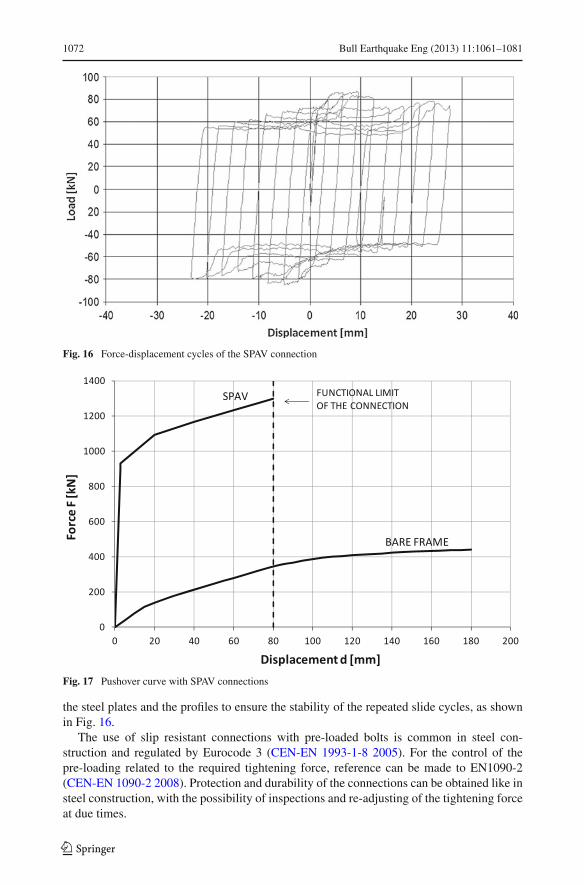
Fig. 16 Force-displacement cycles of the SPAV connection
Fig. 17 Pushover curve with SPAV connections
the steel plates and the profiles to ensure the stability of the repeated slide cycles, as shownin Fig. 16.
The use of slip resistant connections with pre-loaded bolts is common in steel con-struction and regulated by Eurocode 3 (CEN-EN 1993-1-8 2005). For the control of thepre-loading related to the required tightening force, reference can be made to EN1090-2(CEN-EN 1090-2 2008). Protection and durability of the connections can be obtained like insteel construction, with the possibility of inspections and re-adjusting of the tightening forceat due times.
123
Bull Earthquake Eng (2013) 11:1061–1081 1073
(a)
(b)
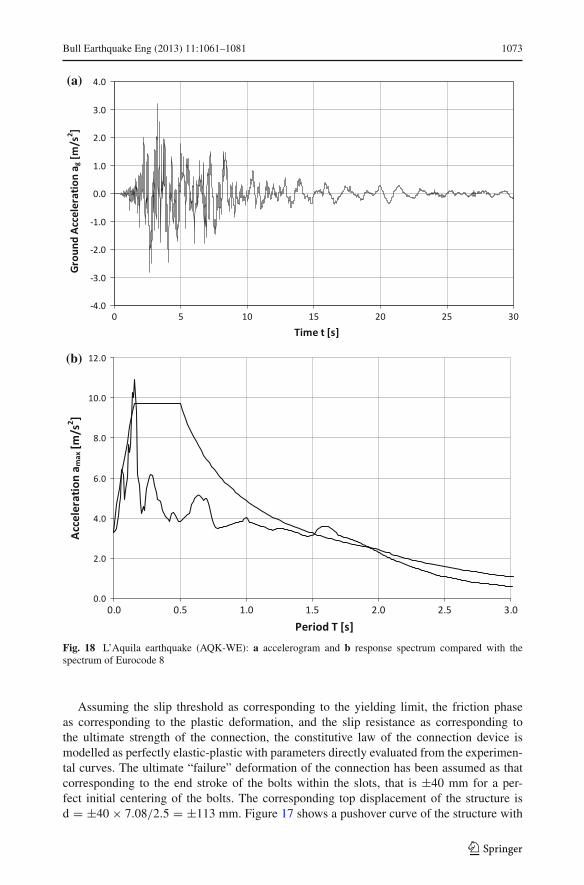
Fig. 18 L’Aquila earthquake (AQK-WE): a accelerogram and b response spectrum compared with thespectrum of Eurocode 8
Assuming the slip threshold as corresponding to the yielding limit, the friction phaseas corresponding to the plastic deformation, and the slip resistance as corresponding tothe ultimate strength of the connection, the constitutive law of the connection device ismodelled as perfectly elastic-plastic with parameters directly evaluated from the experimen-tal curves. The ultimate “failure” deformation of the connection has been assumed as thatcorresponding to the end stroke of the bolts within the slots, that is ±40 mm for a per-fect initial centering of the bolts. The corresponding top displacement of the structure isd = ±40 × 7.08/2.5 = ±113 mm. Figure 17 shows a pushover curve of the structure with
123

1074 Bull Earthquake Eng (2013) 11:1061–1081
(a)
(b)
Fig. 19 Set of artificial earthquakes: a one accelerogram from the set (SC), and b response spectra of the setof accelerograms compared with the model of Eurocode 8
SPAV connections computed with the elastic-plastic model based on an initial stiffness of600 kN/mm, a slip resistance of 60 kN and a “functional” stroke limit of ±25 mm.
The dynamic non linear analyses are performed with a Takeda model (Takeda et al. 1970)for the columns, the elastic-plastic model described above for SPAV connections, and a linearelastic model for the panels.
The analyses are performed under a recorded accelerogram of the 2009 L’Aquila earth-quake (AQK-WE) with PGA = 0.32 g, and ten artificial synthetic accelerograms (SC) com-patible with the response spectrum given by Eurocode 8 for subsoil type B and scaled to
123

Bull Earthquake Eng (2013) 11:1061–1081 1075
Fig. 20 Displacement time-histories under L’Aquila earthquake (AQK-WE)
PGA = 0.32 g. Figures 18 and 19 show these accelerograms and their elastic response spec-tra compared to the Eurocode 8 spectrum. It is worth noting that the scanty compatibilityof the response spectrum of L’Aquila earthquake with the Eurocode 8 standard spectrum,due to its poor content of frequencies, could lead to a weaker impact on the actual structuralresponse.
The different response of the three structural configurations (statically determined, inte-grated and dissipative) under L’Aquila earthquake (AQK-WE) is shown in terms of vibratorycurves in Fig. 20. The diagram at the top gives the displacement time history response fora zero connection stiffness (pure frame structure), with large storey drifts; the diagram atthe bottom shows the structural response with rigid connections (wall structure), with smallstorey drifts and high connection forces; the diagram in the middle shows the structuralresponse with dissipative SPAV connections (dissipative structure), with intermediate storeydrifts and limited connection forces. The same analyses are performed for the set of ten arti-ficial accelerograms. Figure 21 shows the vibratory curves of the system under one artificialaccelerogram from the set (SC, Fig. 19a).
The strong effectiveness of the connections can be noticed in lowering the maximumstorey drift of the statically determined system from 80 to 4 mm and 0.6 mm underL’Aquila earthquake, and from 80 to 6 mm and 0.8 mm under the artificial accelerogram,for SPAV connections and rigid connections, respectively. The large increase of vibra-tion frequencies of the structural responses of the integrated systems can also be noted.
123

1076 Bull Earthquake Eng (2013) 11:1061–1081
Fig. 21 Displacement time-histories under an artificial earthquake (SC, Fig. 19a)
In particular, the response with rigid connections corresponds to a pure elastic behaviour ofa stiff wall system.
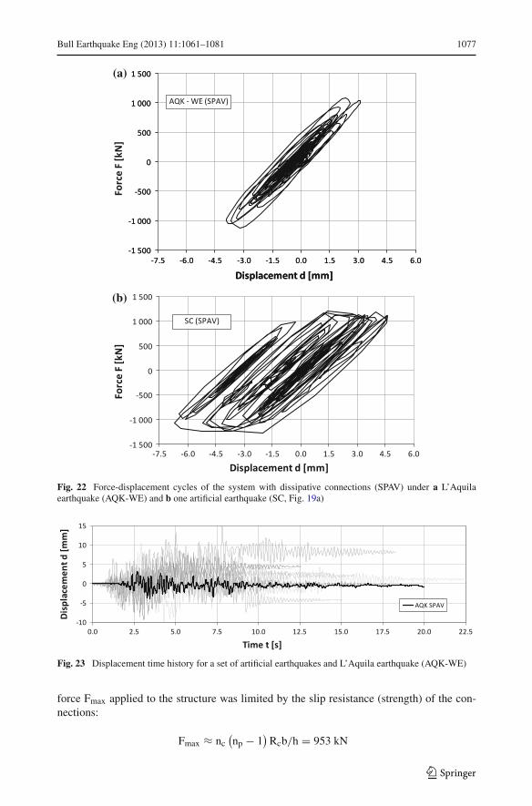
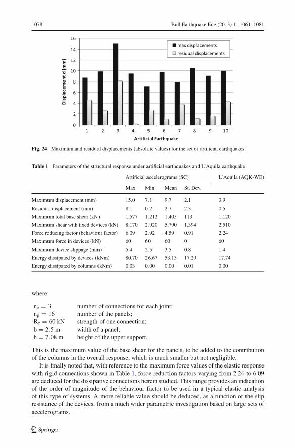
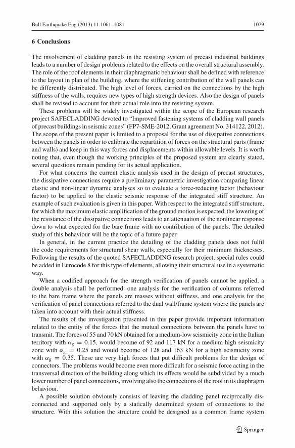
The residual displacements of the integrated structure with dissipative connections indicatethat an inelastic slide occurred in the connections and, therefore, the friction mechanismworked in dissipating energy. This is more evident for the artificial accelerograms that have,with their full content of frequencies, a stronger impact on the structure. The measure of theenergy dissipation can be deduced from the force-displacement diagrams shown in Fig. 22,where the area within the cycles is much wider for the artificial accelerogram. The vibratorycurves corresponding to the whole set of artificial accelerograms are compared in Fig. 23for the configuration with dissipative devices. Figure 24 shows the absolute values of themaximum and residual displacements associated to the set of artificial earthquakes. The valuesof representative parameters of the structural response for the set of artificial earthquakes andL’Aquila earthquake are listed in Table 1.
It is worth noting that the maximum displacements reached with the artificial accelero-grams are much higher than with the recorded one, and are characterized by a relatively lowdispersion. A mean residual displacement of 2.71 mm is expected under the artificial earth-quakes, with a large scatter due to the variability of time history of each accelerogram. Theenergy dissipation is mainly provided by the nonlinear behaviour of the devices, while thecolumns remain almost linear elastic. In all the studied cases the maximum total horizontal
123
Bull Earthquake Eng (2013) 11:1061–1081 1077
(a)
(b)
Fig. 22 Force-displacement cycles of the system with dissipative connections (SPAV) under a L’Aquilaearthquake (AQK-WE) and b one artificial earthquake (SC, Fig. 19a)
Fig. 23 Displacement time history for a set of artificial earthquakes and L’Aquila earthquake (AQK-WE)
force Fmax applied to the structure was limited by the slip resistance (strength) of the con-nections:
Fmax ≈ nc(np − 1
)Rcb/h = 953 kN
123
1078 Bull Earthquake Eng (2013) 11:1061–1081
Fig. 24 Maximum and residual displacements (absolute values) for the set of artificial earthquakes
Table 1 Parameters of the structural response under artificial earthquakes and L’Aquila earthquake
Artificial accelerograms (SC) L’Aquila (AQK-WE)
Max Min Mean St. Dev.
Maximum displacement (mm) 15.0 7.1 9.7 2.1 3.9
Residual displacement (mm) 8.1 0.2 2.7 2.3 0.5
Maximum total base shear (kN) 1,577 1,212 1,405 113 1,120
Maximum shear with fixed devices (kN) 8,170 2,920 5,790 1,394 2,510
Force reducing factor (behaviour factor) 6.09 2.92 4.59 0.91 2.24
Maximum force in devices (kN) 60 60 60 0 60
Maximum device slippage (mm) 5.4 2.5 3.5 0.8 1.4
Energy dissipated by devices (kNm) 80.70 26.67 53.13 17.29 17.74
Energy dissipated by columns (kNm) 0.03 0.00 0.00 0.01 0.00
where:
nc = 3 number of connections for each joint;np = 16 number of the panels;Rc = 60 kN strength of one connection;b = 2.5 m width of a panel;h = 7.08 m height of the upper support.
This is the maximum value of the base shear for the panels, to be added to the contributionof the columns in the overall response, which is much smaller but not negligible.
It is finally noted that, with reference to the maximum force values of the elastic responsewith rigid connections shown in Table 1, force reduction factors varying from 2.24 to 6.09are deduced for the dissipative connections herein studied. This range provides an indicationof the order of magnitude of the behaviour factor to be used in a typical elastic analysisof this type of systems. A more reliable value should be deduced, as a function of the slipresistance of the devices, from a much wider parametric investigation based on large sets ofaccelerograms.
123
Bull Earthquake Eng (2013) 11:1061–1081 1079
6 Conclusions
The involvement of cladding panels in the resisting system of precast industrial buildingsleads to a number of design problems related to the effects on the overall structural assembly.The role of the roof elements in their diaphragmatic behaviour shall be defined with referenceto the layout in plan of the building, where the stiffening contribution of the wall panels canbe differently distributed. The high level of forces, carried on the connections by the highstiffness of the walls, requires new types of high strength devices. Also the design of panelsshall be revised to account for their actual role into the resisting system.
These problems will be widely investigated within the scope of the European researchproject SAFECLADDING devoted to “Improved fastening systems of cladding wall panelsof precast buildings in seismic zones” (FP7-SME-2012, Grant agreement No. 314122, 2012).The scope of the present paper is limited to a proposal for the use of dissipative connectionsbetween the panels in order to calibrate the repartition of forces on the structural parts (frameand walls) and keep in this way forces and displacements within allowable levels. It is worthnoting that, even though the working principles of the proposed system are clearly stated,several questions remain pending for its actual application.
For what concerns the current elastic analysis used in the design of precast structures,the dissipative connections require a preliminary parametric investigation comparing linearelastic and non-linear dynamic analyses so to evaluate a force-reducing factor (behaviourfactor) to be applied to the elastic seismic response of the integrated stiff structure. Anexample of such evaluation is given in this paper. With respect to the integrated stiff structure,for which the maximum elastic amplification of the ground motion is expected, the lowering ofthe resistance of the dissipative connections leads to an attenuation of the nonlinear responsedown to what expected for the bare frame with no contribution of the panels. The detailedstudy of this behaviour will be the topic of a future paper.
In general, in the current practice the detailing of the cladding panels does not fulfilthe code requirements for structural shear walls, especially for their minimum thicknesses.Following the results of the quoted SAFECLADDING research project, special rules couldbe added in Eurocode 8 for this type of elements, allowing their structural use in a systematicway.
When a codified approach for the strength verification of panels cannot be applied, adouble analysis shall be performed: one analysis for the verification of columns referredto the bare frame where the panels are masses without stiffness, and one analysis for theverification of panel connections referred to the dual wall/frame system where the panels aretaken into account with their actual stiffness.
The results of the investigation presented in this paper provide important informationrelated to the entity of the forces that the mutual connections between the panels have totransmit. The forces of 55 and 70 kN obtained for a medium-low seismicity zone in the Italianterritory with αg = 0.15, would become of 92 and 117 kN for a medium-high seismicityzone with αg = 0.25 and would become of 128 and 163 kN for a high seismicity zonewith αg = 0.35. These are very high forces that put difficult problems for the design ofconnectors. The problems would become even more difficult for a seismic force acting in thetransversal direction of the building along which its effects would be subdivided by a muchlower number of panel connections, involving also the connections of the roof in its diaphragmbehaviour.
A possible solution obviously consists of leaving the cladding panel reciprocally dis-connected and supported only by a statically determined system of connections to thestructure. With this solution the structure could be designed as a common frame system
123

1080 Bull Earthquake Eng (2013) 11:1061–1081
following the traditional approach, with much lower forces and with the attention focusedmore on the storey drift rather than on the column strength. Special connections would beneeded to allow the very large displacements expected under earthquake conditions. Thesolution suggested by the present study employs on the contrary a statically undeterminedsystem of connections with limited strength, calibrated on the slip resistance of specialconnectors up to the requested level, in expectation of a reduced response due to the dis-sipative capacities of the connections. It seems a promising way, based on very simplelow cost devices, which addition could be largely compensated by the reduction of thecolumn size.
Acknowledgments This study has been developed within the scope of the EU Seventh FrameworkProgramme FP7-SME-2012: SAFECLADDING—Improved Fastening Systems of Cladding Wall Panels ofPrecast Buildings in Seismic Zones, Grant agreement No. 314122, 2012.
References
Biondini F, Toniolo G (2009) Probabilistic calibration and experimental validation of seismic design criteriafor one storey concrete frames. J Earthq Eng 13:426–462
Biondini F, Toniolo G (2010) Experimental research on behaviour of precast structures. L’Industria Italianadel Cemento 854:74–79
Biondini F, Dal Lago B, Toniolo G (2012a) Seismic behaviour of precast buildings with cladding panels. In:15th World conference on earthquake engineering (15WCEE), Lisbon, Portugal, Sept 24–28, 2012
Biondini F, Titi A, Toniolo G (2012b) Pseudodynamic tests and numerical simulation on a full scale prototype ofa multi-storey precast structure. In: 15th World conference on earthquake engineering (15WCEE), Lisbon,Portugal, Sept 24–28, 2012
CEN-EN 1998-1 (2004) Eurocode 8: design of structures for earthquake resistance—part 1: general rules,seismic actions and rules for buildings. European Committee for Standardization, Brussels
CEN-EN 1993-1-8 (2005) Eurocode 3: design of steel structures—part 1–8: Design of joints. EuropeanCommittee for Standardization, Brussels
CEN-EN 1090-2 (2008) Execution of steel structures and aluminium structures—part 2: technical requirementsfor steel structures. European Committee for Standardization, Brussels
Colombo A, Toniolo G (2012a) Precast concrete structures: the lesson learnt from L’Aquila earthquake. StructConcr J FIB 13(2):71–139
Colombo A, Toniolo G (2012b) Problems of seismic design of the cladding panels of precast buildings. In:New Zealand society for earthquake engineering (NZSEE) annual conference, Christchurch, New Zealand,Apr 13–15, 2012
Craig J, Goodno B, Pinelli J, Moor C (1992) Modeling and evaluation of ductile cladding connection systems forseismic response attenuation in buildings. In: 10th World conference on earthquake engineering (10WCEE),vol 7, pp 4183–4188, Madrid, Spain, July 19–24, 1992
Ferrara L, Felicetti R, Toniolo G, Zenti C (2011) Friction dissipative devices for cladding panels in precastbuildings. Eur J Environ Civil Eng 15(9):1319–1338
Henry RM, Roll F (1986) Cladding-frame interaction. J Struct Eng ASCE 112(4):815–834Iqbal A, Pampanin S, Buchanan A, Palermo A (2007) Improved seismic performance of LVL post-tensioned
walls coupled with UFP devices. In: 8th Pacific conference on earthquake engineering, Singapore, Dec5–7, 2007
Menegotto M (2009) Observations on precast concrete structures of industrial buildings and warehouses.Progettazione sismica 3:149–153 (Special issue on the 2009 L’Aquila earthquake)
Negro P, Bournas DA, Molina FJ (2012) Pseudodynamic testing of the SAFECAST three-storey precastbuilding. In: 15th World conference on earthquake engineering (15WCEE), Lisbon, Portugal, Sept 24–28,2012
NIST GCR, 96–681 (1995) Literature review on seismic performance of building cladding systems. NationalInstitute of Standards and Technology, United States Department of Commerce, USA
Palsson H, Goodno BJ, Graig JI, Will KM (1984) Cladding influence on dynamics response of tall buildings.Earthq Eng Struct Dyn 12(2):215–228
Pinelli J-P, Craig JI, Goodno BJ (1995) Energy-based seismic design of ductile cladding systems. J Struct Eng121(3):567–578
123

Bull Earthquake Eng (2013) 11:1061–1081 1081
Priestley MJN, Sritharan S, Conley JR, Pampanin S (1999) Preliminary results and conclusions from thePRESSS five-story precast concrete test building. PCI J 44(6):42–67
Shultz AE, Magana RA, Trados MK, Huo X (1994) Experimental study of joint connections in precast concretewalls. In: 5th U.S. National conference on earthquake engineering, Chicago, IL, USA, July 10–14, 1994
Takeda T, Sozen MA, Nielsen NN (1970) Reinforced concrete response to simulated earthquakes. J Struct DivASCE 96(12):2557–2573
Toniolo G (2012) SAFECAST project: European research on seismic behaviour of the connections of precaststructures. In: 15th World conference on earthquake engineering (15WCEE), Lisbon, Portugal, Sept 24–28,2012
123