Embed Size (px)
Citation preview

Role of the consulting engineer in hydroand pumped storage systems
G.B. Murdoch, B.Sc.(Eng.), C.Eng., M.I.Mech.E.
Indexing terms: Engineering administration & management, Power systems & plant
Abstract: From the earliest stages in the development of a hydroelectric scheme, economists, planners andengineers must work closely together. Within the engineering group, collaboration is even more essential and itwill be most effective if civil, mechanical and electrical engineers have a sympathetic understanding of eachother's technical problems. This collaboration should continue from the initial planning stages to the commis-sioning and testing of the complete installation. The paper discusses some of the problems which may arise atthe various stages in the design and construction of a scheme. It is assumed that a decision has been taken tobuild a scheme of a certain ultimate capacity, and the paper considers the economic and technical planning, forexample, to determine the rating and number of machines together with the programme for the construction ofthe civil works and installation of plant. For the project design, many aspects call for joint studies involvingcivil, mechanical and electrical engineers, for example, the head and rating, to determine the type of turbine andthe approximate speed. Hydraulic design requires close collaboration between the three disciplines, to deter-mine an economic system for the range of loading conditions to be imposed on the plant. The preparation oftechnical specifications proceeds concurrently in all three disciplines, for which a continuous exchange of infor-mation is essential, and the adjudication of tenders must take into account the interaction of plant and civilworks. Detailed design proceeds after the placing of contracts, when further refinements are made. At thecommissioning stage, close collaboration is essential, during the first filling of the hydraulic system and sub-sequent tests involving the hydraulic and electrical transmission systems, to prove satisfactory performance.
1 Introduction
The design and implementation of a hydroelectric scheme,be it conventional or pumped storage, calls for a particu-larly close degree of collaboration between the three engi-neering disciplines, civil, mechanical and electrical. Thetechnological demands of such a scheme cannot, however,be neatly divided up into civil, mechanical and electricalpackages and allocated to the appropriate consultant andcontractor. In practice, there are two major interdisciplin-ary exercises: water and electricity.
In conventional hydro, the water exercise normallyinvolves civil engineering in the impounding of water bydams, the conveyance of that water by tunnel and pipelineto a power station and the disposal downstream of thespent water, while in pumped storage the spent water isusually retained in a closed hydraulic system (Fig. 1). Itinvolves mechanical engineering in the management of thewater by gates and valves, and the abstraction of energyfrom that water by means of water turbines. The civil/mechanical interface is traditionally taken to occur at theturbine, but the various components of the water systemare interactive to such a degree that they must be studiedand developed as a single entity. Under steady conditions,the hydraulic power available to the turbine will dependon the relative water levels at the dam and in the tailrace,the friction and shock losses on the hydraulic system andthe quantity of water available. In transient conditions, sayon sudden loss of load followed by overspeeding of theturbine, the surge in the low-pressure tunnel and the waterhammer in the high-pressure pipeline will depend tovarying extents on mechanical parameters, such as gover-nor closing time, generating set inertia and turbine specificspeed (Fig. 2). Thus, the conceptual design must be a singleintegral exercise, in which civil and mechanical engineersmust both participate fully. When the work moves on tothe detailed design and preparation of specifications, the
Paper 3309A (M3, M4), first received 1 lth May and in revised form 20th June 1984The author is an associate of Merz and McLellan, Amberley, Killingworth, Newcas-tle upon Tyne NE12 ORS, England
two disciplines will be occupied more with the objectivesand means of construction, and at that stage much of theireffort will be self-contained. However, there will still besubstantial liasion at the various interfaces, as betweengenerating plant and power station building, between pipe-line and turbine supply, as well as in the overall program-ming of the entire construction.
Fig. 1 Cruachan pumped storageUpper reservoir and dam, Loch Awe and lower control works4 x 100 MW under 343 m
IEE PROCEEDINGS, Vol. 131, Pt. A, No. 6, AUGUST 1984 383

The electricity exercise may be considered to extendfrom the shaft coupling, where the generator receives
The prime role of the consulting engineer lies in thesetting up and joint operation of an experienced team, the
700-
Fig. 2 Dinorwig pumped storageCalculated and observed transients following generator trip6 x 300 MW under 530 m
calculatedx site measurement
mechanical power from the turbine, through transmissionand distribution and ultimately to the consumer. However,from the generator terminals the electricity exercise followsmuch the same technological practice as that from thermalor nuclear generating plant; it is not a specifically hydromatter. Perhaps the most significant electrical developmentin relation to water power is in the area of the long-distance high-voltage transmission needed to conveypower from remote areas with huge hydro potential tourban and industrial areas of high demand. In hydro work,the generator must not only be matched to transmissionand load requirements, but must also accommodate anumber of parameters arising from the hydraulic design ofthe turbine, notably:
(a) speed(b) overspeeds and runaway speed (rotor)(c) axial hydraulic load (thrust bearing)(d) top cover diameter (stator bore)
as well as providing sufficient rotational inertia for stabil-ity of governing in isolated operation, and to cater for themost severe transient conditions.
The major interface lies between the water system andthe electricity system. The generating set, which utiliseswater to produce electricity, is the link. Together with itsancillary equipment, the set itself involves many interfaces.These can lead to absurdities, such as a turbine with'mechanical' bearings coupled to a generator with 'electri-cal' bearings, which is supported by 'civil' foundations. It isin such areas that engineers must display sufficient under-standing of each other's problems to ensure optimum solu-tions (Fig. 3). The joint objective should be to provide thecommunity with an economic, reliable and flexible sourceof energy at reasonable cost.
Fig. 3 Model of underground machine hall at Kariba6 x 100 MW under 86 m
preparation of designs and specifications, the engineeringand supervision of the works and the testing and commis-sioning of the completed scheme, followed by such adviceas his client may require after handing-over The team maybe a loose association of independent firms, usually withone taking the lead, or, alternatively, a formally consti-tuted joint venture.
The role of the consulting engineer in the project man-agement of these projects is dealt with elsewhere in thisspecial issue. The present paper is confined to engineeringaspects.
2 Stages of a project
Projects in the hydro and related fields, like others, may bedeveloped in stages comprising the following:
(a) prefeasibility study(b) feasibility study(c) project report (sometimes referred to as the 'execu-
tive project report')(d) conditions of contract and specifications(e) preparation and issue of enquiry documents(/) tender evaluations(g) contract administration and engineering(h) testing and inspection(i) site construction and commissioning(j) winding up of contracts.
Because of the large-scale nature, both in physical and dis-ciplinary aspects, of hydro projects, the first three stagesoften involve consultants in a number of fields outside the
384 IEE PROCEEDINGS, Vol. 131, Pt. A, No. 6, AUGUST 1984
three main disciplines. These may include consultants ineconomics, finance, fisheries, agriculture, transport,tourism, medical/hygiene, meteorology and specialist legal.
Once the consultant's feasibility study has laid down thebroad parameters of the project, and these have beenaccepted by the client and any other interested bodies, theproject report explores the options available to execute theproject outlined. After this stage, decisions must be madeby the client and consulting engineer on the best way toplace contracts for the plant. While a turnkey contractcovering both civil works and mechanical and electricalplant is sometimes adopted, because of political or loanconsiderations, it is more usual to place a number ofseparate contracts; for the mechanical and electrical work,perhaps four or five major ones and ten or so smaller ones.The consulting engineer is experienced in handling such anumber of contracts and arranging the interfaces betweenthem. There is no doubt that this procedure results notonly in a wider and more satisfactory choice of plant, butin a cheaper project. Moreover, it enables the phasing ofcontracts and installation to be carried out more eco-nomically, and the plant details available from the initialcontracts can be used to optimise the specification of laterones.
3 Rating of machines
The settlement of the rating of a proposed machineinvolves, on the one hand, a recognition of technologicallimits, which for a given head may be regarded as impos-ing a maximum upon the possible choice of size, and onthe other hand, the ascertainment, among many feasiblechoices, of the one which is the economic optimum. It isimportant to keep the distinction in mind, especially inconsidering the interacting effects of civil, mechanical andelectrical engineering, because it sometimes happens thatwhat is thought by one department to be an absolute limitturns out to be an expression of the other department'sview as to the most economic. Even in a case where, forexample, the civil engineer pronounces that a furtherextension of station dimensions would not be permissible,because it would encroach upon inferior rock strata, it is amatter for the plant designer to consider whether somemodification to the design concept would allow the necess-ary increase in size to be achieved in some way that wouldmake the inferior strata easier for his civil colleague to dealwith; for example, by changing the axis of the machinesfrom vertical to horzontal, in the case of an undergroundstation.
The planner of the station on his part, having in mindthe general economics of the operation, may well have sug-gested a machine rating which would allow a build-up ofstation size closely in line with expected load growth,thereby avoiding premature expenditure and unnecessaryinterest charges; this rating may, however, lead to a largernumber of machines than the site could accommodate,either within the bounds of practical possibility or withinreasonable economic limits. In such a case, the eventualrating might just as easily be found to be determined bythe maximum number of machines which could be accom-modated. For example, where the load growth suggests six100 MW machines, a size of four 150 MW machines mightbe selected for this reason.
The establishment of economic optima is a matterrequiring considerable experience. Over the years, the con-sulting engineer will have accumulated extensive data onprices and rates for generating plant and civil works. Thesedata enable him to optimise the leading parameters of a
hydroelectric scheme, and ensure that major uncertaintiesare resolved before specifications are prepared and issuedto tenderers. The estimating of generating plant costs isparticularly difficult in hydroelectric work, where, in addi-tion to the usual commercial and political uncertainties,the engineer may have to work at any point in a range ofoutputs from 100 kW to 600 MW, a range of heads from 2m to 2000 m, and a range of speeds from 44 rev/min to1500 rev/min. A realistic appraisal of the effects on price ofinflation and recession is essential at the present time. Abank of recent actual tender prices provides the only reli-able basis for assessing these factors. Published indices,industrial or governmental, can be seriously misleading.When the variations of machine costs with parametershave been assessed, there remains the other side of thebalance sheet, which is concerned with the variations inthe cost of civil engineering work which would accompanya choice of, for example, different speed of machine, i.e.changes in setting and, therefore, depth of excavation andaccompanying changes in diameter. Here, the cost dataneed to be taken with some reserve, especially in the pre-sence of geological features upon which judgment has tobe exercised. Practical civil engineering problems of largeexcavation cannot always be dealt with on the simple basisof the cost per cubic metre.
The rating of individual machines, and not the number,may on the other hand be limited to that which can bedeveloped in the space allowed by existing construction.Such a situation can arise when new plant is beinginstalled in an existing power station, i.e. replacing obsol-ete plant or utilising space left for extensions, or whenmachine centres are determined by the spacing of tunnelsor penstocks constructed earlier. It is important to takeadvantage of developing technique, which may allow theplant in the later stages of a station to be significantlygreater in output than the plant for which the space hadoriginally been allocated.
Close integration of civil engineering design withmachine design is sometimes made difficult by the phasingof a project, which may originally be conceived mainly forpurposes unconnected with power, but if the civil engi-neering is not sufficiently far-sighted, it may be found that,for example, the centres between the buttresses of a dam,by dictating the spacing of machines installed later, lead toa less economic disposition of plant than might otherwisehave been secured, and there is a certain amount offreedom in the selection of dam buttresses, if the desir-ability of some varation is recognised at a sufficiently earlystage. This is one aspect of the need for association of theplant engineering with civil engineering at the earliest pos-sible stage, even where the plant installation is to bedeferred or the possibility of its eventual installation is indoubt.
4 Installation programme
The programme for the installation of plant will initiallybe based by the planner on expected load growth. It must,however, take account of a number of technical consider-ations, which may indicate the need to install somemachines earlier than the load requires.
For example, construction costs may be considerablyaffected if the time interval between machines is too longor too short; if too long, it may involve running down ofthe labour force in the interval between successive install-ations, and building it up again for the next round of activ-ity, an expensive procedure in relation to terminal costs,especially in remote sites, and one which can result in a
IEE PROCEEDINGS, Vol. 131, Pt. A, No. 6, AUGUST 1984 385

loss of continuity in the experience of the labour force ontwo successive installations. If the interval is too short, itcould require the duplication of specialist labour, which ismore expensive not only because of terminal costs, butbecause of the provision that may need to be made foradditional accommodation. An interval of four to sixmonths is often convenient for large plant; it allowswelders to proceed from one spiral to the next, or windersto move from one stator to the next, and accords with theperiods required for the main civil operations. In thismatter, also, it is important to question the validity of pre-conceived notions; for example, that concrete work, orspiral welding, cannot be achieved in a shorter time thanhas been customary. While most engineering operationscan be found to have a particular duration which is mosteconomic, considering operation individually, it may wellbe that the overall economics of a project require, in someparts, the use of nonoptimum working procedures, forexample, in ensuring that certain stages of a project arecompleted between recurrent natural phenomena such asriver floods.
For a number of reasons, civil, mechanical and electri-cal, it is often advantageous to install machines in pairs.The layout of auxiliary plant, drainage and dewateringequipment, draft-tube and spiral-casing access can bearranged most economically on a two-machine basis. Twogenerators are sometimes paired with one generator set-uptransformer and one high-voltage circuit breaker forreasons of economy. Furthermore, where long transmis-sion lines are involved, it may be necessary to have twomachines available for line-charging, in order to commis-sion the station.
Thus, both technical and economic considerations maywell suggest the installation of machines in pairs, with aninterval of four to six months between individualmachines, the interval between one pair and the next beingdetermined by load growth considerations.
5 Project design
Many aspects of project design call for joint studies involv-ing civil, mechanical and electrical engineers. The head andrating determine the type of turbine and the approximatespeed. Closer determination of speed involves balancingthe civil cost of deeper setting, and hence more excavationin surface stations, against plant saving on higher-speedmachines. The normal and runaway speeds of the gener-ator derive from the turbine characteristics, and the thrustbearing will have to sustain, in addition to the weight ofthe rotating parts, the maximum hydraulic thrust exertedon the turbine runner; where the thrust is not additive, onthe other hand, it cannot be taken in relief of thrust design.The fact that power station cranes must extend over theplant adequately for initial erection and subsequent main-tenance, and possess the necessary capacity and height oflift, determines the upper dimensions and the structuraldesign of the power station. In all these studies, the designtends to progress from one discipline to another in alogical sequence.
The problem of speed regulation, on the other hand,necessitates parallel consideration of the civil, mechanicaland electrical engineering aspects.
The civil engineer must consider the pressure changeswhich result from change of flow through the turbines dueto governor action. These may occur as water hammerand, in the case of long tunnels, as surge-chamber swings.Water hammer can be reduced, at some cost, by increasingthe size of conduits not protected by surge chambers.
Unsafe negative water hammer may necessitate lowering aconduit at critical points in the profile.
The electrical system engineer lays down the maximumvariation in frequency to be permitted following a specifiedsudden change of load. The permissible variations in fre-quency, or indeed voltage, vary a good deal from onesystem to another, with some electricity authorities havingvery high standards of supply, which impose severe limi-tations on the variations that can be permitted on theirsystems. In other parts of the world, especially in thedeveloping countries, more substantial variation can bepermitted, which eases the design of the hydraulic system.At the same time, the system engineer indicates theminimum inertia constant which will satisfy system stabil-ity requirements. This may be considerably more than the'natural' inertia inherent in the generator, in which case itfalls to the generator engineer to design and cost amachine of adequate inertia, which may even require theaddition of a flywheel. In cases where electrical stability ismarginal, it may be necessary to employ braking resistors,which are switched rapidly in and out of circuit.
The governor provides the link between the electricalsystem requirements for frequency control and stability,the rotational energy of the machine and the kinetic energyof the water. The electronic governor has largely replacedthe mechanical type, and close collaboration is neededbetween the mechanical engineer, who must co-ordinate allthe governing functions, and the electronic engineer, whounderstands the complex circuitry involved.
The following data provide the starting point for thespecification of the turbine governor and turbine-regulating system:
(a) conduit diameter optimised for cost/losses(b) hydraulic profile(c) permissible frequency variations(d) minimum acceptable machine inertia(e) effect on conduit cost of increase in diameter or
design pressure(/) effect on generator cost of increase in inertia.
For load-off conditions, the variation of pressure andspeed-rise with time is investigated, for a range of conduitdiameters and machine inertia. These variations will indi-cate a range of technically practicable solutions, which canthen be costed to enable an economic choice to be made. Itis usually found unjustifiable to consider pressure risesabove about 40%, as these in turn tend to counteract thereduction in speed-rise resulting from a shorter closingtime. Larger conduit diameters do not normally offer aneconomic solution, even when the decrease in losses istaken into account. Higher machine inertia, on the otherhand, usually offers an economic and effective contributionto the reduction of speed variations. This is particularly soin the case of large, slow machines, which tend to have ahigh 'natural' inertia constant, and in small, horizontal-shaft sets, where a relatively large separate flywheel can befitted without excessive extra cost.
In conventional hydro, load-on conditions are usuallyless onerous, although in small systems, at an early stage ofdevelopment, fed by only one or two machines, relativelysevere demands may have to be met, sometimes under dif-ficult conditions with long flat pipeline profiles. Hereagain, machine inertia is usually found to offer an effectiveand economic means of meeting system requirements.Large pressure drops tend to cancel out any advantagewhich might be expected from rapid governor opening.
In pumped storage practice, rapid response to systemdemands is usually essential, so load-on conditions may
386 IEE PROCEEDINGS, Vol. 131, Pt. A, No. 6, AUGUST 1984

well dictate conduit diameters larger than those arrived atfrom a conventional study, based on the assessment ofconstruction cost against operational losses.
6 Preparation of detailed technical specifications
To avoid delays, it is essential that civil, mechanical andelectrical engineers should work concurrently in the prep-aration of specifications and drawings for issue to ten-derers. This means, however, that assumptions have to bemade and accepted as the basis for a lot of work, on theunderstanding that refinements in detail will be necessaryafter the placing of contracts. The civil engineer mustdesign the power station structure on the basis of generallayout drawings prepared by the plant engineer. Suchdrawings should give the leading dimensions of the gener-ating plant and the building, but cannot at this stageinclude precise dimensions of foundation requirements.
Tunnels, surge chambers and penstocks may bedesigned with more certainty, except in the case of pumpedstorage installations, where full pump characteristics arerequired for the calculation of water hammer followingmotor tripping.
The mechanical engineer must specify the main par-ameters of the turbine; for example, rating, net heads,speed, setting, regulation and operating regime. Hedepends on the civil engineer for water levels and head losscoefficients, from which he can determine maximum, meanand minimum net heads. The civil engineer should alsoprovide a tailwater level/discharge curve, on which theturbine setting will be based.
The electrical engineer, in specifying the main par-ameters of the generator, namely rating, power factor,speed, runaway speed, inertia, short-circuit ratio and reac-tances, depends on the mechanical engineer for a consider-able amount of information, some of which can only beestimated approximately, prior to the selection of a parti-cular turbine offer. Such information includes the hydrau-lic thrust and normal and runaway speeds, as well asdetails such as shaft couplings, cooling water supplies andoil lubrication. For the major items it is necessary to fix anarbitrary datum, to which a manufacturer can tender witha range of variations, which should also be priced.
Mechanical and civil engineers are intimately concernedin the treatment of concrete surrounding the spiral casings,where there may sometimes be a divergence of view as towhether a resilient layer should be interposed between thespiral casing and the concrete, in order to dissociate thedeformation pattern of one from the other. Further investi-gation of such matters is to be desired. At present onetends to proceed on the pragmatic basis that even thelargest machines have been installed without an interme-diate resilient layer with apparently no ill-effects, includingcases where vibration might be expected, such as inreversible pump turbines. The civil engineer may also befaced with problems in designing the lower part of thefoundation of certain types of vertical-axis machine, if it isdesired that a hydraulic runner should be removablethrough the lower levels of the foundations, without dis-turbing the superincumbent electrical machinery. Such arequirement does not help the civil engineering design,especially in the heavily loaded areas of the foundations,but may be of much help to the station maintenance engi-neer.
7 Placing of contracts
In the adjudication of plant tenders, account must betaken of any features which would lead to variation in civil
costs. The subdivision of electrical stators, for example, hasbecome commonplace in large machine production, andhas obvious advantages in the reduction of crane capacityand in the reduction of civil costs, by the need for smalleraccess facilities. The building in situ of the rotor rim of alarge low-speed generator offers the prospect of evenfurther reductions in crane capacity, to about a third of therotor weight, and with the reduction of crane capacity goesa reduction in the carrying capacity of the gantry steel-work. Again, by placing the thrust bearing of a very largegenerator on the turbine top cover, instead of supporting iton a separate bracket, a substantial reduction in machineheight is achieved, and this enables a correspondingreduction to be made in the power station, with conse-quent reduction in cost. The effective exploitation of thisobviously requires some assurance as to deformations ofthe top cover, a matter on which much investigation hasbeen carried out, especially on large machines. Theamount of deflection in the turbine top cover, undervarious operating conditions, is of particular interest.
A development of some significance is the constructionof large transformers in situ, even underground. This is animportant way in which, notwithstanding the civil limi-tations in access and excavation volumes underground, theeconomy of scale associated with the use of one largetransformer, instead of a number of single-phase units, canstill be reaped. The conversion of an underground cavern,possibly in a semifinished state of civil engineering work,into a workshop capable of permitting the assembly ofhigh-quality insulation, is a task of no mean order, andinvolves the use of temporary internal structures and fil-tered air supplies.
8 Construction manufacture and erection
With the placing of plant contracts, final detailed plantdesign can proceed, and the civil engineer will now receivefull details of the foundations, floors and other structuresrequired for the plant (Fig. 4). Design and layout problemswill arise, but these are usually more easily overcome thanthose of site organisation.
There is a tendency for civil contractors to regard thecivil engineering operations associated with the building ofa power station as an end in themselves. This is not unrea-sonable from the contractor's point of view, but it is notalways associated with the high regard which must be paidto the environmental requirements of the mechanical andelectrical plant, some of it quite sensitive, which it is to
Fig. 4 Cruachan pumped storageUnderground machine hall, pony motors and control panels
IEE PROCEEDINGS, Vol. 131, Pt. A, No. 6, AUGUST 1984 387
accommodate. The accuracy of finish which is required ofthe civil engineering work is also an important factor inavoiding delays due to rectification at the stage of planterection. Thus, bonuses offered for completion of variousphases of construction by specified dates may in the endlose more than they gain, if they lead to hasty work andinaccurate concreting. The close co-ordination of civilengineering and plant activity in a tight construction prog-ramme often leads unavoidably to situations in whichgrouting and concrete work, to say nothing of blasting,may still be in process in the vicinity of partly erectedplant. The damage which may be done to alignment or tosensitive electrical relays needs no emphasis from plantengineers. The consulting engineers for the civil works andthe generating plant will co-operate closely to minimisethese problems, by insisting that all contractors maintainhigh standards of housekeeping; cleanliness, tidiness, safetyand a responsible attitude to the work of others.
Mechanical and electrical engineers can do a great dealto minimise civil/plant problems, by giving foundation andbuilding requirements sufficiently early to enable the wholeconstruction programme to be planned and carried out ina logical sequence. Clearly, the civil engineer will need fulldetails of draft tube profiles and drainage-pit outlines at anearly stage, but he would be further helped by definiteinformation on runs of embedded pipework, platforms andladders and on drainage and cable ducts. Where possible,the actual components should be available for placing inposition when shuttering is being constructed, thus avoid-ing the need for boxing-out and subsequent concreting.
Where penstocks are supplied under a civil contract, dif-ficulties may arise in making-up to the turbine spiralcasing or to the upstream side of the main inlet valve.Close but realistic tolerances must be accepted by the civiland turbine contractors for diameter, ovality, vertical andhorizontal position of the lower end of the penstock andthe spiral inlet. A short make-up pipe should then be ade-quate to take up unavoidable discrepancies. Here again,the civil and plant consultant will have co-operated toensure a successful interface.
The compatibility of concrete, steel and rock, as ele-ments in the withstanding of pressure, is a matter whichstill needs further study. Much is now known of theirmutual interaction, but in the nature of things each projectdoes have a tendency to throw up new cases for consider-ation. It would be a pity if factors of safety were beingmaintained at unnecessarily high levels because of igno-rance of real behaviour.
9 Commissioning and testing
Close collaboration between civil and mechanical engi-neers is essential during the first filling of the hydraulicsystem i.e. the tunnels, penstocks and tailraces. Prior tofilling, a joint inspection of the entire system should bemade to ensure that all civil tackle and debris has beenremoved, that all gates and valves are in working orderand closed and that all manholes are secure. The filling
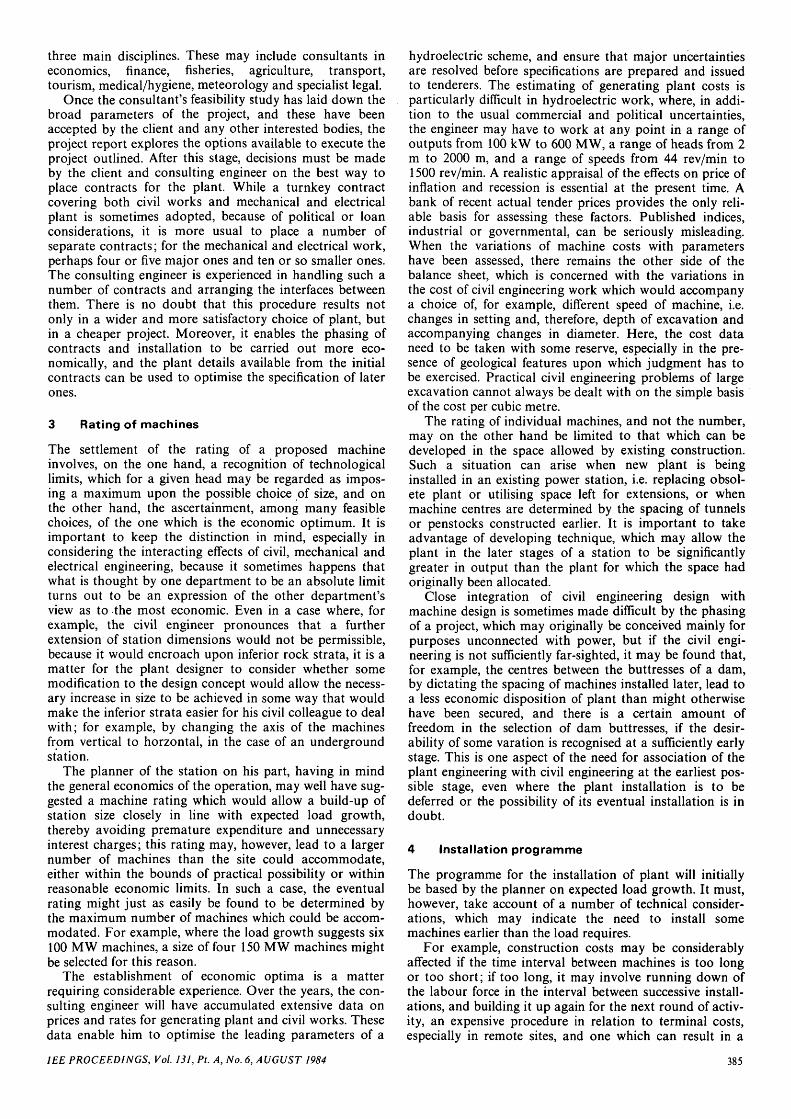
operation should be supervised jointly, and all branchesand tappings checked as pressure builds up. When filling iscomplete, all gates should be operated before plant com-missioning is allowed to proceed (Fig. 5).
Fig. 5 Foyers pumped storagePower station, Loch Ness and lower control works
Tests involving the hydrualic and transmission systemsshould also be organised jointly, so as to prove satisfactoryperformance with the minimum risk to personnel andplant and the minimum disturbance to electrically con-sumers. Instrumentation should be- provided to recordtransient conditions in the surge chamber, penstock, spiralcasing and draft tube, as well as the speed/frequency,power and voltage. Load assumption and rejection testsshould not be carried out until the machine under test hasbeen run light, and balanced at speeds up to thoseexpected to be reached on tripping. The machine may thenbe synchronised and loaded to, say, 25% of rated load.After the hydraulic conditions have settled it may then betripped. Recordings of speed and pressure variation and ofsurge chamber behaviour should then be inspected, andcompared with calculated values. If no serious discrep-ancies are found, further tests may be carried out, rejectingincreasing loads, until all operational conditions have beensimulated.
In pumped storage installations it is not possible tocarry out progressively larger pump-load rejection tests.The guide vanes of a reversible pump-turbine have lesscontrol of pump discharge than of turbine flow, while anormal pump has none. Thus pump tripping tests areusually carried out only at full discharge. Tests are some-times made from partial opening with pump-turbines, butthese may give more onerous pressure variations than full-discharge tripping. Such tests should, therefore, be carriedout only after the full-discharge tests have given resultswhich line up satisfactorily with design expectations, andare acceptable to the civil engineers as well as to the plantengineers.
388 IEE PROCEEDINGS, Vol. 131, Pt. A, No. 6, AUGUST 1984