Embed Size (px)
Citation preview
Role of decollement material with different rheological properties in the
structure of the Aljibe thrust imbricate (Flysch Trough, Gibraltar Arc):
an analogue modelling approach
Marıa Lujana,*, Fabrizio Stortib, Juan-Carlos Balanyaa, Ana Crespo-Blanca, Federico Rossettib
aDepartamento de Geodinamica, Instituto Andaluz de Ciencias de la Tierra, Universidad de Granada—CSIC, 18071 Granada, SpainbDipartimento di Scienze Geologiche, Universita “Roma Tre”, Largo S. L. Murialdo 1, 00146 Rome, Italy
Received 31 October 2001; received in revised form 24 June 2002; accepted 26 June 2002
Abstract
The Miocene Aljibe thrust imbricate (Flysch Trough), in the external zone of the Gibraltar Arc, shows large changes in structural style
towards the foreland. Rheological variation of the decollement rocks—Triassic evaporitic rocks and Mesozoic limestones—appears to be the
main factor controlling the contrasts in structural style that characterise adjacent wedge domains. In order to test this hypothesis, we carried
out analogue experiments involving three-dimensional variations of decollement material. A plate of viscous material was placed in the
central part of the models, at the base of the sand multilayers. Different geometries of the viscous plate were used. Experimental results show
a strong link between the rheological properties of the decollement material and the structure of the overlying thrust wedge. These results
compare well with the internal geometry and vergence distribution in the Aljibe thrust imbricate. Indeed, the tectonic style of the wedge can
be explained as a consequence of variations of rock type along the basal decollement.
q 2002 Elsevier Science Ltd. All rights reserved.
Keywords: Analogue modelling; Thrust imbricate; Decollement; Vergence distribution; Aljibe unit
1. Introduction
Variability in vergence and tectonic style both along and
across the structural trend of fold-and-thrust belts can be
related to the frictional or viscous behaviour of the main
decollement levels, as shown in the Jura mountains
(Laubscher, 1972), the Zagros (Colman-Saad, 1978), the
Spanish Pyrenees (Burbank et al., 1992), the Parry Islands
Foldbelt (Harrison and Bally, 1988), the Salt Range (Butler
et al., 1987), or the Mediterranean Ridge (Ryan et al., 1982).
Indeed, incompetent decollement rocks, like evaporites or
shales, enhance the delocalisation and outward propagation
of deformation (e.g. Geiser, 1988; Macedo and Marshak,
1999), and the growing fold-and-thrust belts attain extre-
mely narrow surface tapers (Davis and Engelder, 1985).
Thrust faults and folds within thrust wedges accreting above
low-friction basal decollements generally have no preferred
vergence (Davis and Engelder, 1985), and very complex
geometries can develop (e.g. Velaj et al., 1999).
The Aljibe thrust imbricate, which is the main tectonic
unit of the Flysch Complex, in the external zone of the
Gibraltar Arc (Betic–Rif orogenic belt), provides an
example of such structural complexity (Fig. 1). The pre-
contractional, three-dimensional (3D) geometry of decolle-
ment materials with different rheological properties appears
to be a key parameter controlling the structure and vergence
partitioning in the developing foreland belt. To gain insights
as to the role of this parameter, we performed sandbox
analogue experiments. The efficiency of analogue model-
ling for studying the influence of incompetent decollement
rocks under different boundary conditions on the evolution
of fold-and-thrust belts has been widely proven (Cobbold
et al., 1989, 1995; Dixon and Liu, 1992; Talbot, 1992;
Letouzey et al., 1995; Bonini et al., 2000; Cotton and Koyi,
2000, among others). Our experiments contribute to broaden
the available experimental templates for natural thrust
wedges. The fact that structural variations obtained in the
models compare with those observed in the study area
throws a new light on the 3D distribution of decollement
rocks at the base of the Aljibe thrust imbricate.
0191-8141/03/$ - see front matter q 2002 Elsevier Science Ltd. All rights reserved.
PII: S0 19 1 -8 14 1 (0 2) 00 0 87 -1
Journal of Structural Geology 25 (2003) 867–881
www.elsevier.com/locate/jstrugeo
* Corresponding author. Tel.: þ34-9-58-243158; fax: þ34-9-58-243384.
E-mail address: [email protected] (M. Lujan).

2. The Gibraltar Arc and the structure of the Aljibe Unit
The external zones within the Gibraltar Arc formed as an
arcuate fold-and-thrust belt due to the overall westward
emplacement of continental metamorphic rocks belonging
to the Alboran Domain (Betic–Rif hinterland) over the
external domain: the South Iberian and Maghrebian
paleomargins (inset of Fig. 1). The emplacement produced
the obliteration of the Flysch Trough during the Miocene
(Balanya and Garcıa-Duenas, 1988). This deep trough
developed on a transform zone of attenuated continental
lithosphere, eventually oceanic (Durand-Delga et al., 2000),
situated between the African and European plates and filled
by sediments from Cretaceous to Neogene times.
In the northern branch of the Gibraltar Arc (inset of Fig.
1), the units that belong to the Subbetic cover are derived
from the South Iberian paleomargin, composed of Triassic
to Cenozoic rocks. During the Early to Middle Miocene,
these rocks were detached from their Hercynian basement
and formed allochthonous units, shortened by WNW- to
NW-vergent folds and thrusts (e.g. Bourgois, 1978;
Crespo-Blanc and Campos, 2001, and references therein).
In the study area, the Subbetic sedimentary sequence
comprises: (a) a Triassic sequence of limestones and
dolomitised carbonate rocks (Muschelkalk facies), together
with gypsiferous claystones and fine-grained sandstones
(Keuper facies); (b) a Jurassic sequence of dolomite rocks
and overlying massive, predominantly shallow marine
Fig. 1. Structural map of the Aljibe unit. Cross-section illustrating the various style of deformation. Inset: main tectonic complexes in the Gibraltar Arc
(rectangle: study area).
M. Lujan et al. / Journal of Structural Geology 25 (2003) 867–881868
limestones; (c) an Early Cretaceous unconformity marked
by hard ground on top of the Jurassic limestones; and (d)
alternating pink pelagic marls and marly limestones, Late
Cretaceous to Paleogene in age (‘red beds’). In the western
sector of the study area, the Subbetic rocks consist
predominantly of Triassic evaporites, whose structural
position and emplacement age are largely controversial.
Flinch et al. (1996) proposed that these salt rocks were
emplaced originally within Mesozoic sedimentary sequence
in passive-margin setting. The diapiric allochthonous
masses were then overthrusted as an accretionary wedge
during the Miocene. By contrast, Bourgois (1978) claimed
that the Triassic rocks are polygenetic breccias, formed
during the Burdigalian, of Subbetic rocks in a gyspum
cement.
The Aljibe thrust imbricate is the main tectonic unit of
the Flysch Complex (Didon et al., 1973). The Paleogene
sequence of this unit comprises claystones and intercala-
tions of calcareous limestones, while the Neogene sequence
is composed of a characteristic quartzite formation with
minor marly levels, the Aljibe formation (Numidian of
northern Africa; Didon et al., 1973). This formation has
been dated as Aquitanian (Esteras et al., 1995). Structurally,
the Aljibe thrust imbricate (Fig. 1) consists of an in-
sequence leading imbricate fan (Boyer and Elliott, 1982)
formed between the Late Burdigalian and the Langhian due
to an approximately E–W shortening (Lujan et al., 1999).
This thrust wedge has been locally affected by a Serravallian
extensional episode, and moderate-angle normal faults
developed, as the fault which bounds the Aljibe and the
Penibetic units, in the northeastern part of Fig. 1 (Lujan
et al., 2000).
No penetrative structures have been found in the field,
and this indicates that rocks within the Aljibe thrust
imbricate underwent a negligible amount of internal strain.
In the eastern part of the study area (Fig. 1), tectonic
windows show that the imbricated stack detached above
Subbetic marly limestones (Late Cretaceous to Paleogene in
age). In the western and northwestern parts, the same kind of
exposures indicate that the sole thrust of the Aljibe thrust
imbricate (Aljibe sole thrust) detached above Triassic
evaporites. This variation of the substrate rocks below the
Aljibe sole thrust closely coincides with a major change in
structural style within the Aljibe thrust imbricate. In the
eastern domain, thrusts and folds systematically verge
towards the west, the width of the slices varying between 1
and 2 km, and their lateral continuity is frequently more
than 20 km. On the other hand, the western domain is
characterised by eastward-verging, irregularly spaced
thrusts, moderate lateral continuity of map structures and
extensive upright folding within the imbricate slices. The
boundary between the two domains trends approximately
N308E and roughly coincides with the alignment of tectonic
windows (Fig. 1). In the western domain, a second-order
narrow transpressional zone running N508E disrupts the
continuity of the thrust imbricates (southwestern part of the
map in Fig. 1).
3. Material properties and model kinematics
In the experiments, sand and silicone putty were used in a
natural gravity field to simulate the rheological behaviour of
sedimentary cover and salt rocks, respectively. Sand has long
been recognized as an appropriate analogue material for
simulating the Mohr–Coulomb behaviour of natural rock
multilayers undergoing brittle deformation at shallow crustal
levels (e.g. Davy and Cobbold, 1991). We used dry aolian
quartz sand with a grain size varying between 0.2 and
0.3 mm, a coefficient of internal friction f ¼ 37.58, and
density rb ¼ 1.5 g cm23, which exhibits a nearly perfect
Mohr–Coulomb behaviour (shear tests in Acocella et al.,
2000). Cohesion values are negligible up to 200 Pa under low
normal stress conditions (triaxial and shear tests; E. Marotta,
personal communication, 2002). Coloured sand was used to
provide horizontal passive markers within the undeformed
experimental multilayer. Silicone putty has been commonly
used as Newtonian material with a strain-rate-dependent
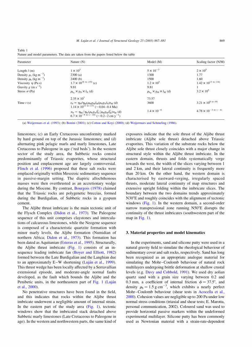
Table 1
Nature and model parameters. The data are taken from the papers listed below the table
Parameter Nature (N) Model (M) Scaling factor (N/M)
Length l (m) 1 £ 103 5 £ 1023 2 £ 105
Density rv (kg m23) 2300 (a) 1300 1.77
Density rb (kg m23) 2400 (b) 1500 1.60
Viscosity h (Pa s) 1.7 £ 1018 to (19) (c) 1.2 £ 105 1.42 £ 1013 to (14)
Gravity g (m s22) 9.81 9.81 1
Stress s (Pa) rbN£ gN £ lN (d) rbM
£ gM £ lM (d) 3.2 £ 105
2.35 £ 107 73.57
Time t (s) tN ¼ hN/hM(rMgMlM/rNgNlN)tM (d) 3600 3.21 £ 108 to (9)
1.14 £ 1012 to (13) (,0.04–0.4 Ma)
nN ¼ hM=hNðrNgNl2N=rMgMl2MÞnM (d) 1.4 £ 1026 4.78 £ 1023 to (24)
6.7 £ 1029 to (210) (,0.2–2 cm y21)
(a) Weijermars et al. (1993); (b) Bonini (2001); (c) Cotton and Koyi (2000); (d) Weijermars and Schmeling (1986).
M. Lujan et al. / Journal of Structural Geology 25 (2003) 867–881 869

viscosity for modelling the ductile flow of incompetent
decollement rocks like evaporites (e.g. Weijermars et al.,
1993; Cotton and Koyi, 2000; Bonini, 2001). The silicone
putty used in our experiments, manufactured by Rhodia (code
7007), had a density rv ¼ 1.3 g cm23 and a viscosity
h ¼ 1.2 £ 105 Pa s at a constant shortening rate of 0.5 cm/
h. For detailed rheology of this material and suitability as
model analogue, see Weijermars (1986).
Table 1 shows the characteristic values of the four
independent quantities—density (r ), length (l ), viscosity
(h ), and gravity (g )—for both natural prototype and
analogue materials. The table also shows the corresponding
scaling factors of the main physical parameters, according
to the approach of Weijermars and Schmeling (1986).
Scaling of the viscous decollement layer for an hour of
model time tM predicts a natural time tN of about 0.04 to
0.4 Ma, and a natural velocity vN ¼ 0.2 to 2 cm y21, for the
imposed model velocity vM ¼ 1.4 £ 1026 m s21 (Table 1).
These values are in good agreement with those of natural
thrust systems and those obtained previously in similar
analogue modelling experiments (e.g. Bonini, 2001).
The experiments were performed in a 100-cm-wide, 160-
cm-long sandbox with no side walls, schematically
illustrated in Fig. 2. A mylar sheet (coefficent of basal
friction mb ¼ 0.43) floored the sandbox. A 0.5-cm-thick
silicone plate with variable geometry was positioned above
the mylar sheet in the central part of the experimental
multilayers to simulate a basal evaporitic layer. An 80-cm-
long, 50-cm-wide, 1.5-cm-thick sandpack was sieved above
the mylar sheet and the central silicone plate, alternating
coloured and uncoloured layers. A reference grid of 4-cm-
sided squares was sieved onto the black top layer of the
sandpack. The mylar sheet was pulled at a constant rate of
0.5 cm h21 by an electric motor, causing collision of the
undeformed multilayer against the rigid, vertical backstop
provided by the end wall of the sandbox (Fig. 2). This forced
collision induced the growth of a Coulomb wedge in the
sandpack. The basal decollement of the sand wedge reached
the silicone plate after about 20 cm of shortening. Total
shortening was almost constant in all experiments, nearing
50% of the undeformed length of the sandpack. Different
shapes of the silicone plate were used in different
experiments. In particular, we varied the strike of the
boundary of the silicone plate facing the backstop with
respect to the strike of the backstop itself, which remained
fixed. In the 08 model, the silicone had a rectangular shape,
27 cm long and 22 cm wide; in the 15, 30 and 458 models
the angle between the strike of the silicone boundary and the
backstop was 15, 30 and 458, respectively (Fig. 2). The
changing geometry was recorded by time lapse photography
of the top surface. After completion, each model underwent
serial sectioning parallel to the shortening direction.
Duplication of the models allowed us to verify the
reproducibility of the experimental results.
The experimental setup in our simple models does not
account for plate flexure and isostatic compensation beneath
the growing wedges, for the role of pore fluid pressure, and
for the possibility of deformations affecting the backstop.
These limitations are very common in sandbox experiments
and have been shown not to significantly affect the first-
order model results at the proper distance from the backstop
(e.g. Malavieille, 1984; Liu et al., 1992; Koyi, 1995; Storti
and McClay, 1995; Gutscher et al., 1996; Storti and Salvini,
2000; Bonini, 2001). We made relative comparisons among
models constructed in the same experimental apparatus in
order to prevent any significant influence of model
limitations on our inferences.
4. Experimental results
In the early stages of shortening the whole wedge
underwent noteworthy detachment along the mylar–sand
boundary (rear frictional domain). With increased short-
ening, the basal decollement localised within the silicone
layer in the central region of the multilayer (viscous
domain) and remained located at the mylar–sand boundary
in the lateral sectors (lateral frictional domains; Fig. 2).
4.1. Frictional domains
The progressive evolution of thrust wedge growth above
the frictional domains was that of a typical Coulomb wedge
in which the basal friction was slightly lower than the
internal coefficient of friction of the wedge material (e.g.
Mulugeta, 1988; Liu et al., 1992; Storti and McClay, 1995).
Deformation was concentrated at the front of the wedge and
the traces of the thrust faults were almost rectilinear. In the
embryonic stage of wedge growth, i.e. when it was
developing above the rear frictional domain, the strike of
the backstop and the trace of the thrusts were parallel
Fig. 2. Simplified sketch of the experimental apparatus and model setting in
both cross-section and map view. The geometry of the basal silicone layer
in different experiments (0, 15, 30 and 458 models) is schematically
illustrated.
M. Lujan et al. / Journal of Structural Geology 25 (2003) 867–881870
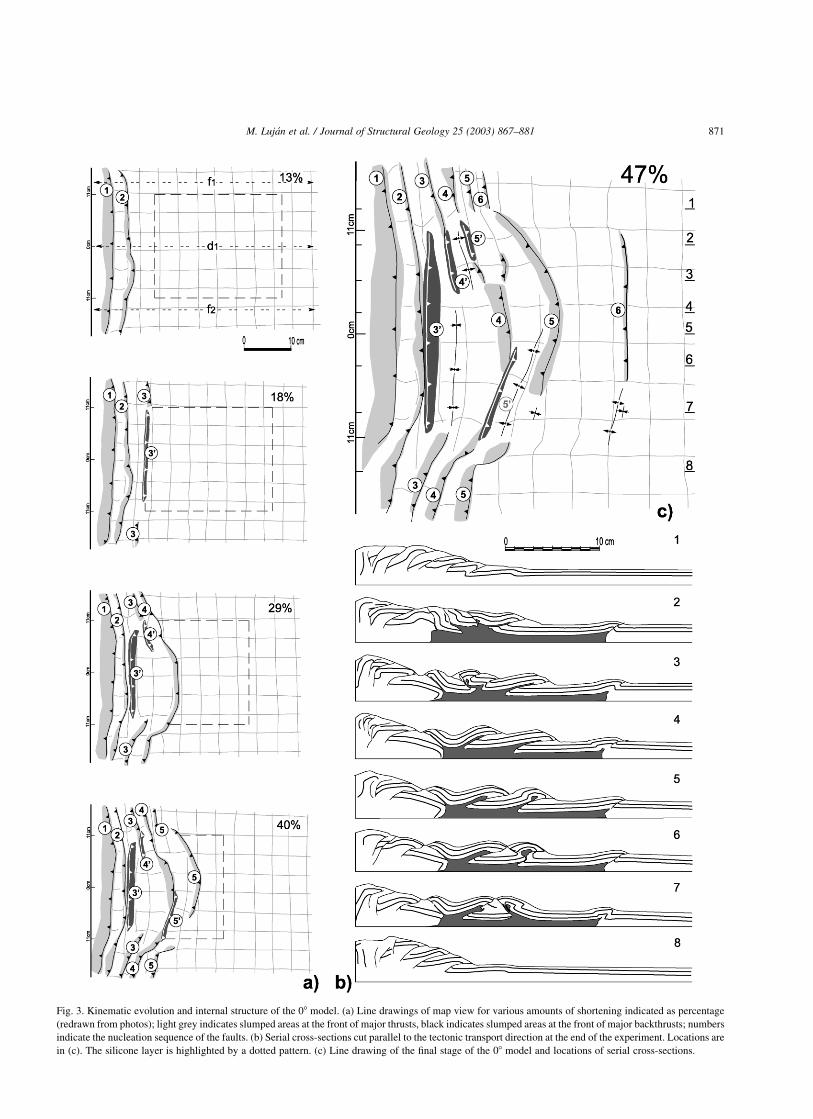
Fig. 3. Kinematic evolution and internal structure of the 08 model. (a) Line drawings of map view for various amounts of shortening indicated as percentage
(redrawn from photos); light grey indicates slumped areas at the front of major thrusts, black indicates slumped areas at the front of major backthrusts; numbers
indicate the nucleation sequence of the faults. (b) Serial cross-sections cut parallel to the tectonic transport direction at the end of the experiment. Locations are
in (c). The silicone layer is highlighted by a dotted pattern. (c) Line drawing of the final stage of the 08 model and locations of serial cross-sections.
M. Lujan et al. / Journal of Structural Geology 25 (2003) 867–881 871

M. Lujan et al. / Journal of Structural Geology 25 (2003) 867–881872

throughout the entire wedge (see the initial maps of
thrusting sequence in Figs. 3a–6a). Mature Coulomb
wedges developed in the lateral frictional domains, where
they consisted of imbricates of foreland-verging thrusts. The
imbricates were accreted in a piggyback fashion, producing
wedges with surface tapers varying between 15 and 258,
depending on the amount of underthrusting of the frontal
thrust sheet. The dip of the foreland-verging ramps
progressively increased from the toe to the rear of the
wedge, indicating passive backrotation of older thrust sheets
during the accretion of new material at the toe (e.g. Liu et al.,
1992; Mulugeta and Koyi, 1992). Backfolding and back-
thrusting were subordinate and mostly developed in the
conjugate limbs of the box anticlines at the wedge toe
during nucleation of new thrust sheets. Further development
of these fault-related folds systematically led to thrust
breakthrough and forelandward translation of the frontal
anticlines (e.g. Storti and Salvini, 1997). The final geometry
of thrust wedge sectors developed above the lateral
frictional domains is illustrated in the first and last cross-
sections of Figs. 3b–6b.
4.2. Viscous domain: general features
In all the experiments, where the sand wedge started
propagating above the viscous substrate, a drastic change
occurred in the deformation style. The forelandward
structural asymmetry of the wedge ceased and a major
backthrust generated, detached above the silicone. The
subsequent thrust development showed no preferred ver-
gence and included an approximately equal number of
foreland- and hinterland-verging thrusts (Figs. 3–6). A new
thrust wedge (external wedge) developed above the viscous
substrate, juxtaposed against the older wedge (internal
wedge) accreted above the rear frictional domain (Figs.
3b–6b). The surface taper of the external wedge decreased
to much lower values, between 5 and 08. This confirms the
direct proportionality between surface wedge taper and
basal friction (Davis and Engelder, 1985).
A striking difference involves the cross-sectional archi-
tecture of the two adjacent wedges (Fig. 7a): a simple
foreland-verging leading imbricate fan characterises the
internal wedge (e.g. Mulugeta, 1988; Liu et al., 1992; Koyi,
1995) whereas the external wedge shows a much more
complex internal geometry of fault and fold arrays. The
spacing between adjacent faults was much greater in the
viscous domain than in the frictional domains. Overprinting
and interference of former thrusts by younger backthrusts
occurred in the viscous domain of the models (see 4 and 50 in
Fig. 3c).
Wide and gentle synclinal sectors, bounded by opposite-
verging thrusts, are separated by narrow zones of intense
faulting and folding, globally defining pop-up and pop-
down structures (e.g. Letouzey et al., 1995; Cotton and
Koyi, 2000). Both foreland- and hinterland-verging anticli-
nes with large interlimb angles formed above layer-parallel
decollements within the silicone plate. Thrust ramps
frequently cut across the limbs of tighter anticlines, which
eventually underwent either forelandward or hinterland-
ward thrust breakthrough and translation. This suggests that
anticlines at the heads of thrust sheets formed by the
temporal transition from decollement folding, to fault-
propagation folding, up to fault-bend folding (Dixon and
Liu, 1992; Storti and Salvini, 1997).
The asymmetrical load, produced by the weight of the
internal wedge on the first thrust sheet of the external
wedge, detached above the viscous layer, caused the
outward squeezing of silicone, as indicated by the
systematic downward-facing attitude of layering contiguous
to the silicone (Figs. 3b–6b). The outward flow of the
internal portion of the silicone plate caused it to almost
double in thickness in the more external areas. The vertical
flow of the ductile layer was enhanced by the pop-up
structures, where ductile material was squeezed within the
core of the anticlines, in places producing diapir-like
structures (Fig. 7b). On the other hand, pop-down structures
progressively sank into the viscous basal plate, acting as
partial barriers to the forward migration of the silicone, as
observed in cross-section 5 of the 158 model (Fig. 4b) (e.g.
Cotton and Koyi, 2000). It is worth noting that density
contrast in nature is lower than that of the analogue material
(rbN=rvN
¼ 1:04 vs rbM=rvM
¼ 1:15, respectively, see Table
1). Consequently, buoyancy-driven processes are enhanced
in the models.
The occurrence of a basal layer of viscous material
facilitated the outward propagation of the deformation front
in the central region of the experiments with respect to the
lateral frictional domains. This modified the trace of the
deformation front, from a rectilinear shape in the early
stages of shortening, because to an outwardly convex shape
with increased shortening. Consequently, structures notice-
ably non-cylindrical, as indicated by the abrupt changes in
adjacent cross-sections of Figs. 3b–6b. Foreland-verging
domains alternate along the strike with hinterland verging
and rather symmetrical domains. A well developed salient
(e.g. Macedo and Marshak, 1999) characterised the final
stage of all experiments (Figs. 3c–6c).
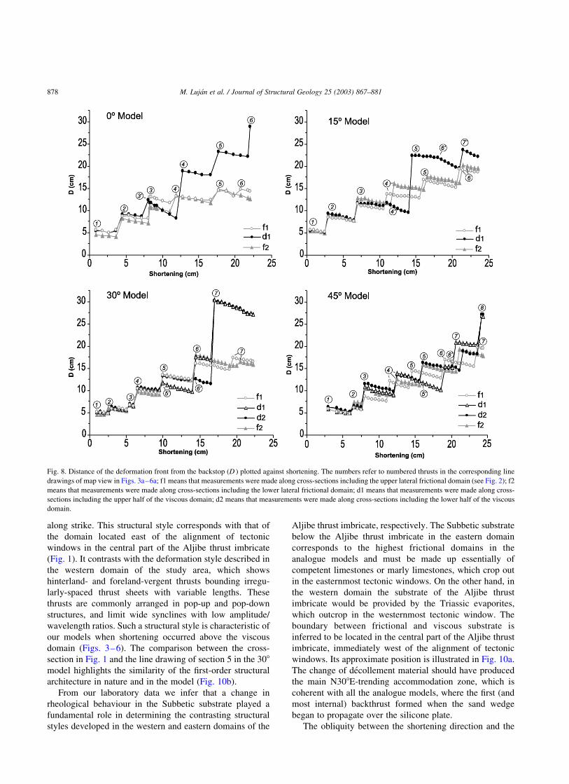
Systematic monitoring of the distance of the deformation
front from the backstop (D; Fig. 8) shows a typical saw-
tooth shape, indicating that the thrust wedge growth
occurred by discrete and abrupt widening pulses, separated
by longer narrowing periods (Storti and Salvini, 2000). In all
Fig. 4. Kinematic evolution and internal architecture of the 158 model. (a) Line drawings of map view at different amounts of shortening. (b) Serial cross-
sections cut parallel to the tectonic transport direction at the end of the experiment. Locations are in (c). (c) Line drawing of the final stage of the 158 model and
locations of serial cross-sections.
M. Lujan et al. / Journal of Structural Geology 25 (2003) 867–881 873

M. Lujan et al. / Journal of Structural Geology 25 (2003) 867–881874

experimental configurations, the early evolutionary stages
show very similar behaviours, in both the viscous and
frictional domains (Fig. 8). In the viscous domain, the
deformation rate along backthrusts was higher than along
foreland thrusts, as shown by the increase in negative slope
marked by segments that correspond to backthrusts (for
example, segment 30 of plot 08 model; Fig. 8). An abrupt
increase of D values occurred in the viscous domain,
whereas in the lateral regions of frictional substrate, D
maintained its progression.
4.3. Viscous substrate: influence of geometry
The general features that are common to all experiments
are complicated by specific geometric and kinematic
patterns dictated by the shape of the viscous material.
Differences are best expressed in map view. In the 08 model,
the rear boundary between the frictional and viscous
substrates was parallel to the backstop, i.e. perpendicular
to the shortening direction (Fig. 2). When the wedge
propagated above the basal viscous layer (18% of short-
ening), the first major backthrust formed parallel to the
sand–silicone boundary. The younger major thrust (2 in Fig.
3a) and the newly-formed backthrust (30) had the same
strike. Two thrust segments formed in the lateral frictional
domains (3), almost colinear to backthrust 30. As a result of
increasing shortening (29%) a wide frontal piggy-basin
formed. The difference in deformation styles between
viscous and frictional domains and the foreward jump of
the deformation front across the basal silicone plate were
accommodated by transfer zones striking parallel to the
shortening direction (e.g. Cotton and Koyi, 2000). After
29% of shortening, the contractional structures showed an
increasing curvature of their map traces as deformation
progressed (Fig. 3a). This curvature was accommodated by
thrusts and/or backthrust imbricates in the transfer zones
parallel to the shortening direction, which was a feature
common to all models.
In the 08 model, where the lateral viscous–frictional
boundaries had the same length and were both parallel to the
shortening direction, the final geometry was broadly
symmetrical. Some of the passive markers situated within
the transfer zone and originally parallel to the shortening
direction showed rotations towards the lateral frictional
domains, outwards to the arcuate thrust, like those located at
the rear of thrust 5 (Fig. 3c). This implies that extension
must have occurred along the trend of this particular thrust,
as the length of the markers initially parallel to the backstop
increased. Nevertheless, the small amount of extension,
estimated at 6% by measuring the initial and final length of
the markers, did not produce noticeable extensional
structures.
In the 158 model, the rear boundary between the viscous
and the frictional domains formed an angle of 158 to the
backstop (Fig. 2). When the imbricate thrust fan began to
propagate over the silicone substrate (27% of shortening), a
backthrust formed parallel to the sand–silicone boundary,
decapitating the pre-existing thrust-related anticline. An
oblique accommodation zone was produced (Fig. 4a). The
shape of the new frontal thrust was strongly influenced by
the variable rheology at the bottom of the multilayer and a
strongly arcuate thrust formed above the viscous domain
(37% of shortening). An abrupt forelandward jump of the
deformation front produced a wide piggyback basin in
which out-of-sequence shortening occurred (Fig. 4a and c).
The leading anticline bounding the piggyback basin
forelandward was then decapitated by a newly-formed
backthrust localised above the viscous domain (41% of
shortening). In this model, more backthrusts than thrusts
were produced above the viscous domain. Their strike was
slightly oblique to the backstop and the resulting geometry
was slightly asymmetric.
The 308 model was characterised by an angle of 308
between the frictional–viscous rear boundary and the
backstop (Fig. 2), which resulted in strongly asymmetric
3D-structures. When the deformation front approached the
viscous material (24% of shortening), a major backthrust
formed near the upper corner of the silicone layer, parallel to
the frictional–viscous rear boundary, and an oblique
accommodation zone formed (Fig. 5a). At the same time,
deformation in the central and lower sectors continued
above a frictional decollement and a major thrust originated,
striking parallel to the backstop. With increasing shortening,
the deformation front was strongly segmented (33% of
shortening). A major foreland-verging thrust segment
propagated from the rear frictional domain into the upper
half of the viscous domain, striking parallel to the backstop.
Close to its termination, displacement was transferred to an
outward-concave backthrust arranged in ‘en echelon’
fashion with the thrust. The major segment of the backthrust
was almost parallel to the viscous–frictional boundary (Fig.
5a). A major outward jump of the deformation front
occurred in the viscous domain at about 39% of shortening,
while thrust spacing in the lateral frictional domains
remained almost constant. A wide piggyback basin formed
above the viscous domain and underwent out-of-sequence
thrusting and folding with increased shortening (Figs. 5a
and c and 9).
In the 458 model, the total volume of the silicone
basal plate was reduced approximately to half that of the
08 model and the rear boundary between the frictional
Fig. 5. Kinematic evolution and internal structure of the 308 model. (a) Line drawings of map view at different amounts of shortening (redrawn from photos).
(b) Serial cross-sections cut parallel to the tectonic transport direction at the end of the experiment. Locations are in (c). (c) Line drawing of the final stage of the
308 model and locations of serial cross-sections.
M. Lujan et al. / Journal of Structural Geology 25 (2003) 867–881 875

M. Lujan et al. / Journal of Structural Geology 25 (2003) 867–881876

and viscous domains formed an angle of 458 to the
backstop (Fig. 2). The tendency to thrust segmentation
highlighted in the 308 model was enhanced in this
experiment due to the strong lateral variations of the area
floored with viscous material. Consequently, the resulting
geometry is the most asymmetric of all the models
presented. The structural architecture of 458 model was
governed by thrusts striking almost parallel to the
backstop even when they propagated into the viscous
domain. At 27% shortening, when the thrust wedge
reached the sharp corner of the viscous domain, a small
inflection of the frontal foreland thrust occurred. With
increasing shortening, two short backthrusts originated in
the viscous domain, interfering with a major thrust. Their
overall strike was sub-parallel to the backstop (Fig. 6a).
Only close to the end of the experiment did the
deformation front reach the outer boundary of the
silicone plate, producing a piggyback basin (52% of
shortening). The envelope of the backthrust terminations,
including second-order structures accommodating displa-
cement transfer between thrusts and backthrusts, bounds
a complex deformation zone, which strikes almost
parallel to the frictional-viscous rear boundary (Fig. 6b
and c).
To summarise, an increase of the angle between the
frictional–viscous rear boundary and the backstop causes
the following major effects: (1) a major asymmetry of the
resulting 3D structure; (2) the length of the first-order
backthrusts decreases; (3) the degree of fault segmentation
increases; (4) the geometric correlation between the strike
of the frictional–viscous rear boundary and that of the
overlying faults decreases; and (5) the amount of shortening
required for a development of the frontal piggyback basin
increases.
5. Implications for the 3D structure of the Aljibe thrust
imbricate
Striking features of the models described in this paper,
which can be compared with structural features described in
the Aljibe Unit, are: (1) the different style of deformation
recognized between areas of the experimental wedge
accreted above frictional (sand) or viscous (silicone)
substrate; and (2) the final geometry of the shortened
models, which can be directly correlated with the initial
geometry of the viscous domain, as the asymmetric shapes
of the viscous domain create accommodation zones oblique
to the shortening direction.
Experimental wedge sectors that resulted from short-
ening above frictional domains are characterised by fore-
land-vergent thrusts and fault-related folds striking
subperpendicular to the shortening direction (e.g. Liu et al.,
1992). Thrust sheets are regularly spaced and continuous
Fig. 6. Kinematic evolution and internal structure of the 458 model. (a) Line drawings of map view at different amounts of shortening (redrawn from photos).
(b) Serial cross-sections cut parallel to the tectonic transport direction at the end of the experiment. Locations are in (c). (c) Line drawing of the final stage of the
458 model and locations of serial cross-sections.
Fig. 7. Photographs representative of final cross-sections of the experimental wedges. (a) Section 3 of the 308 model (see Fig. 5), showing the striking difference
of style occurring between the internal and external wedges above frictional and viscous substrate, respectively. (b) Section 6 of the 08 model (see Fig. 3),
showing silicone putty squeezed in the core of an anticline of the external wedge.
M. Lujan et al. / Journal of Structural Geology 25 (2003) 867–881 877
along strike. This structural style corresponds with that of
the domain located east of the alignment of tectonic
windows in the central part of the Aljibe thrust imbricate
(Fig. 1). It contrasts with the deformation style described in
the western domain of the study area, which shows
hinterland- and foreland-vergent thrusts bounding irregu-
larly-spaced thrust sheets with variable lengths. These
thrusts are commonly arranged in pop-up and pop-down
structures, and limit wide synclines with low amplitude/
wavelength ratios. Such a structural style is characteristic of
our models when shortening occurred above the viscous
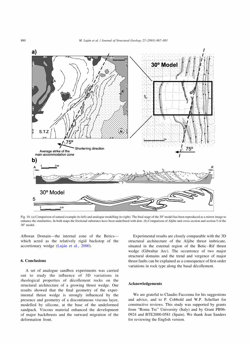
domain (Figs. 3–6). The comparison between the cross-
section in Fig. 1 and the line drawing of section 5 in the 308
model highlights the similarity of the first-order structural
architecture in nature and in the model (Fig. 10b).
From our laboratory data we infer that a change in
rheological behaviour in the Subbetic substrate played a
fundamental role in determining the contrasting structural
styles developed in the western and eastern domains of the
Aljibe thrust imbricate, respectively. The Subbetic substrate
below the Aljibe thrust imbricate in the eastern domain
corresponds to the highest frictional domains in the
analogue models and must be made up essentially of
competent limestones or marly limestones, which crop out
in the easternmost tectonic windows. On the other hand, in
the western domain the substrate of the Aljibe thrust
imbricate would be provided by the Triassic evaporites,
which outcrop in the westernmost tectonic window. The
boundary between frictional and viscous substrate is
inferred to be located in the central part of the Aljibe thrust
imbricate, immediately west of the alignment of tectonic
windows. Its approximate position is illustrated in Fig. 10a.
The change of decollement material should have produced
the main N308E-trending accommodation zone, which is
coherent with all the analogue models, where the first (and
most internal) backthrust formed when the sand wedge
began to propagate over the silicone plate.
The obliquity between the shortening direction and the
Fig. 8. Distance of the deformation front from the backstop (D ) plotted against shortening. The numbers refer to numbered thrusts in the corresponding line
drawings of map view in Figs. 3a–6a; f1 means that measurements were made along cross-sections including the upper lateral frictional domain (see Fig. 2); f2
means that measurements were made along cross-sections including the lower lateral frictional domain; d1 means that measurements were made along cross-
sections including the upper half of the viscous domain; d2 means that measurements were made along cross-sections including the lower half of the viscous
domain.
M. Lujan et al. / Journal of Structural Geology 25 (2003) 867–881878

frontal accommodation zone modelled in the asymmetric
models (15, 30 and 458 models) suggests that in the natural
example, the boundary between the frictional and ductile
substrate is oblique with respect to the shortening direction.
Kinematic indicators show a foreland transport direction in the
Aljibe thrust imbricate towards the WNW (Fig. 1). This
direction is at a high angle (about 758) to the main N308E-
trending accommodation zone. Moreover, the striking simi-
larity between 308model and the natural example, both in map
view and in cross-section (Fig. 10), suggests that the boundary
between the limestones and the Triassic evaporites initially
formed an angle of approximately 308 to the shortening
direction.
In the previous sections, it has been shown that the
western domain of the Aljibe thrust imbricate is divided into
two parts by a transpressive zone, which runs approximately
NE–SW (labelled S.T.Z. in Fig. 10). The origin of this
second-order feature might be included in the variability
range of structural trends developed above the viscous
domain in asymmetric models. An alternative possibility to
explain this N508E-trending transpressional zone is to relate
it to a change in the viscosity of the decollement material,
due to a lithological variation. Indeed, the southernmost
tectonic windows of Subbetic material show that upper
Cretaceous to Paleogene rocks (red beds) form the substrate
of the Aljibe thrust imbricate. The red beds are locally very
rich in clay materials, which may have enhanced their
viscous behaviour (Weijermars et al., 1993). Accordingly, it
is suggested that this second-order accommodation zone
within the viscous domain may be related to variations of
viscosity at the footwall of the Aljibe unit sole thrust. These
rheological variations are due to a change in lithology from
evaporites to red beds.
The inference that the basal decollement of the
Aljibe thrust imbricate is located in the evaporitic rocks
towards the west raises a basic geometric and kinematic
problem because it apparently implies a deepening of
the sole thrust towards the foreland (from Paleogene to
the east, to Triassic rocks to the west). This apparent
problem can be overcome by relaxing the assumption of
an undeformed foreland before contraction took place in
the area. According to Flinch et al. (1996), a first
diapiric emplacement of Triassic evaporitic rocks
occurred during the Mesozoic–Cenozoic passive margin
evolution of the South Iberian Domain. This diapiric
event may have imparted the proper lithological
heterogeneity to the South Iberian Domain for explain-
ing the 3D variations of rock types constituting the
substrate of the Aljibe thrust imbricate during its
tectonic emplacement in a contractional environment.
Shortening was probably driven by a push-from-behind
mechanism, due to the westward migration of the
Fig. 9. Photograph showing an oblique view of the final stage of the 308 model.
M. Lujan et al. / Journal of Structural Geology 25 (2003) 867–881 879
Alboran Domain—the internal zone of the Betics—
which acted as the relatively rigid backstop of the
accretionary wedge (Lujan et al., 2000).
6. Conclusions
A set of analogue sandbox experiments was carried
out to study the influence of 3D variations in
rheological properties of decollement rocks on the
structural architecture of a growing thrust wedge. Our
results showed that the final geometry of the exper-
imental thrust wedge is strongly influenced by the
presence and geometry of a discontinuous viscous layer,
modelled by silicone, at the base of the undeformed
sandpack. Viscous material enhanced the development
of major backthrusts and the outward migration of the
deformation front.
Experimental results are closely comparable with the 3D
structural architecture of the Aljibe thrust imbricate,
situated in the external region of the Betic–Rif thrust
wedge (Gibraltar Arc). The occurrence of two major
structural domains and the trend and vergence of major
thrust faults can be explained as a consequence of first-order
variations in rock type along the basal decollement.
Acknowledgements
We are grateful to Claudio Faccenna for his suggestions
and advice, and to P. Cobbold and W.P. Schellart for
constructive reviews. This study was supported by grants
from “Roma Tre” University (Italy) and by Grant PB96-
0924 and BTE2000-0581 (Spain). We thank Jean Sanders
for reviewing the English version.
Fig. 10. (a) Comparison of natural example (to left) and analogue modelling (to right). The final stage of the 308 model has been reproduced as a mirror image to
enhance the similarities. In both maps the frictional substrates have been underlined with dots. (b) Comparison of Aljibe unit cross-section and section 5 of the
308 model.
M. Lujan et al. / Journal of Structural Geology 25 (2003) 867–881880

References
Acocella, V., Faccenna, C., Funiciello, R., Rossetti, F., 2000. Sand-box
modeling of basement-controlled transfer zones in extensional domains.
Terra Nova 11/4, 149–156.
Balanya, J.C., Garcıa-Duenas, V., 1988. El cabalgamiento cortical de
Gibraltar y la tectonica de Beticas y Rif. In: Sociedad Geologica de
Espana. Actas, Segundo Congreso Geologico de Espana (Simposios),
Granada, pp. 35–44.
Bonini, M., 2001. Passive roof thrusting and forelandward fold propagation
in scaled brittle–ductile physical models of thrust wedges. Journal of
Geophysical Research (B2) 106, 2291–2311.
Bonini, M., Sokoutis, D., Mulugeta, G., Katrivanos, E., 2000. Modeling
hanging wall accommodation above rigid thrust ramps. Journal of
Structural Geology 22/8, 1165–1179.
Bourgois, J. (Ed.), 1978. La transversale de Ronda (Cordilleres Betiques,
Espagne). Donnees geologiques pour un modele d’evolution de l’Arc de
Gibraltar. Annales Scientifiques de l’Universite de Besancon (France) 30.
Boyer, S., Elliott, D., 1982. Thrust systems. The American Association of
Petroleum Geologists Bulletin 66/9, 1196–1230.
Burbank, D.W., Verges, J., Munoz, J.A., Bentham, P., 1992. coeval
hindward-imbricating and forward-imbricating thrusting in the South-
Central Pyrenees, Spain—timing and rates of shortening and depo-
sition. Geological Society of America Bulletin 104/1, 3–17.
Butler, R.W.H., Coward, H.P., Harwood, G.M., Knipe, R., 1987. Salt. Its
control on thrust geometry, structural style and gravitational collapse
along the Himalaya mountain front in the Salt Range of northern
Pakistan. In: O’Brien, J.-J., Lerche, I. (Eds.), Dynamical Geology of
Salt and Related Structures, Academic Press, London, pp. 399–418.
Cobbold, P.R., Rossello, E., Vendeville, B., 1989. Some experiments on
interacting sedimentation and deformation above salt horizons. Bulletin
de la Societe Geologique de France 8/3, 453–460.
Cobbold, P.R., Szatmari, P., Demercian, L.S., Coelho, D., Rossello, E.A.,
1995. Seismic and experimental evidence for thin-skinned horizontal
shortening by convergent radial gliding on evaporates, deep-water
Santos Basin, Brazil. In: Jackson, M.P.A., Roberts, D.G., Snelson, S.
(Eds.), Salt Tectonics: A Global Perspective. American Association of
Petroleum Geologists, Memoir 65, pp. 305–321.
Colman-Saad, S.P., 1978. Fold development in Zagros simply folded belt,
southwest Iran. American Association of Petroleum Geologists Bulletin
62, 984–1003.
Cotton, J., Koyi, H., 2000. Modeling of thrust front above ductile and
frictional detachments: application to structures in the Salt Range and
Potwar Plateau, Pakistan. Geological Society of America Bulletin 112/
3, 351–363.
Crespo-Blanc, A., Campos, J., 2001. Structure and kinematics of the South
Iberian paleomargin and its relationship with the Flysch Trough units:
extensional tectonics within the Gibraltar Arc fold-and-thrust belt
(western Betics). Journal of Structural Geology 23/10, 1615–1630.
Davis, D.M., Engelder, T., 1985. The role of salt in fold-and-thrust belts.
Tectonophysics 119, 67–88.
Davy, P., Cobbold, P.R., 1991. Experiments on shortening of a 4-layer
model of the continental lithosphere. Tectonophysics 188, 1–25.
Didon, J., Durand-Delga, M., Kornporbst, J., 1973. Homologies geologi-
ques entre les deux rives du Detroit de Gibraltar. Bulletin de la Societe
geologique de France 7/15, 77–105.
Dixon, J.M., Liu, S., 1992. Centrifuge modelling of the propagation of
thrust faults. In: McClay, K.R., (Ed.), Thrust Tectonics, Chapman and
Hall, London, pp. 53–69.
Durand-Delga, M., Rossi, P., Olivier, P., Puglisi, D., 2000. Situation
structurale et nature ophiolitique de roches basiques jurassiques
associees aux flyschs maghrebins du Rif (Maroc) et de Sicile (Italie).
Comptes-Rendus de l’Academie des Sciences de Paris, Earth and
Planetary Sciences 331, 29–38.
Esteras, M., Feinberg, H., Durand-Delga, M., 1995. Nouveaux elements sur
l’age des gres numidiensde la nappe de l’Aljibe (Sud-Ouest de
l’Andalousie, Espagne). Abstracts of Proceedings, IV Coloquio Inter-
nacional sobre el enlace Fijo del Estrecho de Gibraltar, Sevilla, SECEG.
Flinch, J., Bally, A., Wu, S., 1996. Emplacement of a passive-margin
evaporitic allochthon in the Betic Cordillera of Spain. Geology 14/1,
67–70.
Geiser, P.A., 1988. Mechanisms of thrust propagation: some examples and
implications for the analysis of overthrust terranes. Journal of Structural
Geology 10, 829–845.
Gutscher, M.A., Kukowski, N., Malavieille, J., Lallemand, S., 1996.
Cyclical behavior of thrust wedges—insights from high basal friction
sandbox experiments. Geology 24/2, 135–138.
Harrison, J.C., Bally, A.W., 1988. Cross-sections of the Parry Island
foldbelt on Melville Island. Canadian Petroleum Geologist Bulletin 81,
398–423.
Koyi, H., 1995. Mode of internal deformation in sand wedges. Journal of
Structural Geology 17/2, 293–300.
Laubscher, H.P., 1972. Some overall aspects of the Jura dynamics.
American Journal of Science 272, 293–304.
Letouzey, J., Colletta, B., Vially, R., Chermette, J.C., 1995. Evolution of
salt-related structures in compressional settings. In: Jackson, M.P.A.,
Roberts, D.G., Snelson, S. (Eds.), Salt Tectonics: A Global Perspective:
American Association of Petroleum Geologists Memoir 65, pp. 41–60.
Liu, H., McClay, K.R., Powell, D., 1992. Physical models of thrust wedges.
In: McClay, K.R., (Ed.), Thrust Tectonics, Chapman and Hall, London,
pp. 71–81.
Lujan, M., Crespo-Blanc, A., Balanya, J.C., 1999. Structure and kinematics
of the Aljibe Unit, north of Cadiz Province (Flysch Trough Complex,
Betics). Geogaceta 26, 47–50.
Lujan, M., Balanya, J.C., Crespo-Blanc, A., 2000. Contractional and
extensional tectonics in Flysch and Penibetic units (Gibraltar Arc, SW
Spain): new constraints on emplacement mechanisms. Comptes-Rendus
de l’Academie des Sciences de Paris, Earth and Planetary Sciences 330,
631–638.
Macedo, J., Marshak, S., 1999. Control on the geometry of fold–thrust belt
salients. Geological Society of America Bulletin 111/12, 1808–1822.
Malavieille, J., 1984. Modelisation experimentale des chevauchements
imbriques: Application aux chaınes de montagnes. Bulletin de la
Societe Geologique de France 26, 129–138.
Mulugeta, G., 1988. Modelling the geometry of Coulomb Thrust wedges.
Journal of Structural Geology 10, 847–859.
Mulugeta, G., Koyi, H., 1992. Episodic accretion and strain partitioning in a
model sand wedge. Tectonophysics 202, 319–333.
Ryan, W.B.F., Kastens, K.A., Cita, B.M., 1982. Geological evidence
concerning compressional tectonics in the Eastern Mediterranean.
Tectonophysics 86, 213–242.
Storti, F., McClay, K., 1995. Influence of syntectonic sedimentation on
thrust wedges in analogue models. Geology 23, 999–1002.
Storti, F., Salvini, F., 1997. Fault-related folding in sandbox analogue
models of thrust wedges. Journal of Structural Geology 19/3– 4,
583–602.
Storti, F., Salvini, F., 2000. Synchronous and velocity-partitioned thrusting
and thrust polarity reversal in experimentally produced, doubly-vergent
thrust wedges: implications for natural orogens. Tectonics 19/2, 378–396.
Talbot, C.J., 1992. Centrifuged models of Gulf of Mexico profiles. Marine
and Petroleum Geology 2, 412–432.
Velaj, T., Davison, I., Serjani, A., Alsop, I., 1999. Thrust tectonics and the
role of evaporites in the Ionian Zone of the Albanides. American
Association of Petroleum Geologists Bulletin 83, 1408–1425.
Weijermars, R., 1986. Flow behavior and physical chemistry of bouncing
putties and related polymers in view of tectonic laboratory applications.
Tectonophysics 217, 143–174.
Weijermars, R., Schmeling, H., 1986. Scaling of Newtonian and non-
Newtonian fluid dynamics without inertia for quantitative modelling of
rock flow due to gravity (including the concept of rheological
similarity). Physics of the Earth Planetary Interior 43, 316–330.
Weijermars, R., Jackson, M.P.A., Vendiville, B., 1993. Rheological and
tectonic modeling of salt provinces. Tectonophysics 217, 143–174.
M. Lujan et al. / Journal of Structural Geology 25 (2003) 867–881 881


![The Rheological Behavior of Kaolin Suspensions - ThaiScience · 272 Chiang Mai J. Sci. 2006; 33(3) rheological behavior of suspensions [6-9]. The rheological behavior of kaolin suspensions](https://img.pdfslide.us/doc/110x75/5d63e43b88c993c1628b47e2/the-rheological-behavior-of-kaolin-suspensions-272-chiang-mai-j-sci-2006.jpg)