Embed Size (px)
Citation preview
ROLE OF CURRENT DENSITY IN IMPRESS CURRENT
CATHODIC PROTECTION OF STAINLESS STEEL
IN 3.5% NaCl SOLUTION
JUSTIN GERARD A/L K.GERARD
FACULTY OF ENGINEERING
UNIVERSITY OF MALAYA
KUALA LUMPUR
2015
ROLE OF CURRENT DENSITY IN IMPRESS CURRENT
CATHODIC PROTECTION OF STAINLESS STEEL
IN 3.5% NaCl SOLUTION
JUSTIN GERARD A/L K.GERARD
RESEARCH REPORT SUBMITTED IN PARTIAL
FULFILLMENT OF THE REQUIREMENT FOR THE
DEGREE OF MASTER OF ENGINEERING
FACULTY OF ENGINEERING
UNIVERSITY OF MALAYA
KUALA LUMPUR
2015
ii
UNIVERSITY OF MALAYA
ORIGINAL LITERARY WORK DECLARATION
Name of Candidate: Justin Gerard A/L K.Gerard (I.C/Passport No:
Registration/Matric No: KMB 130010
Name of Degree: Masters of Engineering (Materials Engineering and Technology)
Title of Project Paper/Research Report/Dissertation/Thesis (“this Work”):
Masters of Engineering (Materials Engineering and Technology)
Field of Study: Corrosion
I do solemnly and sincerely declare that:
(1) I am the sole author/writer of this Work;
(2) This Work is original;
(3) Any use of any work in which copyright exists was done by way of fair
dealing and for permitted purposes and any excerpt or extract from, or reference
to or reproduction of any copyright work has been disclosed expressly and
sufficiently and the title of the Work and its authorship have been acknowledged
in this Work;
(4) I do not have any actual knowledge nor do I ought reasonably to know that
the making of this work constitutes an infringement of any copyright work;
(5) I hereby assign all and every rights in the copyright to this Work to the
University of Malaya (“UM”), who henceforth shall be owner of the copyright in
this Work and that any reproduction or use in any form or by any means
whatsoever is prohibited without the written consent of UM having been first had
and obtained;
(6) I am fully aware that if in the course of making this Work I have infringed
any copyright whether intentionally or otherwise, I may be subject to legal action
or any other action as may be determined by UM.
Candidate’s Signature Date:
Subscribed and solemnly declared before,
Witness’s Signature Date:
Name:
Designation:
iii
ABSTRACT
Impress current cathodic protections are common method of protecting steel structure from
corrosion attack. The structure are supplied with cathodic current that reduced the corrosion
rate. However if the magnitude of current supplied are insufficient, the structure will not be
able to be protected and if the current supplied it too high, hydrogen embrittelement may
occur. This research studies the effect of cathodic current density on stainless steel by
electrochemical testing. A potentiodynamic polarisation test was conducted with stainless
steel 316L and 304 in a 3.5% NaCl electrolytic solution. Stainless steel is resistance to
corrosion in most atmospheric environment, nonetheless stainless steel is susceptible to
pitting corrosion. The effect and the behaviour of stainless steel 316L and 304 under
cathodic current are observed in this research as well. The metal surface was analysed by
Scanning Electron Microscope and Energy Dispersive X-Ray. The test result indicate that
pitting corrosion occur more in 304 stainless steel. On the other hand 316L stainless steel,
show a more pitting resistance and slow cathodic rate.
iv
ABSTRAK
Perlindungan katod arus bekasan adalah kaedah yang sering digunakan untuk melindungi
struktur keluli daripada karatan. Struktur yang dibekalkan dengan arus katodik akan
mengurangkan kadar kakisan. Walau bagaimanapun, sekiranya magnitud arus yang
dibekalkan tidak mencukupi, struktur tersebut tidak akan dapat dilindungi. Sekiranya arus
yang dibekalkan adalah terlalu tinggi, kerapuhan hidrogen mungkin terjadi. Penyelidikan
ini mengkaji kesan ketumpatan arus katodik pada keluli tahan karat menggunakan
pengujian elektrokimia. Satu ujian pengutuban potensiodinamik dijalankan dengan keluli
tahan karat 316L dan 304 dalam larutan elektrolitik 3.5%NaCl. Keluli tahan karat
mempunyai rintangan terhadap kakisan dalam kebanyakan persekitaran atmosferik, tetapi
masih terdedah pada kakisan lubang/bopeng. Kesan dan kelakuan keluli tahan karat 316L
dan 304 yang dikenakan arus katodik juga diperhatikan dalam penyelidikan ini. Permukaan
logam dianalisis menggunakan Mikroskop Imbasan Elektron dan Serakan Tenaga Sinar-X.
Keputusan ujian menunjukkan bahawa kakisan lubang berlaku lebih banyak pada keluli
tahan karat 304. Manakala keluli tahan karat 316L menunjukkan lebih rintangan terhadap
kakisan lubang dan kadar katodik yang perlahan.

v
ACKNOWLEDGEMENTS
I would like to take this opportunity to convey my earnest and heartfelt gratitude
and recognition to each and every one who has supported, motivated, reinforced and
assisted me in completing this research project.
Firstly, I would like to take this great opportunity to show my appreciation and
gratitude towards my supervisor, Dr. Nazatul Liana Binti Sukiman for her continuous
support, guidance and motivation to give in order for me to complete this project with great
success and within the given time frame.
Beyond that, I would like to thank Mr. Celestine Gerard for his allocated time and
effort in assisting in preparing me samples.
I also would like thank Ms. Cynthia Pinga who has supported me during the journey
in completing the project.
Last but not least, my sincerest gratefulness and thanks goes to my beloved family
and friends for their reassurance, prayers, inspiration and blessings throughout these
academic years. Without their constant guide and support, this achievement would not have
been possible for me.

vi
TABLE OF CONTENT
ABSTRACT ......................................................................................................................... iii
ABSTRAK ........................................................................................................................... iv
ACKNOWLEDGEMENTS ................................................................................................. v
LIST OF FIGURE ............................................................................................................... viii
LIST OF TABLE .................................................................................................................. ix
LIST OF SYMBOLS AND ABBREVIATIONS .................................................................. x
CHAPTER 1 INTRODUCTION ........................................................................................... 1
1.1 Stainless steel .......................................................................................................... 1
1.2 Problem statement ................................................................................................... 2
1.3 Research Objective and aims................................................................................... 4
1.4 Scope of Studies ...................................................................................................... 5
CHAPTER 2 LITERATURE REVIEW ................................................................................ 6
2.1 Cathodic Protection ..................................................................................................... 6
2.1.1 Basic Reaction (Equation)............................................................................... 6
2.1.2 Sacrificial Anode .............................................................................................. 7
2.1.3 Anode requirements in a sacrificial system ..................................................... 8
2.1.4 Impress Current Cathodic Protection ............................................................... 9
2.1.5 Type of anodes ............................................................................................... 10
2.1.6 Other factors System design .......................................................................... 12
2.1.7 Corrosion damage of under disbanded coating .............................................. 12
2.1.8 General current distribution and attenuation .................................................. 13
2.1.9 Stray current ................................................................................................... 14
2. 2 Impress Current Cathodic Protection Failures ................................................... 14
2.3 Stainless Steel ........................................................................................................ 22
2.4 Pitting Corrosion .................................................................................................. 24
2.5 Polarization Curve for stainless steel ................................................................... 26
2.6 New technology for cathodic protection ............................................................... 32
CHAPTER 3 METHODOLOGY ........................................................................................ 33
3.1 Material ................................................................................................................. 33

vii
3.1.1 Sample and solution preparation .................................................................... 33
3.2 Hardness test .......................................................................................................... 34
3.2.1 Micro Vickers Hardness Tester ...................................................................... 34
3.3 Metallography ....................................................................................................... 35
3.4 Electrochemical Test ............................................................................................. 35
3.4.1 Potentiodynamic Polarisation Test ................................................................. 35
3.5 Surface Characterisation ........................................................................................ 38
3.5.1 SEM and EDX ............................................................................................... 38
CHAPTER 4 RESULT AND DISCUSSION ...................................................................... 40
4.1 Hardness ................................................................................................................ 40
4.2 Metallography ....................................................................................................... 41
4.2.1 Microstruture of Stainless steel 316L ............................................................ 41
4.2.2 Microstruture of Stainless steel 304 ............................................................... 41
4.3 Electrochemical test .............................................................................................. 42
4.4 Tafel plots analysis ................................................................................................ 43
4.5 SEM ....................................................................................................................... 46
4.5.1 Stainless steel 304 and 316L polish surface ................................................... 46
4.5.2 Stainless steel 304 and 316L after polarisation test ....................................... 48
4.6 EDX at Corroded Area .......................................................................................... 50
CHAPTER 5 CONCLUSION .............................................................................................. 52
REFERENCE ....................................................................................................................... 54
viii
LIST OF FIGURE
Figure 1 : Potential-pH diagram for iron superimposed with H2O potential diagram denoted
with the dotted line of (a) and (b) (Ahmad, 2006). ................................................................ 3
Figure 2 : Sacrificial anode system (P. R. Roberge, 2000) .................................................... 7
Figure 3: Impress current cathodic protection system (P. R. Roberge, 2000) ....................... 9
Figure 4: Pitting corrosion mechanisms (Ahmad, 2006) ..................................................... 25
Figure 5: A theoretical cathodic polarisation scan (Enos, 2008) ......................................... 26
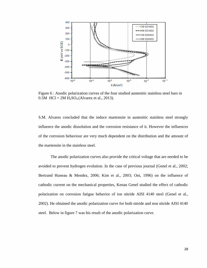
Figure 6 : Anodic polarization curves of the four studied austenitic stainless steel bars in
0.5M HCl + 2M H2SO4 (Alvarez et al., 2013). ................................................................... 28
Figure 7 : Polarisation curves of AISI 4140 steel in deaerated 3% NaCl solution for
tempered and ion nitrided specimens. .................................................................................. 29
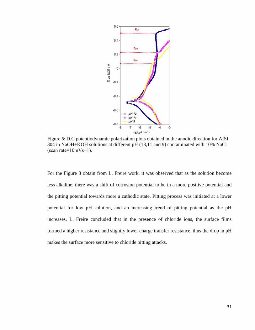
Figure 8: D.C potentiodynamic polarization plots obtained in the anodic direction for AISI
304 in NaOH+KOH solutions at different pH (13,11 and 9) contaminated with 10% NaCl
(scan rate=10mVs−1). .......................................................................................................... 31
Figure 9: Vickers hardness tester ......................................................................................... 34
Figure 10 : Potentiostat ........................................................................................................ 35
Figure 11: Hypobolic Tafel plot ........................................................................................... 36
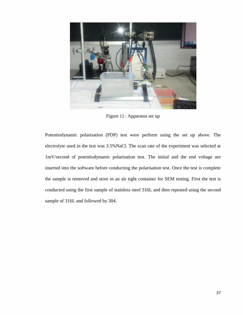
Figure 12 : Apparatus set up ................................................................................................ 37
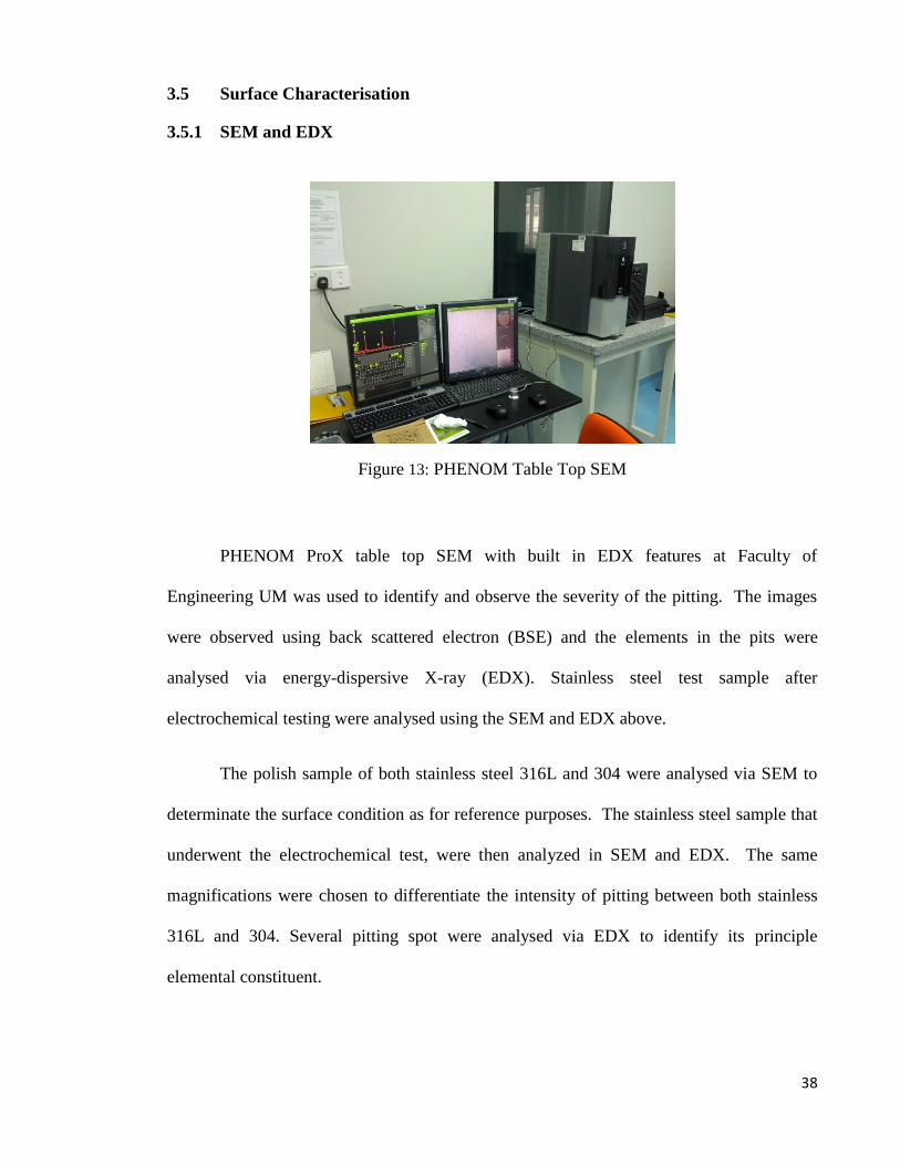
Figure 13: PHENOM Table Top SEM ................................................................................ 38
Figure 14a : Solution anneled structure of 316L at 100X etched with Kalling's No. 2. Figure
14b 500X view on the austenitic grain. ............................................................................... 41
Figure 15a : Stianless steel 304, 100X etched with Kalling's No. 2. Figure15b 500X, view
on the induce maretensitic in austenitic grains. ................................................................... 41
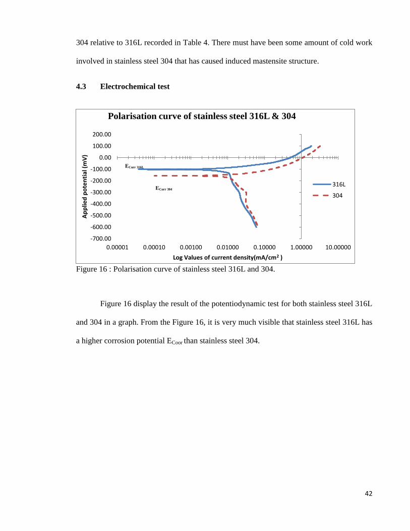
Figure 16 : Polarisation curve of stainless steel 316L and 304. ........................................... 42
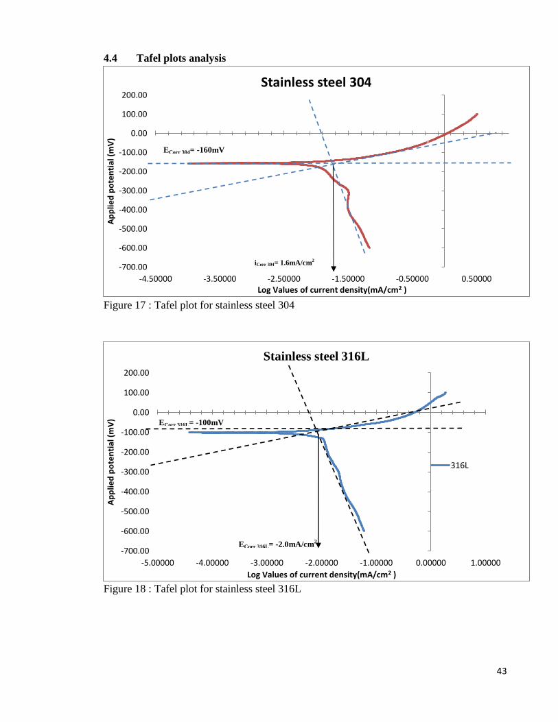
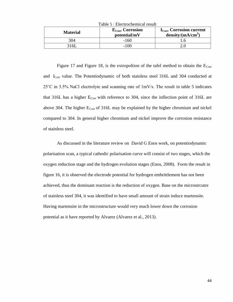
Figure 17 : Tafel plot for stainless steel 304 ........................................................................ 43
Figure 18 : Tafel plot for stainless steel 316L...................................................................... 43
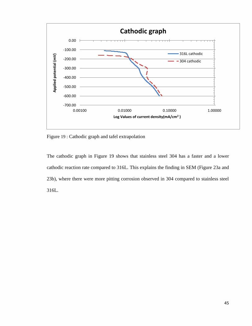
Figure 19 : Cathodic graph and tafel extrapolation .............................................................. 45
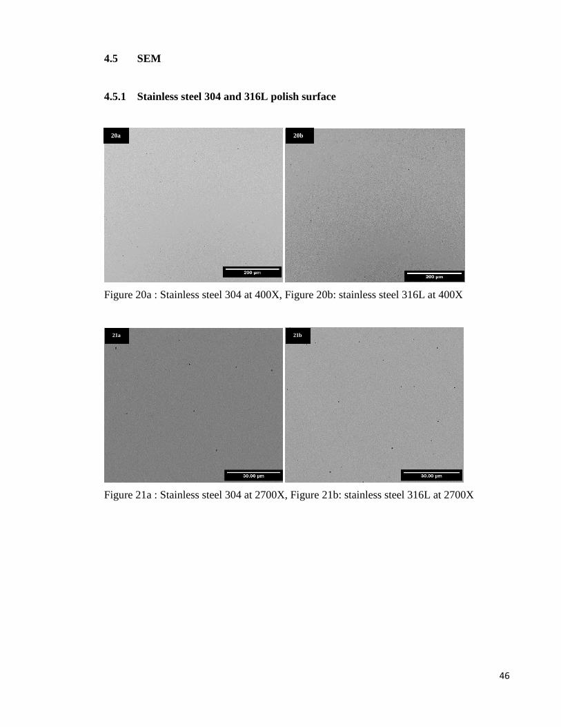
Figure 20a : Stainless steel 304 at 400X, Figure 20b: stainless steel 316L at 400X ........... 46
Figure 21a : Stainless steel 304 at 2700X, Figure 21b: stainless steel 316L at 2700X ....... 46
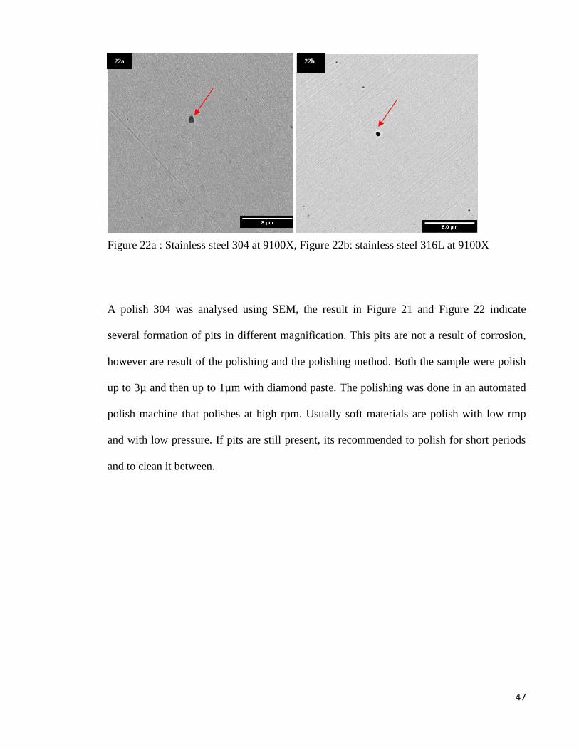
Figure 22a : Stainless steel 304 at 9100X, Figure 22b: stainless steel 316L at 9100X ....... 47
Figure 23a : Stainless steel 304 at 400X several pits were identify , Figure 23b: stainless
steel 316L at 400X, few pits were identify. ......................................................................... 48
Figure 24a: 2700X view on stainless steel 304 pits, Figure 24b: 2700X view on stainless
steel 316L pits. ..................................................................................................................... 48
Figure 25a : 9100X view no stainless steel 304 pit, Figure 25b: 9100X on stainless steel
316L pits. ............................................................................................................................. 49
Figure 26 : EDX spectrum result in the corrosion pit for stainless steel 304....................... 50
Figure 27 : EDX spectrum result in the corrosion pit for stainless steel 316L .................... 50
ix
LIST OF TABLE
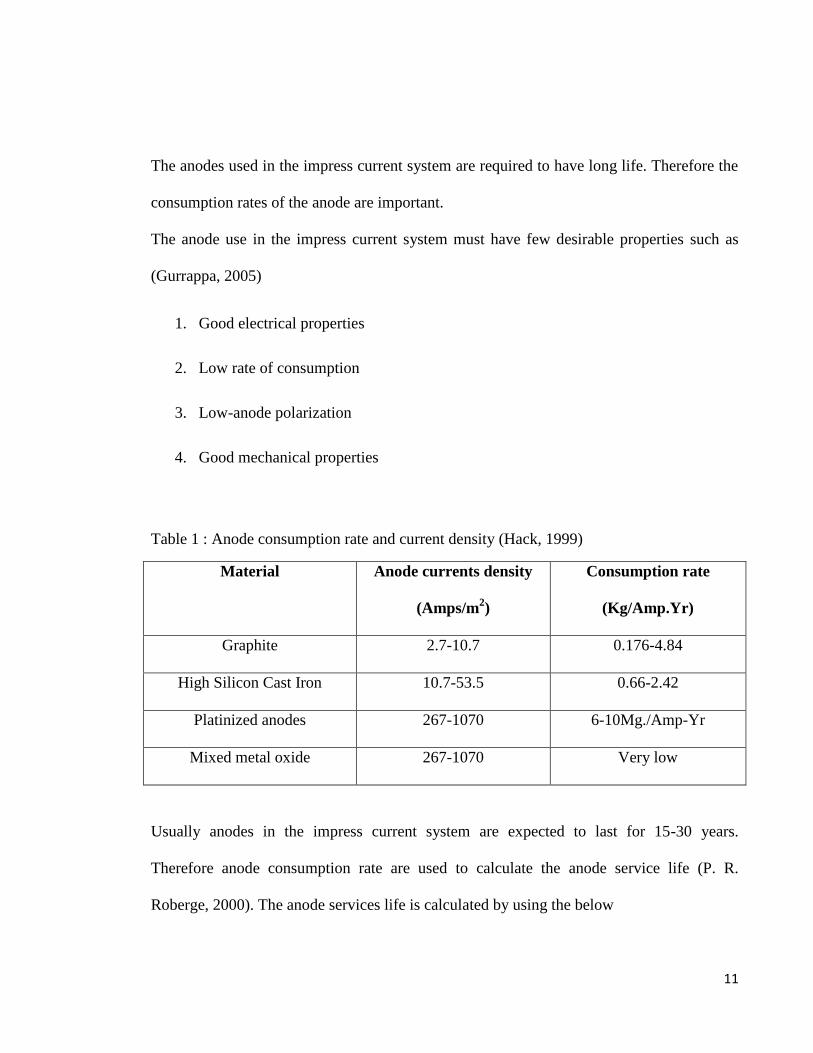
Table 1 : Anode consumption rate and current density (Hack, 1999) ................................. 11
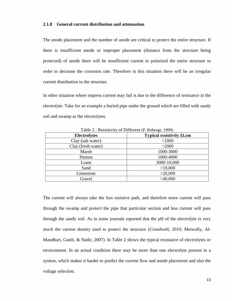
Table 2 : Resistivity of Different (P. Roberge, 1999) .......................................................... 13
Table 3 : Chemical composition of stainless steel 316L and 304 ........................................ 33
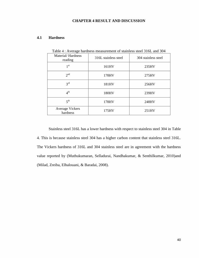
Table 4 : Average hardness measurement of stainless steel 316L and 304 ......................... 40
Table 5 : Electrochemical result ........................................................................................... 44
Table 6 : Quantitative EDX result of the corrosion pits for 304 and 316L stainless steel ... 50
x
LIST OF SYMBOLS AND ABBREVIATIONS
SEM - Scanning Electron Microscopy
EDX - Energy Dispersive X-Ray
ICCP - Impress Current Cathodic Protection
Na - Sodium
Cl - Chlorine
PWHT - Post Weld Heat Treatment
SSRT - Slow Strain Rate
SCC - Stress Corrosion Cracking
Mo - Molybdenum
SEC - Saturated Calomel Electrode
1
CHAPTER 1 INTRODUCTION
1.1 Stainless steel
Stainless steels are highly corrosion resistance steel and iron based alloy that
contain a predominant alloying element of chromium at minimum of 12%. The minimum
amount is required to prevent the formation of rust in an ambient atmosphere. Hence the
designation stainless came about. The added chromium in the steel creates a passive
surface oxide film which protects the underlying metal from corrosion. The oxides forms
and heals itself in the presence of oxygen.
The corrosion resistance of stainless steel may also be enhanced by the addition of nickel
and molybdenum.
Stainless steel are classified by their constituent of the microstructure such as
austenitic, martensitic, ferritic or duplex (consist of both austenitic and ferritic). In addition
to the classification is the precipitation-hardenable (PH) stainless steel. This type of
stainless steel is based on the type of heat treatment used rather than the microstructure.
Austenitic stainless steel are the common stainless steel in the market and they made up the
majority of it.
Stainless steel are susceptible to pitting corrosion. Pitting corrosion is a localized type of
corrosion which is caused by the break do of the passive oxide layer. Pitting corrosion is an
autocatalytic process, where in the vicinity of pit it produce condition that both stimulate
and necessary for continuing its anodic reaction in the pit. Researches has indicate that the
2
addition of molybdenum in austenitic stainless steel increases the resistance of pitting in
austenitic stainless steel (ASM, 2000; William Smith, 1993).
Austenitic stainless steel are also venerable to stress corrosion cracking and intregranular
corrosion. When austenitic stainless steel is heated to a temperature range of 510-780˚C,
they become sensitized to intergranular corrosion (Balasubramaniam, 2010; William Smith,
1993). Intergranular corrosion occurs due to the depletion of chromium adjacent to the
grain-boundary. In the temperature range indicated, chromium will be removed from solid
solution and will be precipitate as Cr23C6 at the grain boundary. This will occur when
carbon content in stainless steel is higher than 0.02%. Since there will be a different
polarity present at the grain boundary and the region adjacent to the grain boundary
corrosion will occur.
1.2 Problem statement
Cathodic protection is a common method of protecting steel or metal structure that
is submerged underground or in an electrolyte via supplying electrons to the structure
(Hack, 1999). Supplying electron or cathodic current to the metal structure being protected
will eventually bring down the corrosion rate to very low rates (Fontana, 1986; P. R.
Roberge, 2000).
There are two method of supplying the electron to the structure being protected, one is
known as a sacrificial anode, where a more electropositive metal (reactive metal) are
attached to the steel structure (P. R. Roberge, 2000).
The other method is impress current cathodic protection, where current is supplied directly
to the structure being protected. Both methods have its benefit and its disadvantages.
3
In the research we will be focusing more on impress current cathode protection where
cathodic current is supplied by a potentiostat.
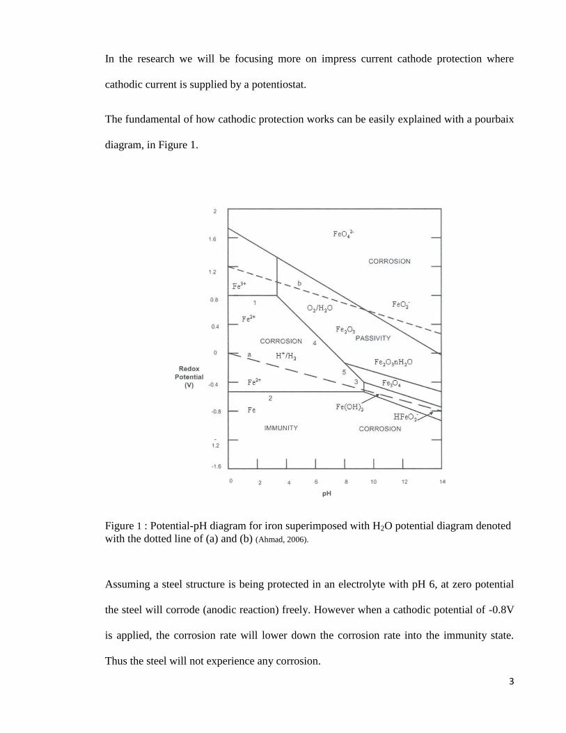
The fundamental of how cathodic protection works can be easily explained with a pourbaix
diagram, in Figure 1.
Figure 1 : Potential-pH diagram for iron superimposed with H2O potential diagram denoted
with the dotted line of (a) and (b) (Ahmad, 2006).
Assuming a steel structure is being protected in an electrolyte with pH 6, at zero potential
the steel will corrode (anodic reaction) freely. However when a cathodic potential of -0.8V
is applied, the corrosion rate will lower down the corrosion rate into the immunity state.
Thus the steel will not experience any corrosion.
4
As good as it sounds this system as a small pit fall. In condition where there is too high
cathodic potential (phenomena know as over-potential) supplied to the structure being
protected, the rate hydrogen evolution increases. The hydrogen gas released on the structure
will induce many negative effects such as hydrogen embrittleement and brittle failure of the
structure being protected, which are considered a catastrophic failure with relative to a
general corrosion.
The phenomenon of over-potential usually occurs in an impress current cathodic protection
system, this is due to the current supplied are powered by an external sourced. Many
factors are considered before applying and selecting the voltage for the impress current
system. For example factors such as anode placement and distance from the structure being
protected, electrolyte resistance, type of coating on the structure, and surface area of the
structure being protected.
This research paper is focused on a small aspect on investigating the phenomena of over-
potential of stainless steel in 3.5% of sodium chloride solution.
1.3 Research Objective and aims
It is well known that by applying cathodic current to a structure, the corrosion rate is
drastically reduced (Barbalat et al., 2013). However in the literature review it will be
revealed that in spite of cathodic current applied to structure, in certain cases, it promotes
hydrogen embrittlement and pitting corrosion. As such, the project paper seeks to
understand the nature of cathodic protection of stainless steel and the occurrence of pitting.
5
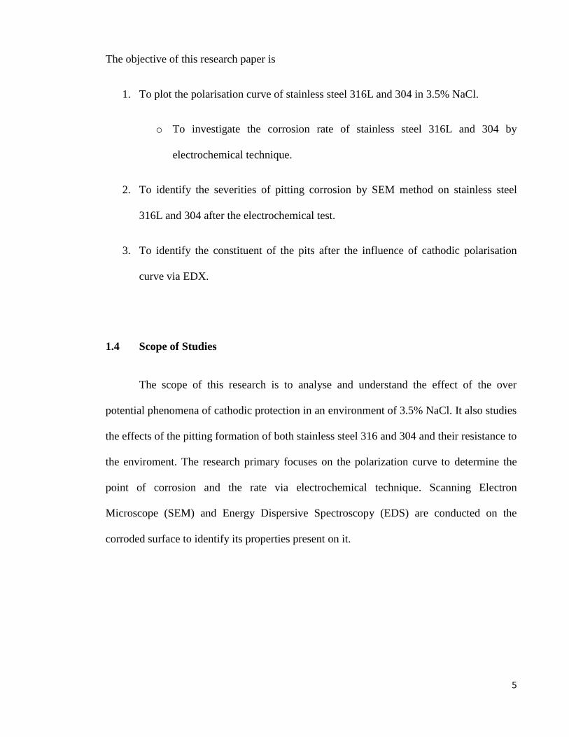
The objective of this research paper is
1. To plot the polarisation curve of stainless steel 316L and 304 in 3.5% NaCl.
o To investigate the corrosion rate of stainless steel 316L and 304 by
electrochemical technique.
2. To identify the severities of pitting corrosion by SEM method on stainless steel
316L and 304 after the electrochemical test.
3. To identify the constituent of the pits after the influence of cathodic polarisation
curve via EDX.
1.4 Scope of Studies
The scope of this research is to analyse and understand the effect of the over
potential phenomena of cathodic protection in an environment of 3.5% NaCl. It also studies
the effects of the pitting formation of both stainless steel 316 and 304 and their resistance to
the enviroment. The research primary focuses on the polarization curve to determine the
point of corrosion and the rate via electrochemical technique. Scanning Electron
Microscope (SEM) and Energy Dispersive Spectroscopy (EDS) are conducted on the
corroded surface to identify its properties present on it.

6
CHAPTER 2 LITERATURE REVIEW
This chapter give a comprehensive view on the cathodic protection, electrochemical
measurement of corrosion rate and stainless steel pitting.
2.1 Cathodic Protection
2.1.1 Basic Reaction (Equation)
Cathodic protection is achieved by supplying electrons or cathodic current to the
metal structure to be protected. Humphrey Davy used was one of the first to used cathodic
protection on British naval ship in 1824 (Ahmad, 2006; Fontana, 1986). The principle of
cathodic protection can be explained via electrochemistry. For example a typical metal M
in an acidic solution will corrode with the evolution of hydrogen gas as below (P. Roberge,
1999).
Anode ∶ M → Mn+ + ne−
Cathode ∶ 2H+ + 2e− → H2
From the above electrochemical equation we understood that the addition of electron or
negative current will suppress the degradation of metal M, and with an excess of electron, it
might caused the evolution of hydrogen. Therefore using the basic method of
electrochemistry, the cathodic protection technology has been developed.
There are two method of applying the cathodic protection principle. The first method is via
sacrificial anode and the other is via Impress Current Cathodic Protection (ICCP). For an
example a steel structure that wants to be protected is made a cathode by attaching it to an
7
anode in an electrolyte (which can be water or soil). Cathodic current are applied in the
structure, which reduce the corrosion rate thus bring the metal structure closer to an
immune state (P. Roberge, 1999).
2.1.2 Sacrificial Anode
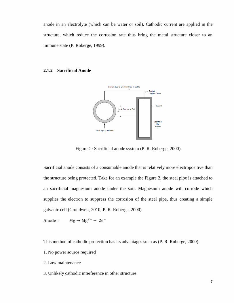
Figure 2 : Sacrificial anode system (P. R. Roberge, 2000)
Sacrificial anode consists of a consumable anode that is relatively more electropositive than
the structure being protected. Take for an example the Figure 2, the steel pipe is attached to
an sacrificial magnesium anode under the soil. Magnesium anode will corrode which
supplies the electron to suppress the corrosion of the steel pipe, thus creating a simple
galvanic cell (Crundwell, 2010; P. R. Roberge, 2000).
Anode ∶ Mg → Mg2+ + 2e−
This method of cathodic protection has its advantages such as (P. R. Roberge, 2000).
1. No power source required
2. Low maintenance
3. Unlikely cathodic interference in other structure.
8
4. Relatively low risk of overprotection
The down falls of this relatively simple system are (Hack, 1999; P. Roberge, 1999).
1. Limited power and current output.
2. Large structure or high resistivity environment may require a large number of anodes.
3. Anodes are required to be replaced frequently under high current system.
4. In some system, anode may increase the weight of the structure if directly attached.
2.1.3 Anode requirements in a sacrificial system
The anode in this system are required to
1. Have a more electropositive or higher position in the E.M.F series relative to the
structure being protected.
2. Have enough driving voltage to protect the structure in a particular electrolyte.
3. Have a stable operating potential over a range of current outputs.
4. Have the ability to consistently deliver high capacity of current per unit mass of
material consumed, trough out his lifetime.
The common anode that used in this sacrificial anode system are magnesium, zinc and
aluminium. Magnesium anodes are preferred than the rest because of its high current output
(Ahmad, 2006; Fontana, 1986).
9
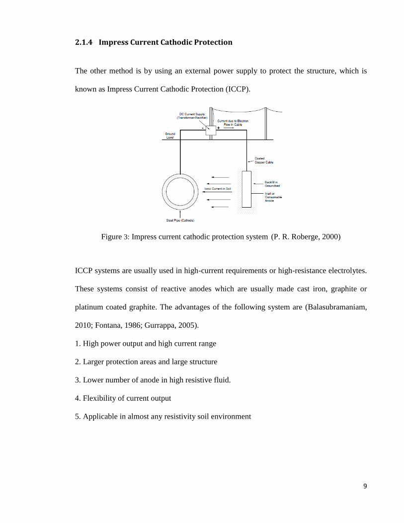
2.1.4 Impress Current Cathodic Protection
The other method is by using an external power supply to protect the structure, which is
known as Impress Current Cathodic Protection (ICCP).
Figure 3: Impress current cathodic protection system (P. R. Roberge, 2000)
ICCP systems are usually used in high-current requirements or high-resistance electrolytes.
These systems consist of reactive anodes which are usually made cast iron, graphite or
platinum coated graphite. The advantages of the following system are (Balasubramaniam,
2010; Fontana, 1986; Gurrappa, 2005).
1. High power output and high current range
2. Larger protection areas and large structure
3. Lower number of anode in high resistive fluid.
4. Flexibility of current output
5. Applicable in almost any resistivity soil environment
10
The limitation of this ICCP:
1. External power supply is required and running cost of external power consumption is
required.
2. Higher risk of overprotection damage
3. More complex than sacrificial anode system
Blackfill are always used to increase the effective anode size and to lower the resistance of
the soils. A good conductivity of anode to the surrounding environment will reduce the
anode consumption.
There are many types of anode used in ICCP such as, graphite anode, platinised anode,
mixed-metal anode, cast iron or scrap steel.
2.1.5 Type of anodes
Inert anodes are used for impress current cathodic protection because the difference of
potential are supplied by an external current supply. Therefore this system does not require
an anode that has a higher electronegativity. In impress current cathodic protection inert
anode used are (Gurrappa, 2005)
1. Mild steel
2. Cast iron
3. Graphite
4. Platinized titanium anodes
5. Mixmetal oxide anode
11
The anodes used in the impress current system are required to have long life. Therefore the
consumption rates of the anode are important.
The anode use in the impress current system must have few desirable properties such as
(Gurrappa, 2005)
1. Good electrical properties
2. Low rate of consumption
3. Low-anode polarization
4. Good mechanical properties
Table 1 : Anode consumption rate and current density (Hack, 1999)
Material Anode currents density
(Amps/m2)
Consumption rate
(Kg/Amp.Yr)
Graphite 2.7-10.7 0.176-4.84
High Silicon Cast Iron 10.7-53.5 0.66-2.42
Platinized anodes 267-1070 6-10Mg./Amp-Yr
Mixed metal oxide 267-1070 Very low
Usually anodes in the impress current system are expected to last for 15-30 years.
Therefore anode consumption rate are used to calculate the anode service life (P. R.
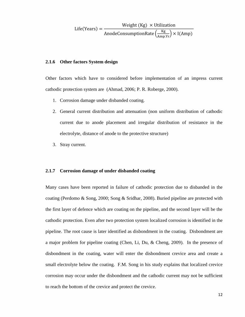
Roberge, 2000). The anode services life is calculated by using the below
12
Life(Years) =Weight (Kg) × Utilization
AnodeConsumptionRate (Kg
Amp.Yr) × I(Amp)
2.1.6 Other factors System design
Other factors which have to considered before implementation of an impress current
cathodic protection system are (Ahmad, 2006; P. R. Roberge, 2000).
1. Corrosion damage under disbanded coating.
2. General current distribution and attenuation (non uniform distribution of cathodic
current due to anode placement and irregular distribution of resistance in the
electrolyte, distance of anode to the protective structure)
3. Stray current.
2.1.7 Corrosion damage of under disbanded coating
Many cases have been reported in failure of cathodic protection due to disbanded in the
coating (Perdomo & Song, 2000; Song & Sridhar, 2008). Buried pipeline are protected with
the first layer of defence which are coating on the pipeline, and the second layer will be the
cathodic protection. Even after two protection system localized corrosion is identified in the
pipeline. The root cause is later identified as disbondment in the coating. Disbondment are
a major problem for pipeline coating (Chen, Li, Du, & Cheng, 2009). In the presence of
disbondment in the coating, water will enter the disbondment crevice area and create a
small electrolyte below the coating. F.M. Song in his study explains that localized crevice
corrosion may occur under the disbondment and the cathodic current may not be sufficient
to reach the bottom of the crevice and protect the crevice.
13
2.1.8 General current distribution and attenuation
The anode placement and the number of anode are critical to protect the entire structure. If
there is insufficient anode or improper placement (distance from the structure being
protected) of anode there will be insufficient current to polarized the entire structure in
order to decrease the corrosion rate. Therefore in this situation there will be an irregular
current distribution to the structure.
In other situation where impress current may fail is due to the difference of resistance in the
electrolyte. Take for an example a buried pipe under the ground which are filled with sandy
soil and swamp as the electrolytes.
Table 2 : Resistivity of Different (P. Roberge, 1999)
Electrolytes Typical resistivity Ω.cm
Clay (salt water) <1000
Clay (fresh water) <2000
Marsh 1000-3000
Humus 1000-4000
Loam 3000-10,000
Sand >10,000
Limestone >20,000
Gravel >40,000
The current will always take the less resistive path, and therefore more current will pass
through the swamp and protect the pipe that particular section and less current will pass
through the sandy soil. As in some journals reported that the pH of the electrolyte is very
much the current density used to protect the structure (Crundwell, 2010; Metwally, Al-
Mandhari, Gastli, & Nadir, 2007). In Table 2 shows the typical resistance of electrolytes or
environment. In an actual condition there may be more than one electrolyte present in a
system, which makes it harder to predict the current flow and anode placement and also the
voltage selection.
14
Liu Zhiyong studies the significant of non-stable cathodic polarization effect on the SSC of
X80 pipeline steel (Zhiyong, Zhongyu, Xiaogang, Cuiwei, & Yunying, 2014). In his
finding he concluded that non-stable polarization will enhance both the anodic dissolution
and cathodic reaction which results in hydrogen evolution. The non-stable cathodic
polarization will firstly discharge the process of the electric double layer and accelerate the
mass transport step, which enhance the cathodic reaction of hydrogen evolution. Secondly
due to localized anodic dissolution may occur under a non-stable cathodic polarization
(Zhiyong et al., 2014).
2.1.9 Stray current
Stray current in fact does not cause much damage to the structure being protected however,
it causes damage to the nearby structure. Stray current is current flowing in the electrolyte
from an external source like a railways power line (Hack, 1999; P. Roberge, 1999). Stray
current tends to enter a buried structure in a particular location and exits in another location.
In location where the currents exits the structure, is where the most amount of damage
corrosion damage occurs.
2. 2 Impress Current Cathodic Protection Failures
Cathodic protection has it down fall in condition where the structures being protected are
excessively negative potential. This will result in hydrogen evolution on the cathode
surface which result in hydrogen embrittlement of steel. This will cause the structure to
lost its mechanical properties and lead to catastrophic failure (Barbalat et al., 2013; Cheng
& Niu, 2007).
15
ICCP is used in protecting large areas of structure, pipe or concrete underground or in
water. One of the important criteria in ICCP is to know how much current to apply on the
steel structure to polarise in order to protect it. The protection is applied when the potential
is about -850mV with a reference to copper/copper sulphate reference electrode. The
application of excessive negative potential leads to hydrogen generation at the protected
structure. This will lead to hydrogen embrittlement of the structure, thus reducing the
mechanical properties (Cheng & Niu, 2007; B. Huneau & Mendez, 2003; Bertrand Huneau
& Mendez, 2006; Lindley & Rudd, 2001).
Seong-Jong Kim conducted a electrochemical studies of cathodic protection of steel
in marine structure. He suggested that imposing high levels of impress cathodic current can
result in hydrogen embrittlement which can result in failure in high-strength steel,
particularly at welds. In his research he investigated the electrochemical effects of post
weld heat treatment (PWHT) of high strength steel under slow strain rate (SSRT) test using
sacrificial anode in natural sea water. In his finding via SEM fractography, he identified the
specimen has transgranular fracture pattern when the potential applied was below -854mV
(SCE) and a dimple pattern with ductile fracture when -770~-850mV (SCE) was applied.
Therefore, the optimum cathodic protection range between -770-850mV was not causing
any hydrogen embrittelement (Kim, Okido, & Moon, 2003).
Study conducted by A.Oni proves that excessive impress-current cathodic
protection of dual phase low alloy steel influence the tensile and the yield strength of steel
(Oni, 1996). In his experiment he had selected a dual phase steel with a profile of tensile
test dimension and immersed it in an electrochemical cell made from trifluoroethene resins
with pressure fitting. The specimens were subjected to tensile loads at applied cathodic
potentials ranging from -800mV to -1400mV SCE at strain rate of 1.4x10⁻⁶
/s until it
16
fractured. A resilience modulus graph and tensile strength against the applied cathodic
protection was plotted. From the graph, it is visible that the tensile strength increased as the
cathodic potential increased and decreased rapidly when the applied potential reached -
1100mVSCE. It is believed that ICCP resulted in hydrogen generation, thus hydrogen-metal
interaction which occurred on the dual phase steel. The hydrogen atom entered into the
lattice structure, thus increasing the dislocation within the matrix. Therefore, more stress
are required to cause dislocations which explain this increase in strength. He concluded that
the interaction resulting from hydrogen entry into the interstitial sites in the lattice structure
is due to the application of excessive of cathodic current would have significant influence
in the strength behaviour of metal.
In a similar study conducted by Seok-Ki Jang, studied on overpotential phenomena
of stainless steel 304, 316, 630 estimated that hydrogen embrittelemt occurred at
overpotential of -0.912V, -0.912V, and -1.07V for the respective stainless steel (Jang, Han,
& Kim, 2009). In this test he used stainless steel 304, 316 and 630 that are most commonly
used as shaft material, structure beam. The Cathodic potential was applied at room
temperature using an electrochemical apparatus to plot out a cathodic polarization curve.
From the cathodic polarisation curve, information such as activation polarization and
concentration polarization for hydrogen gas generation were extracted for each steel
sample.
Corrosion potential and current density were determined using Tafel equation and analysis.
∆V = Ax ln ( ii0
)
Where V is the overpotential, A is the Tafel slope, and i is the current density (A/m2) and io
is the exchange current density.
17
When there was an over potential of -0.912V for 304 stainless steel, there was hydrogen
evolution occurred and an evidence of pitting corrosion was evident on the sample. Seok-Ki
said there was a possibility that this stainless steel would failure under stress corrosion
cracking (SCC) due to pitting caused by the destruction of the chromium oxide passive
layer on the steel.
Hydrogen cracking have been attributed to several cases of supermartensitic
stainless steel where the source of hydrogen was from the cathodic protection system
(Solheim & Solberg, 2013). In an ideal condition, the over potential of the cathode can be
controlled by varying the applied current. However in actual environmental condition there
are many factors to be considered. For example steel pipelines which are buried under
ground that are being protected by impress current method are influenced by many factors
such as, conductivity of the soil, aeration, permeability, acidity, humidity, sulfates
concentration, chlorides concentration, presence of biological species, stray current, and
anode placement in ICCP system (Metwally et al., 2007; Solheim & Solberg, 2013) .
In theory, current for cathodic protection system are determine in consideration of
the conductivity of the soil or fluid (V=IR) and the surface area of the structure being
protected (Fontana, 1986). Therefore, the current density is an important factor to
determine the effectiveness of the protection of the cathodic system. Too much of current
density may cause the generation of hydrogen in the cathode, if too little it may cause
insufficient protection of the structure. Alternating current has a negative effect on cathodic
protection. Study conducted by L.Y Xu on the effect of alternating current on cathodic
protection on pipelines, described that the effectiveness of cathodic protection will drop and
increased the corrosion rate (L. Y. Xu, Su, & Cheng, 2013).
18
Z.Y.Liu investigated the relationship of stress corrosion cracking (SCC) , and
hydrogen embritelement of X70 pipeline steel under cathodic current in an near-neutral
pH of NS4 solution with slow strain rate tensile (SSTT) with various cathodic potential
(Liu, Li, & Cheng, 2012a). The X70 steel sample had been subjected the with strain rate of
5x10⁻⁷
/s under 1200mV,-1030mV,-925mV,-890mv,-850mV and -750mV until it fractured.
The fracture surface was investigate under scanning electron microscope (SEM). While
conducting the experiment, a potentiodynamic polarization curves was measured to
investigate the electrochemical corrosion behaviour of the steel in the NS4 solution as the
effect of the occurrence of SCC. Z.Y.Liu believed that the applied potential has a large
impact on the failure mechanism of the X70 steel. When the applied potential was negative,
the steel experience SCC under hydrogen embrittlement mechanism. While the applied
potential was more positive, SCC was under anodic dissolution. He concluded that when a
steel is in a critical potential range, the steel will be in a non-equilibrium electrochemical
state, and anodic dissolution would occur under cathodic polarization potential. This will
contribute to the SCC under a combine effect of hydrogen embrittlement and anodic
dissolution.
In another study Z.Y.Liu preformed an experiment to understand the occurrence of
pitting corrosion of pipeline carbon steel under cathodic protection (Liu, Li, & Cheng,
2012b). In many cases, the SCC of pipeline failure was initiated from pitting corrosion
(Dong, Fu, Li, & Cheng, 2008). Z.Y. Lui agrees that the knowledge behind the mechanism
of pitting corrosion on a cathodic protected structure is lacking. In his experiment, this
pitting corrosion were investigated with two technique which are, the square wave
polarization and localized electrochemical impedance spectroscopy measurement. Using
the technique above, he found that pitting corrosion could occur at two conditions under
19
cathodic protection. The first was where the steel experience a potential fluctuation during
cathodic protection, thus reversed potential field was generated locally at the surface defect
which resulted of localized pitting. The second was where the anodic reaction could take
place at localized area to initiate pitting corrosion (Liu et al., 2012b). In an earlier
publication Z.Y.Liu, explain that fluctuation polarization generated on the steel electrode
would disturbed the local double-charge layer structure (Liu, Li, & Cheng, 2011). Under
these circumstances there would be temporary anodic potential field, resulting in a local
anodic dissolution to nucleate pits. Local anodic dissolution which results in pits may occur
under an unstable cathodic polarization (Liu et al., 2011, 2012a).
Research conducted by M. Javidi on the mechanism of stress corrosion cracking of
API 5LX52 steel in near–neutral & high pH environment under cathodic protection,
suggested that there are two dominant mechanisms for SCC. When a pipeline is buried
underneath the ground, it experience two forms of SCC one is at high pH SCC and near-
neutral pH SCC (Cheng & Niu, 2007; M. C. Li & Cheng, 2008). The high pH SCC of
carbon steel occur high concentration of biacarbonate at high pH(9-11). This type of SCC
have a typical characteristics of intregranular fracture, small amount of lateral corrosion of
crack wall and sharp crack tip (Javidi & Bahalaou Horeh, 2014). The rupture of passivation
film from the crack tip and dissolution at the grain boundary contributed to anodic
dissolution which results to high pH SCC. On the other hand the near-neutral pH SCC are
attributed to hydrogen, carbon dioxide which often occur under disbanded of coting of the
buried pipelines. This from of SCC is characterise by transgranular crack, with quasi-
cleavage and branching of the fracture surface, and lateral corrosion on crack wall (Eslami
et al., 2011; D. G. Li, Wang, Chen, & Liang, 2014; Mustapha, Charles, & Hardie, 2012).

20
Under cathodic protection, the API 5LX52 steel would still fail via stress corrosion
cracking mechanisms. The dominating factors that promote these mechanisms are caused
by the first the stress experience by the steel and second the applied cathodic current. M.
Javidi concluded that the mechanisms of stress corrosion cracking were affected with the
applied cathodic potentials. Therefore it is very important to identify the optimum potential
for any structure that is protected via impress current cathodic protection.
In a failure analysis journal conducted by University of Calgary, This article include
studies of reported case of pipeline failures which covers the effects of cathodic protection
on corrosion corrosion fatigue crack, hydrogen embrittlement under and stress corrosion
cracking of pipeline in service condition (Shipilov & Le May, 2006). A typical lifetime of a
pipeline is determined by the rate of crack propagation. In this literature it pointed out that
cathodic protection increases the crack growth rate, and accelerate the crack growth, which
is due to hydrogen embrittlement caused by enhance hydrogen uptake in the steel. However
there are some date which indicates that the cathodic Protection actually increases banding
fatigue strength. This is attributed to the interstitial hydrogen substitution which increase
the fatigue limit (Shipilov & Le May, 2006). It is more evident that cathodic current has a
significant impact on the mechanical properties of the steel structure being protected and
also increases the propagation rate of crack (Oni, 1996; Shipilov & Le May, 2006).
In a similar study conducted by B.Hubeau, on the fatigue behaviour of a high
strength steel in vacuum in air and 3.5%NaCl solution under cathodic protection suggested
that the cathodic protection condition leads to a reduction of fatigue lives of SE720 steels
compared with vacuum (B. Huneau & Mendez, 2003). Both crack initiation points and
propagation stage are calculated and observed via SEM. The highest fatigue was measured
in vacuum condition, followed by air and the lowest fatigue life was is in NaCl solution.
21
The number of fatigue cycle recorded in vacuum, air and NaCl with loads of σmax 450MPa
are 150,000cycle, ~50,000cycle and ~ 10,000 cycles respectively. The reductions of fatigue
life in air are attributed to the gaseous environment, water vapour and hydrogen effect and
oxygen playing a role in the crack initiation stage. In the NaCl solution both reduction of
crack initiation and propagation stage was observed with reference to vacuum condition. In
the NaCl solution hydrogen product are attributed form the cathodic protection. The
hydrogen contribute to strong embrittlement of fracture surface which characterized by
brittle intergranular crack observed in SEM. Bertrand Huneau also confirms the fact there is
a drop fatigue strength of high strength steel in saline solution with cathodic protection, as
he conducted the similar study with SE720 steel. He concluded that the hydrogen produced
by cathodic protection contributed to the fatigue crack growth rate of the steel. The
embrittlement occur via decohesion between prior austenitic grains or martensite laths
(Bertrand Huneau & Mendez, 2006).
Wenhe Wang conducted studies of crevice corrosion for buried pipeline with disbonded
coating under cathodic protection. He studied the polarization potential,current density, pH
value and dissolve oxygen concentration in the crevice (Wang, Wang, Wang, & Yi, 2014).
The findings of this investigation suggested that the applied cathodic protection may
increases the pH values in the crevice thus increase the rate of corrosion. Cathodic current
are unable to reach the bottom of the crevice and reduce the effectiveness of cathodic
protection. There is always a potential difference exist between the mouth and in section of
the crevice. The normal crevice corrosion mechanisms will take place thus reducing the
oxygen concentration and increase the pH values in crevice with time. This was cause by
potential drop in the crevice due to solution resistance and current dissipation. High CP is
required to achieve corrosion protection at the crevice area due high pH concentration in
22
the crevice. Higher CP will also increase the risk of hydrogen evolution near the mouth of
the crevice (Wang et al., 2014).
In a study conducted by F.Zucchi, on hydrogen embrittlement of duplex stainless
steel under cathodic protection in acidic artificial sea water in the presence of sulphide ion,
discovered that hydrogen embrittlement are stimulated with high sulphide amount and high
voltage of cathodic potential (Zucchi, Grassi, Monticelli, & Trabanelli, 2006). The tests
were conducted with different artificial sea water with 0ppm, 1ppm, 10ppm, 30ppm of
sulphide ions. Sulphide ion concentration of 1ppm coupled with cathodic potential of -
0.9VSCE are sufficient to initiated hydrogen embrittlement in duplex stainless steel. There
was a decrease of percentage of elongation of fracture of duplex stainless steel under air
condition and under acidic artificial sea water form 1-30ppm sulphide ion condition with
increasing voltage. From previous studies it was recorded that the diffusion of hydrogen
atoms through the austenitic phase is much slower than through the ferritic phase (Du, Li,
Chen, Liang, & Guo, 2008; P. Roberge, 1999; Zakroczymski & Owczarek, 2002). From
this investigation, it is understood that increasing current density of a cathodic protection
system in an environment that are rich with sulphide ions not necessary will increase the
corrosion protection, it might have harm effect on the mechanical properties such as
percentage of elongation to the structure (Genel, Demirkol, & Ürgen, 2002; Oni, 1996).
2.3 Stainless Steel
Stainless steel are iron base alloys that contain a minimum of 12% Cr , that forms
an invisible and adherent chromium-rich oxide film that prevent it from rust in unpolluted
atmosphere. The passive oxide film can be breach or broken down in certain aggressive
23
environment condition (Ziaei, Mostowfi, Golestani pour, & Ziaei, 2013). Environment
condition such as the presence of chloride ions and acidic condition may locally breakdown
the passive layer and cause pitting corrosion. Presence of alloying element such as
Molybdenum will increase the pitting corrosion resistant of the stainless steel (Pardo et al.,
2008a, 2008b; P. R. Roberge, 2000; William Smith, 1993). There are four major types of
stainless steels. They are austenitic stainless steel, martensitic stainless steel, ferretic
stainless steel, duplex stainless steel and precipitation-hardened stainless steel.
Stainless steel 316L and 304L are austenitic stainless steel with low carbon content
and its typically used in food industry, pipeline industry (Smith, 1993) . In general the
austenitic stainless steel is resistance to all industrial atmosphere and some acid media.
Stainless steel 316L, has a high corrosion resistance, high strength and high durability and
it are used in many marine application (Cai et al., 2010). However they are susceptible to
intergranular corrosion, stress corrosion cracking and localized corrosion such as pitting
corrosion and crevice corrosion (Cai et al., 2010; Jin, Xie, & Tian, 2012). Intergranular
corrosion of stainless steel results from microstructure changes, where chromium carbides
(Cr3C6 ) precipitated at the grain boundary and cause a depletion of chromium adjacent to
it. The difference in chemistry from the precipitates and the adjacent induce corrosion to
occur (Matula et al., 2001). Most of the corrosion attack on stainless steel starts with small
pits formation and grows via different corrosion mechanisms (Roffey & Davies, 2014;
Ziaei et al., 2013).
S.S Xin conducted an electrochemical corrosion characteristic of 316L stainless
steel in hot concentrated artificial seawater. In this investigation S.S Xin, immersed 316L in
artificial seawater having a pH value of 8.2 at 72˚C for 3200hr (Xin & Li, 2014). Form this
immersion of 316L stainless steel 3 stages are observed, passive stage, transient stage and

24
stable pitting stage. In the passive stage, it involves the dissolution of passive film and the
deposition of salts. At this stage the corrosion potential increase quickly and decrease
gradually at a steady corrosion state due to the salt formation. In the second stage
(transient), the corrosion rate decrease drastically due to the initiation and formation of
pitting corrosion. At the third stage (pitting), the active pits grow which are accompanied
with new formation of pits. Pitting corrosion attacks begin at about 1150hr of immersion,
with stage 1 with deposition of salts. The maximum pit depth was measured at 38µm after a
year of immersion. From this experiment S.S Xin concluded that 316L stainless steel has a
good pitting resistance to hot artificial seawater.
In another studies Congmin Xu, suggested that the pitting resistance of 316L
stainless steel will decrease in the media of sulphate-reducing and iron-oxidizing bacteria.
The corrosion potential, pitting potential and polarization resistance of stainless steel 316L
will decrease in the presence of these bacteria, thus accelerating the pitting corrosion (C.
Xu, Zhang, Cheng, & Zhu, 2008).
However it is well known that corrosion resistance or to be precise pitting resistance
of stainless steel can be improved by the addition on molybdenum (Mo). Addition of
molybdenum into stainless steel increases the general corrosion resistance of the steel.
Molybdenum modifies the passive film composition and the active dissolution by formation
of insoluble oxides (Pardo et al., 2008a, 2008b).
Stainless steel 304 has a slightly lower levels of chromium compare to stainless
steel 316l, it has an average corrosion resistance to sulfuric acid solution. In comparative
study on corrosion behaviour of stainless steel 304 in sulfamic (NH2SO3H) and sulfuric
acid, revealed that the corrosion rate are higher in sulfuric acid than in sulfamic acid in all
condition (Hermas & Morad, 2008).
25
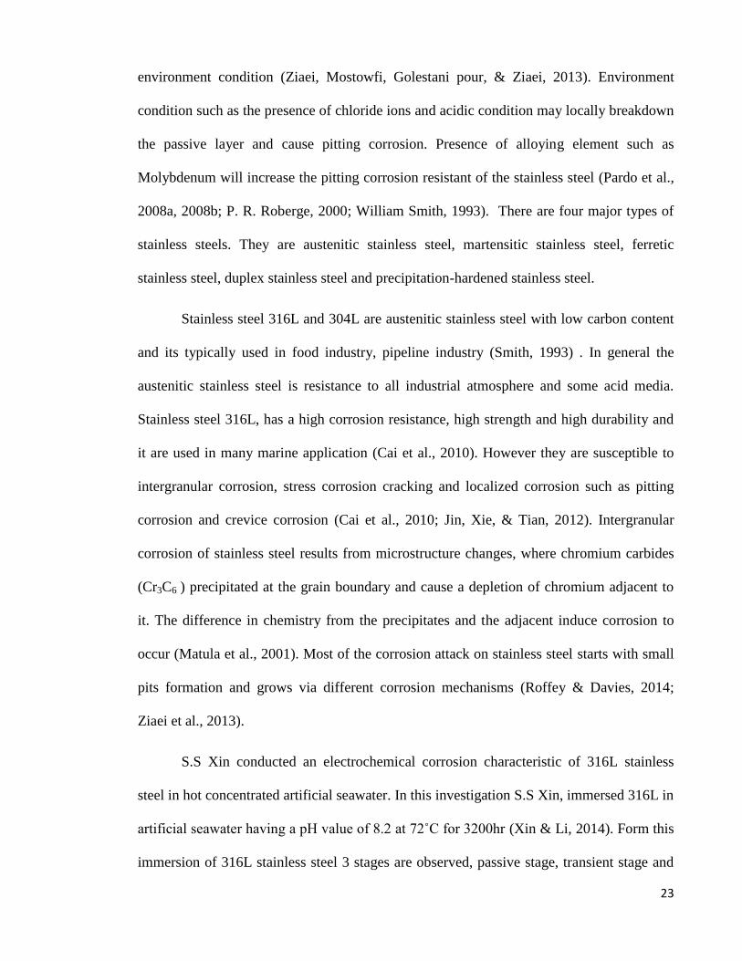
2.4 Pitting Corrosion
Figure 4: Pitting corrosion mechanisms (Ahmad, 2006)
Pitting mechanisms in steel, is shown in the stage below
Stage 1: Fe → Fe2+ + 2e− (anodic)
Stage 2: O2 + 2H2O + 4e− → 4OH− (cathodic)
Stage 3: Fe+Cl− + H2O → FeOH + H+ + Cl−
A pitting corrosion mechanism occurs in three stages. The first stage is the
dissolution of the iron. The continual dissolution of positively charge iron ions in the pits
are electrostatically balanced by cations such as Cl-, OH
- ions. OH
- ions migrate in slower
rate, compare to Cl-
ions which are small (Loto, 2013). The three stages that is the
hydrolysis reaction, where iron chlorides are broke down. That results the formation of iron
hydroxide and hydrochloric acid. The presence of H+
ions and chloride content prevents
repassivation and decreases the pH value in the pits (Ahmad, 2006). This process is an
autocatalytic an it increases with time resulting in more metal dissolution.
26
Pitting corrosion are usually caused by the damage of the passive oxide layer of
stainless steel that expose the stainless steel to aggressive environment. R.T Toto explains
the passive oxide film should be view as a dynamic film (Loto, 2013). The passive film
break down and pit initiation are categorized into 3 main mechanisms. That is film
penetration, film breaking and adsorption. In the penetration stage, migration of Cl- ion
occurs from the electrolyte through the passive layer to the oxide-metal interface by the
influence of high electrical potential. The film breaking mechanisms initiated with cracks,
inclusion, or defect on the passive layer will slowly expose small areas metal surface to the
electrolyte the initiated pits (Ahmad, 2006; Loto, 2013). In adsorption mechanism, there
will be an increase of transfer cations from the passive film to the electrolyte. This process
will result in the thinning and the removal of the passive layer (Loto, 2013).
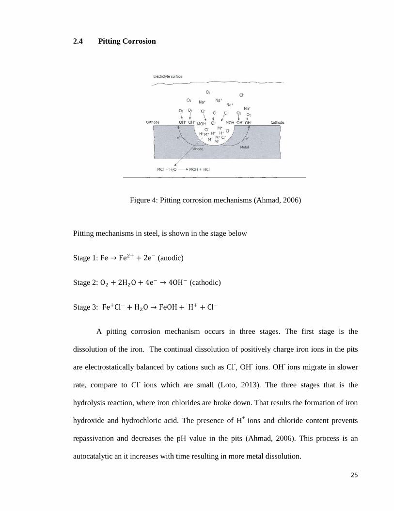
2.5 Polarization Curve for stainless steel
Figure 5: A theoretical cathodic polarisation scan (Enos, 2008)
A cathodic polarisation scans begin at point 1 and ends at point 2. Point A is the
open circuit potential which is the sum of both anodic and cathodic reaction occurring on
the electrode surface are zero. Regions B represent the oxygen reduction reaction and its
Oxygen reduction region
Hydrogen evolution reaction
27
dependent on the pH and dissolve oxygen concentration in the solution. As the applied
potential decrease, there will be no change in reaction at region C, until the potential
becomes sufficiently negative for cathodic reaction to initiated. At point D to E, there will
be a reduction of water, as such hydrogen evolution reaction occurs. Current density may
increases when the is a sufficient driving force (Enos, 2008).
The anodic polarization curve, is an important graph which provide information on
the corrosion rate and the active-to-passive transition (Alvarez, Bautista, & Velasco, 2013).
S.M. Alvarez conducted a study, on anodic dissolution on various type of austenitic
stainless steel in acid medium. He was investigating the influence of induce martensite
microstructure on the corrosion behaviour of stainless steel. The electrochemical test was
conducted by using a Potentiostat, 2M H2SO4 + 0.5M HCL solution as an electrolyte, and
saturated calomel electrode (SCE) as a reference electrode, and stainless steel mesh as a
counter-electrode.
From his result (Figure 6), it is understood that the maximum corrosion rate occur at E= -
200mV. The corrosion rate continues to decrease with increasing E (>-200mV) for all the
stainless steel until it reaches a passive state.
28
Figure 6 : Anodic polarization curves of the four studied austenitic stainless steel bars in
0.5M HCl + 2M H2SO4 (Alvarez et al., 2013).
S.M. Alvarez concluded that the induce martensite in austenitic stainless steel strongly
influence the anodic dissolution and the corrosion resistance of it. However the influences
of the corrosion behaviour are very much dependent on the distribution and the amount of
the martensite in the stainless steel.
The anodic polarization curves also provide the critical voltage that are needed to be
avoided to prevent hydrogen evolution. In the case of previous journal (Genel et al., 2002;
Bertrand Huneau & Mendez, 2006; Kim et al., 2003; Oni, 1996) on the influence of
cathodic current on the mechanical properties, Kenan Genel studied the effect of cathodic
polarization on corrosion fatigue behavior of ion nitride AISI 4140 steel (Genel et al.,
2002). He obtained the anodic polarization curve for both nitride and non nitride AISI 4140
steel. Below in figure 7 was his result of the anodic polarization curve.

29
Figure 7 : Polarisation curves of AISI 4140 steel in deaerated 3% NaCl solution for
tempered and ion nitrided specimens.
The sample that is not nitride (quenched and tempered), shows no visible active-to-passive
transition, unlike the nitrided sample. The non-nitrided sample continues to corrode with
higher current density with increase of electrode potential.
On the other hand the nitrided sample, show a decrease in current density when the
electrode potential was about -900mV. At this stage the vertical line in the graph represents
the passivation, where the corrosion current density drop. Increasing the electrode potential
above -600mV, destroy the passive film and thus increase the corrosion rate. Genel selected
three cathodic potentials which are from the passive, cathodic and the over-chatodic region
of anodic curve to conduct the fatigue test in 3%NaCl. Potential -750mV which lies within
the passive line, -1080mV potential that is within the cathodic line and -1500mV the over-
cahtodic region.
Transpassive
Over potential
Passive
30
The result of the fatigue show that the -750mV was insufficient to protect the steel,
thus corrosion occurred and the fatigue strength reduced. At -1080mV its showed the best
result of corrosion protection and increase in fatigue strength. On the negative side potential
of -1500mV displays hydrogen evolution during the test, and a drastic decrease in fatigue
strength.
Put it into perspective, if an impress current cathodic protection is applied on AISI
4140 steel with a potential of -1500nV in a 3%NaCl environment it would eventually fail
via hydrogen embrittlement. However, if there is a change in the electrolyte concentration
in the soil, or change in distance of anode placement this current may not cause hydrogen
evolution on the steel. Therefore it is curtail to identify variable in the environment to select
the optimum potential.
L. Freire had conducted a study of electrochemical behaviour of stainless steel 304
in different solutions of pH (pH9, pH10, pH13) with the presence of chloride ions (Freire,
Carmezim, Ferreira, & Montemor, 2011). His aim was to study the passivation and
passivation breakdown of stainless steel 304 in different electrolyte. Results show that pH
has a large impact in the formation of film resistance, charge transfer and thus the anodic
dissolution.
31
Figure 8: D.C potentiodynamic polarization plots obtained in the anodic direction for AISI
304 in NaOH+KOH solutions at different pH (13,11 and 9) contaminated with 10% NaCl
(scan rate=10mVs−1).
For the Figure 8 obtain from L. Freire work, it was observed that as the solution become
less alkaline, there was a shift of corrosion potential to be in a more positive potential and
the pitting potential towards more a cathodic state. Pitting process was initiated at a lower
potential for low pH solution, and an increasing trend of pitting potential as the pH
increases. L. Freire concluded that in the presence of chloride ions, the surface films
formed a higher resistance and slightly lower charge transfer resistance, thus the drop in pH
makes the surface more sensitive to chloride pitting attacks.
32
2.6 New technology for cathodic protection
In recent times there a major improvement in corrosion prevention for metal and
steel. It is a common to reduce corrosion attack by a typical protection of organic coating
and the common sacrificial anode and impress current cathodic protection as discussed
previously (Lei, Liu, Zhou, Feng, & Du, 2013). However the protection method such as
sacrificial anode and ICCP, has a limited life time due to the anode deterioration. Ynan and
Tsujikawa suggested a new concept of photogenerated cathodic protection layer (Yuan &
Tsujikawa, 1995). Later in the industry Park, was able to developed a method using a
semiconductor TiO2-based photoelectrochemical to be a photoanode (subsutitue for
sacrificial anode) for corrosion prevention (Park, Kim, & Choi, 2001, 2002). Now TiO2
films are used as photoanodes for cathodic protection of metals.
In a recent studies conducted by Caixiz Lei, on photo generated cathodic protection
of stainless steel by liquid phase deposited sodium polyacrylate/TiO2 hybrid films
suggested that addition of sodium polyacrylate improve the photochemical respond of TiO2
(Lei et al., 2013). In his research he prepared sodium polyacrylate/TiO2 hybrid films by
liquid phase deposited method. The hybrid films were co-doped with elements of nitrogen
and fluorine which stimulate the respond to visible light. This new hybrid film could
provide sufficient negative photopotential for the cathodic protection of 304 stainless steel.
33
CHAPTER 3 METHODOLOGY
3.1 Material
3.1.1 Sample and solution preparation
Stainless steel 316L and 304 sourced from a local supplier and was manufactured in
Korea and India respectively. The sample was cut into 10mm thickness and was mounted.
After the mounting, a small section was drilled and a copper wire was attached to the
stainless steel sample.
Austenitic stainless steel are generally non hardenable via heat treatment and therefore are
used in annealed condition. Below are the typical chemical compositions of both the
stainless steel
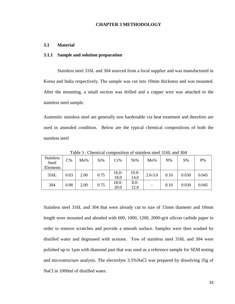
Table 3 : Chemical composition of stainless steel 316L and 304 Stainless
Steel
/Elements
C%
Mn%
Si%
Cr%
Ni%
Mo%
N%
S%
P%
316L 0.03 2.00 0.75 16.0-
18.0
10.0-
14.0 2.0-3.0 0.10 0.030 0.045
304 0.08 2.00 0.75 18.0-
20.0
8.0-
12.0 - 0.10 0.030 0.045
Stainless steel 316L and 304 that were already cut to size of 15mm diameter and 10mm
length were mounted and abraded with 600, 1000, 1200, 2000-grit silicon carbide paper in
order to remove scratches and provide a smooth surface. Samples were then washed by
distilled water and degreased with acetone. Tow of stainless steel 316L and 304 were
polished up to 1µm with diamond past that was used as a reference sample for SEM testing
and microstructure analysis. The electrolyte 3.5%NaCl was prepared by dissolving 35g of
NaCl in 1000ml of distilled water.
34
3.2 Hardness test
3.2.1 Micro Vickers Hardness Tester
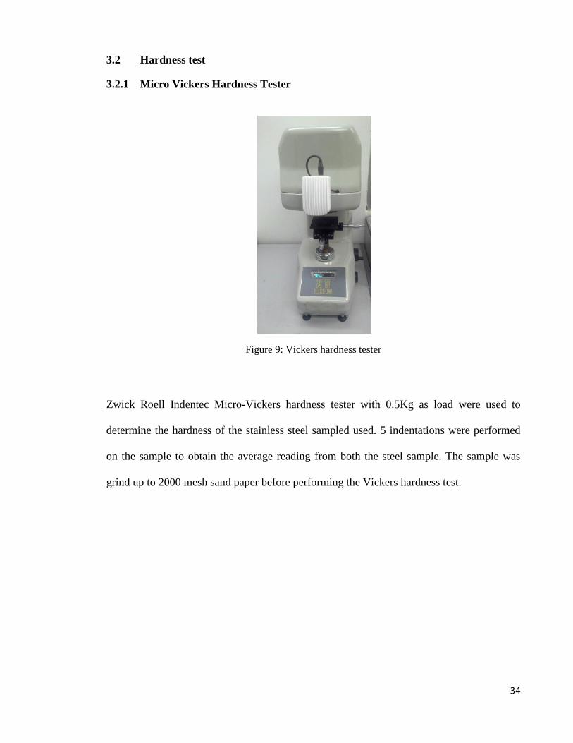
Figure 9: Vickers hardness tester
Zwick Roell Indentec Micro-Vickers hardness tester with 0.5Kg as load were used to
determine the hardness of the stainless steel sampled used. 5 indentations were performed
on the sample to obtain the average reading from both the steel sample. The sample was
grind up to 2000 mesh sand paper before performing the Vickers hardness test.
35
3.3 Metallography
Stainless steel 316L and 304 samples, that were grounded up to 2000 mesh was
later polish with 1µm diamond paste. The sample was later clean via acetone and etched
with Kalling-2 etchant. The microstructure was observed via optical microscope.
3.4 Electrochemical Test
3.4.1 Potentiodynamic Polarisation Test
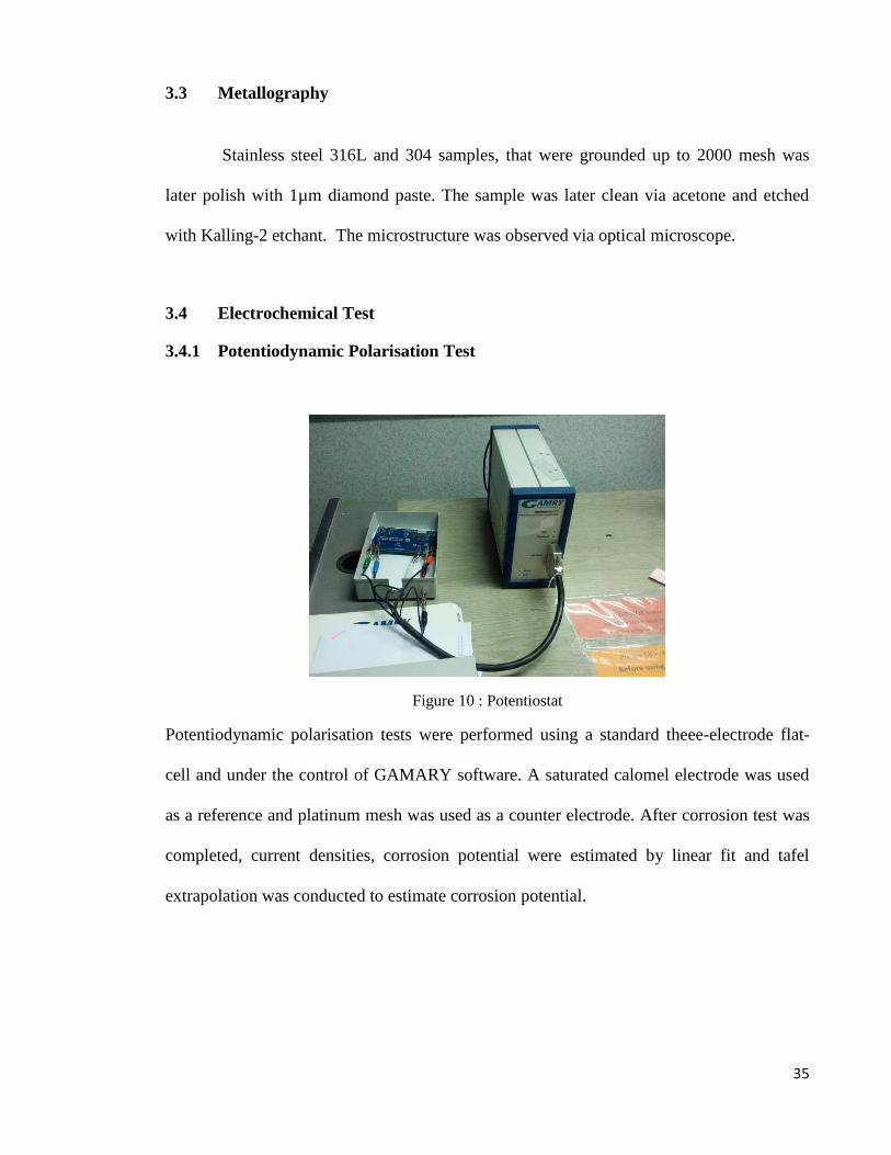
Figure 10 : Potentiostat
Potentiodynamic polarisation tests were performed using a standard theee-electrode flat-
cell and under the control of GAMARY software. A saturated calomel electrode was used
as a reference and platinum mesh was used as a counter electrode. After corrosion test was
completed, current densities, corrosion potential were estimated by linear fit and tafel
extrapolation was conducted to estimate corrosion potential.
36
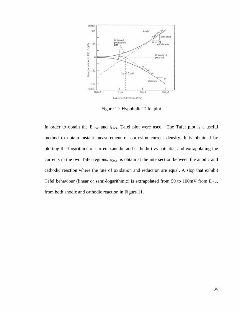
Figure 11: Hypobolic Tafel plot
In order to obtain the ECoor and iCoor, Tafel plot were used. The Tafel plot is a useful
method to obtain instant measurement of corrosion current density. It is obtained by
plotting the logarithms of current (anodic and cathodic) vs potential and extrapolating the
currents in the two Tafel regions. iCoor is obtain at the intersection between the anodic and
cathodic reaction where the rate of oxidation and reduction are equal. A slop that exhibit
Tafel behaviour (linear or semi-logarithmic) is extrapolated from 50 to 100mV from ECoor
from both anodic and cathodic reaction in Figure 11.
37
Figure 12 : Apparatus set up
Potentiodynamic polarisation (PDP) test were perform using the set up above. The
electrolyte used in the test was 3.5%NaCl. The scan rate of the experiment was selected at
1mV/second of potentiodynamic polarisation test. The initial and the end voltage are
inserted into the software before conducting the polarisation test. Once the test is complete
the sample is removed and store in an air tight container for SEM testing. First the test is
conducted using the first sample of stainless steel 316L and then repeated using the second
sample of 316L and followed by 304.
38
3.5 Surface Characterisation
3.5.1 SEM and EDX
Figure 13: PHENOM Table Top SEM
PHENOM ProX table top SEM with built in EDX features at Faculty of
Engineering UM was used to identify and observe the severity of the pitting. The images
were observed using back scattered electron (BSE) and the elements in the pits were
analysed via energy-dispersive X-ray (EDX). Stainless steel test sample after
electrochemical testing were analysed using the SEM and EDX above.
The polish sample of both stainless steel 316L and 304 were analysed via SEM to
determinate the surface condition as for reference purposes. The stainless steel sample that
underwent the electrochemical test, were then analyzed in SEM and EDX. The same
magnifications were chosen to differentiate the intensity of pitting between both stainless
316L and 304. Several pitting spot were analysed via EDX to identify its principle
elemental constituent.

39
The test data and the experimental result that were obtained was complied and
analysed according to determine the effect of cathodic current density on the criticality of
pitting using potentiodynamic test and SEM.
40
CHAPTER 4 RESULT AND DISCUSSION
4.1 Hardness
Table 4 : Average hardness measurement of stainless steel 316L and 304
Material/ Hardness
reading 316L stainless steel 304 stainless steel
1st 161HV 235HV
2nd
178HV 275HV
3rd
181HV 256HV
4th 180HV 239HV
5th 178HV 248HV
Average Vickers
hardness 175HV 251HV
Stainless steel 316L has a lower hardness with respect to stainless steel 304 in Table
4. This is because stainless steel 304 has a higher carbon content that stainless steel 316L.
The Vickers hardness of 316L and 304 stainless steel are in agreement with the hardness
value reported by (Muthukumaran, Selladurai, Nandhakumar, & Senthilkumar, 2010)and
(Milad, Zreiba, Elhalouani, & Baradai, 2008).
41
4.2 Metallography
4.2.1 Microstructure of Stainless steel 316L
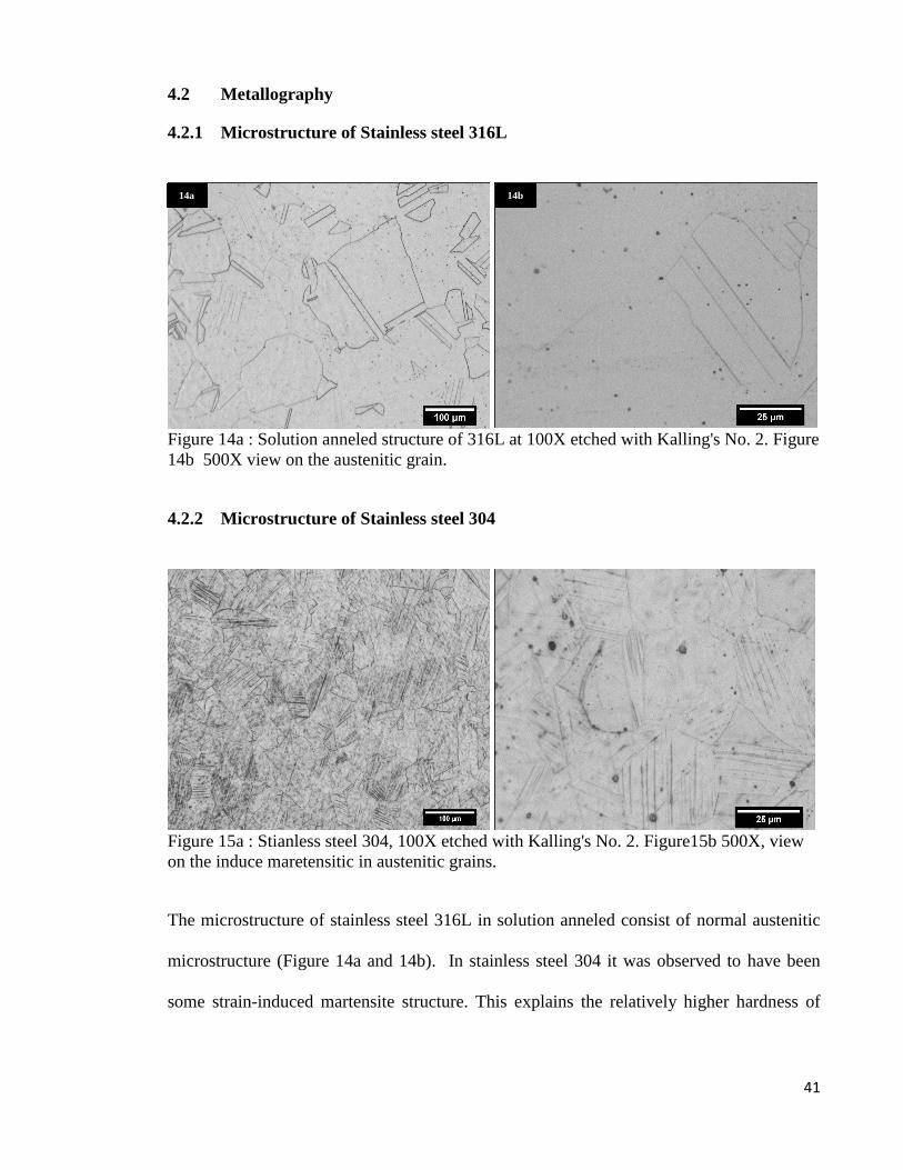
Figure 14a : Solution anneled structure of 316L at 100X etched with Kalling's No. 2. Figure
14b 500X view on the austenitic grain.
4.2.2 Microstructure of Stainless steel 304
Figure 15a : Stianless steel 304, 100X etched with Kalling's No. 2. Figure15b 500X, view
on the induce maretensitic in austenitic grains.
The microstructure of stainless steel 316L in solution anneled consist of normal austenitic
microstructure (Figure 14a and 14b). In stainless steel 304 it was observed to have been
some strain-induced martensite structure. This explains the relatively higher hardness of
14a 14b
42
304 relative to 316L recorded in Table 4. There must have been some amount of cold work
involved in stainless steel 304 that has caused induced mastensite structure.
4.3 Electrochemical test
Figure 16 : Polarisation curve of stainless steel 316L and 304.
Figure 16 display the result of the potentiodynamic test for both stainless steel 316L
and 304 in a graph. From the Figure 16, it is very much visible that stainless steel 316L has
a higher corrosion potential ECoor than stainless steel 304.
-700.00
-600.00
-500.00
-400.00
-300.00
-200.00
-100.00
0.00
100.00
200.00
0.00001 0.00010 0.00100 0.01000 0.10000 1.00000 10.00000
Ap
plie
d p
ote
nti
al (
mV
)
Log Values of current density(mA/cm2 )
Polarisation curve of stainless steel 316L & 304
316L
304
ECorr 316L
ECorr 304
43
4.4 Tafel plots analysis
Figure 17 : Tafel plot for stainless steel 304
Figure 18 : Tafel plot for stainless steel 316L
-700.00
-600.00
-500.00
-400.00
-300.00
-200.00
-100.00
0.00
100.00
200.00
-4.50000 -3.50000 -2.50000 -1.50000 -0.50000 0.50000
Ap
plie
d p
ote
nti
al (
mV
)
Log Values of current density(mA/cm2 )
Stainless steel 304
-700.00
-600.00
-500.00
-400.00
-300.00
-200.00
-100.00
0.00
100.00
200.00
-5.00000 -4.00000 -3.00000 -2.00000 -1.00000 0.00000 1.00000
Ap
plie
d p
ote
nti
al (
mV
)
Log Values of current density(mA/cm2 )
Stainless steel 316L
316L
ECorr 304= -160mV
iCorr 304= 1.6mA/cm2
ECorr 316L= -100mV
ECorr 316L= -2.0mA/cm2
44
Table 5 : Electrochemical result
Material ECorr Corrosion
potential/mV
ICorr Corrosion current
density/(mA/cm2)
304 -160 1.6
316L -100 2.0
Figure 17 and Figure 18, is the extropoltion of the tafel method to obtain the ECorr
and ICorr value. The Potentiodynamic of both stainless steel 316L and 304 conducted at
25˚C in 3.5% NaCl electrolyte and scanning rate of 1mV/s. The result in table 5 indicates
that 316L has a higher ECorr with reference to 304, since the inflection point of 316L are
above 304. The higher ECorr of 316L may be explained by the higher chromium and nickel
compared to 304. In general higher chromium and nickel improve the corrosion resistance
of stainless steel.
As discussed in the literature review on David G Enos work, on potentiodynamic
polarisation scan, a typical cathodic polarisation curve will consist of two stages, which the
oxygen reduction stage and the hydrogen evolution stages (Enos, 2008). Form the result in
figure 16, it is observed the electrode potential for hydrogen embrittlement has not been
achieved, thus the dominant reaction is the reduction of oxygen. Base on the microstrcutre
of stainless steel 304, it was identified to have small amount of strain induce martensite.
Having martensite in the microstructure would very much lower down the corrosion
potential as it have reported by Alvarez (Alvarez et al., 2013).
45
Figure 19 : Cathodic graph and tafel extrapolation
The cathodic graph in Figure 19 shows that stainless steel 304 has a faster and a lower
cathodic reaction rate compared to 316L. This explains the finding in SEM (Figure 23a and
23b), where there were more pitting corrosion observed in 304 compared to stainless steel
316L.
-700.00
-600.00
-500.00
-400.00
-300.00
-200.00
-100.00
0.00
0.00100 0.01000 0.10000 1.00000
Ap
plie
d p
ote
nti
al (
mV
)
Log Values of current density(mA/cm2 )
Cathodic graph
316L cathodic
304 cathodic
46
4.5 SEM
4.5.1 Stainless steel 304 and 316L polish surface
Figure 20a : Stainless steel 304 at 400X, Figure 20b: stainless steel 316L at 400X
Figure 21a : Stainless steel 304 at 2700X, Figure 21b: stainless steel 316L at 2700X
20a 20b
21b 21a
47
Figure 22a : Stainless steel 304 at 9100X, Figure 22b: stainless steel 316L at 9100X
A polish 304 was analysed using SEM, the result in Figure 21 and Figure 22 indicate
several formation of pits in different magnification. This pits are not a result of corrosion,
however are result of the polishing and the polishing method. Both the sample were polish
up to 3µ and then up to 1µm with diamond paste. The polishing was done in an automated
polish machine that polishes at high rpm. Usually soft materials are polish with low rmp
and with low pressure. If pits are still present, its recommended to polish for short periods
and to clean it between.
22b 22a
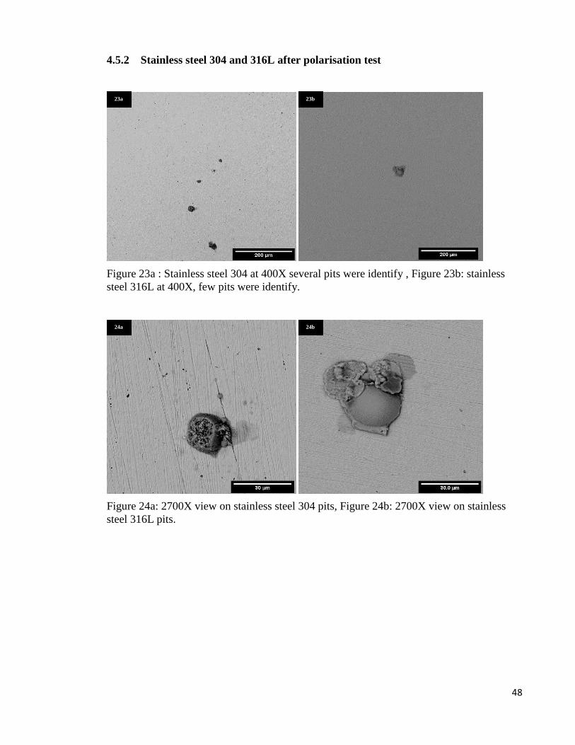
48
4.5.2 Stainless steel 304 and 316L after polarisation test
Figure 23a : Stainless steel 304 at 400X several pits were identify , Figure 23b: stainless
steel 316L at 400X, few pits were identify.
Figure 24a: 2700X view on stainless steel 304 pits, Figure 24b: 2700X view on stainless
steel 316L pits.
23a
24a
23b
24b
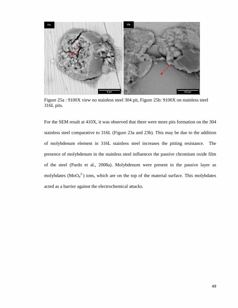
49
Figure 25a : 9100X view no stainless steel 304 pit, Figure 25b: 9100X on stainless steel
316L pits.
For the SEM result at 410X, it was observed that there were more pits formation on the 304
stainless steel comparative to 316L (Figure 23a and 23b). This may be due to the addition
of molybdenum element in 316L stainless steel increases the pitting resistance. The
presence of molybdenum in the stainless steel influences the passive chromium oxide film
of the steel (Pardo et al., 2008a). Molybdenum were present in the passive layer as
molybdates (MoO42-
) ions, which are on the top of the material surface. This molybdates
acted as a barrier against the electrochemical attacks.
25a 25b
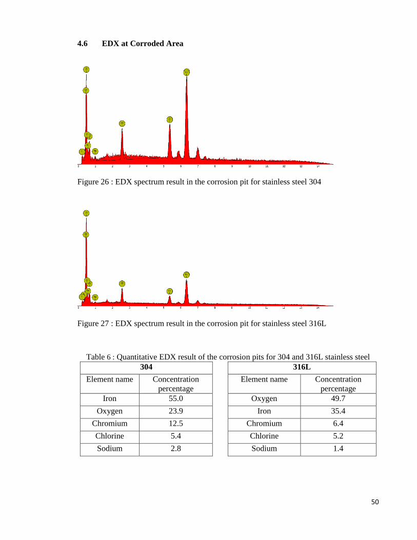
50
4.6 EDX at Corroded Area
Figure 26 : EDX spectrum result in the corrosion pit for stainless steel 304
Figure 27 : EDX spectrum result in the corrosion pit for stainless steel 316L
Table 6 : Quantitative EDX result of the corrosion pits for 304 and 316L stainless steel
304 316L
Element name Concentration
percentage
Element name Concentration
percentage
Iron 55.0 Oxygen 49.7
Oxygen 23.9 Iron 35.4
Chromium 12.5 Chromium 6.4
Chlorine 5.4 Chlorine 5.2
Sodium 2.8 Sodium 1.4
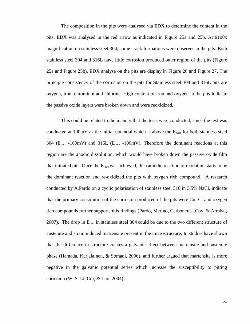
51
The composition in the pits were analysed via EDX to determine the content in the
pits. EDX was analysed in the red arrow as indicated in Figure 25a and 25b. At 9100x
magnification on stainless steel 304, some crack formations were observer in the pits. Both
stainless steel 304 and 316L have little corrosion produced outer region of the pits (Figure
25a and Figure 25b). EDX analyse on the pits are display in Figure 26 and Figure 27. The
principle consistency of the corrosion on the pits for Stainless steel 304 and 316L pits are
oxygen, iron, chromium and chlorine. High content of iron and oxygen in the pits indicate
the passive oxide layers were broken down and were reoxidized.
This could be related to the manner that the tests were conducted, since the test was
conducted at 100mV as the initial potential which is above the Ecorr for both stainless steel
304 (Ecorr -160mV) and 316L (Ecorr -100mV). Therefore the dominant reactions at this
region are the anodic dissolution, which would have broken down the passive oxide film
that initiated pits. Once the Ecorr was achieved, the cathodic reaction of oxidation starts to be
the dominant reaction and re-oxidized the pits with oxygen rich compound. A research
conducted by A.Pardo on a cyclic polarisation of stainless steel 316 in 3.5% NaCl, indicate
that the primary constitution of the corrosion produced of the pits were Cu, Cl and oxygen
rich compounds further supports this findings (Pardo, Merino, Carboneras, Coy, & Arrabal,
2007). The drop in Ecorr in stainless steel 304 could be due to the two different structure of
austenite and strain induced martensite present in the microstructure. In studies have shown
that the difference in structure creates a galvanic effect between martensite and austenite
phase (Hamada, Karjalainen, & Somani, 2006), and further argued that martensite is more
negative in the galvanic potential series which increase the susceptibility to pitting
corrosion (W. S. Li, Cui, & Luo, 2004).
52
CHAPTER 5 CONCLUSION
This project paper seeks to understand the natural behaviour of stainless steel in impress
current cathodic protection and its effect of cathodic current on it. In order to understand its
behaviours, various test were conducted. One of the test is a potentiodynamic test was
conducted in a 3.5% NaCl electrolyte in a 1mV/s scanning rate in a potentiostat in order to
obtain the polarisation curve.
Various information was extracted from the polarisation curve, such as the corrosion
potential and the corrosion current density. The same sample that was used for
potentiodynamic testing was than analysed in SEM and EDX.
A few major conclusions have been made with the limited context of the project paper and
it is summarised as the following:
The cathodic polarisation curve of stainless steel 316L and 304 3.5% NaCl were
successfully obtained and analysed. The result indicate that the 304 stainless steel
(ECorr= -160mV) has a higher corrosion potential compared to 316L (ECorr= -
100mV). And this is attributed to the alloying element of 316L stainless steel, which
has higher levels of chromium, nickel and molybdenum content. The cathodic
reaction of 304stainless steel occurs in a faster rate, with respect to 316L. These
reactions are suspected to be dominated pit the pits formation 304 stainless steel.
The (icorr) corrosion current density for 304 is 1.6mA/cm2 and of stainless steel
316L is 2.0mA/cm2.
The SEM and EDX result reveals that pitting corrosion were more predominant in
stainless steel 304 with respect to 316L. This may be due to a combination of
factors such as, stress induced martensite structure in stainless steel 304, alloying

53
elements, and level of inclusion. The EDX analysis of the pits reveals that the
principle constituents are oxygen, iron, chromium, and chlorine. This is an
indication of the early stages of pits formation and followed by the cathodic reaction
(oxygen reduction).
54
REFERENCE
Ahmad, Z. (2006). Principles of Corrosion Engineering and Corrosion Control,
Alvarez, S. M., Bautista, A., & Velasco, F. (2013). Influence of strain-induced martensite
in the anodic dissolution of austenitic stainless steels in acid medium. Corrosion
Science, 69, 130-138. doi: 10.1016/j.corsci.2012.11.033
ASM. (2000). Introduction to Stainless SteelsAlloy Digest Sourcebook: Stainless Steels
(#06940G).
Balasubramaniam, R. (2010). CALLISTER'S MATERIALS SCIENCE AND ENGINEERING
(With CD ): Wiley India Pvt. Limited.
Barbalat, M., Caron, D., Lanarde, L., Meyer, M., Fontaine, S., Castillon, F., . . . Refait, P.
(2013). Estimation of residual corrosion rates of steel under cathodic protection in
soils via voltammetry. Corrosion Science, 73, 222-229. doi:
10.1016/j.corsci.2013.03.038
Cai, B., Liu, Y., Tian, X., Wang, F., Li, H., & Ji, R. (2010). An experimental study of
crevice corrosion behaviour of 316L stainless steel in artificial seawater. Corrosion
Science, 52(10), 3235-3242. doi: 10.1016/j.corsci.2010.05.040
Chen, X., Li, X. G., Du, C. W., & Cheng, Y. F. (2009). Effect of cathodic protection on
corrosion of pipeline steel under disbonded coating. Corrosion Science, 51(9),
2242-2245. doi: 10.1016/j.corsci.2009.05.027
Cheng, Y. F., & Niu, L. (2007). Mechanism for hydrogen evolution reaction on pipeline
steel in near-neutral pH solution. Electrochemistry Communications, 9(4), 558-562.
doi: 10.1016/j.elecom.2006.10.035
Crundwell, R. F. (2010). Sacrificial Anodes. In B. C. G. L. L. R. S. Stott (Ed.), Shreir's
Corrosion (pp. 2763-2780). Oxford: Elsevier.
Dong, C. F., Fu, A. Q., Li, X. G., & Cheng, Y. F. (2008). Localized EIS characterization of
corrosion of steel at coating defect under cathodic protection. Electrochimica Acta,
54(2), 628-633. doi: 10.1016/j.electacta.2008.07.016
55
Du, C. W., Li, X. G., Chen, X., Liang, P., & Guo, H. (2008). Crevice corrosion behavior of
X70 steel in HCO−3 solution under cathodic polarization. Acta Metallurgica Sinica
(English Letters), 21(4), 235-244. doi: http://dx.doi.org/10.1016/S1006-
7191(08)60044-7
Enos, D. G. (2008). The Potentiodynamic Polarization Scan (Vol. Tehnical Report 33):
Center for Electrochemical Science & Engineering, Department of Materials
Science & Engineering, University of Virginia, Charlottesville, VA.
Eslami, A., Kania, R., Worthingham, B., Boven, G. V., Eadie, R., & Chen, W. (2011).
Effect of CO2 and R-ratio on near-neutral pH stress corrosion cracking initiation
under a disbonded coating of pipeline steel. Corrosion Science, 53(6), 2318-2327.
doi: 10.1016/j.corsci.2011.03.017
Fontana, M. G. (1986). Corrosion Engineering: McGraw-Hill.
Freire, L., Carmezim, M. J., Ferreira, M. G. S., & Montemor, M. F. (2011). The
electrochemical behaviour of stainless steel AISI 304 in alkaline solutions with
different pH in the presence of chlorides. Electrochimica Acta, 56(14), 5280-5289.
doi: 10.1016/j.electacta.2011.02.094
Genel, K., Demirkol, M., & Ürgen, M. (2002). Effect of cathodic polarisation on corrosion
fatigue behaviour of ion nitrided AISI 4140 steel. International Journal of Fatigue,
24(5), 537-543. doi: http://dx.doi.org/10.1016/S0142-1123(01)00114-1
Gurrappa, I. (2005). Cathodic protection of cooling water systems and selection of
appropriate materials. Journal of Materials Processing Technology, 166(2), 256-
267. doi: 10.1016/j.jmatprotec.2004.09.074
Hack, H. P. (1999). Designing Cathodic Protection Systems for Marine Structures and
Vehicles: ASTM.
Hamada, A. S., Karjalainen, L. P., & Somani, M. C. (2006). Electrochemical corrosion
behaviour of a novel submicron-grained austenitic stainless steel in an acidic NaCl
solution. Materials Science and Engineering: A, 431(1-2), 211-217. doi:
10.1016/j.msea.2006.05.138
Hermas, A. A., & Morad, M. S. (2008). A comparative study on the corrosion behaviour of
304 austenitic stainless steel in sulfamic and sulfuric acid solutions. Corrosion
Science, 50(9), 2710-2717. doi: 10.1016/j.corsci.2008.06.029

56
Huneau, B., & Mendez, J. (2003). Fatigue behavior of a high strength steel in vacuum, in
air and in 3.5% NaCl solution under cathodic protection. Materials Science and
Engineering: A, 345(1–2), 14-22. doi: http://dx.doi.org/10.1016/S0921-
5093(02)00099-0
Huneau, B., & Mendez, J. (2006). Evaluation of environmental effects on fatigue crack
growth behaviour of a high strength steel in a saline solution with cathodic
protection. International Journal of Fatigue, 28(2), 124-131. doi:
http://dx.doi.org/10.1016/j.ijfatigue.2005.04.011
Jang, S.-K., Han, M.-S., & Kim, S.-J. (2009). Electrochemical characteristics of stainless
steel using impressed current cathodic protection in seawater. Transactions of
Nonferrous Metals Society of China, 19(4), 930-934. doi: 10.1016/s1003-
6326(08)60380-5
Javidi, M., & Bahalaou Horeh, S. (2014). Investigating the mechanism of stress corrosion
cracking in near-neutral and high pH environments for API 5L X52 steel. Corrosion
Science, 80, 213-220. doi: 10.1016/j.corsci.2013.11.031
Jin, G. X., Xie, Y. P., & Tian, A. H. (2012). Corrosion failure analysis of the condensate
collector vessel head of evaporation system in ethylene glycol device. Engineering
Failure Analysis, 22, 113-120. doi: 10.1016/j.engfailanal.2012.01.017
Kim, S.-J., Okido, M., & Moon, K.-M. (2003). An electrochemical study of cathodic
protection of steel used for marine structures. Korean Journal of Chemical
Engineering, 20(3), 560-565. doi: 10.1007/BF02705566
Lei, C., Liu, Y., Zhou, H., Feng, Z., & Du, R. (2013). Photogenerated cathodic protection
of stainless steel by liquid-phase-deposited sodium polyacrylate/TiO2 hybrid films.
Corrosion Science, 68, 214-222. doi: 10.1016/j.corsci.2012.11.019
Li, D. G., Wang, J. D., Chen, D. R., & Liang, P. (2014). Influences of pH value,
temperature, chloride ions and sulfide ions on the corrosion behaviors of 316L
stainless steel in the simulated cathodic environment of proton exchange membrane
fuel cell. Journal of Power Sources, 272, 448-456. doi:
10.1016/j.jpowsour.2014.06.121
Li, M. C., & Cheng, Y. F. (2008). Corrosion of the stressed pipe steel in carbonate–
bicarbonate solution studied by scanning localized electrochemical impedance
spectroscopy. Electrochimica Acta, 53(6), 2831-2836. doi:
10.1016/j.electacta.2007.10.077
57
Li, W. S., Cui, N., & Luo, J. L. (2004). Pitting initiation and propagation of hypoeutectoid
iron-based alloy with inclusions of martensite in chloride-containing nitrite
solutions. Electrochimica Acta, 49(9-10), 1663-1672. doi: 10.1016/s0013-
4686(03)01014-4
Lindley, C., & Rudd, W. J. (2001). Influence of the level of cathodic protection on the
corrosion fatigue properties of high-strength welded joints. Marine Structures,
14(4–5), 397-416. doi: http://dx.doi.org/10.1016/S0951-8339(00)00048-4
Liu, Z. Y., Li, X. G., & Cheng, Y. F. (2011). Electrochemical state conversion model for
occurrence of pitting corrosion on a cathodically polarized carbon steel in a near-
neutral pH solution. Electrochimica Acta, 56(11), 4167-4175. doi:
10.1016/j.electacta.2011.01.100
Liu, Z. Y., Li, X. G., & Cheng, Y. F. (2012a). Mechanistic aspect of near-neutral pH stress
corrosion cracking of pipelines under cathodic polarization. Corrosion Science, 55,
54-60. doi: 10.1016/j.corsci.2011.10.002
Liu, Z. Y., Li, X. G., & Cheng, Y. F. (2012b). Understand the occurrence of pitting
corrosion of pipeline carbon steel under cathodic polarization. Electrochimica Acta,
60, 259-263. doi: 10.1016/j.electacta.2011.11.051
Loto, R. T. (2013). Pitting corrosion evaluation of austenitic stainless steel type 304 in acid
chloride media. J. Mater. Environ. Sci. 4 (4) (2013) 448-459, Department of
Chemical and Metallurgical Engineering, Tshwane University of Technology,
Pretoria, South Africa.
Matula, M., Hyspecka, L., Svoboda, M., Vodarek, V., Dagbert, C., Galland, J., . . . Tuma,
L. (2001). Intergranular corrosion of AISI 316L steel. Materials Characterization,
46(2–3), 203-210. doi: http://dx.doi.org/10.1016/S1044-5803(01)00125-5
Metwally, I. A., Al-Mandhari, H. M., Gastli, A., & Nadir, Z. (2007). Factors affecting
cathodic-protection interference. Engineering Analysis with Boundary Elements,
31(6), 485-493. doi: 10.1016/j.enganabound.2006.11.003
Milad, M., Zreiba, N., Elhalouani, F., & Baradai, C. (2008). The effect of cold work on
structure and properties of AISI 304 stainless steel. Journal of Materials Processing
Technology, 203(1-3), 80-85. doi: 10.1016/j.jmatprotec.2007.09.080
Mustapha, A., Charles, E. A., & Hardie, D. (2012). Evaluation of environment-assisted
cracking susceptibility of a grade X100 pipeline steel. Corrosion Science, 54, 5-9.
doi: 10.1016/j.corsci.2011.08.030
58
Muthukumaran, V., Selladurai, V., Nandhakumar, S., & Senthilkumar, M. (2010).
Experimental investigation on corrosion and hardness of ion implanted AISI 316L
stainless steel. Materials & Design, 31(6), 2813-2817. doi:
10.1016/j.matdes.2010.01.007
Oni, A. (1996). Effects of cathodic overprotection on some mechanical properties of a dual-
phase low-alloy steel in sea water. Construction and Building Materials, 10(6), 481-
484. doi: http://dx.doi.org/10.1016/0950-0618(95)00086-0
Pardo, A., Merino, M. C., Carboneras, M., Coy, A. E., & Arrabal, R. (2007). Pitting
corrosion behaviour of austenitic stainless steels with Cu and Sn additions.
Corrosion Science, 49(2), 510-525. doi: 10.1016/j.corsci.2006.06.004
Pardo, A., Merino, M. C., Coy, A. E., Viejo, F., Arrabal, R., & Matykina, E. (2008a).
Effect of Mo and Mn additions on the corrosion behaviour of AISI 304 and 316
stainless steels in H2SO4. Corrosion Science, 50(3), 780-794. doi:
10.1016/j.corsci.2007.11.004
Pardo, A., Merino, M. C., Coy, A. E., Viejo, F., Arrabal, R., & Matykina, E. (2008b).
Pitting corrosion behaviour of austenitic stainless steels – combining effects of Mn
and Mo additions. Corrosion Science, 50(6), 1796-1806. doi:
10.1016/j.corsci.2008.04.005
Park, H., Kim, K. Y., & Choi, W. (2001). A novel photoelectrochemical method of metal
corrosion prevention using a TiO2 solar panel. Chemical Communications(3), 281-
282.
Park, H., Kim, K. Y., & Choi, W. (2002). Photoelectrochemical approach for metal
corrosion prevention using a semiconductor photoanode. Journal of Physical
Chemistry B, 106(18), 4775-4781. doi: 10.1021/jp025519r
Perdomo, J. J., & Song, I. (2000). Chemical and electrochemical conditions on steel under
disbonded coatings: the effect of applied potential, solution resistivity, crevice
thickness and holiday size. Corrosion Science, 42(8), 1389-1415. doi:
http://dx.doi.org/10.1016/S0010-938X(99)00136-5
Roberge, P. (1999). Handbook of Corrosion Engineering: Mcgraw-hill.
Roberge, P. R. (2000). Handbook of Corrosion Engineering. 11. Cathodic protection.
59
Roffey, P., & Davies, E. H. (2014). The generation of corrosion under insulation and stress
corrosion cracking due to sulphide stress cracking in an austenitic stainless steel
hydrocarbon gas pipeline. Engineering Failure Analysis, 44, 148-157. doi:
10.1016/j.engfailanal.2014.05.004
Shipilov, S. A., & Le May, I. (2006). Structural integrity of aging buried pipelines having
cathodic protection. Engineering Failure Analysis, 13(7), 1159-1176. doi:
10.1016/j.engfailanal.2005.07.008
Smith, W. F. (1993). Structure and Properties of Engineering Alloys: McGraw-Hill.
Solheim, K. G., & Solberg, J. K. (2013). Hydrogen induced stress cracking in
supermartensitic stainless steels – Stress threshold for coarse grained HAZ.
Engineering Failure Analysis, 32, 348-359. doi: 10.1016/j.engfailanal.2013.04.003
Song, F. M., & Sridhar, N. (2008). Modeling pipeline crevice corrosion under a disbonded
coating with or without cathodic protection under transient and steady state
conditions. Corrosion Science, 50(1), 70-83. doi: 10.1016/j.corsci.2007.05.024
Wang, W., Wang, Q., Wang, C., & Yi, J. (2014). Experimental studies of crevice corrosion
for buried pipeline with disbonded coatings under cathodic protection. Journal of
Loss Prevention in the Process Industries, 29, 163-169. doi:
10.1016/j.jlp.2014.02.007
William Smith, W. F. (1993). Structure and Properties of Engineering Alloys Second
Edition McGraw-Hill.
Xin, S. S., & Li, M. C. (2014). Electrochemical corrosion characteristics of type 316L
stainless steel in hot concentrated seawater. Corrosion Science, 81, 96-101. doi:
10.1016/j.corsci.2013.12.004
Xu, C., Zhang, Y., Cheng, G., & Zhu, W. (2008). Pitting corrosion behavior of 316L
stainless steel in the media of sulphate-reducing and iron-oxidizing bacteria.
Materials Characterization, 59(3), 245-255. doi: 10.1016/j.matchar.2007.01.001
Xu, L. Y., Su, X., & Cheng, Y. F. (2013). Effect of alternating current on cathodic
protection on pipelines. Corrosion Science, 66(0), 263-268. doi:
http://dx.doi.org/10.1016/j.corsci.2012.09.028
60
Yuan, J., & Tsujikawa, S. (1995). Characterization of sol-gel-derived TiO2 coatings and
their photoeffects on copper substrates. Journal of the Electrochemical Society,
142(10), 3444-3450.
Zakroczymski, T., & Owczarek, E. (2002). Electrochemical investigation of hydrogen
absorption in a duplex stainless steel. Acta Materialia, 50(10), 2701-2713. doi:
http://dx.doi.org/10.1016/S1359-6454(02)00105-2
Zhiyong, L., Zhongyu, C., Xiaogang, L., Cuiwei, D., & Yunying, X. (2014). Mechanistic
aspect of stress corrosion cracking of X80 pipeline steel under non-stable cathodic
polarization. Electrochemistry Communications, 48(0), 127-129. doi:
http://dx.doi.org/10.1016/j.elecom.2014.08.016
Ziaei, S. M. R., Mostowfi, J., Golestani pour, M., & Ziaei, S. A. R. (2013). Failure analysis:
Chloride stress corrosion cracking of AISI 316 stainless steel downhole pressure
memory gauge cover. Engineering Failure Analysis, 33, 465-472. doi:
10.1016/j.engfailanal.2013.06.022
Zucchi, F., Grassi, V., Monticelli, C., & Trabanelli, G. (2006). Hydrogen embrittlement of
duplex stainless steel under cathodic protection in acidic artificial sea water in the
presence of sulphide ions. Corrosion Science, 48(2), 522-530. doi:
10.1016/j.corsci.2005.01.004