Embed Size (px)
Citation preview
USER'S MANUAL* This User's Manual is intended for CJ-70 and CJ-60.
Thank you very much for purchasing the CJ-70/60.
• To ensure correct and safe usage with a full understanding of thisproduct's performance, please be sure to read through this manualcompletely and store it in a safe location.
• Unauthorized copying or transferral, in whole or in part, of thismanual is prohibited.
• The contents of this operation manual and the specifications of thisproduct are subject to change without notice.
• The operation manual and the product have been prepared and testedas much as possible. If you find any misprint or error, please informus.

CJ-70
CJ-60
For the USA
FEDERAL COMMUNICATIONS COMMISSIONRADIO FREQUENCY INTERFERENCE
STATEMENT
This equipment has been tested and found to comply with thelimits for a Class A digital device, pursuant to Part 15 of theFCC Rules.These limits are designed to provide reasonable protectionagainst harmful interference when the equipment is operatedin a commercial environment.This equipment generates, uses, and can radiate radiofrequency energy and, if not installed and used in accordancewith the instruction manual, may cause harmful interferenceto radio communications.Operation of this equipment in a residential area is likely tocause harmful interference in which case the user will berequired to correct the interference at his own expense.
Unauthorized changes or modification to this system can voidthe users authority to operate this equipment.
The I/O cables between this equipment and the computingdevice must be shielded.
NOTICEGrounding Instructions
Do not modify the plug provided - if it will not fit the outlet,have the proper outlet installed by a qualified electrician.
Check with qualified electrician or service personnel if thegrounding instructions are not completely understood, or if indoubt as to whether the tool is properly grounded.
Use only 3-wire extension cords that have 3-pronggrounding plugs and 3-pole receptacles that accept the tool’splug.
Repair or replace damaged or worn out cord immediately.
Operating Instructions
KEEP WORK AREA CLEAN. Cluttered areas and benchesinvites accidents.
DON’T USE IN DANGEROUS ENVIRONMENT. Don’tuse power tools in damp or wet locations, or expose them torain. Keep work area well lighted.
DISCONNECT TOOLS before servicing; when changingaccessories, such as blades, bits, cutters, and like.
REDUCE THE RISK OF UNINTENTIONAL STARTING.Make sure the switch is in off position before plugging in.
USE RECOMMENDED ACCESSORIES. Consult theowner’s manual for recommended accessories. The use ofimproper accessories may cause risk of injury to persons.
NEVER LEAVE TOOL RUNNING UNATTENDED.TURN POWER OFF. Don’t leave tool until it comes to acomplete stop.
For Canada
CLASS A NOTICE
This Class A digital apparatus meets all requirements of theCanadian Interference-Causing Equipment Regulations.
CLASSE A AVIS
Cet appareil numérique de la classe A respecte toutes lesexigences du Règlement sur le matériel brouilleur duCanada.
ROLAND DG CORPORATION1-6-4 Shinmiyakoda, Hamamatsu-shi, Shizuoka-ken, JAPAN 431-2103MODEL NAME : See the MODEL given on the rating plate.RELEVANT DIRECTIVE : EC MACHINERY DIRECTIVE (89/392/EEC)
EC LOW VOLTAGE DIRECTIVE (73/23/EEC)EC ELECTROMAGNETIC COMPATIBILITY DIRECTIVE (89/336/EEC)
ROLAND DG CORPORATION1-6-4 Shinmiyakoda, Hamamatsu-shi, Shizuoka-ken, JAPAN 431-2103MODEL NAME : See the MODEL given on the rating plate.RELEVANT DIRECTIVE : EC MACHINERY DIRECTIVE (89/392/EEC)
EC LOW VOLTAGE DIRECTIVE (73/23/EEC)EC ELECTROMAGNETIC COMPATIBILITY DIRECTIVE (89/336/EEC)
WARNINGThis is a Class A product. In a domestic environment this product may cause radio interference in whichcase the user may be required to take adequate measures.
11
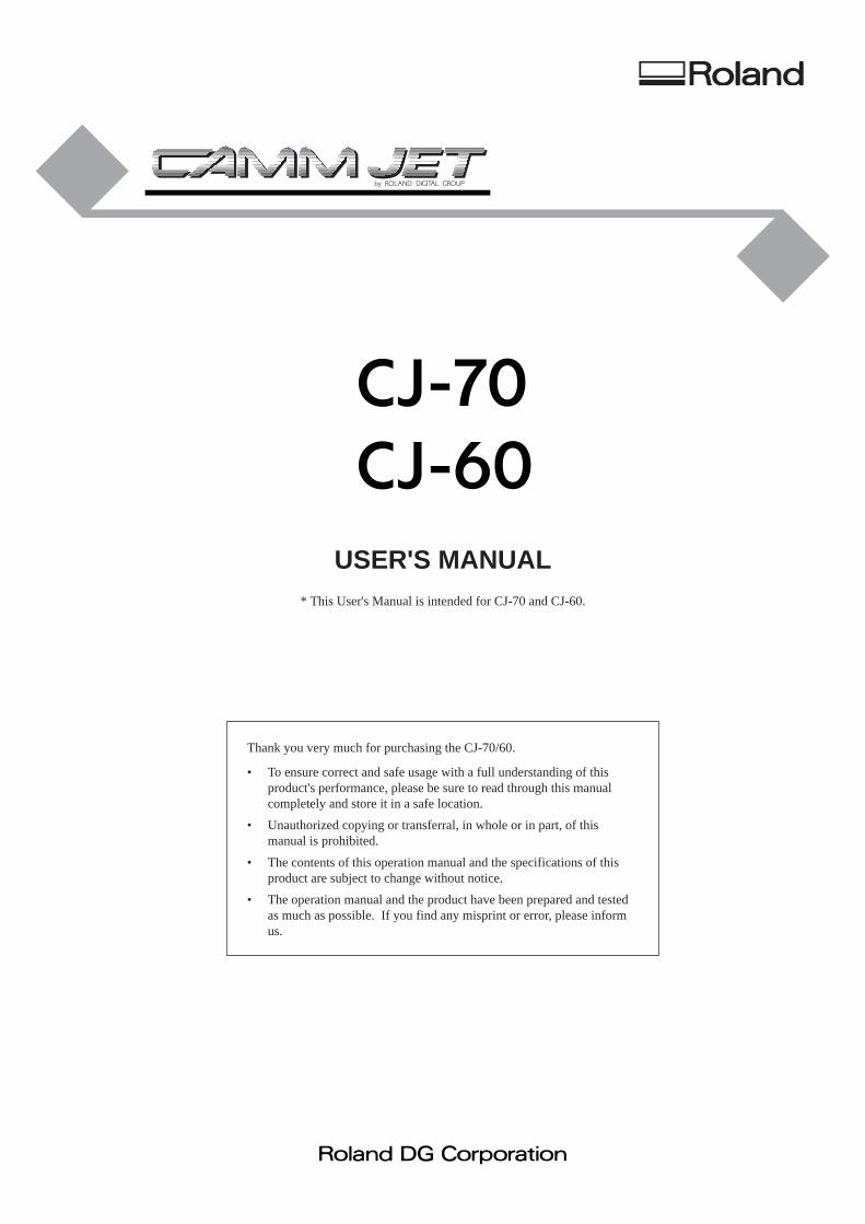
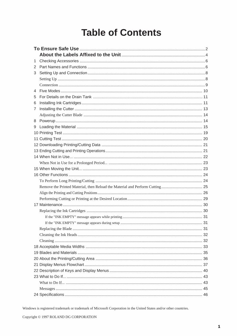
Table of Contents
To Ensure Safe Use ..............................................................................................................................2
About the Labels Affixed to the Unit ....................................................................................4
1 Checking Accessories ..............................................................................................................................6
2 Part Names and Functions ......................................................................................................................6
3 Setting Up and Connection ......................................................................................................................8
Setting Up ....................................................................................................................................................8
Connection ...................................................................................................................................................9
4 Five Modes ..............................................................................................................................................10
5 For Details on the Drain Tank ................................................................................................... 11
6 Installing Ink Cartridges .........................................................................................................................11
7 Installing the Cutter ................................................................................................................................ 13
Adjusting the Cutter Blade .......................................................................................................................14
8 Powerup ...................................................................................................................................................14
9 Loading the Material ..............................................................................................................................15
10 Printing Test ............................................................................................................................................19
11 Cutting Test .............................................................................................................................................20
12 Downloading Printing/Cutting Data .....................................................................................................21
13 Ending Cutting and Printing Operations .................................................................................................21
14 When Not in Use... ................................................................................................................................. 22
When Not in Use for a Prolonged Period... ..............................................................................................23
15 When Moving the Unit... ........................................................................................................................23
16 Other Functions ......................................................................................................................................24
To Perform Long Printing/Cutting ...........................................................................................................24
Remove the Printed Material, then Reload the Material and Perform Cutting.........................................25
Align the Printing and Cutting Positions.........................................................................................................26
Performing Cutting or Printing at the Desired Location........................................................................... 29
17 Maintenance ............................................................................................................................................30
Replacing the Ink Cartridges ....................................................................................................................30
If the "INK EMPTY" message appears while printing................................................................................31
If the "INK EMPTY" message appears during setup..................................................................................31
Replacing the Blade ..................................................................................................................................31
Cleaning the Ink Heads .............................................................................................................................32
Cleaning ....................................................................................................................................................32
18 Acceptable Media Widths .....................................................................................................................33
19 Blades and Materials .............................................................................................................................35
20 About the Printing/Cutting Area ...........................................................................................................36
21 Display Menus Flowchart ......................................................................................................................37
22 Description of Keys and Display Menus .............................................................................................40
23 What to Do If... ........................................................................................................................................43
What to Do If... .........................................................................................................................................43
Messages ...................................................................................................................................................45
24 Specifications ..........................................................................................................................................46
Windows is registered trademark or trademark of Microsoft Corporation in the United States and/or other countries.
Copyright © 1997 ROLAND DG CORPORATION
22
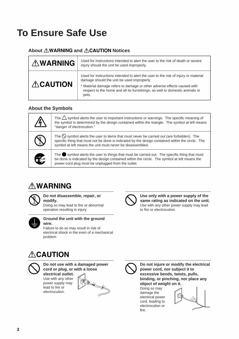
To Ensure Safe Use
Used for instructions intended to alert the user to the risk of death or severeinjury should the unit be used improperly.
About and Notices
Used for instructions intended to alert the user to the risk of injury or materialdamage should the unit be used improperly.
* Material damage refers to damage or other adverse effects caused withrespect to the home and all its furnishings, as well to domestic animals orpets.
About the Symbols
The symbol alerts the user to important instructions or warnings. The specific meaning ofthe symbol is determined by the design contained within the triangle. The symbol at left means"danger of electrocution."
The symbol alerts the user to items that must never be carried out (are forbidden). Thespecific thing that must not be done is indicated by the design contained within the circle. Thesymbol at left means the unit must never be disassembled.
The symbol alerts the user to things that must be carried out. The specific thing that mustbe done is indicated by the design contained within the circle. The symbol at left means thepower-cord plug must be unplugged from the outlet.
Do not disassemble, repair, ormodify.Doing so may lead to fire or abnormaloperation resulting in injury.
Ground the unit with the groundwire.Failure to do so may result in risk ofelectrical shock in the even of a mechanicalproblem
Use only with a power supply of thesame rating as indicated on the unit.Use with any other power supply may leadto fire or electrocution.
Do not use with a damaged powercord or plug, or with a looseelectrical outlet.Use with any otherpower supply maylead to fire orelectrocution.
Do not injure or modify the electricalpower cord, nor subject it toexcessive bends, twists, pulls,binding, or pinching, nor place anyobject of weight on it.Doing so maydamage theelectrical powercord, leading toelectrocution orfire.
33
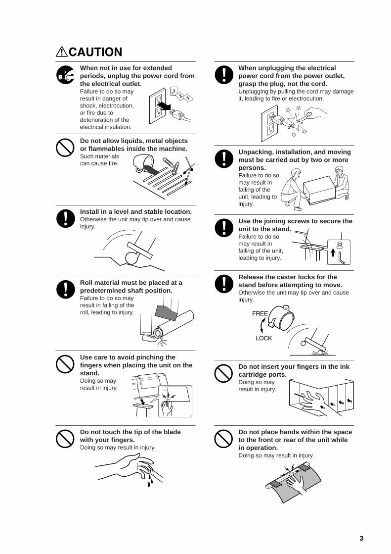
When not in use for extendedperiods, unplug the power cord fromthe electrical outlet.Failure to do so mayresult in danger ofshock, electrocution,or fire due todeterioration of theelectrical insulation.
When unplugging the electricalpower cord from the power outlet,grasp the plug, not the cord.Unplugging by pulling the cord may damageit, leading to fire or electrocution.
Do not allow liquids, metal objectsor flammables inside the machine.Such materialscan cause fire.
Unpacking, installation, and movingmust be carried out by two or morepersons.Failure to do somay result infalling of theunit, leading toinjury.
Install in a level and stable location.Otherwise the unit may tip over and causeinjury.
Use the joining screws to secure theunit to the stand.Failure to do somay result infalling of the unit,leading to injury.
Roll material must be placed at apredetermined shaft position.Failure to do so mayresult in falling of theroll, leading to injury.
Release the caster locks for thestand before attempting to move.Otherwise the unit may tip over and causeinjury.
Use care to avoid pinching thefingers when placing the unit on thestand.Doing so mayresult in injury.
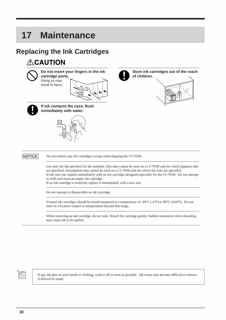
Do not insert your fingers in the inkcartridge ports.Doing so mayresult in injury.
Do not touch the tip of the bladewith your fingers.Doing so may result in injury.
Do not place hands within the spaceto the front or rear of the unit whilein operation.Doing so may result in injury.
44
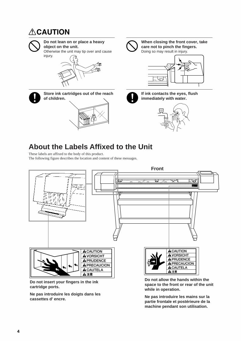
Do not lean on or place a heavyobject on the unit.Otherwise the unit may tip over and causeinjury.
When closing the front cover, takecare not to pinch the fingers.Doing so may result in injury.
Store ink cartridges out of the reachof children.
If ink contacts the eyes, flushimmediately with water.
About the Labels Affixed to the UnitThese labels are affixed to the body of this product.The following figure describes the location and content of these messages.
Front
Do not allow the hands within thespace to the front or rear of the unitwhile in operation.
Ne pas introduire les mains sur lapartie frontale et postérieure de lamachine pendant son utilisation.
Do not insert your fingers in the inkcartridge ports.
Ne pas introduire les doigts dans lescassettes d' encre.
55
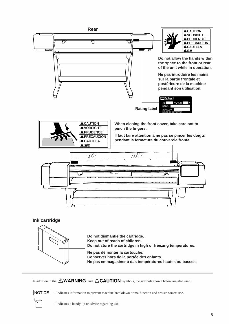
Do not dismantle the cartridge.Keep out of reach of children.Do not store the cartridge in high or freezing temperatures.
Ne pas démonter la cartouche.Conserver hors de la portée des enfants.Ne pas emmagasiner á das températures hautes ou basses.
Ink cartridge
: Indicates information to prevent machine breakdown or malfunction and ensure correct use.
: Indicates a handy tip or advice regarding use.
In addition to the and symbols, the symbols shown below are also used.
When closing the front cover, take care not topinch the fingers.
Il faut faire attention á ne pas se pincer les doigtspendant la fermeture du couvercle frontal.
Rear
Do not allow the hands withinthe space to the front or rearof the unit while in operation.
Ne pas introduire les mainssur la partie frontale etpostérieure de la machinependant son utilisation.
Rating label
6
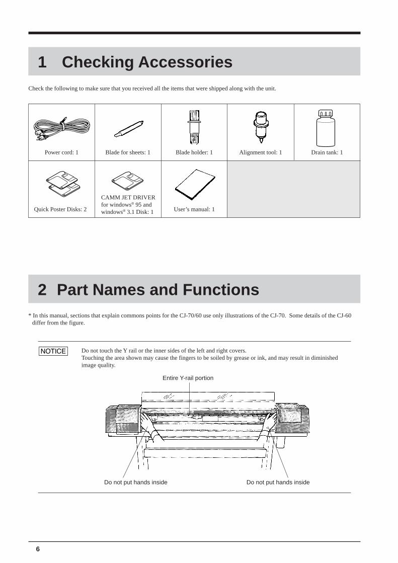
Check the following to make sure that you received all the items that were shipped along with the unit.
1 Checking Accessories
Power cord: 1 Blade for sheets: 1 Blade holder: 1 Alignment tool: 1 Drain tank: 1
User’s manual: 1Quick Poster Disks: 2
CAMM JET DRIVERfor windows® 95 andwindows® 3.1 Disk: 1
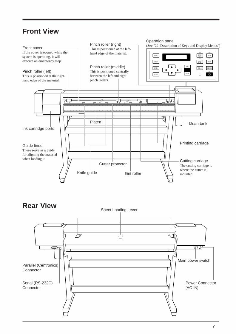
2 Part Names and Functions* In this manual, sections that explain commons points for the CJ-70/60 use only illustrations of the CJ-70. Some details of the CJ-60
differ from the figure.
Do not touch the Y rail or the inner sides of the left and right covers.Touching the area shown may cause the fingers to be soiled by grease or ink, and may result in diminishedimage quality.
Do not put hands insideDo not put hands inside
Entire Y-rail portion
7
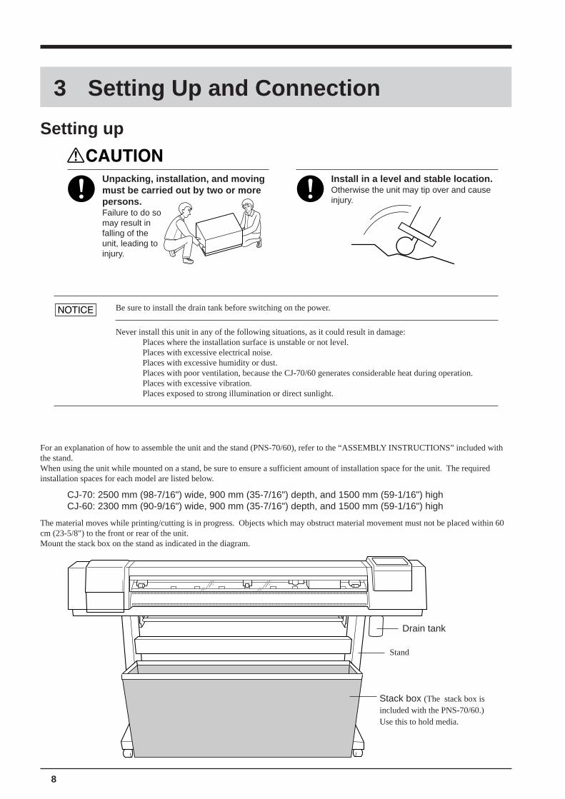
Front View
Serial (RS-232C)Connector
Power Connector[AC IN]
Main power switch
Sheet Loading Lever
Pinch roller (right)This is positioned at the left-hand edge of the material.
Operation panel(See "22 Description of Keys and Display Menus")
Pinch roller (middle)This is positioned centrallybetween the left and rightpinch rollers.
Ink cartridge ports
Platen
Guide linesThese serve as a guidefor aligning the materialwhen loading it. Cutting carriage
The cutting carriage iswhere the cutter ismounted.
Printing carriage
Parallel (Centronics)Connector
Front coverIf the cover is opened while thesystem is operating, it willexecute an emergency stop.
Pinch roller (left)This is positioned at the right-hand edge of the material.
Drain tank
Rear View
Knife guide
Cutter protector
Grit roller
8
3 Setting Up and Connection
Setting up
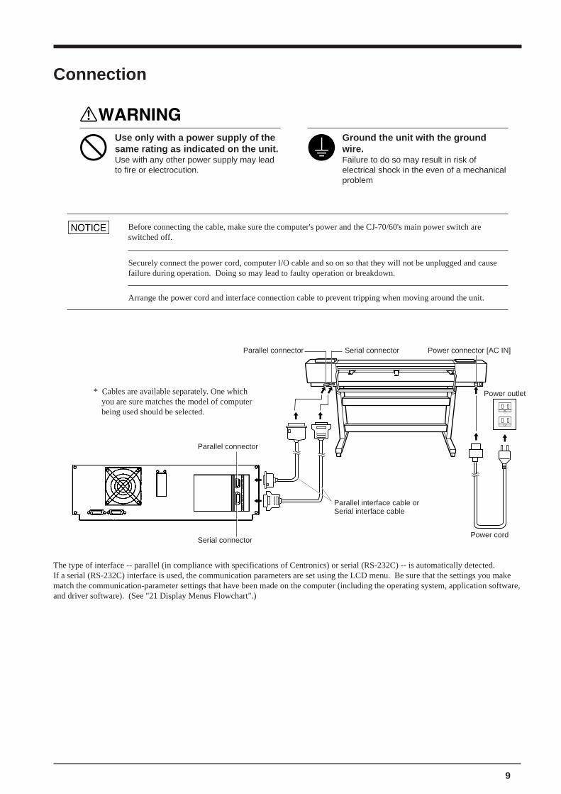
For an explanation of how to assemble the unit and the stand (PNS-70/60), refer to the “ASSEMBLY INSTRUCTIONS” included withthe stand.When using the unit while mounted on a stand, be sure to ensure a sufficient amount of installation space for the unit. The requiredinstallation spaces for each model are listed below.
CJ-70: 2500 mm (98-7/16") wide, 900 mm (35-7/16") depth, and 1500 mm (59-1/16") highCJ-60: 2300 mm (90-9/16") wide, 900 mm (35-7/16") depth, and 1500 mm (59-1/16") high
The material moves while printing/cutting is in progress. Objects which may obstruct material movement must not be placed within 60cm (23-5/8") to the front or rear of the unit.Mount the stack box on the stand as indicated in the diagram.
Stack box (The stack box isincluded with the PNS-70/60.)Use this to hold media.
Stand
Drain tank
Be sure to install the drain tank before switching on the power.
Never install this unit in any of the following situations, as it could result in damage:Places where the installation surface is unstable or not level.Places with excessive electrical noise.Places with excessive humidity or dust.Places with poor ventilation, because the CJ-70/60 generates considerable heat during operation.Places with excessive vibration.Places exposed to strong illumination or direct sunlight.
Unpacking, installation, and movingmust be carried out by two or morepersons.Failure to do somay result infalling of theunit, leading toinjury.
Install in a level and stable location.Otherwise the unit may tip over and causeinjury.
9
The type of interface -- parallel (in compliance with specifications of Centronics) or serial (RS-232C) -- is automatically detected.If a serial (RS-232C) interface is used, the communication parameters are set using the LCD menu. Be sure that the settings you makematch the communication-parameter settings that have been made on the computer (including the operating system, application software,and driver software). (See "21 Display Menus Flowchart".)
Connection
Parallel interface cable orSerial interface cable
Serial connector
Use only with a power supply of thesame rating as indicated on the unit.Use with any other power supply may leadto fire or electrocution.
Ground the unit with the groundwire.Failure to do so may result in risk ofelectrical shock in the even of a mechanicalproblem
Before connecting the cable, make sure the computer's power and the CJ-70/60's main power switch areswitched off.
Securely connect the power cord, computer I/O cable and so on so that they will not be unplugged and causefailure during operation. Doing so may lead to faulty operation or breakdown.
Arrange the power cord and interface connection cable to prevent tripping when moving around the unit.
Parallel connector Power connector [AC IN]
Power outlet
Power cordSerial connector
Parallel connector
* Cables are available separately. One whichyou are sure matches the model of computerbeing used should be selected.
10
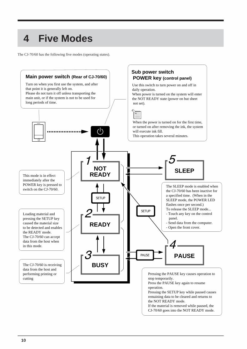
4 Five ModesThe CJ-70/60 has the following five modes (operating states).
Main power switch (Rear of CJ-70/60)
Turn on when you first use the system, and after that point it is generally left on. Please do not turn it off unless transporting the main unit, or if the system is not to be used for long periods of time.
Sub power switch POWER key (control panel)
NOTREADY
READY
BUSY
SLEEP
PAUSE
This mode is in effect immediately after the POWER key is pressed to switch on the CJ-70/60.
Loading material and pressing the SETUP key caused the material size to be detected and enables the READY mode.The CJ-70/60 can accept data from the host when in this mode.
The CJ-70/60 is receiving data from the host and performing printing or cutting
The SLEEP mode is enabled when the CJ-70/60 has been inactive for a specified time. (When in the SLEEP mode, the POWER LED flashes once per second.)To release the SLEEP mode...- Touch any key on the control panel.- Send data from the computer.- Open the front cover.
Pressing the PAUSE key causes operation to stop temporarily.Press the PAUSE key again to resume operation.Pressing the SETUP key while paused causes remaining data to be cleared and returns to the NOT READY mode.If the material is removed while paused, the CJ-70/60 goes into the NOT READY mode.
Use this switch to turn power on and off in daily operation. When power is turned on the system will enterthe NOT READY state (power on but sheet not set).
When the power is turned on for the first time, or turned on after removing the ink, the system will execute ink fill. This operation takes several minutes.
11
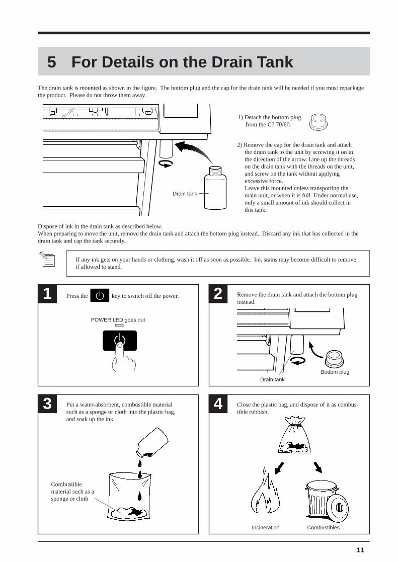
5 For Details on the Drain TankThe drain tank is mounted as shown in the figure. The bottom plug and the cap for the drain tank will be needed if you must repackagethe product. Please do not throw them away.
3 4Put a water-absorbent, combustible materialsuch as a sponge or cloth into the plastic bag,and soak up the ink.
Combustiblematerial such as asponge or cloth
Incineration
Drain tank
1) Detach the bottom plugfrom the CJ-70/60.
2) Remove the cap for the drain tank and attachthe drain tank to the unit by screwing it on inthe direction of the arrow. Line up the threadson the drain tank with the threads on the unit,and screw on the tank without applyingexcessive force.Leave this mounted unless transporting themain unit, or when it is full. Under normal use,only a small amount of ink should collect inthis tank.
1 2Press the key to switch off the power. Remove the drain tank and attach the bottom pluginstead.
POWER LED goes out
If any ink gets on your hands or clothing, wash it off as soon as possible. Ink stains may become difficult to removeif allowed to stand.
Dispose of ink in the drain tank as described below.When preparing to move the unit, remove the drain tank and attach the bottom plug instead. Discard any ink that has collected in thedrain tank and cap the tank securely.
Drain tankBottom plug
Combustibles
Close the plastic bag, and dispose of it as combus-tible rubbish.
12
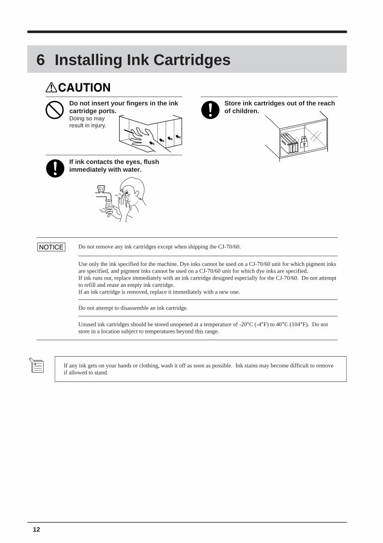
6 Installing Ink Cartridges
Store ink cartridges out of the reachof children.
Do not insert your fingers in the inkcartridge ports.Doing so mayresult in injury.
If ink contacts the eyes, flushimmediately with water.
Do not remove any ink cartridges except when shipping the CJ-70/60.
Use only the ink specified for the machine. Dye inks cannot be used on a CJ-70/60 unit for which pigment inksare specified, and pigment inks cannot be used on a CJ-70/60 unit for which dye inks are specified.If ink runs out, replace immediately with an ink cartridge designed especially for the CJ-70/60. Do not attemptto refill and reuse an empty ink cartridge.If an ink cartridge is removed, replace it immediately with a new one.
Do not attempt to disassemble an ink cartridge.
Unused ink cartridges should be stored unopened at a temperature of -20°C (-4°F) to 40°C (104°F). Do notstore in a location subject to temperatures beyond this range.
If any ink gets on your hands or clothing, wash it off as soon as possible. Ink stains may become difficult to removeif allowed to stand.
13
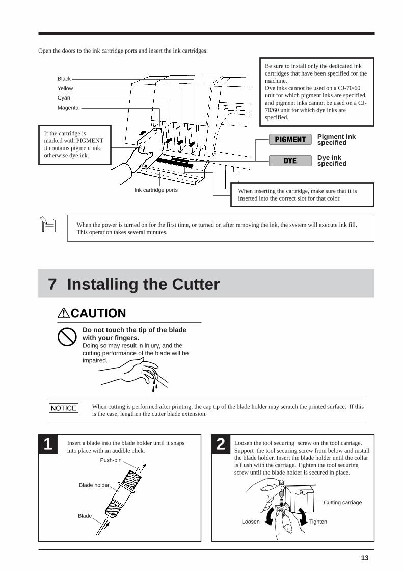
Open the doors to the ink cartridge ports and insert the ink cartridges.
Ink cartridge ports
Yellow
Cyan
Magenta
Black
Pigment inkspecified
Dye inkspecified
Be sure to install only the dedicated inkcartridges that have been specified for themachine.Dye inks cannot be used on a CJ-70/60unit for which pigment inks are specified,and pigment inks cannot be used on a CJ-70/60 unit for which dye inks arespecified.
If the cartridge ismarked with PIGMENTit contains pigment ink,otherwise dye ink.
When the power is turned on for the first time, or turned on after removing the ink, the system will execute ink fill.This operation takes several minutes.
When inserting the cartridge, make sure that it isinserted into the correct slot for that color.
Insert a blade into the blade holder until it snapsinto place with an audible click.1 2 Loosen the tool securing screw on the tool carriage.
Support the tool securing screw from below and installthe blade holder. Insert the blade holder until the collaris flush with the carriage. Tighten the tool securingscrew until the blade holder is secured in place.
Loosen Tighten
Cutting carriage
Push-pin
Blade holder
Blade
7 Installing the Cutter
Do not touch the tip of the bladewith your fingers.Doing so may result in injury, and thecutting performance of the blade will beimpaired.
When cutting is performed after printing, the cap tip of the blade holder may scratch the printed surface. If thisis the case, lengthen the cutter blade extension.
14
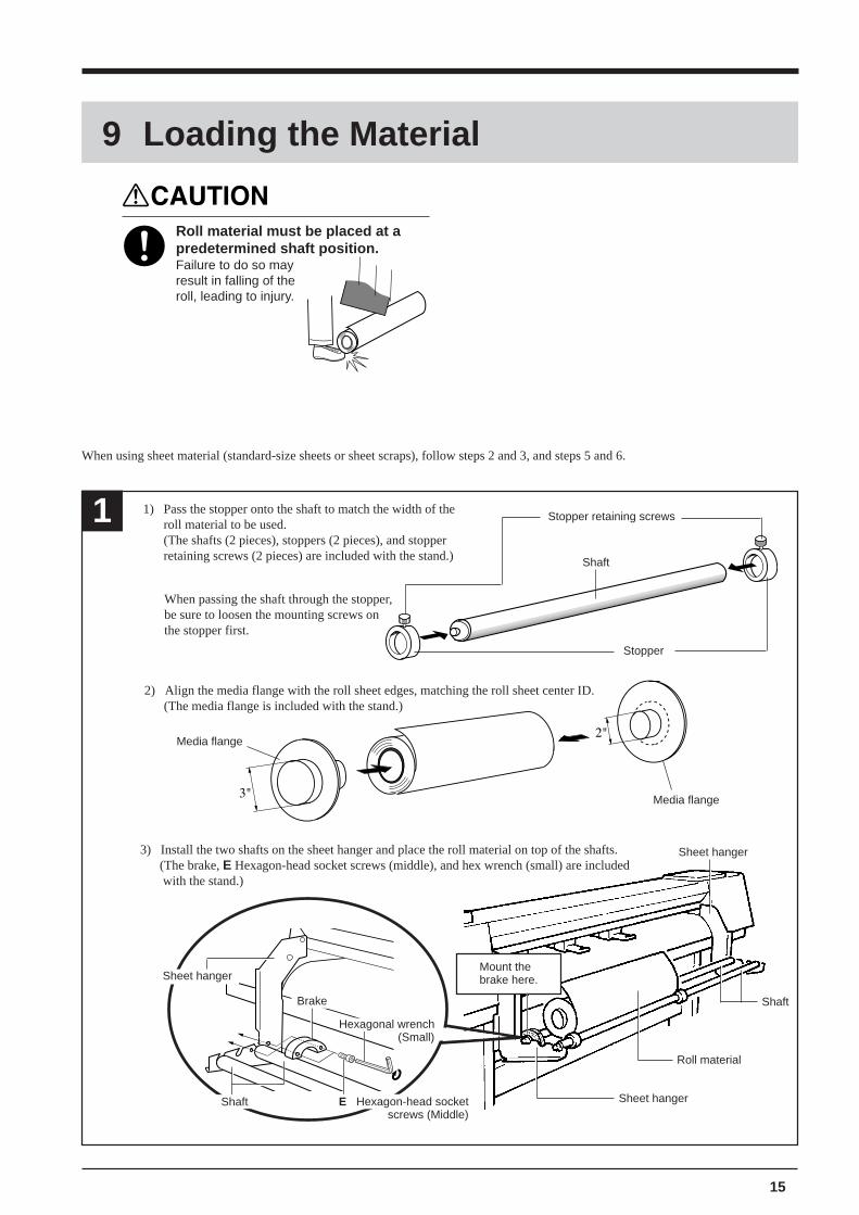
Roland CAMM JETVer.4.00
INSTALL DRAIN TANK
FILL INKNOW PROCESSING..
"SHEET SELECT"
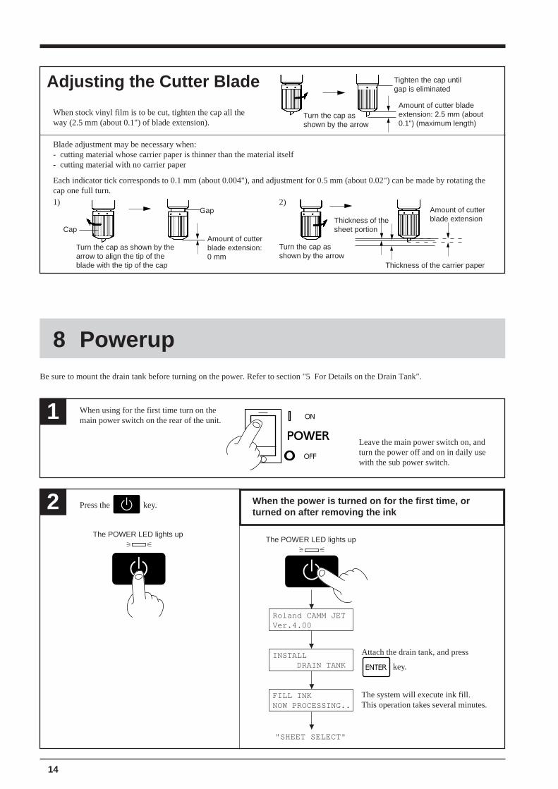
When stock vinyl film is to be cut, tighten the cap all theway (2.5 mm (about 0.1") of blade extension).
Adjusting the Cutter Blade Tighten the cap untilgap is eliminated
Amount of cutter bladeextension: 2.5 mm (about0.1") (maximum length)
Turn the cap asshown by the arrow
1)Gap
Amount of cutterblade extension:0 mm
2)Amount of cutterblade extension
Thickness of the carrier paper
Thickness of thesheet portion
Turn the cap asshown by the arrow
Cap
Blade adjustment may be necessary when:- cutting material whose carrier paper is thinner than the material itself- cutting material with no carrier paper
Each indicator tick corresponds to 0.1 mm (about 0.004"), and adjustment for 0.5 mm (about 0.02") can be made by rotating thecap one full turn.
Turn the cap as shown by thearrow to align the tip of theblade with the tip of the cap
1 When using for the first time turn on themain power switch on the rear of the unit.
Be sure to mount the drain tank before turning on the power. Refer to section "5 For Details on the Drain Tank".
8 Powerup
Leave the main power switch on, andturn the power off and on in daily usewith the sub power switch.
2 Press the key.
The POWER LED lights up
When the power is turned on for the first time, orturned on after removing the ink
The POWER LED lights up
The system will execute ink fill.This operation takes several minutes.
Attach the drain tank, and press
key.
15
Shaft
Sheet hanger
9 Loading the Material
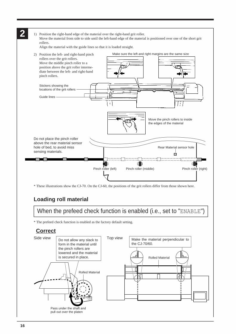
1
When passing the shaft through the stopper,be sure to loosen the mounting screws onthe stopper first.
2) Align the media flange with the roll sheet edges, matching the roll sheet center ID. (The media flange is included with the stand.)
Stopper
Stopper retaining screws
Shaft
Media flange
Media flange
3) Install the two shafts on the sheet hanger and place the roll material on top of the shafts. (The brake, E Hexagon-head socket screws (middle), and hex wrench (small) are included with the stand.)
1) Pass the stopper onto the shaft to match the width of theroll material to be used.(The shafts (2 pieces), stoppers (2 pieces), and stopperretaining screws (2 pieces) are included with the stand.)
Sheet hanger
Roll material
Sheet hanger
Shaft
Hexagonal wrench(Small)
E Hexagon-head socketscrews (Middle)
Mount thebrake here.
Brake
When using sheet material (standard-size sheets or sheet scraps), follow steps 2 and 3, and steps 5 and 6.
Roll material must be placed at apredetermined shaft position.Failure to do so mayresult in falling of theroll, leading to injury.
16
1) Position the right-hand edge of the material over the right-hand grit roller.Move the material from side to side until the left-hand edge of the material is positioned over one of the short gritrollers.Align the material with the guide lines so that it is loaded straight.
2
Pinch roller (left) Pinch roller (right)Pinch roller (middle)
2) Position the left- and right-hand pinchrollers over the grit rollers.Move the middle pinch roller to aposition above the grit roller interme-diate between the left- and right-handpinch rollers.
Make sure the left and right margins are the same size
Stickers showing thelocations of the grit rollers
Move the pinch rollers to insidethe edges of the material
Guide lines
Do not place the pinch rollerabove the rear material sensorhole of bed, to avoid misssensing materials.
Rear Material sensor hole
* These illustrations show the CJ-70. On the CJ-60, the positions of the grit rollers differ from those shown here.
Loading roll material
When the prefeed check function is enabled (i.e., set to "ENABLE")
* The prefeed check function is enabled as the factory default setting.
CorrectSide view Top view
Pass under the shaft andpull out over the platen
Do not allow any slack toform in the material untilthe pinch rollers arelowered and the materialis secured in place.
Rolled Material
Rolled Material
Make the material perpendicular tothe CJ-70/60.
17
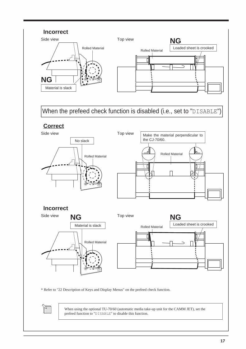
IncorrectSide view Top view
Rolled Material
Material is slack
NG
Rolled MaterialLoaded sheet is crooked
NG
When the prefeed check function is disabled (i.e., set to "DISABLE")
CorrectSide view Top view
No slack
Rolled MaterialRolled Material
Make the material perpendicular tothe CJ-70/60.
IncorrectSide view Top view
Rolled Material
Rolled MaterialLoaded sheet is crooked
NGMaterial is slack
NG
* Refer to "22 Description of Keys and Display Menus" on the prefeed check function.
When using the optional TU-70/60 (automatic media take-up unit for the CAMM JET), set theprefeed function to "DISABLE" to disable this function.
18
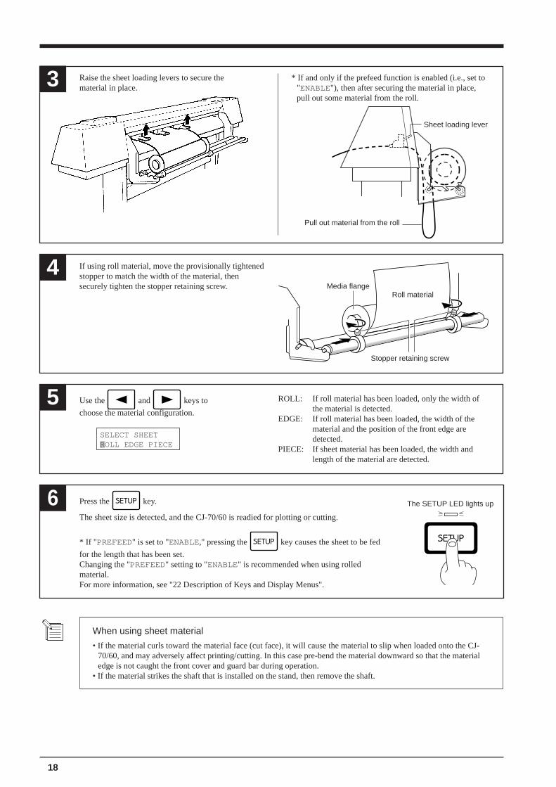
Press the key.
The sheet size is detected, and the CJ-70/60 is readied for plotting or cutting.
* If " PREFEED" is set to "ENABLE," pressing the key causes the sheet to be fed
for the length that has been set.Changing the "PREFEED" setting to "ENABLE" is recommended when using rolledmaterial.For more information, see "22 Description of Keys and Display Menus".
6 The SETUP LED lights up
When using sheet material
• If the material curls toward the material face (cut face), it will cause the material to slip when loaded onto the CJ-70/60, and may adversely affect printing/cutting. In this case pre-bend the material downward so that the materialedge is not caught the front cover and guard bar during operation.
• If the material strikes the shaft that is installed on the stand, then remove the shaft.
Raise the sheet loading levers to secure thematerial in place.3
Use the and keys to
choose the material configuration.5
SELECT SHEETROLL EDGE PIECE
ROLL: If roll material has been loaded, only the width ofthe material is detected.
EDGE: If roll material has been loaded, the width of thematerial and the position of the front edge aredetected.
PIECE: If sheet material has been loaded, the width andlength of the material are detected.
If using roll material, move the provisionally tightenedstopper to match the width of the material, thensecurely tighten the stopper retaining screw.
4Media flange
Stopper retaining screw
Sheet loading lever
* If and only if the prefeed function is enabled (i.e., set to"ENABLE"), then after securing the material in place,pull out some material from the roll.
Pull out material from the roll
Roll material
19
10 Printing Test
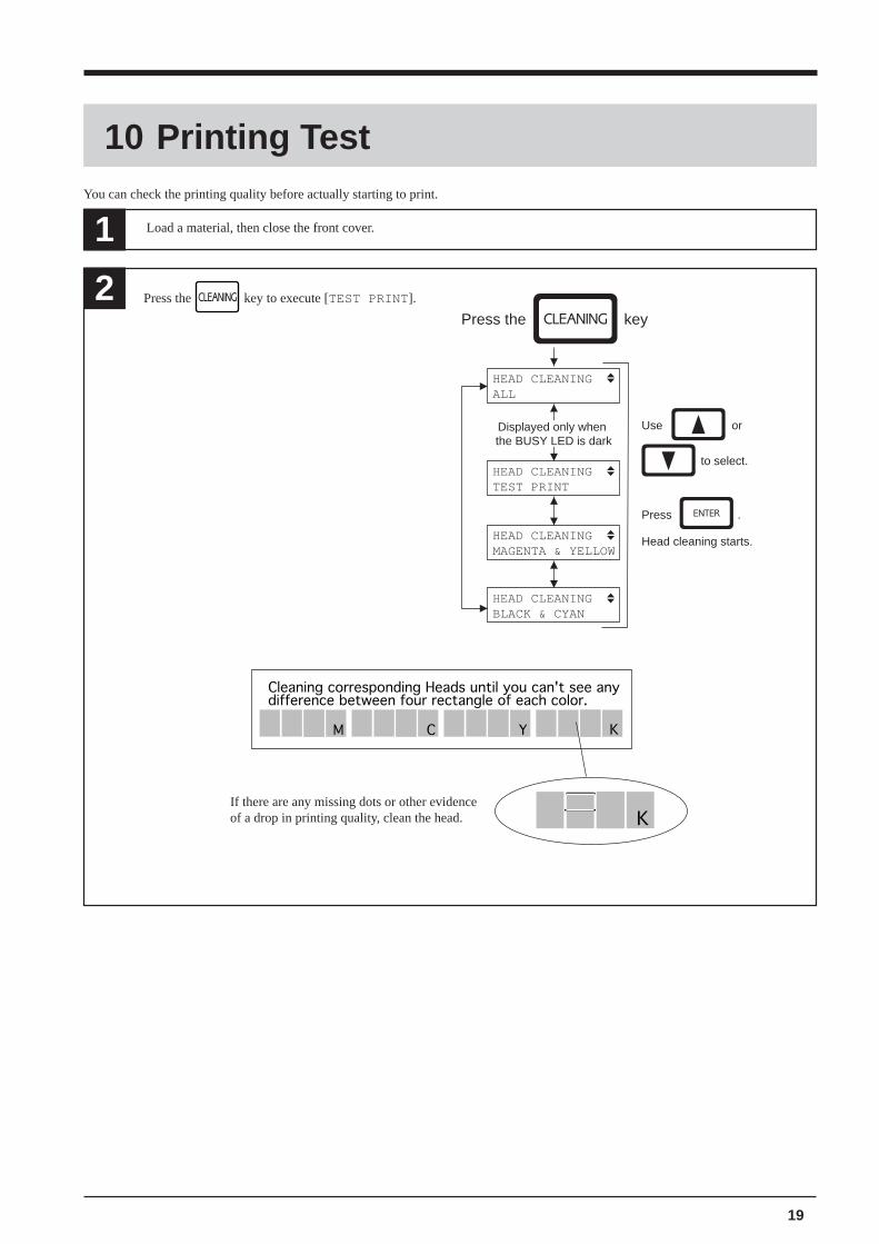
Load a material, then close the front cover.1
2Press the key
HEAD CLEANINGALL
HEAD CLEANINGTEST PRINT
HEAD CLEANINGMAGENTA & YELLOW
HEAD CLEANINGBLACK & CYAN
Use or
to select.
Displayed only when the BUSY LED is dark
Press .
Head cleaning starts.
Cleaning corresponding Heads until you can't see anydifference between four rectangle of each color.
C Y KM
K
You can check the printing quality before actually starting to print.
If there are any missing dots or other evidenceof a drop in printing quality, clean the head.
Press the key to execute [TEST PRINT ].
20
For optimum performance, it is necessary to set cutting conditions that match the material, giving consideration to the material's thick-ness and type of material. The CJ-70/60 has an internal "cutting test" to check the cutting conditions. This "cutting test" allows you todetermine settings for the cutting speed, blade force and the amount of offset.Experiment with different settings for different types of material and adjust the configuration accordingly.
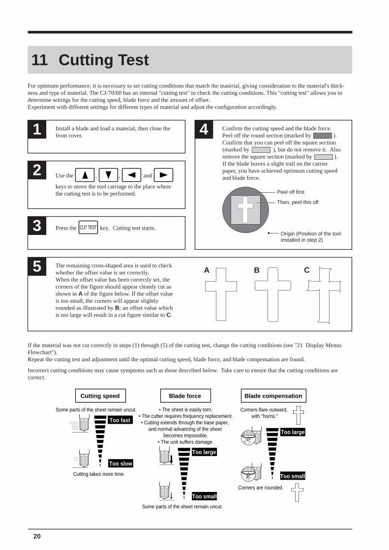
Install a blade and load a material, then close thefront cover.1 4 Confirm the cutting speed and the blade force.
Peel off the round section (marked by ).Confirm that you can peel off the square section(marked by ), but do not remove it. Alsoremove the square section (marked by ).If the blade leaves a slight trail on the carrierpaper, you have achieved optimum cutting speedand blade force.
Then, peel this off
Peel off first
Origin (Position of the toolinstalled in step 2)
2
Press the key. Cutting test starts.3
Use the , , and
keys to move the tool carriage to the place wherethe cutting test is to be performed.
The remaining cross-shaped area is used to checkwhether the offset value is set correctly.When the offset value has been correctly set, thecorners of the figure should appear cleanly cut asshown in A of the figure below. If the offset valueis too small, the corners will appear slightlyrounded as illustrated by B; an offset value whichis too large will result in a cut figure similar to C.
5 A B C
If the material was not cut correctly in steps (1) through (5) of the cutting test, change the cutting conditions (see "21 Display MenusFlowchart").Repeat the cutting test and adjustment until the optimal cutting speed, blade force, and blade compensation are found.
Incorrect cutting conditions may cause symptoms such as those described below. Take care to ensure that the cutting conditions arecorrect.
11 Cutting Test
Cutting speed Blade force Blade compensation
Corners flare outward, with "horns."
Corners are rounded.
Some parts of the sheet remain uncut.
• The sheet is easily torn.• The cutter requires frequency replacement.• Cutting extends through the base paper,
and normal advancing of the sheet becomes impossible.
• The unit suffers damage.
Some parts of the sheet remain uncut.
Cutting takes more time.
Too fast
Too slow
Too large
Too small
Too small
Too large
21
12 Downloading Printing/Cutting Data
13 Ending Cutting and Printing Operations
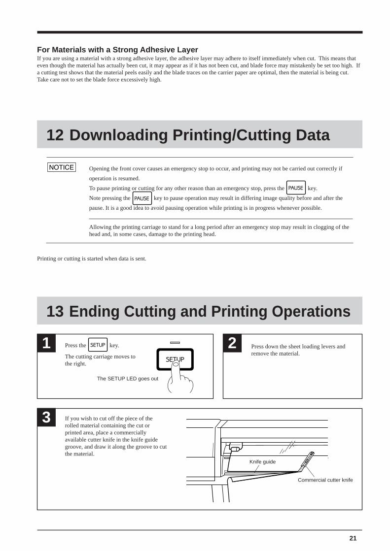
Press the key.
The cutting carriage moves tothe right.
1
The SETUP LED goes out
2 Press down the sheet loading levers andremove the material.
3 If you wish to cut off the piece of therolled material containing the cut orprinted area, place a commerciallyavailable cutter knife in the knife guidegroove, and draw it along the groove to cutthe material.
Knife guide
Commercial cutter knife
For Materials with a Strong Adhesive LayerIf you are using a material with a strong adhesive layer, the adhesive layer may adhere to itself immediately when cut. This means thateven though the material has actually been cut, it may appear as if it has not been cut, and blade force may mistakenly be set too high. Ifa cutting test shows that the material peels easily and the blade traces on the carrier paper are optimal, then the material is being cut.Take care not to set the blade force excessively high.
Opening the front cover causes an emergency stop to occur, and printing may not be carried out correctly if
operation is resumed.
To pause printing or cutting for any other reason than an emergency stop, press the key.
Note pressing the key to pause operation may result in differing image quality before and after the
pause. It is a good idea to avoid pausing operation while printing is in progress whenever possible.
Printing or cutting is started when data is sent.
Allowing the printing carriage to stand for a long period after an emergency stop may result in clogging of thehead and, in some cases, damage to the printing head.
22
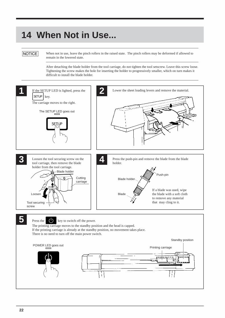
14 When Not in Use...
Loosen the tool securing screw on thetool carriage, then remove the bladeholder from the tool carriage.
3 4 Press the push-pin and remove the blade from the bladeholder.
1 2 Lower the sheet loading levers and remove the material.If the SETUP LED is lighted, press the
key.
The carriage moves to the right.
The SETUP LED goes out
Loosen
Tool securingscrew
Blade holder
Cuttingcarriage
Blade holderPush-pin
If a blade was used, wipethe blade with a soft clothto remove any materialthat may cling to it.
Blade
5 Press the key to switch off the power.
The printing carriage moves to the standby position and the head is capped.If the printing carriage is already at the standby position, no movement takes place.There is no need to turn off the main power switch.
POWER LED goes outPrinting carriage
Standby position
After detaching the blade holder from the tool carriage, do not tighten the tool setscrew. Leave this screw loose.Tightening the screw makes the hole for inserting the holder to progressively smaller, which on turn makes itdifficult to install the blade holder.
When not in use, leave the pinch rollers in the raised state. The pinch rollers may be deformed if allowed toremain in the lowered state.
23
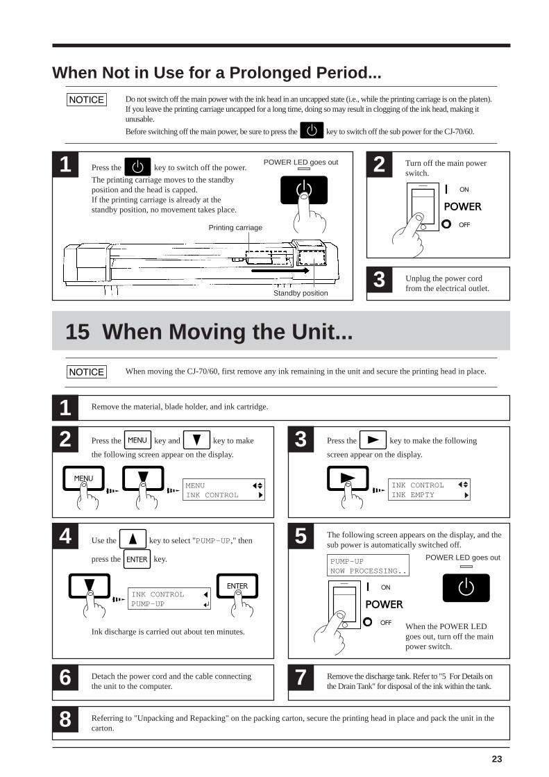
When Not in Use for a Prolonged Period...
15 When Moving the Unit...
1 Press the key to switch off the power.
The printing carriage moves to the standbyposition and the head is capped.If the printing carriage is already at thestandby position, no movement takes place.
POWER LED goes out 2 Turn off the main powerswitch.
3 Unplug the power cordfrom the electrical outlet.
Printing carriage
Standby position
2
INK CONTROLINK EMPTY
3
MENUINK CONTROL
Press the key to make the following
screen appear on the display.
Press the key and key to make
the following screen appear on the display.
4 Use the key to select "PUMP-UP," then
press the key.
The following screen appears on the display, and thesub power is automatically switched off.5
POWER LED goes outPUMP-UPNOW PROCESSING..
8 Referring to "Unpacking and Repacking" on the packing carton, secure the printing head in place and pack the unit in thecarton.
When the POWER LEDgoes out, turn off the mainpower switch.
6 Detach the power cord and the cable connectingthe unit to the computer.
Remove the discharge tank. Refer to "5 For Details onthe Drain Tank" for disposal of the ink within the tank.7
INK CONTROLPUMP-UP
Ink discharge is carried out about ten minutes.
Do not switch off the main power with the ink head in an uncapped state (i.e., while the printing carriage is on the platen).If you leave the printing carriage uncapped for a long time, doing so may result in clogging of the ink head, making itunusable.
Before switching off the main power, be sure to press the key to switch off the sub power for the CJ-70/60.
1 Remove the material, blade holder, and ink cartridge.
When moving the CJ-70/60, first remove any ink remaining in the unit and secure the printing head in place.
24
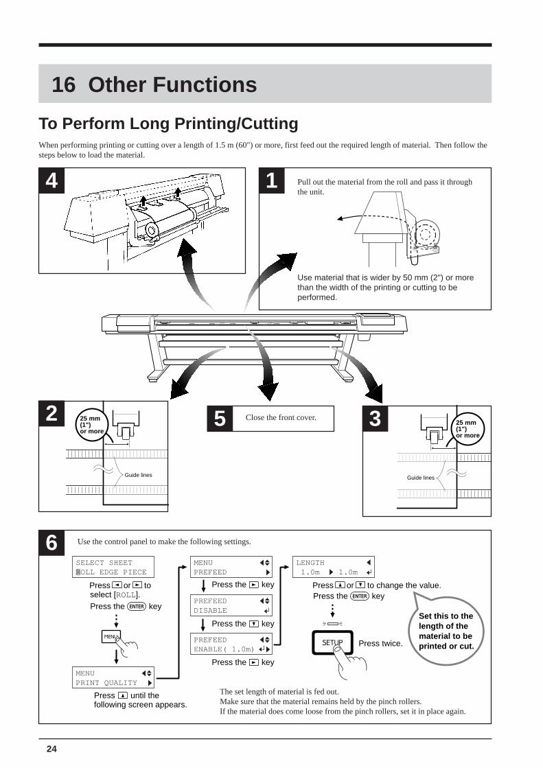
16 Other Functions
To Perform Long Printing/CuttingWhen performing printing or cutting over a length of 1.5 m (60") or more, first feed out the required length of material. Then follow thesteps below to load the material.
Guide lines
25 mm(1")or more
Close the front cover.
Press the key
Press the key
Press the key
Press the keyPress the keyPress or to change the value.Press or to
select [ROLL].
Press twice.
Press until thefollowing screen appears.
Set this to thelength of thematerial to beprinted or cut.
MENUPRINT QUALITY
MENUPREFEED
PREFEEDDISABLE
PREFEEDENABLE( 1.0m)
LENGTH 1.0m 1.0m
SELECT SHEETROLL EDGE PIECE
Use the control panel to make the following settings.
The set length of material is fed out.Make sure that the material remains held by the pinch rollers.If the material does come loose from the pinch rollers, set it in place again.
Pull out the material from the roll and pass it throughthe unit.
Use material that is wider by 50 mm (2") or morethan the width of the printing or cutting to beperformed.
4 1
6
2 3
Guide lines
25 mm(1")or more
5
25
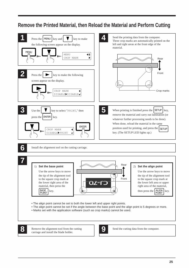
Press the key and key to make
the following screen appear on the display.
1 4 Send the printing data from the computer.Three crop marks are automatically printed on theleft and right areas at the front edge of thematerial.
Press the key to make the following
screen appear on the display.
2
CROP MARKDISABLE DISABLE
3
CROP MARKDISABLE PRINT
5 When printing is finished press the key,
remove the material and carry out lamination (or
whatever further processing needs to be done).
When done, reload the material in the same
position used for printing, and press the
key. (The SETUP LED lights up.)
Rear
Front
Crop marks
Install the alignment tool on the cutting carriage.6
Remove the Printed Material, then Reload the Material and Perform Cutting
7Rear
Front
1) Set the base point
Use the arrow keys to move
the tip of the alignment toolto the square crop mark atthe lower right area of thematerial, then press the
key.
2) Set the align point
Use the arrow keys to move
the tip of the alignment toolto the square crop mark atthe lower left area or upperright area of the material,
then press the key.
• The align point cannot be set to both the lower left and upper right points.• The align point cannot be set if the angle between the base point and the align point is 5 degrees or more.• Marks set with the application software (such as crop marks) cannot be used.
MENUCROP MARK
Remove the alignment tool from the cuttingcarriage and install the blade holder.8 9 Send the cutting data from the computer.
Use the key to select "PRINT," then
press the key.
26
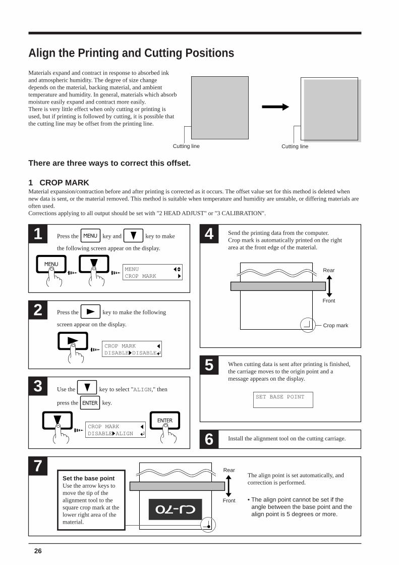
Align the Printing and Cutting PositionsMaterials expand and contract in response to absorbed inkand atmospheric humidity. The degree of size changedepends on the material, backing material, and ambienttemperature and humidity. In general, materials which absorbmoisture easily expand and contract more easily.There is very little effect when only cutting or printing isused, but if printing is followed by cutting, it is possible thatthe cutting line may be offset from the printing line.
Use the key to select "ALIGN," then
press the key.
Press the key and key to make
the following screen appear on the display.
1 4 Send the printing data from the computer.Crop mark is automatically printed on the rightarea at the front edge of the material.
MENUCROP MARK
Press the key to make the following
screen appear on the display.
2
CROP MARKDISABLE DISABLE
3
CROP MARKDISABLE ALIGN
7 Rear
Front
Set the base pointUse the arrow keys tomove the tip of thealignment tool to thesquare crop mark at thelower right area of thematerial.
6 Install the alignment tool on the cutting carriage.
5 When cutting data is sent after printing is finished,the carriage moves to the origin point and amessage appears on the display.
SET BASE POINT
The align point is set automatically, andcorrection is performed.
• The align point cannot be set if theangle between the base point and thealign point is 5 degrees or more.
Rear
Front
Crop mark
1 CROP MARKMaterial expansion/contraction before and after printing is corrected as it occurs. The offset value set for this method is deleted whennew data is sent, or the material removed. This method is suitable when temperature and humidity are unstable, or differing materials areoften used.Corrections applying to all output should be set with "2 HEAD ADJUST" or "3 CALIBRATION".
There are three ways to correct this offset.
Cutting line Cutting line
27
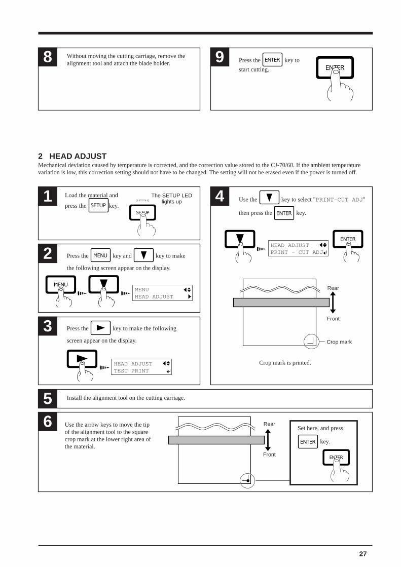
8 Without moving the cutting carriage, remove thealignment tool and attach the blade holder. 9 Press the key to
start cutting.
2 HEAD ADJUSTMechanical deviation caused by temperature is corrected, and the correction value stored to the CJ-70/60. If the ambient temperaturevariation is low, this correction setting should not have to be changed. The setting will not be erased even if the power is turned off.
Press the key and key to make
the following screen appear on the display.
2
1
Press the key to make the following
screen appear on the display.
3
HEAD ADJUSTTEST PRINT
5 Install the alignment tool on the cutting carriage.
Use the key to select "PRINT-CUT ADJ "
then press the key.
4
6
The SETUP LEDlights up
MENUHEAD ADJUST
Rear
Front
Use the arrow keys to move the tipof the alignment tool to the squarecrop mark at the lower right area ofthe material.
HEAD ADJUSTPRINT - CUT ADJ
Rear
Front
Crop mark
Set here, and press
key.
Crop mark is printed.
Load the material and
press the key.
28
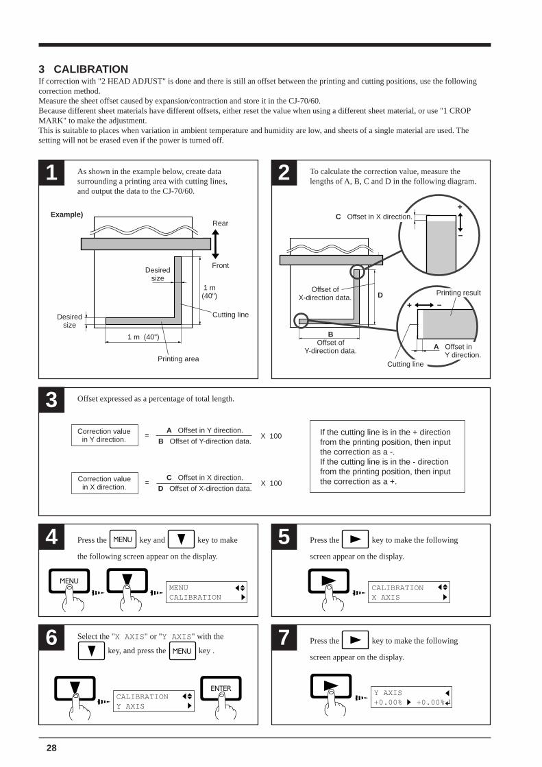
6 Press the key to make the following
screen appear on the display.
7
CALIBRATIONY AXIS
Y AXIS+0.00% +0.00%
3 Offset expressed as a percentage of total length.
4 Press the key to make the following
screen appear on the display.
5
MENUCALIBRATION
CALIBRATIONX AXIS
1 As shown in the example below, create datasurrounding a printing area with cutting lines,and output the data to the CJ-70/60.
2 To calculate the correction value, measure thelengths of A, B, C and D in the following diagram.
Front
Rear
1 m(40")
1 m (40")
+ –
–
+
Cutting line
D
C Offset in X direction.
A Offset in Y direction.
BOffset of
Y-direction data.
Offset ofX-direction data.
Printing result
If the cutting line is in the + directionfrom the printing position, then inputthe correction as a -.If the cutting line is in the - directionfrom the printing position, then inputthe correction as a +.
Correction valuein Y direction.
Correction valuein X direction.
A Offset in Y direction.
B Offset of Y-direction data.= X 100
C Offset in X direction.
D Offset of X-direction data.= X 100
Press the key and key to make
the following screen appear on the display.
Cutting line
Printing area
Desiredsize
Desiredsize
Example)
3 CALIBRATIONIf correction with "2 HEAD ADJUST" is done and there is still an offset between the printing and cutting positions, use the followingcorrection method.Measure the sheet offset caused by expansion/contraction and store it in the CJ-70/60.Because different sheet materials have different offsets, either reset the value when using a different sheet material, or use "1 CROPMARK" to make the adjustment.This is suitable to places when variation in ambient temperature and humidity are low, and sheets of a single material are used. Thesetting will not be erased even if the power is turned off.
Select the "X AXIS " or "Y AXIS " with the
key, and press the key .
29
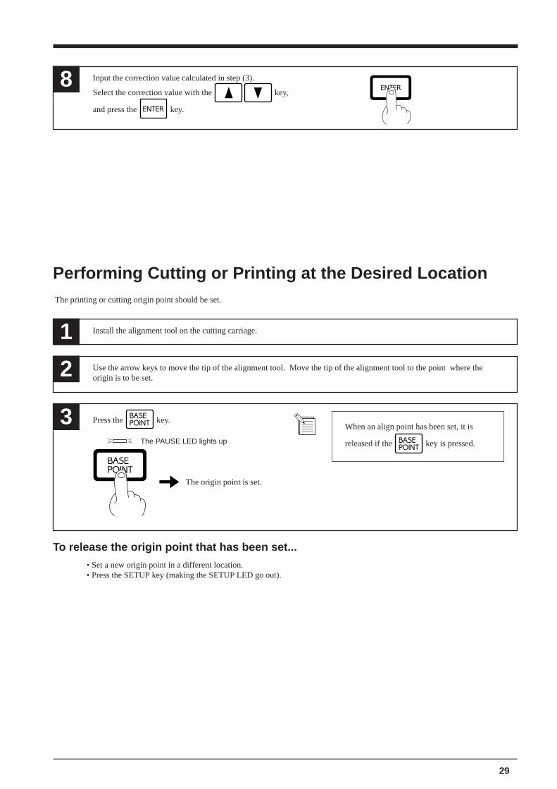
Performing Cutting or Printing at the Desired Location The printing or cutting origin point should be set.
To release the origin point that has been set...
• Set a new origin point in a different location.• Press the SETUP key (making the SETUP LED go out).
1 Install the alignment tool on the cutting carriage.
Use the arrow keys to move the tip of the alignment tool. Move the tip of the alignment tool to the point where theorigin is to be set.2
3 Press the key.
The origin point is set.
The PAUSE LED lights up
When an align point has been set, it is
released if the key is pressed.
8 Input the correction value calculated in step (3).
Select the correction value with the key,
and press the key.
30
17 Maintenance
Replacing the Ink Cartridges
Store ink cartridges out of the reachof children.
Do not insert your fingers in the inkcartridge ports.Doing so mayresult in injury.
If ink contacts the eyes, flushimmediately with water.
Do not remove any ink cartridges except when shipping the CJ-70/60.
Use only the ink specified for the machine. Dye inks cannot be used on a CJ-70/60 unit for which pigment inksare specified, and pigment inks cannot be used on a CJ-70/60 unit for which dye inks are specified.If ink runs out, replace immediately with an ink cartridge designed especially for the CJ-70/60. Do not attemptto refill and reuse an empty ink cartridge.If an ink cartridge is removed, replace it immediately with a new one.
Do not attempt to disassemble an ink cartridge.
Unused ink cartridges should be stored unopened at a temperature of -20°C (-4°F) to 40°C (104°F). Do notstore in a location subject to temperatures beyond this range.
If any ink gets on your hands or clothing, wash it off as soon as possible. Ink stains may become difficult to removeif allowed to stand.
When removing an ink cartridge, do not rush. Detach the cartridge gently. Sudden movement when detachingmay cause ink to be spilled.
31
If the "INK EMPTY" message appears during setupA cartridge has run out of ink, and printing cannot be started.If printing data is being sent, this message is displayed and the buzzer sounds. At the same time, operation is paused and the PAUSELED flashes. Replace the empty cartridge with a new one and press the PAUSE key to start printing.If the data being sent is cutting data only, the message is displayed and the bell sounds, but cutting is started.
Replacing the BladeRefer to "14 When Not in Use..." to remove the blade.See "7 Installing the Cutter" for a description of how to install a blade.
1 PAUSE LED lights upPress the key
to pause printing.
2 Pull out the cartridge for the ink color that has runout, and replace with a new cartridge.
3 PAUSE LED goes outPress the key to
resume printing.
* When "INK EMPTY" is set to "PROMPT", theunit pauses automatically when this message isdisplayed.
The unit is almost out of ink. Please replace the ink cartridge.If this message is ignored and printing is continued without replacing the ink cartridge, image quality may be adversely affected andexhibit faintness or other problems.
If the "INK EMPTY" message appears while printingIf it becomes necessary to replace the ink cartridge while printing is in progress, the following message is displayed and the buzzersounds.
INK EMPTY ******* INK
The color of the ink that has run out is displayed.
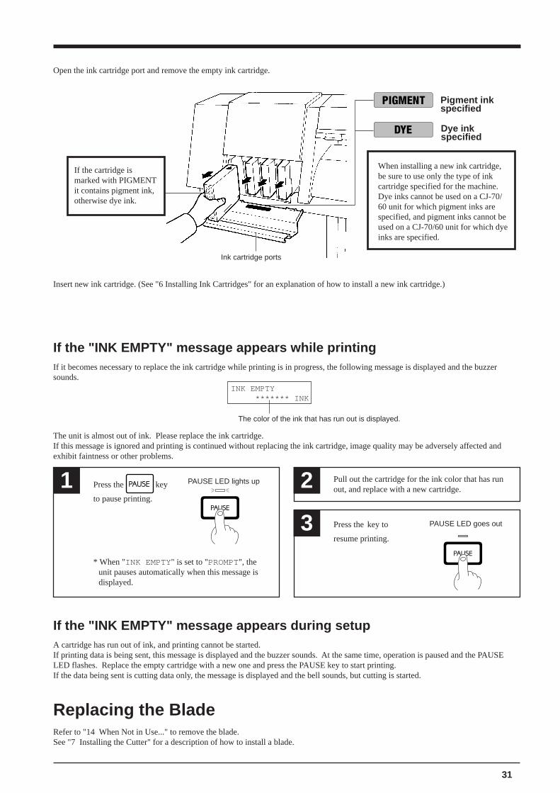
Open the ink cartridge port and remove the empty ink cartridge.
Pigment inkspecified
Insert new ink cartridge. (See "6 Installing Ink Cartridges" for an explanation of how to install a new ink cartridge.)
Ink cartridge ports
When installing a new ink cartridge,be sure to use only the type of inkcartridge specified for the machine.Dye inks cannot be used on a CJ-70/60 unit for which pigment inks arespecified, and pigment inks cannot beused on a CJ-70/60 unit for which dyeinks are specified.
If the cartridge ismarked with PIGMENTit contains pigment ink,otherwise dye ink.
Dye inkspecified
32
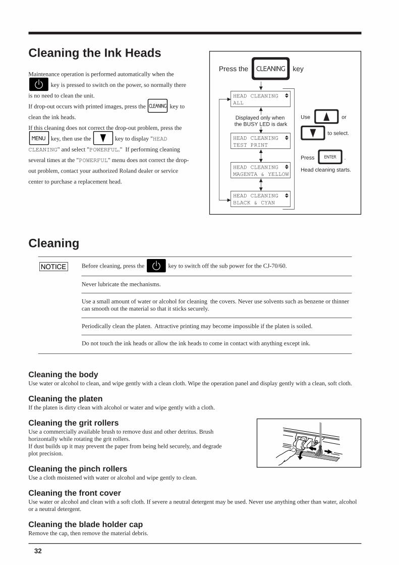
Press the key
HEAD CLEANINGALL
HEAD CLEANINGTEST PRINT
HEAD CLEANINGMAGENTA & YELLOW
HEAD CLEANINGBLACK & CYAN
Use or
to select.
Displayed only when the BUSY LED is dark
Press .
Head cleaning starts.
Cleaning the bodyUse water or alcohol to clean, and wipe gently with a clean cloth. Wipe the operation panel and display gently with a clean, soft cloth.
Cleaning the platenIf the platen is dirty clean with alcohol or water and wipe gently with a cloth.
Cleaning the grit rollersUse a commercially available brush to remove dust and other detritus. Brushhorizontally while rotating the grit rollers.If dust builds up it may prevent the paper from being held securely, and degradeplot precision.
Cleaning the pinch rollersUse a cloth moistened with water or alcohol and wipe gently to clean.
Cleaning the front coverUse water or alcohol and clean with a soft cloth. If severe a neutral detergent may be used. Never use anything other than water, alcoholor a neutral detergent.
Cleaning the blade holder capRemove the cap, then remove the material debris.
Cleaning
Cleaning the Ink Heads
Maintenance operation is performed automatically when the
key is pressed to switch on the power, so normally there
is no need to clean the unit.
If drop-out occurs with printed images, press the key to
clean the ink heads.
If this cleaning does not correct the drop-out problem, press the
key, then use the key to display "HEAD
CLEANING" and select "POWERFUL." If performing cleaning
several times at the "POWERFUL" menu does not correct the drop-
out problem, contact your authorized Roland dealer or service
center to purchase a replacement head.
Never lubricate the mechanisms.
Use a small amount of water or alcohol for cleaning the covers. Never use solvents such as benzene or thinnercan smooth out the material so that it sticks securely.
Before cleaning, press the key to switch off the sub power for the CJ-70/60.
Periodically clean the platen. Attractive printing may become impossible if the platen is soiled.
Do not touch the ink heads or allow the ink heads to come in contact with anything except ink.
33
CJ-70
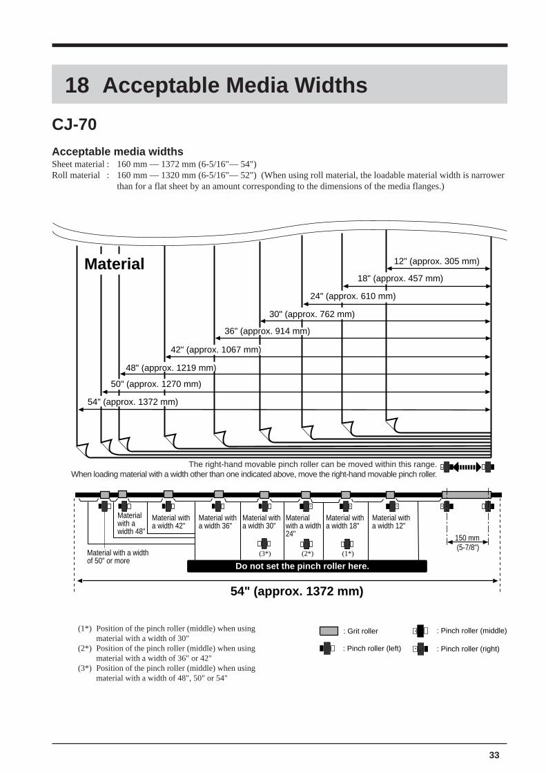
Acceptable media widthsSheet material : 160 mm — 1372 mm (6-5/16"— 54")Roll material : 160 mm — 1320 mm (6-5/16"— 52") (When using roll material, the loadable material width is narrower
than for a flat sheet by an amount corresponding to the dimensions of the media flanges.)
18 Acceptable Media Widths
Do not set the pinch roller here.
54" (approx. 1372 mm)
12" (approx. 305 mm)
42" (approx. 1067 mm)
36" (approx. 914 mm)
30" (approx. 762 mm)
24" (approx. 610 mm)
(1*)(2*)(3*)
Material18" (approx. 457 mm)
54" (approx. 1372 mm)
50" (approx. 1270 mm)
150 mm
48" (approx. 1219 mm)
Material with a width 48"
Material with a width of 50" or more
Material with a width 42"
Material with a width 36"
Material with a width 30"
Material with a width 24"
Material with a width 18"
Material with a width 12"
(5-7/8")
(1*) Position of the pinch roller (middle) when usingmaterial with a width of 30"
(2*) Position of the pinch roller (middle) when usingmaterial with a width of 36" or 42"
(3*) Position of the pinch roller (middle) when usingmaterial with a width of 48", 50" or 54"
The right-hand movable pinch roller can be moved within this range.When loading material with a width other than one indicated above, move the right-hand movable pinch roller.
: Grit roller
: Pinch roller (left) : Pinch roller (right)
: Pinch roller (middle)
34
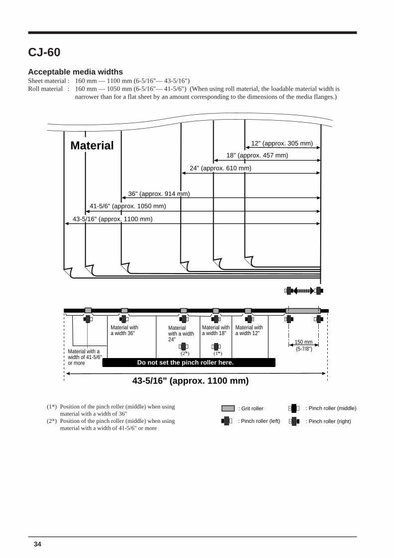
CJ-60
Acceptable media widthsSheet material : 160 mm — 1100 mm (6-5/16"— 43-5/16")Roll material : 160 mm — 1050 mm (6-5/16"— 41-5/6") (When using roll material, the loadable material width is
narrower than for a flat sheet by an amount corresponding to the dimensions of the media flanges.)
(1*) Position of the pinch roller (middle) when usingmaterial with a width of 36"
(2*) Position of the pinch roller (middle) when usingmaterial with a width of 41-5/6" or more
: Grit roller
: Pinch roller (left) : Pinch roller (right)
: Pinch roller (middle)
Do not set the pinch roller here.
43-5/16" (approx. 1100 mm)
12" (approx. 305 mm)
41-5/6" (approx. 1050 mm)
36" (approx. 914 mm)
24" (approx. 610 mm)
(1*)(2*)
Material18" (approx. 457 mm)
150 mm
43-5/16" (approx. 1100 mm)
Material with a width 36"
Material with a width 24"
Material with a width 18"
Material with a width 12"
(5-7/8")Material with a width of 41-5/6" or more
35
C
D
A B
19 Blades and Materials
edalB lairetaM ecrofedalB deepsgnittuC noitasnepmocedalB edalbafoefiL
5001U-CEZ lynivegangislareneG fg051—05 ).ces/"464.33(.ces/mc58 )"48900.0(mm52.0 )"069413(m0008
lynivegangislareneG fg001—03
5205U-CEZ lynivevitcelfeR fg002—021 ).ces/"464.33(.ces/mc58 )"48900.0(mm52.0 )"084751(m0004
lynivtnecseroulF fg002—001
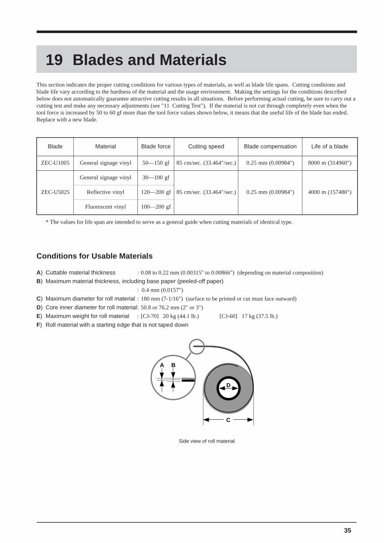
This section indicates the proper cutting conditions for various types of materials, as well as blade life spans. Cutting conditions andblade life vary according to the hardness of the material and the usage environment. Making the settings for the conditions describedbelow does not automatically guarantee attractive cutting results in all situations. Before performing actual cutting, be sure to carry out acutting test and make any necessary adjustments (see "11 Cutting Test"). If the material is not cut through completely even when thetool force is increased by 50 to 60 gf more than the tool force values shown below, it means that the useful life of the blade has ended.Replace with a new blade.
* The values for life span are intended to serve as a general guide when cutting materials of identical type.
Conditions for Usable Materials
A) Cuttable material thickness : 0.08 to 0.22 mm (0.00315" to 0.00866") (depending on material composition)
B) Maximum material thickness, including base paper (peeled-off paper)
: 0.4 mm (0.0157")
C) Maximum diameter for roll material : 180 mm (7-1/16") (surface to be printed or cut must face outward)
D) Core inner diameter for roll material: 50.8 or 76.2 mm (2" or 3")
E) Maximum weight for roll material : [CJ-70] 20 kg (44.1 lb.) [CJ-60] 17 kg (37.5 lb.)
F) Roll material with a starting edge that is not taped down
Side view of roll material
36
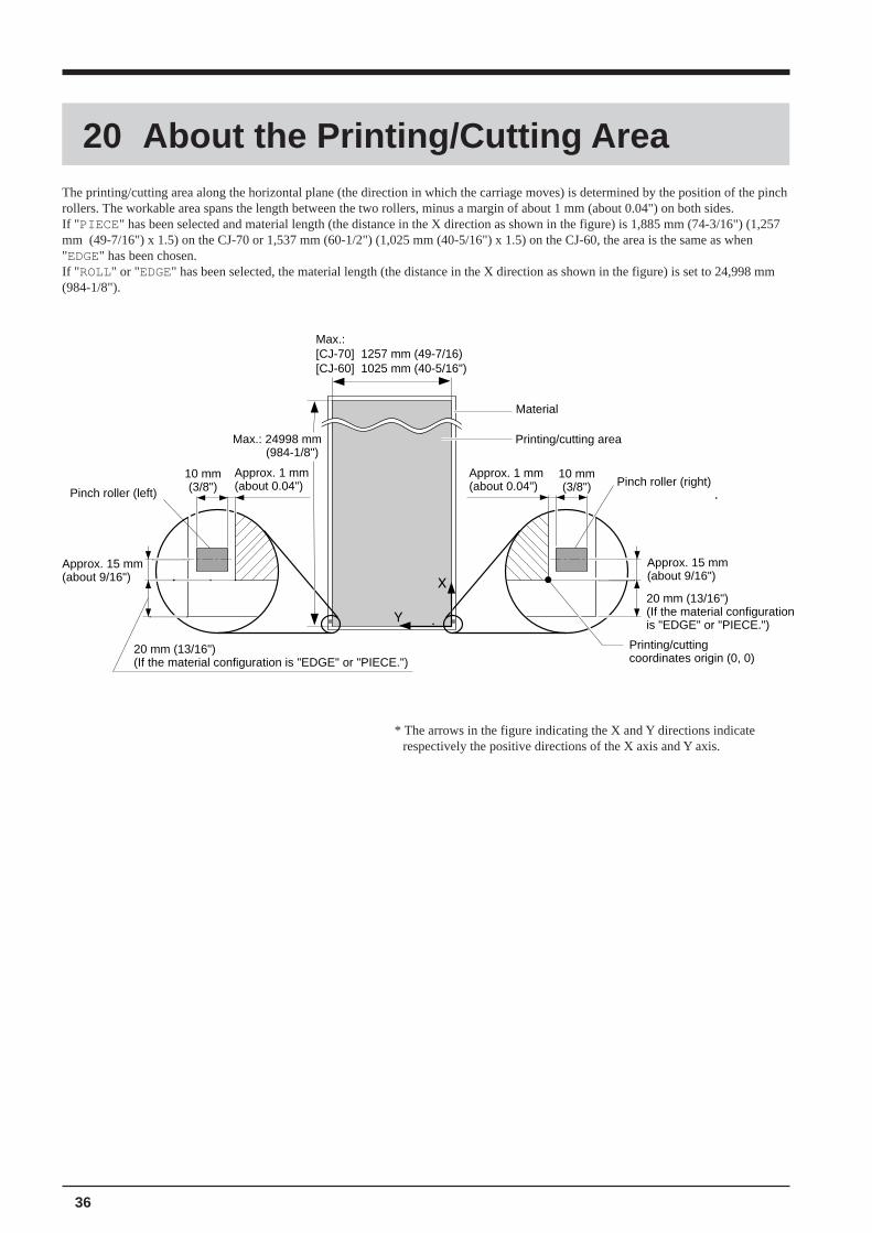
20 About the Printing/Cutting AreaThe printing/cutting area along the horizontal plane (the direction in which the carriage moves) is determined by the position of the pinchrollers. The workable area spans the length between the two rollers, minus a margin of about 1 mm (about 0.04") on both sides.If " PIECE" has been selected and material length (the distance in the X direction as shown in the figure) is 1,885 mm (74-3/16") (1,257mm (49-7/16") x 1.5) on the CJ-70 or 1,537 mm (60-1/2") (1,025 mm (40-5/16") x 1.5) on the CJ-60, the area is the same as when"EDGE" has been chosen.If " ROLL" or "EDGE" has been selected, the material length (the distance in the X direction as shown in the figure) is set to 24,998 mm(984-1/8").
* The arrows in the figure indicating the X and Y directions indicaterespectively the positive directions of the X axis and Y axis.
Printing/cutting coordinates origin (0, 0)
20 mm (13/16")(If the material configuration is "EDGE" or "PIECE.")
Approx. 15 mm(about 9/16")
Pinch roller (right)10 mm(3/8")
Approx. 1 mm (about 0.04")
Printing/cutting area
Material
Max.: [CJ-70] 1257 mm (49-7/16)[CJ-60] 1025 mm (40-5/16")
Max.: 24998 mm (984-1/8")
Pinch roller (left)
10 mm(3/8")
Approx. 1 mm (about 0.04")
Approx. 15 mm(about 9/16")
20 mm (13/16")(If the material configuration is "EDGE" or "PIECE.")
37
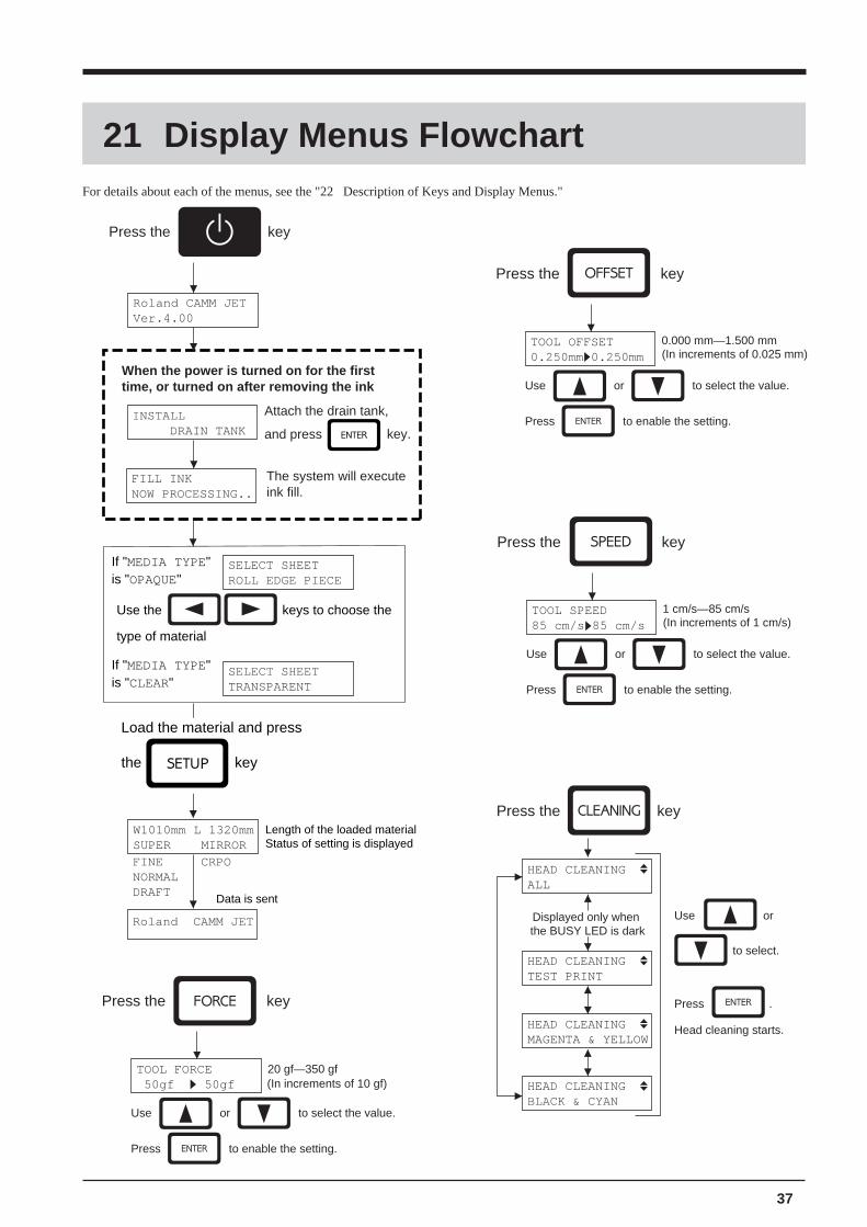
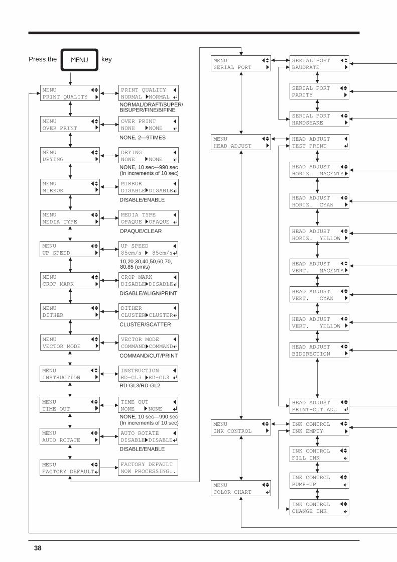
21 Display Menus FlowchartFor details about each of the menus, see the "22 Description of Keys and Display Menus."
TOOL OFFSET0.250mm 0.250mm
0.000 mm—1.500 mm(In increments of 0.025 mm)
Press the key
Use or to select the value.
Press to enable the setting.
Press the key
HEAD CLEANINGALL
HEAD CLEANINGTEST PRINT
HEAD CLEANINGMAGENTA & YELLOW
HEAD CLEANINGBLACK & CYAN
Use or
to select.
Displayed only when the BUSY LED is dark
Press .
Head cleaning starts.
Use the keys to choose the
type of material
Roland CAMM JETVer.4.00
Press the key
Roland CAMM JET
Load the material and press
the key
W1010mm L 1320mmSUPER MIRROR
FINE CRPONORMALDRAFT
Length of the loaded materialStatus of setting is displayed
Data is sent
SELECT SHEETROLL EDGE PIECE
SELECT SHEETTRANSPARENT
If "MEDIA TYPE" is "OPAQUE"
If "MEDIA TYPE" is "CLEAR"
INSTALL DRAIN TANK
When the power is turned on for the first time, or turned on after removing the ink
Attach the drain tank,
and press
FILL INKNOW PROCESSING..
The system will execute ink fill.
key.
Press the key
20 gf—350 gf(In increments of 10 gf)
TOOL FORCE 50gf 50gf
Use or to select the value.
Press to enable the setting.
TOOL SPEED85 cm/s 85 cm/s
1 cm/s—85 cm/s(In increments of 1 cm/s)
Press the key
Use or to select the value.
Press to enable the setting.
38
MENUHEAD ADJUST
HEAD ADJUSTTEST PRINT
HEAD ADJUSTHORIZ. MAGENTA
HEAD ADJUSTHORIZ. CYAN
HEAD ADJUSTHORIZ. YELLOW
HEAD ADJUSTVERT. MAGENTA
HEAD ADJUSTVERT. CYAN
HEAD ADJUSTVERT. YELLOW
HEAD ADJUSTBIDIRECTION
HEAD ADJUSTPRINT-CUT ADJ
MENUINK CONTROL
INK CONTROLINK EMPTY
INK CONTROLFILL INK
MENUCOLOR CHART
INK CONTROLPUMP-UP
MENUPRINT QUALITY
PRINT QUALITYNORMAL NORMAL
MENUDRYING
DRYINGNONE NONE
MENUMIRROR
MIRRORDISABLE DISABLE
MENUMEDIA TYPE
MEDIA TYPEOPAQUE OPAQUE
MENUCROP MARK
CROP MARKDISABLE>DISABLE
MENUDITHER
DITHERCLUSTER>CLUSTER
MENUVECTOR MODE
VECTOR MODECOMMAND COMMAND
MENUTIME OUT
TIME OUTNONE NONE
MENUAUTO ROTATE
AUTO ROTATEDISABLE>DISABLE
MENUFACTORY DEFAULT
MENUSERIAL PORT
SERIAL PORTBAUDRATE
SERIAL PORTPARITY
SERIAL PORTHANDSHAKE
FACTORY DEFAULTNOW PROCESSING..
MENUOVER PRINT
OVER PRINTNONE NONE
MENUUP SPEED
UP SPEED85cm/s 85cm/s
MENUINSTRUCTION
INSTRUCTIONRD-GL3 RD-GL3
INK CONTROLCHANGE INK
NONE, 10 sec—990 sec(In increments of 10 sec)
DISABLE/ENABLE
NONE, 10 sec—990 sec(In increments of 10 sec)
DISABLE/ENABLE
OPAQUE/CLEAR
DISABLE/ALIGN/PRINT
CLUSTER/SCATTER
COMMAND/CUT/PRINT
Press the key
NORMAL/DRAFT/SUPER/BISUPER/FINE/BIFINE
10,20,30,40,50,60,70,80,85 (cm/s)
RD-GL3/RD-GL2
NONE, 2—9TIMES
39
HORIZ. MAGENTA +0 > +0
HORIZ. CYAN +0 > +0
HORIZ. YELLOW +0 > +0
VERT. MAGENTA +0 > +0
VERT. CYAN +0 > +0
VERT. YELLOW +0 > +0
BIDIRECTION +0.0 > +0.0
PRINT-CUT ADJ BY CURSOR
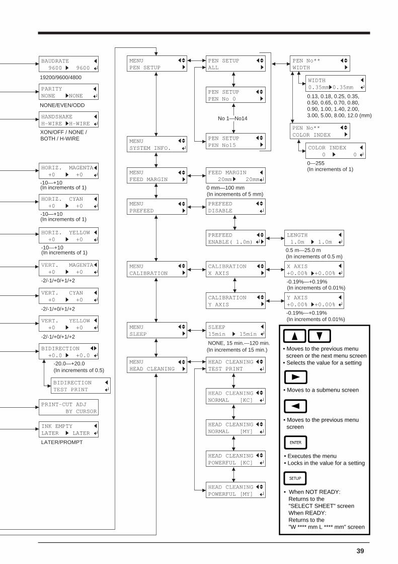
MENUPEN SETUP
PEN SETUPALL
PEN SETUPPEN No 0
PEN No**COLOR INDEX
PEN SETUPPEN No15
PEN No**WIDTH
WIDTH0.35mm>0.35mm
COLOR INDEX 0 > 0
PREFEEDENABLE( 1.0m)
LENGTH 1.0m 1.0m
MENUCALIBRATION
CALIBRATIONX AXIS
X AXIS+0.00% >+0.00%
CALIBRATIONY AXIS
Y AXIS+0.00% >+0.00%
MENUSLEEP
SLEEP15min 15min
MENUHEAD CLEANING
HEAD CLEANINGTEST PRINT
HEAD CLEANINGNORMAL [KC]
HEAD CLEANINGNORMAL [MY]
HEAD CLEANINGPOWERFUL [KC]
HEAD CLEANINGPOWERFUL [MY]
MENUSYSTEM INFO.
MENUPREFEED
PREFEEDDISABLE
INK EMPTYLATER > LATER
BAUDRATE 9600 > 9600
PARITYNONE >NONE
HANDSHAKEH-WIRE >H-WIRE
BIDIRECTIONTEST PRINT
-10—+10(In increments of 1)
-10—+10(In increments of 1)
-10—+10(In increments of 1)
-2/-1/+0/+1/+2
-2/-1/+0/+1/+2
-2/-1/+0/+1/+2
-20.0—+20.0(In increments of 0.5)
No 1—No14
0.13, 0.18, 0.25, 0.35, 0.50, 0.65, 0.70, 0.80, 0.90, 1.00, 1.40, 2.00, 3.00, 5.00, 8.00, 12.0 (mm)
0—255(In increments of 1)
0.5 m—25.0 m(In increments of 0.5 m)
-0.19%—+0.19%(In increments of 0.01%)
-0.19%—+0.19%(In increments of 0.01%)
NONE, 15 min.—120 min.(In increments of 15 min.)
19200/9600/4800
NONE/EVEN/ODD
XON/OFF / NONE /BOTH / H-WIRE
LATER/PROMPT
MENUFEED MARGIN
FEED MARGIN 20mm 20mm
0 mm—100 mm(In increments of 5 mm)
• Moves to the previous menu screen or the next menu screen• Selects the value for a setting
• Moves to a submenu screen
• Moves to the previous menu screen
• Executes the menu• Locks in the value for a setting
• When NOT READY: Returns to the "SELECT SHEET" screen When READY: Returns to the "W **** mm L **** mm" screen
40
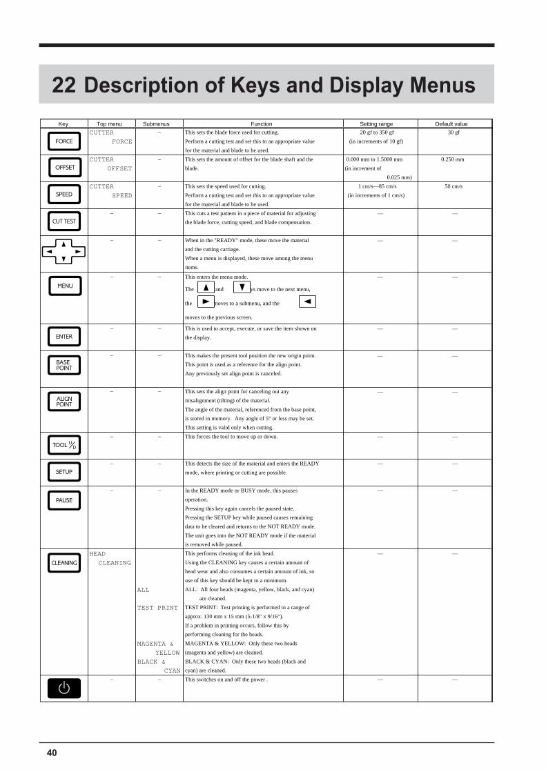
Key Top menu Submenus Function Setting range Default value
CUTTER — This sets the blade force used for cutting. 20 gf to 350 gf 30 gf
FORCE Perform a cutting test and set this to an appropriate value (in increments of 10 gf)
for the material and blade to be used.
CUTTER — This sets the amount of offset for the blade shaft and the 0.000 mm to 1.5000 mm 0.250 mm
OFFSET blade. (in increment of
0.025 mm)
CUTTER — This sets the speed used for cutting. 1 cm/s—85 cm/s 50 cm/s
SPEED Perform a cutting test and set this to an appropriate value (in increments of 1 cm/s)
for the material and blade to be used.
— — This cuts a test pattern in a piece of material for adjusting — —
the blade force, cutting speed, and blade compensation.
— — When in the "READY" mode, these move the material — —
and the cutting carriage.
When a menu is displayed, these move among the menu
items.
— — This enters the menu mode. — —
The and keys move to the next menu,
the moves to a submenu, and the key
moves to the previous screen.
— — This is used to accept, execute, or save the item shown on — —
the display.
— — This makes the present tool position the new origin point. — —
This point is used as a reference for the align point.
Any previously set align point is canceled.
— — This sets the align point for canceling out any — —
misalignment (tilting) of the material.
The angle of the material, referenced from the base point,
is stored in memory. Any angle of 5° or less may be set.
This setting is valid only when cutting.
— — This forces the tool to move up or down. — —
— — This detects the size of the material and enters the READY — —
mode, where printing or cutting are possible.
— — In the READY mode or BUSY mode, this pauses — —
operation.
Pressing this key again cancels the paused state.
Pressing the SETUP key while paused causes remaining
data to be cleared and returns to the NOT READY mode.
The unit goes into the NOT READY mode if the material
is removed while paused.
HEAD This performs cleaning of the ink head. — —
CLEANING Using the CLEANING key causes a certain amount of
head wear and also consumes a certain amount of ink, so
use of this key should be kept to a minimum.
ALL ALL: All four heads (magenta, yellow, black, and cyan)
are cleaned.
TEST PRINT TEST PRINT: Test printing is performed in a range of
approx. 130 mm x 15 mm (5-1/8" x 9/16").
If a problem in printing occurs, follow this by
performing cleaning for the heads.
MAGENTA & MAGENTA & YELLOW: Only these two heads
YELLOW (magenta and yellow) are cleaned.
BLACK & BLACK & CYAN: Only these two heads (black and
CYAN cyan) are cleaned.
— — This switches on and off the power . — —
22 Description of Keys and Display Menus
41
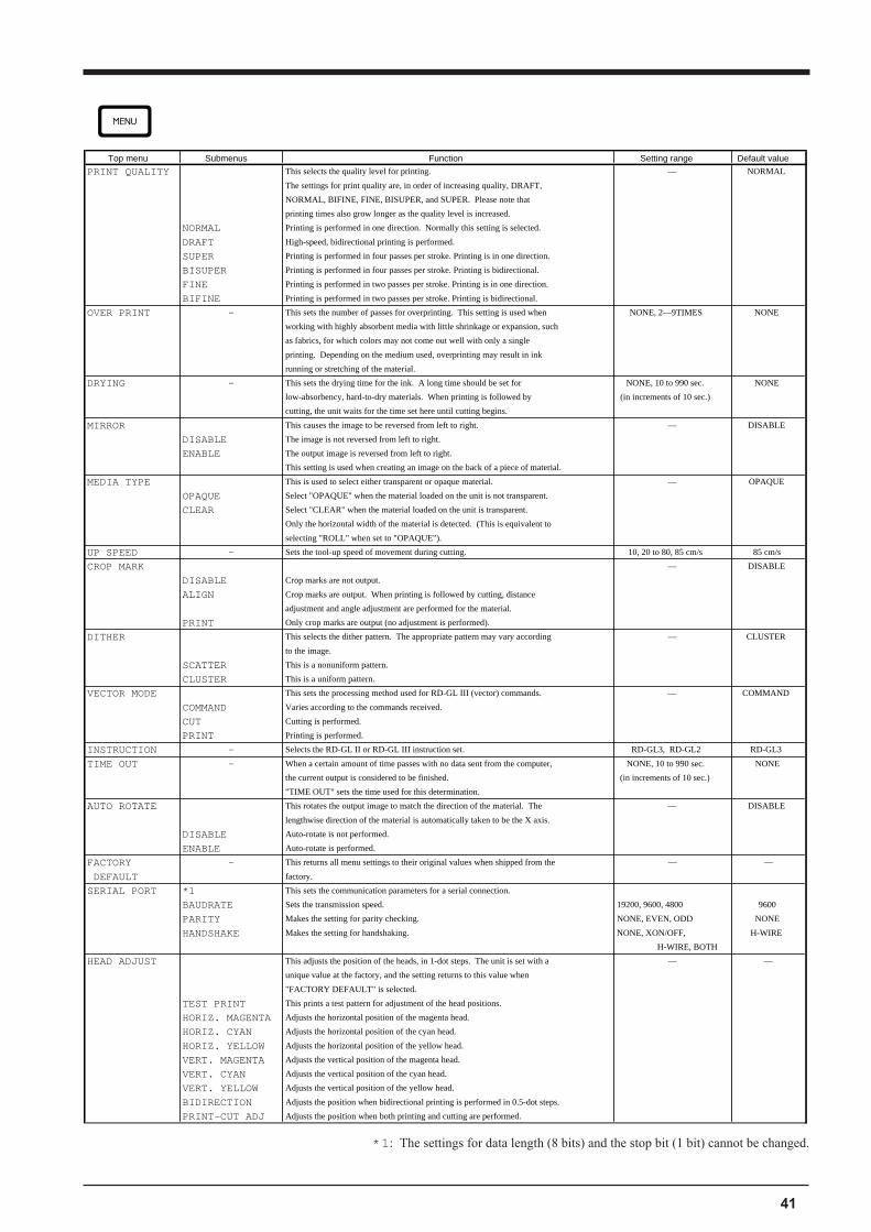
*1: The settings for data length (8 bits) and the stop bit (1 bit) cannot be changed.
Top menu Submenus Function Setting range Default value
PRINT QUALITY This selects the quality level for printing. — NORMAL
The settings for print quality are, in order of increasing quality, DRAFT,
NORMAL, BIFINE, FINE, BISUPER, and SUPER. Please note that
printing times also grow longer as the quality level is increased.
NORMAL Printing is performed in one direction. Normally this setting is selected.
DRAFT High-speed, bidirectional printing is performed.
SUPER Printing is performed in four passes per stroke. Printing is in one direction.
BISUPER Printing is performed in four passes per stroke. Printing is bidirectional.
FINE Printing is performed in two passes per stroke. Printing is in one direction.
BIFINE Printing is performed in two passes per stroke. Printing is bidirectional.
OVER PRINT — This sets the number of passes for overprinting. This setting is used when NONE, 2—9TIMES NONE
working with highly absorbent media with little shrinkage or expansion, such
as fabrics, for which colors may not come out well with only a single
printing. Depending on the medium used, overprinting may result in ink
running or stretching of the material.
DRYING — This sets the drying time for the ink. A long time should be set for NONE, 10 to 990 sec. NONE
low-absorbency, hard-to-dry materials. When printing is followed by (in increments of 10 sec.)
cutting, the unit waits for the time set here until cutting begins.
MIRROR This causes the image to be reversed from left to right. — DISABLE
DISABLE The image is not reversed from left to right.
ENABLE The output image is reversed from left to right.
This setting is used when creating an image on the back of a piece of material.
MEDIA TYPE This is used to select either transparent or opaque material. — OPAQUE
OPAQUE Select "OPAQUE" when the material loaded on the unit is not transparent.
CLEAR Select "CLEAR" when the material loaded on the unit is transparent.
Only the horizontal width of the material is detected. (This is equivalent to
selecting "ROLL" when set to "OPAQUE").
UP SPEED — Sets the tool-up speed of movement during cutting. 10, 20 to 80, 85 cm/s 85 cm/s
CROP MARK — DISABLE
DISABLE Crop marks are not output.
ALIGN Crop marks are output. When printing is followed by cutting, distance
adjustment and angle adjustment are performed for the material.
PRINT Only crop marks are output (no adjustment is performed).
DITHER This selects the dither pattern. The appropriate pattern may vary according — CLUSTER
to the image.
SCATTER This is a nonuniform pattern.
CLUSTER This is a uniform pattern.
VECTOR MODE This sets the processing method used for RD-GL III (vector) commands. — COMMAND
COMMAND Varies according to the commands received.
CUT Cutting is performed.
PRINT Printing is performed.
INSTRUCTION — Selects the RD-GL II or RD-GL III instruction set. RD-GL3, RD-GL2 RD-GL3
TIME OUT — When a certain amount of time passes with no data sent from the computer, NONE, 10 to 990 sec. NONE
the current output is considered to be finished. (in increments of 10 sec.)
"TIME OUT" sets the time used for this determination.
AUTO ROTATE This rotates the output image to match the direction of the material. The — DISABLE
lengthwise direction of the material is automatically taken to be the X axis.
DISABLE Auto-rotate is not performed.
ENABLE Auto-rotate is performed.
FACTORY — This returns all menu settings to their original values when shipped from the — —
DEFAULT factory.
SERIAL PORT *1 This sets the communication parameters for a serial connection.
BAUDRATE Sets the transmission speed. 19200, 9600, 4800 9600
PARITY Makes the setting for parity checking. NONE, EVEN, ODD NONE
HANDSHAKE Makes the setting for handshaking. NONE, XON/OFF, H-WIRE
H-WIRE, BOTH
HEAD ADJUST This adjusts the position of the heads, in 1-dot steps. The unit is set with a — —
unique value at the factory, and the setting returns to this value when
"FACTORY DEFAULT" is selected.
TEST PRINT This prints a test pattern for adjustment of the head positions.
HORIZ. MAGENTA Adjusts the horizontal position of the magenta head.
HORIZ. CYAN Adjusts the horizontal position of the cyan head.
HORIZ. YELLOW Adjusts the horizontal position of the yellow head.
VERT. MAGENTA Adjusts the vertical position of the magenta head.
VERT. CYAN Adjusts the vertical position of the cyan head.
VERT. YELLOW Adjusts the vertical position of the yellow head.
BIDIRECTION Adjusts the position when bidirectional printing is performed in 0.5-dot steps.
PRINT-CUT ADJ Adjusts the position when both printing and cutting are performed.
42
Top menu Submenus Function Setting range Default value
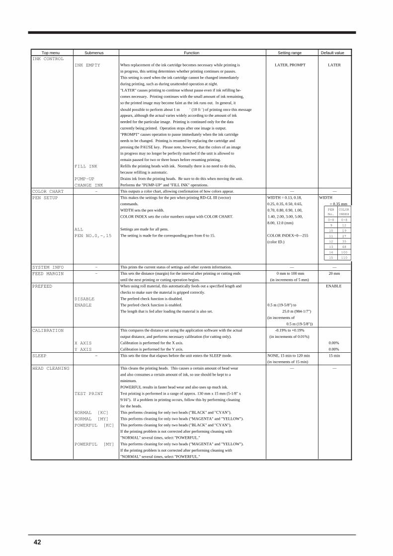
INK CONTROL
INK EMPTY When replacement of the ink cartridge becomes necessary while printing is LATER, PROMPT LATER
in progress, this setting determines whether printing continues or pauses.
This setting is used when the ink cartridge cannot be changed immediately
during printing, such as during unattended operation at night.
"LATER" causes printing to continue without pause even if ink refilling be-
comes necessary. Printing continues with the small amount of ink remaining,
so the printed image may become faint as the ink runs out. In general, it
should possible to perform about 1 m 2 (10 ft 2) of printing once this message
appears, although the actual varies widely according to the amount of ink
needed for the particular image. Printing is continued only for the data
currently being printed. Operation stops after one image is output.
"PROMPT" causes operation to pause immediately when the ink cartridge
needs to be changed. Printing is resumed by replacing the cartridge and
pressing the PAUSE key. Please note, however, that the colors of an image
in progress may no longer be perfectly matched if the unit is allowed to
remain paused for two or three hours before resuming printing.
FILL INK Refills the printing heads with ink. Normally there is no need to do this,
because refilling is automatic.
PUMP-UP Drains ink from the printing heads. Be sure to do this when moving the unit.
CHANGE INK Performs the "PUMP-UP" and "FILL INK" operations.
COLOR CHART — This outputs a color chart, allowing confirmation of how colors appear. — —
PEN SETUP This makes the settings for the pen when printing RD-GL III (vector) WIDTH = 0.13, 0.18, WIDTH
commands. 0.25, 0.35, 0.50, 0.65, = 0.35 mm
WIDTH sets the pen width. 0.70, 0.80, 0.90, 1.00,
COLOR INDEX sets the color numbers output with COLOR CHART. 1.40, 2.00, 3.00, 5.00,
8.00, 12.0 (mm)
ALL Settings are made for all pens.
PEN NO.0,—,15 The setting is made for the corresponding pen from 0 to 15. COLOR INDEX=0—255
(color ID.)
SYSTEM INFO — This prints the current status of settings and other system information. — —
FEED MARGIN — This sets the distance (margin) for the interval after printing or cutting ends 0 mm to 100 mm 20 mm
until the next printing or cutting operation begins. (in increments of 5 mm)
PREFEED When using roll material, this automatically feeds out a specified length and ENABLE
checks to make sure the material is gripped correctly.
DISABLE The prefeed check function is disabled.
ENABLE The prefeed check function is enabled. 0.5 m (19-5/8") to
The length that is fed after loading the material is also set. 25.0 m (984-1/7")
(in increments of
0.5 m (19-5/8"))
CALIBRATION This compares the distance set using the application software with the actual -0.19% to +0.19%
output distance, and performs necessary calibration (for cutting only). (in increments of 0.01%)
X AXIS Calibration is performed for the X axis. 0.00%
Y AXIS Calibration is performed for the Y axis. 0.00%
SLEEP — This sets the time that elapses before the unit enters the SLEEP mode. NONE, 15 min to 120 min 15 min
(in increments of 15 min)
HEAD CLEANING This cleans the printing heads. This causes a certain amount of head wear — —
and also consumes a certain amount of ink, so use should be kept to a
minimum.
POWERFUL results in faster head wear and also uses up much ink.
TEST PRINT Test printing is performed in a range of approx. 130 mm x 15 mm (5-1/8" x
9/16"). If a problem in printing occurs, follow this by performing cleaning
for the heads.
NORMAL [KC] This performs cleaning for only two heads ("BLACK" and "CYAN").
NORMAL [MY] This performs cleaning for only two heads ("MAGENTA" and "YELLOW").
POWERFUL [KC] This performs cleaning for only two heads ("BLACK" and "CYAN").
If the printing problem is not corrected after performing cleaning with
"NORMAL" several times, select "POWERFUL."
POWERFUL [MY] This performs cleaning for only two heads ("MAGENTA" and "YELLOW").
If the printing problem is not corrected after performing cleaning with
"NORMAL" several times, select "POWERFUL."
PEN COLOR
No. INDEX
0—8 0—8
9 12
10 19
11 27
12 35
13 68
14 100
15 110
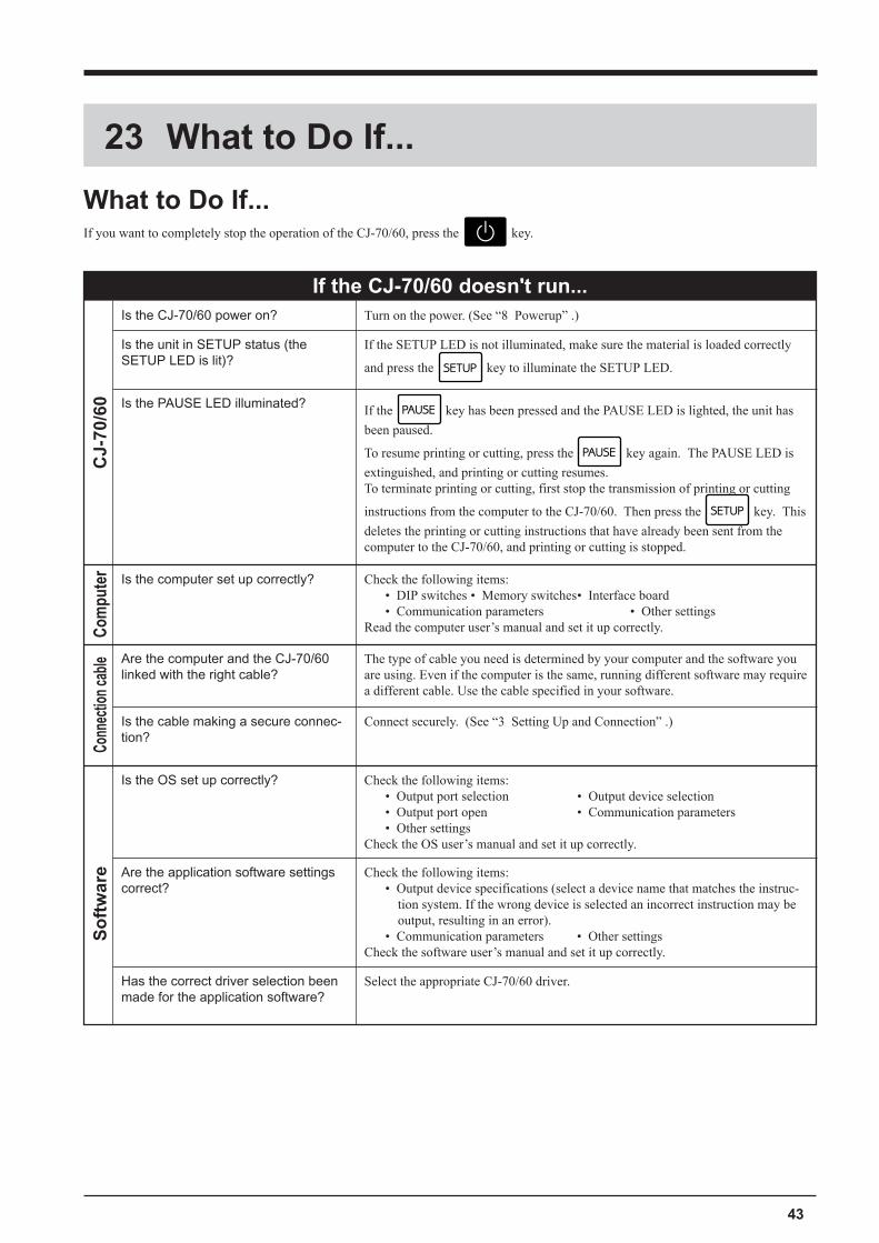
43
23 What to Do If...
What to Do If...If you want to completely stop the operation of the CJ-70/60, press the key.
Is the CJ-70/60 power on? Turn on the power. (See �8 Powerup� .)
Is the unit in SETUP status (theSETUP LED is lit)?
If the SETUP LED is not illuminated, make sure the material is loaded correctly
and press the key to illuminate the SETUP LED.
Is the PAUSE LED illuminated? If the key has been pressed and the PAUSE LED is lighted, the unit has
been paused.
To resume printing or cutting, press the key again. The PAUSE LED is
extinguished, and printing or cutting resumes.To terminate printing or cutting, first stop the transmission of printing or cutting
instructions from the computer to the CJ-70/60. Then press the key. This
deletes the printing or cutting instructions that have already been sent from thecomputer to the CJ-70/60, and printing or cutting is stopped.
CJ-
70/6
0
Is the computer set up correctly? Check the following items:� DIP switches � Memory switches� Interface board� Communication parameters � Other settings
Read the computer user�s manual and set it up correctly.Com
pute
r
If the CJ-70/60 doesn't run...
Are the computer and the CJ-70/60linked with the right cable?
The type of cable you need is determined by your computer and the software youare using. Even if the computer is the same, running different software may requirea different cable. Use the cable specified in your software.
Is the cable making a secure connec-tion?
Connect securely. (See �3 Setting Up and Connection� .)
Conn
ectio
n ca
ble
Is the OS set up correctly? Check the following items:� Output port selection � Output device selection� Output port open � Communication parameters� Other settings
Check the OS user�s manual and set it up correctly.
Are the application software settingscorrect?
Check the following items:� Output device specifications (select a device name that matches the instruc-
tion system. If the wrong device is selected an incorrect instruction may beoutput, resulting in an error).
� Communication parameters � Other settingsCheck the software user�s manual and set it up correctly.
Has the correct driver selection beenmade for the application software?
Select the appropriate CJ-70/60 driver.
So
ftw
are
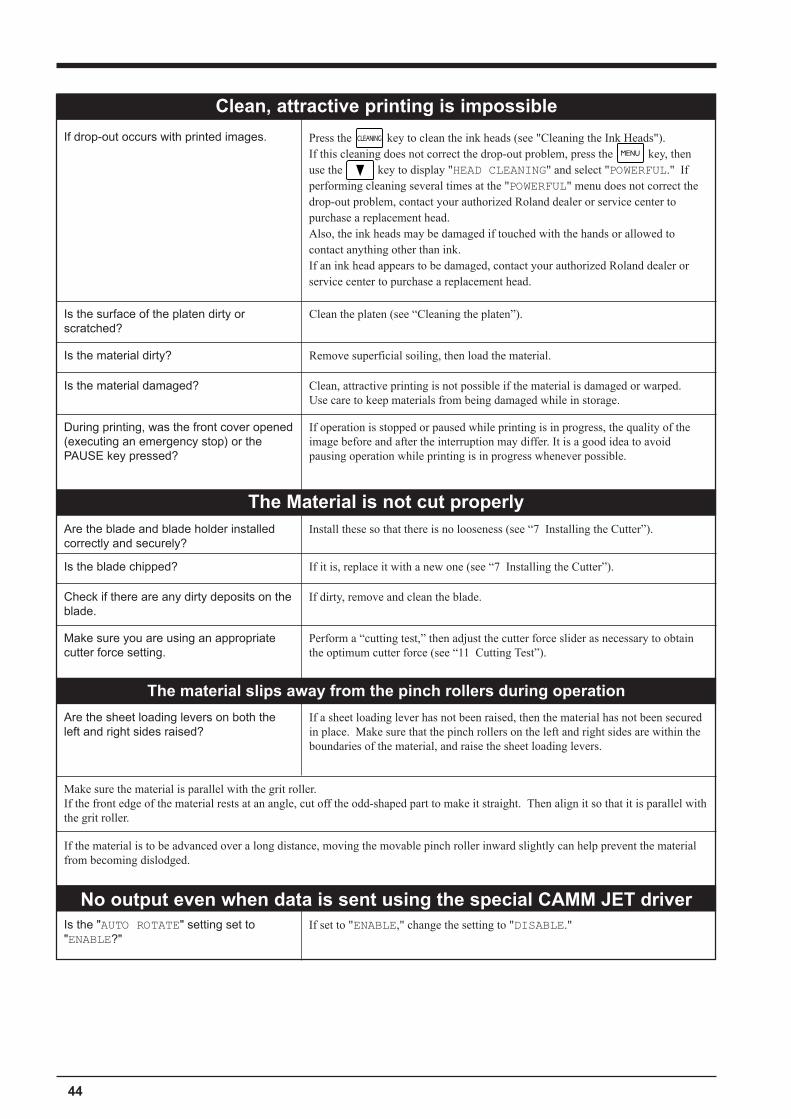
44
If drop-out occurs with printed images.
Clean, attractive printing is impossible
Is the surface of the platen dirty orscratched?
Clean the platen (see �Cleaning the platen�).
Is the material dirty? Remove superficial soiling, then load the material.
Clean, attractive printing is not possible if the material is damaged or warped.Use care to keep materials from being damaged while in storage.
Is the material damaged?
The Material is not cut properlyAre the blade and blade holder installedcorrectly and securely?
Install these so that there is no looseness (see �7 Installing the Cutter�).
Is the blade chipped? If it is, replace it with a new one (see �7 Installing the Cutter�).
Check if there are any dirty deposits on theblade.
If dirty, remove and clean the blade.
Make sure you are using an appropriatecutter force setting.
Perform a �cutting test,� then adjust the cutter force slider as necessary to obtainthe optimum cutter force (see �11 Cutting Test�).
The material slips away from the pinch rollers during operation
Are the sheet loading levers on both theleft and right sides raised?
If a sheet loading lever has not been raised, then the material has not been securedin place. Make sure that the pinch rollers on the left and right sides are within theboundaries of the material, and raise the sheet loading levers.
Make sure the material is parallel with the grit roller.If the front edge of the material rests at an angle, cut off the odd-shaped part to make it straight. Then align it so that it is parallel withthe grit roller.
If the material is to be advanced over a long distance, moving the movable pinch roller inward slightly can help prevent the materialfrom becoming dislodged.
No output even when data is sent using the special CAMM JET driverIf set to "ENABLE," change the setting to "DISABLE."
Press the key to clean the ink heads (see "Cleaning the Ink Heads").If this cleaning does not correct the drop-out problem, press the key, thenuse the key to display "HEAD CLEANING" and select "POWERFUL." Ifperforming cleaning several times at the "POWERFUL" menu does not correct thedrop-out problem, contact your authorized Roland dealer or service center topurchase a replacement head.Also, the ink heads may be damaged if touched with the hands or allowed tocontact anything other than ink.If an ink head appears to be damaged, contact your authorized Roland dealer orservice center to purchase a replacement head.
Is the "AUTO ROTATE" setting set to"ENABLE?"
If operation is stopped or paused while printing is in progress, the quality of theimage before and after the interruption may differ. It is a good idea to avoidpausing operation while printing is in progress whenever possible.
During printing, was the front cover opened(executing an emergency stop) or thePAUSE key pressed?
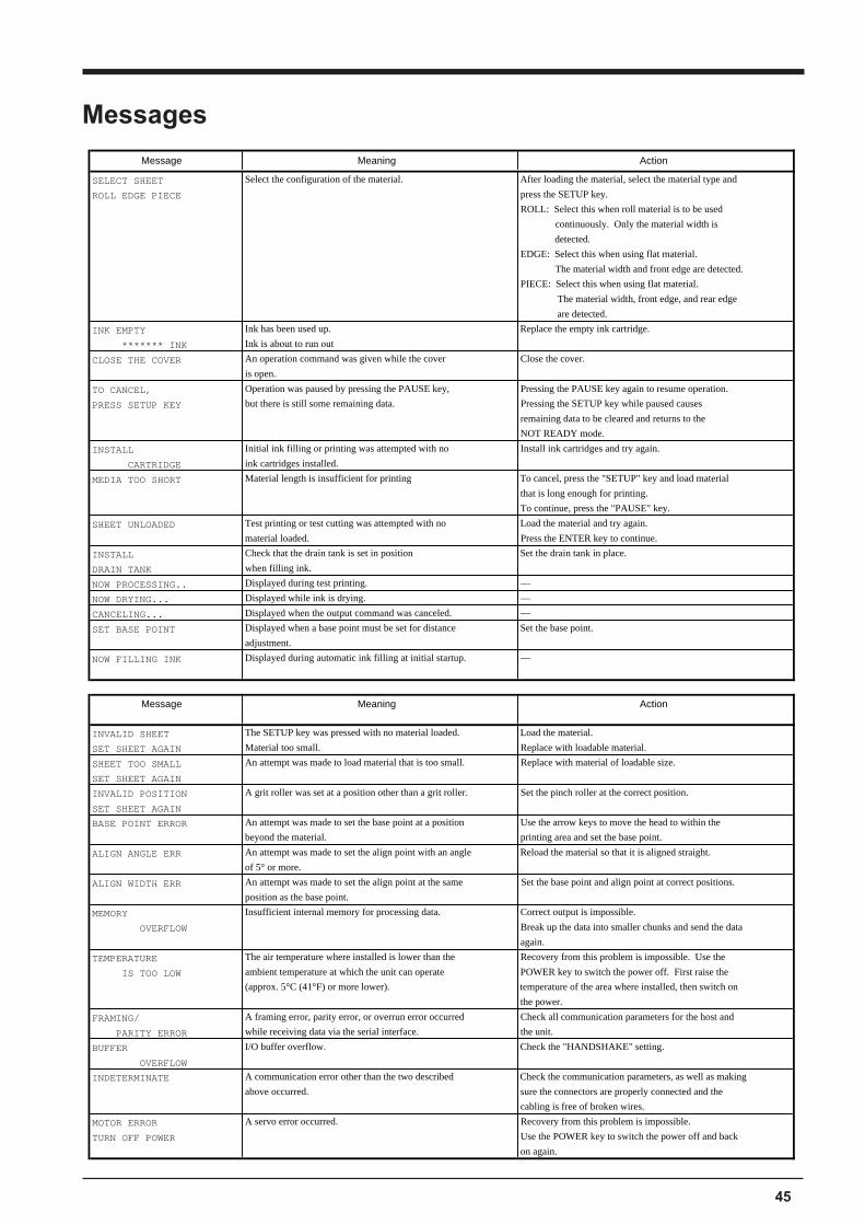
45
Message Meaning Action
SELECT SHEET Select the configuration of the material. After loading the material, select the material type and
ROLL EDGE PIECE press the SETUP key.
ROLL: Select this when roll material is to be used
continuously. Only the material width is
detected.
EDGE: Select this when using flat material.
The material width and front edge are detected.
PIECE: Select this when using flat material.
The material width, front edge, and rear edge
are detected.
INK EMPTY Ink has been used up. Replace the empty ink cartridge.
******* INK Ink is about to run out
CLOSE THE COVER An operation command was given while the cover Close the cover.
is open.
TO CANCEL, Operation was paused by pressing the PAUSE key, Pressing the PAUSE key again to resume operation.
PRESS SETUP KEY but there is still some remaining data. Pressing the SETUP key while paused causes
remaining data to be cleared and returns to the
NOT READY mode.
INSTALL Initial ink filling or printing was attempted with no Install ink cartridges and try again.
CARTRIDGE ink cartridges installed.
MEDIA TOO SHORT Material length is insufficient for printing To cancel, press the "SETUP" key and load material
that is long enough for printing.
To continue, press the "PAUSE" key.
SHEET UNLOADED Test printing or test cutting was attempted with no Load the material and try again.
material loaded. Press the ENTER key to continue.
INSTALL Check that the drain tank is set in position Set the drain tank in place.
DRAIN TANK when filling ink.
NOW PROCESSING.. Displayed during test printing. —
NOW DRYING... Displayed while ink is drying. —
CANCELING... Displayed when the output command was canceled. —
SET BASE POINT Displayed when a base point must be set for distance Set the base point.
adjustment.
NOW FILLING INK Displayed during automatic ink filling at initial startup. —
Message Meaning Action
INVALID SHEET The SETUP key was pressed with no material loaded. Load the material.
SET SHEET AGAIN Material too small. Replace with loadable material.
SHEET TOO SMALL An attempt was made to load material that is too small. Replace with material of loadable size.
SET SHEET AGAIN
INVALID POSITION A grit roller was set at a position other than a grit roller. Set the pinch roller at the correct position.
SET SHEET AGAIN
BASE POINT ERROR An attempt was made to set the base point at a position Use the arrow keys to move the head to within the
beyond the material. printing area and set the base point.
ALIGN ANGLE ERR An attempt was made to set the align point with an angle Reload the material so that it is aligned straight.
of 5° or more.
ALIGN WIDTH ERR An attempt was made to set the align point at the same Set the base point and align point at correct positions.
position as the base point.
MEMORY Insufficient internal memory for processing data. Correct output is impossible.
OVERFLOW Break up the data into smaller chunks and send the data
again.
TEMPERATURE The air temperature where installed is lower than the Recovery from this problem is impossible. Use the
IS TOO LOW ambient temperature at which the unit can operate POWER key to switch the power off. First raise the
(approx. 5°C (41°F) or more lower). temperature of the area where installed, then switch on
the power.
FRAMING/ A framing error, parity error, or overrun error occurred Check all communication parameters for the host and
PARITY ERROR while receiving data via the serial interface. the unit.
BUFFER I/O buffer overflow. Check the "HANDSHAKE" setting.
OVERFLOW
INDETERMINATE A communication error other than the two described Check the communication parameters, as well as making
above occurred. sure the connectors are properly connected and the
cabling is free of broken wires.
MOTOR ERROR A servo error occurred. Recovery from this problem is impossible.
TURN OFF POWER Use the POWER key to switch the power off and back
on again.
Messages
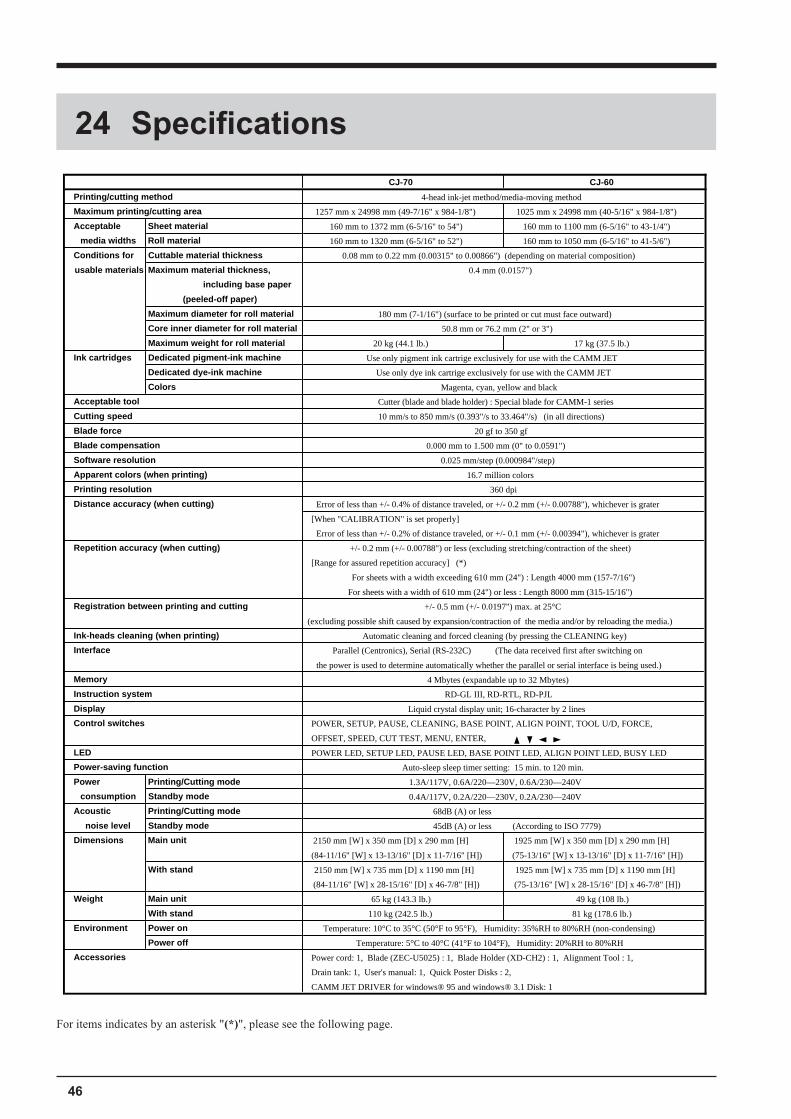
46
CJ-70 CJ-60
Printing/cutting method 4-head ink-jet method/media-moving method
Maximum printing/cutting area 1257 mm x 24998 mm (49-7/16" x 984-1/8") 1025 mm x 24998 mm (40-5/16" x 984-1/8")
Acceptable Sheet material 160 mm to 1372 mm (6-5/16" to 54") 160 mm to 1100 mm (6-5/16" to 43-1/4")
media widths Roll material 160 mm to 1320 mm (6-5/16" to 52") 160 mm to 1050 mm (6-5/16" to 41-5/6")
Conditions for Cuttable material thickness 0.08 mm to 0.22 mm (0.00315" to 0.00866") (depending on material composition)
usable materials Maximum material thickness, 0.4 mm (0.0157")
including base paper
(peeled-off paper)
Maximum diameter for roll material 180 mm (7-1/16") (surface to be printed or cut must face outward)
Core inner diameter for roll material 50.8 mm or 76.2 mm (2" or 3")
Maximum weight for roll material 20 kg (44.1 lb.) 17 kg (37.5 lb.)
Ink cartridges Dedicated pigment-ink machine Use only pigment ink cartrige exclusively for use with the CAMM JET
Dedicated dye-ink machine Use only dye ink cartrige exclusively for use with the CAMM JET
Colors Magenta, cyan, yellow and black
Acceptable tool Cutter (blade and blade holder) : Special blade for CAMM-1 series
Cutting speed 10 mm/s to 850 mm/s (0.393"/s to 33.464"/s) (in all directions)
Blade force 20 gf to 350 gf
Blade compensation 0.000 mm to 1.500 mm (0" to 0.0591")
Software resolution 0.025 mm/step (0.000984"/step)
Apparent colors (when printing) 16.7 million colors
Printing resolution 360 dpi
Distance accuracy (when cutting) Error of less than +/- 0.4% of distance traveled, or +/- 0.2 mm (+/- 0.00788"), whichever is grater
[When "CALIBRATION" is set properly]
Error of less than +/- 0.2% of distance traveled, or +/- 0.1 mm (+/- 0.00394"), whichever is grater
Repetition accuracy (when cutting) +/- 0.2 mm (+/- 0.00788") or less (excluding stretching/contraction of the sheet)
[Range for assured repetition accuracy] (*)
For sheets with a width exceeding 610 mm (24") : Length 4000 mm (157-7/16")
For sheets with a width of 610 mm (24") or less : Length 8000 mm (315-15/16")
Registration between printing and cutting +/- 0.5 mm (+/- 0.0197") max. at 25°C
(excluding possible shift caused by expansion/contraction of the media and/or by reloading the media.)
Ink-heads cleaning (when printing) Automatic cleaning and forced cleaning (by pressing the CLEANING key)
Interface Parallel (Centronics), Serial (RS-232C) (The data received first after switching on
the power is used to determine automatically whether the parallel or serial interface is being used.)
Memory 4 Mbytes (expandable up to 32 Mbytes)
Instruction system RD-GL III, RD-RTL, RD-PJL
Display Liquid crystal display unit; 16-character by 2 lines
Control switches POWER, SETUP, PAUSE, CLEANING, BASE POINT, ALIGN POINT, TOOL U/D, FORCE,
OFFSET, SPEED, CUT TEST, MENU, ENTER,
LED POWER LED, SETUP LED, PAUSE LED, BASE POINT LED, ALIGN POINT LED, BUSY LED
Power-saving function Auto-sleep sleep timer setting: 15 min. to 120 min.
Power Printing/Cutting mode 1.3A/117V, 0.6A/220—230V, 0.6A/230—240V
consumption Standby mode 0.4A/117V, 0.2A/220—230V, 0.2A/230—240V
Acoustic Printing/Cutting mode 68dB (A) or less
noise level Standby mode 45dB (A) or less (According to ISO 7779)
Dimensions Main unit 2150 mm [W] x 350 mm [D] x 290 mm [H] 1925 mm [W] x 350 mm [D] x 290 mm [H]
(84-11/16" [W] x 13-13/16" [D] x 11-7/16" [H]) (75-13/16" [W] x 13-13/16" [D] x 11-7/16" [H])
With stand 2150 mm [W] x 735 mm [D] x 1190 mm [H] 1925 mm [W] x 735 mm [D] x 1190 mm [H]
(84-11/16" [W] x 28-15/16" [D] x 46-7/8" [H]) (75-13/16" [W] x 28-15/16" [D] x 46-7/8" [H])
Weight Main unit 65 kg (143.3 lb.) 49 kg (108 lb.)
With stand 110 kg (242.5 lb.) 81 kg (178.6 lb.)
Environment Power on Temperature: 10°C to 35°C (50°F to 95°F), Humidity: 35%RH to 80%RH (non-condensing)
Power off Temperature: 5°C to 40°C (41°F to 104°F), Humidity: 20%RH to 80%RH
Accessories Power cord: 1, Blade (ZEC-U5025) : 1, Blade Holder (XD-CH2) : 1, Alignment Tool : 1,
Drain tank: 1, User's manual: 1, Quick Poster Disks : 2,
CAMM JET DRIVER for windows® 95 and windows® 3.1 Disk: 1
24 Specifications
For items indicates by an asterisk "(*)", please see the following page.
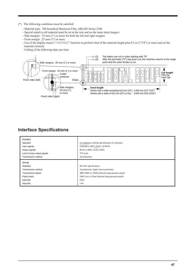
47
[Parallel]
Standard In compliance with the specifications of Centronics
Input signals STROBE (1 BIT), DATA (8 BITS)
Output signals BUSY (1 BIT), ACK (1 BIT)
Level of input output signals TTL level
Transmission method Asynchronous
[Serial]
Standard RS-232C specifications
Transmission method Asynchronous, duplex data transmission
Transmission speed 4800, 9600, or 19200 (selected using operation panel)
Parity check Odd, Even, or None (selected using operation panel)
Data bits 8 bits
Stop bits 1 bit
Interface Specifications
(*) The following conditions must be satisfied:
- Material type: 3M Scotchcal Mastercut Film, ARLON Series 2100- Special stand (a roll material must be set at the rear and on the inner sheet hanger)- Side margins: 25 mm (1") or more for both the left and right margins- Front margin: 25 mm (1") or more- Use of the display menu�s �PREFEED� function to perform feed of the material length plus 0.2 m (7-7/8") or more and set thematerial correctly
- Cutting of the following data one time
Origin
(1) The letters are cut in order starting with "R"(2) After the last letter ("P") has been cut, the machine returns to the origin point and the outer border is cut
Feed lengthSheets with a width exceeding 610 mm (24"): 4,000 mm (157-7/16")Sheets with a width of 610 mm (24") or less : 8,000 mm (315-15/16")
Cut lengthFills the hard clip
Front margin: 25 mm (1") or more
Side margins: 25 mm (1") or more
Side margins: 25 mm (1") or more
Pinch roller (left)
Pinch roller (right)
Cutter protector
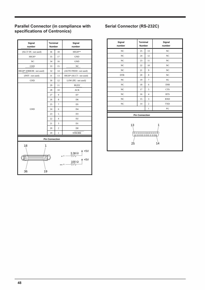
48
Parallel Connector (in compliance withspecifications of Centronics)
Serial Connector (RS-232C)
Signal Terminal Signal
number Number number
(SLCT IN : not used) 36 18 HIGH**
HIGH* 35 17 GND
NC 34 16 GND
GND 33 15 NC
HIGH* (ERROR : not used) 32 14 (AUTO FEED : not used)
(INIT : not used) 31 13 HIGH* (SLCT : not used)
GND 30 12 LOW (PE : not used)
29 11 BUSY
28 10 ACK
27 9 D7
26 8 D6
25 7 D5
GND 24 6 D4
23 5 D3
22 4 D2
21 3 D1
20 2 D0
19 1 STROBE
Pin Connection
1
19
18
36
3.3K+5V
=*
100+5V
=**
Signal Terminal Signal
number Number number
NC 25 13 NC
NC 24 12 NC
NC 23 11 NC
NC 22 10 NC
NC 21 9 NC
DTR 20 8 NC
NC 19 7 SG
NC 18 6 DSR
NC 17 5 CTS
NC 16 4 RTS
NC 15 3 RXD
NC 14 2 TXD
1 FG
Pin Connection
1
14
13
25
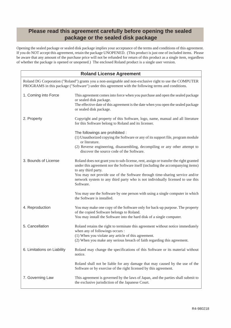
R4-980218
Please read this agreement carefully before opening the sealed package or the sealed disk package
Roland License Agreement
Roland DG Corporation ("Roland") grants you a non-assignable and non-exclusive right to use the COMPUTERPROGRAMS in this package ("Software") under this agreement with the following terms and conditions.
1. Coming into Force This agreement comes into force when you purchase and open the sealed packageor sealed disk package.The effective date of this agreement is the date when you open the sealed packageor sealed disk package.
2. Property Copyright and property of this Software, logo, name, manual and all literaturefor this Software belong to Roland and its licenser.
The followings are prohibited :(1) Unauthorized copying the Software or any of its support file, program module
or literature.(2) Reverse engineering, disassembling, decompiling or any other attempt to
discover the source code of the Software.
3. Bounds of License Roland does not grant you to sub-license, rent, assign or transfer the right grantedunder this agreement nor the Software itself (including the accompanying items)to any third party.You may not provide use of the Software through time-sharing service and/ornetwork system to any third party who is not individually licensed to use thisSoftware.
You may use the Software by one person with using a single computer in whichthe Software is installed.
4. Reproduction You may make one copy of the Software only for back-up purpose. The propertyof the copied Software belongs to Roland.You may install the Software into the hard disk of a single computer.
5. Cancellation Roland retains the right to terminate this agreement without notice immediatelywhen any of followings occurs :(1) When you violate any article of this agreement.(2) When you make any serious breach of faith regarding this agreement.
6. Limitations on Liability Roland may change the specifications of this Software or its material withoutnotice.
Roland shall not be liable for any damage that may caused by the use of theSoftware or by exercise of the right licensed by this agreement.
7. Governing Law This agreement is governed by the laws of Japan, and the parties shall submit tothe exclusive jurisdiction of the Japanese Court.
Opening the sealed package or sealed disk package implies your acceptance of the terms and conditions of this agreement.If you do NOT accept this agreement, retain the package UNOPENED. (This product is just one of included items. Pleasebe aware that any amount of the purchase price will not be refunded for return of this product as a single item, regardlessof whether the package is opened or unopened.) The enclosed Roland product is a single user version.