Embed Size (px)
Citation preview
1
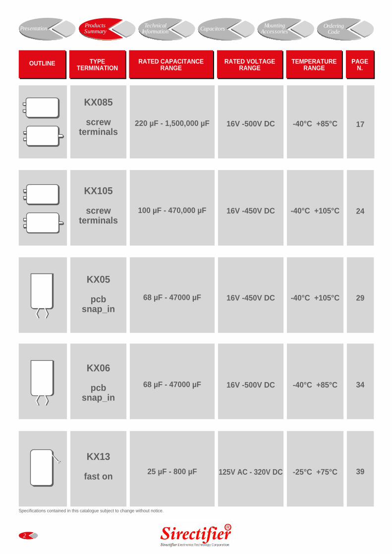
PRODUCTS SUMMARY
Products overview page 2KX085 KX105 screw terminal type page 3KX05 KX06 snap in terminal type page 4
TECHNICAL INFORMATION
Building an electrolytic capacitor page 5Electrical characteristics page 7Reliability page 10Useful life page 11Guidelines page 12Quality page 16
CAPACITORS
KX085 Screw type Specification page 17Standard ratings page 19
KX105 Screw type Specification page 24Standard ratings page 26
KX05 Screw type Specification page 29Standard ratings page 31
KX06 Screw type Specification page 34Standard ratings page 36
KX13 Screw type Specification page 39
MOUNTING ACCESSORIES
Ring clips, washers, hex nuts page 40Mounting hardware page 41
ORDERING CODE
Case size table page 40Part number system page 42Capacitors weight table page 43
INDEX
2
OUTLINE TYPETERMINATION
RATED CAPACITANCERANGE
RATED VOLTAGERANGE
PAGEN.
TEMPERATURERANGE
KX085
screwterminals
KX105
screwterminals
KX05
pcbsnap_in
KX06
pcbsnap_in
KX13
fast on
220 µF - 1,500,000 µF
100 µF - 470,000 µF
68 µF - 47000 µF
68 µF - 47000 µF
25 µF - 800 µF
16V -500V DC
16V -450V DC
16V -450V DC
16V -500V DC
125V AC - 320V DC
-40°C +85°C
-40°C +105°C
-40°C +105°C
-40°C +85°C
-25°C +75°C
17
24
29
34
39
Specifications contained in this catalogue subject to change without notice.
Presentation ProductsSummary Capacitors Mounting
AccessoriesOrdering
CodeTechnical
Information
KX105
KX085
3
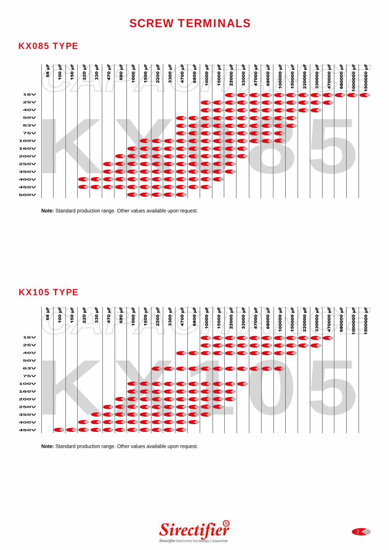
SCREW TERMINALS
16V
25V
40V
50V
63V
75V
100V
160V
200V
250V
350V
400V
450V
500V
16V
25V
40V
50V
63V
75V
100V
160V
200V
250V
350V
400V
450V
KX085 TYPE
KX105 TYPE
Note: Standard production range. Other values available upon request.
Note: Standard production range. Other values available upon request.
KX06
KX05
4
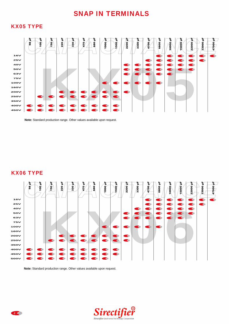
SNAP IN TERMINALS
16V
25V
40V
50V
63V
75V
100V
160V
200V
250V
350V
400V
450V
16V
25V
40V
50V
63V
75V
100V
160V
200V
250V
350V
400V
450V
500V
KX05 TYPE
KX06 TYPE
Note: Standard production range. Other values available upon request.
Note: Standard production range. Other values available upon request.
5
TechnicalInformation Presentation Capacitors Mounting
AccessoriesOrdering
CodeProductsSummary
APPLICATIONS
A capacitor is an electrical component that stores a quantity of electrical charge defined with a linear relationship as:
Q = C x V
where: Q = electrical charge [Coulomb] C = Capacitance [Farad] V = Voltage [Volt]
Usually values are indicated in a smaller unit called micro Farad [µF] that is one million times smaller.An aluminium electrolytic capacitor is composed of one anode of aluminium foil (or one aluminium foil anode) having adielectric oxidation on its surface, with semiconductor characteristics to prevent the current flow in one direction, and anotheraluminium foil cathode. There is also an electrolyte impregnated paper layer positioned between the anode and the cathodein order to avoid short circuits. Both the aluminium foils have been etched to obtain active surfaces, increasing their effectivearea. Aluminium tabs are then connected to the two foils to act as terminals. When in use the impregnated section is thenclosed inside an suitable case and sealed with a deck.The matching of thin dielectric and a large surface area allows to create capacitors with exceptional high capacitance pervolume.
European (CECC) and International standards (IEC) have classified the capacitors in two categories. Electrolytic capacitorsfor high reliability applications (Long Life Grade): in addition of the possible over anodization (the difference between formingvoltage and operating voltage) must generally satisfy high endurance requirements and a careful selection on materials isneeded.Such efforts are not required for capacitors standard version used for less severe reliability (General Purpose Grade).
The whole manufacturing process requested to build a Sirectifier electrolytic capacitor could be reasonably split into the following phases:
* Etching* Winding* Impregnation* Sealing* Ageing* Production Inspections
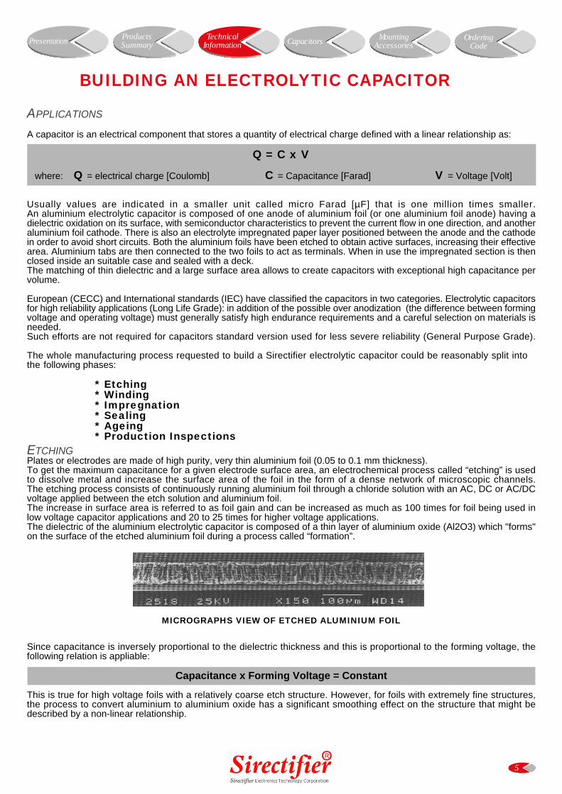
ETCHINGPlates or electrodes are made of high purity, very thin aluminium foil (0.05 to 0.1 mm thickness).To get the maximum capacitance for a given electrode surface area, an electrochemical process called “etching” is usedto dissolve metal and increase the surface area of the foil in the form of a dense network of microscopic channels.The etching process consists of continuously running aluminium foil through a chloride solution with an AC, DC or AC/DCvoltage applied between the etch solution and aluminium foil.The increase in surface area is referred to as foil gain and can be increased as much as 100 times for foil being used inlow voltage capacitor applications and 20 to 25 times for higher voltage applications.The dielectric of the aluminium electrolytic capacitor is composed of a thin layer of aluminium oxide (Al2O3) which "forms"on the surface of the etched aluminium foil during a process called “formation”.
MICROGRAPHS VIEW OF ETCHED ALUMINIUM FOIL
Since capacitance is inversely proportional to the dielectric thickness and this is proportional to the forming voltage, thefollowing relation is appliable:
Capacitance x Forming Voltage = Constant
This is true for high voltage foils with a relatively coarse etch structure. However, for foils with extremely fine structures,the process to convert aluminium to aluminium oxide has a significant smoothing effect on the structure that might bedescribed by a non-linear relationship.
BUILDING AN ELECTROLYTIC CAPACITOR
6
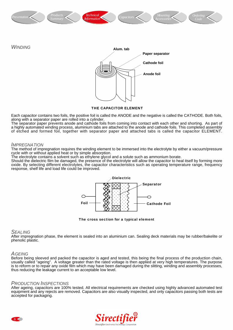
Alum. tabPaper separator
Cathode foil
Anode foil
Separator
Cathode FoilFoil
Dielectric
TechnicalInformation Presentation Capacitors Mounting
AccessoriesOrdering
CodeProductsSummary
WINDING
THE CAPACITOR ELEMENT
Each capacitor contains two foils, the positive foil is called the ANODE and the negative is called the CATHODE. Both foils,along with a separator paper are rolled into a cylinder.The separator paper prevents anode and cathode foils from coming into contact with each other and shorting. As part ofa highly automated winding process, aluminium tabs are attached to the anode and cathode foils. This completed assemblyof etched and formed foil, together with separator paper and attached tabs is called the capacitor ELEMENT.
IMPREGNATIONThe method of impregnation requires the winding element to be immersed into the electrolyte by either a vacuum/pressurecycle with or without applied heat or by simple absorption.The electrolyte contains a solvent such as ethylene glycol and a solute such as ammonium borate.Should the dielectric film be damaged, the presence of the electrolyte will allow the capacitor to heal itself by forming moreoxide. By selecting different electrolytes, the capacitor characteristics such as operating temperature range, frequencyresponse, shelf life and load life could be improved.
The cross section for a typical element
SEALINGAfter impregnation phase, the element is sealed into an aluminium can. Sealing deck materials may be rubber/bakelite orphenolic plastic.
AGEINGBefore being sleeved and packed the capacitor is aged and tested, this being the final process of the production chain,usually called "ageing". A voltage greater than the rated voltage is then applied at very high temperatures. The purposeis to reform or to repair any oxide film which may have been damaged during the slitting, winding and assembly processes,thus reducing the leakage current to an acceptable low level.
PRODUCTION INSPECTIONSAfter ageing, capacitors are 100% tested. All electrical requirements are checked using highly advanced automated testequipment and any rejects are removed. Capacitors are also visually inspected, and only capacitors passing both tests areaccepted for packaging.
7
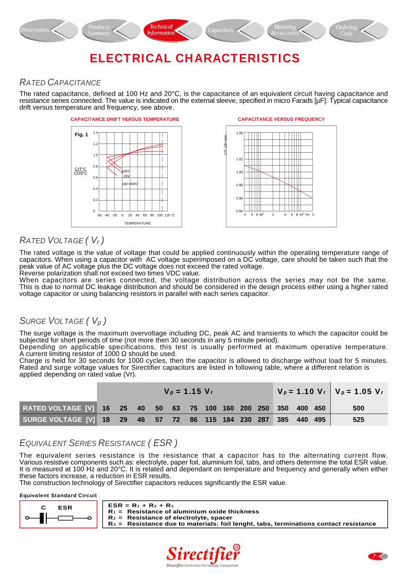
ELECTRICAL CHARACTERISTICS
Vp = 1.15 Vr Vp = 1.10 Vr
Equivalent Standard Circuit
ESR = R1 + R2 + R3
R1 = Resistance of aluminium oxide thicknessR2 = Resistance of electrolyte, spacerR3 = Resistance due to materials: foil lenght, tabs, terminations contact resistance
ESRC
RATED VOLTAGE [V] 16 25 40 50 63 75 100 160 200 250 350 400 450 500
SURGE VOLTAGE [V] 18 29 46 57 72 86 115 184 230 287 385 440 495 525
CAPACITANCE VERSUS FREQUENCY
Vp = 1.05 Vr
CAPACITANCE DRIFT VERSUS TEMPERATURE
1.4
1.2
1.0
0.8
0.6
0.4
0.2
0-60 -40 -20 0 20 40 60 80 100 120 °C
TEMPERATURE
CrT°CCr20°C
100V
25V
160÷450V
Fig. 1
RATED CAPACITANCE
The rated capacitance, defined at 100 Hz and 20°C, is the capacitance of an equivalent circuit having capacitance andresistance series connected. The value is indicated on the external sleeve, specified in micro Farads [µF]. Typical capacitancedrift versus temperature and frequency, see above.
RATED VOLTAGE ( Vr )The rated voltage is the value of voltage that could be applied continuously within the operating temperature range ofcapacitors. When using a capacitor with AC voltage superimposed on a DC voltage, care should be taken such that thepeak value of AC voltage plus the DC voltage does not exceed the rated voltage.Reverse polarization shall not exceed two times VDC value.When capacitors are series connected, the voltage distribution across the series may not be the same.This is due to normal DC leakage distribution and should be considered in the design process either using a higher ratedvoltage capacitor or using balancing resistors in parallel with each series capacitor.
SURGE VOLTAGE ( Vp )The surge voltage is the maximum overvoltage including DC, peak AC and transients to which the capacitor could besubjected for short periods of time (not more then 30 seconds in any 5 minute period).Depending on applicable specifications, this test is usually performed at maximum operative temperature.A current limiting resistor of 1000 Ω should be used.Charge is held for 30 seconds for 1000 cycles, then the capacitor is allowed to discharge without load for 5 minutes.Rated and surge voltage values for Sirectifier capacitors are listed in following table, where a different relation is applied depending on rated value (Vr).
EQUIVALENT SERIES RESISTANCE ( ESR )The equivalent series resistance is the resistance that a capacitor has to the alternating current flow.Various resistive components such as: electrolyte, paper foil, aluminium foil, tabs, and others determine the total ESR value.It is measured at 100 Hz and 20°C. It is related and dependant on temperature and frequency and generally when eitherthese factors increase, a reduction in ESR results.The construction technology of Sirectifier capacitors reduces significantly the ESR value.
C/C
100
rat
io
4 6 8 102 2 4 6 8 Hz103 20.94
0.96
0.98
1.00
1.02
1.06
TechnicalInformation Presentation Capacitors Mounting
AccessoriesOrdering
CodeProductsSummary
8
IL DRIFT VERSUS TIME
0 5 10 15 20
TIME (mn)
LEAKAGECURRENT
Fig. 2
IL DRIFT VERSUS TEMPERATURE
5 15 25 35 45 55 65 75 85 °C
TIME (mn)
LEAKAGECURRENT
Fig. 3
tg δ DRIFT VERSUS FREQUENCYLOW VOLTAGE (² 100 Vr d.c.)
101 5 102 5 103 5 104
FREQUENCY (Hz)
tan δ
Fig. 4101
5
100
5
10-1
5
10-2
+20°C
+85°C
-40°C
tg δ DRIFT VERSUS FREQUENCYHIGH VOLTAGE (> 100 Vr d.c.)
101 5 102 5 103 5 104
FREQUENCY (Hz)
tan δ
Fig. 5101
5
100
5
10-1
5
10-2
+20°C
+85°C
-40°C
TechnicalInformation Presentation Capacitors Mounting
AccessoriesOrdering
CodeProductsSummary
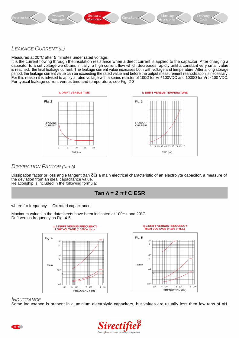
LEAKAGE CURRENT (IL)
Measured at 20°C after 5 minutes under rated voltage.It is the current flowing through the insulation resistance when a direct current is applied to the capacitor. After charging acapacitor to a set voltage we obtain, initially, a high current flow which decreases rapidly until a constant very small valueis reached, the final leakage current. The leakage current value increases both with voltage and temperature. After a long storageperiod, the leakage current value can be exceeding the rated value and before the output measurement reanodization is necessary.For this reason it is advised to apply a rated voltage with a series resistor of 100Ω for Vr ²100VDC and 1000Ω for Vr > 100 VDC.For typical leakage current versus time and temperature, see Fig. 2-3.
DISSIPATION FACTOR (tan δ)
Dissipation factor or loss angle tangent (tan δ) is a main electrical characteristic of an electrolyte capacitor, a measure ofthe deviation from an ideal capacitance value.Relationship is included in the following formula:
Tan δ = 2 π f C ESR
where f = frequency C= rated capacitance
Maximum values in the datasheets have been indicated at 100Hz and 20°C.Drift versus frequency as Fig. 4-5.
INDUCTANCESome inductance is present in aluminium electrolytic capacitors, but values are usually less then few tens of nH.
Z DRIFT VERSUS FREQUENCYLOW VOLTAGE (² 100 Vr d.c.)
101 4 102 4 103 4 104 4 105 4 105
FREQUENCY (Hz)
IMP
ED
EN
CE
(Ω
)
Fig. 6102
10
1
10-1
10-2
10-3
-40°C
+20°C
+85°C
Z DRIFT VERSUS FREQUENCYHIGH VOLTAGE (> 100 Vr d.c.)
101 4 102 4 103 4 104 4 105 4 105
FREQUENCY (Hz)
IMP
ED
EN
CE
(Ω
)
Fig. 7102
10
1
10-1
10-2
10-3
-40°C
+20°C
+85°C
TechnicalInformation Presentation Capacitors Mounting
AccessoriesOrdering
CodeProductsSummary
9
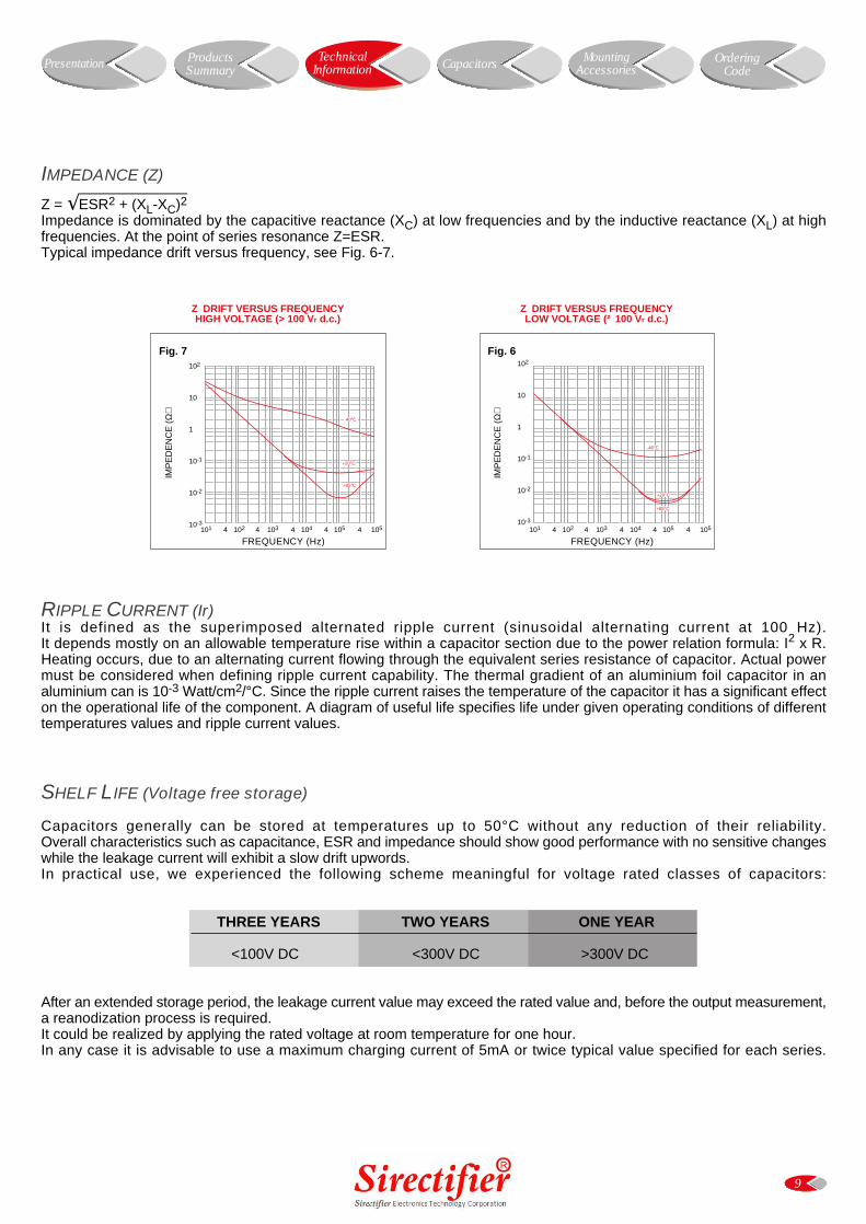
IMPEDANCE (Z)
Z = ESR2 + (XL-XC)2Impedance is dominated by the capacitive reactance (XC) at low frequencies and by the inductive reactance (XL) at highfrequencies. At the point of series resonance Z=ESR.Typical impedance drift versus frequency, see Fig. 6-7.
RIPPLE CURRENT (Ir)It is defined as the superimposed alternated ripple current (sinusoidal alternating current at 100 Hz).It depends mostly on an allowable temperature rise within a capacitor section due to the power relation formula: I2 x R.Heating occurs, due to an alternating current flowing through the equivalent series resistance of capacitor. Actual powermust be considered when defining ripple current capability. The thermal gradient of an aluminium foil capacitor in analuminium can is 10-3 Watt/cm2/°C. Since the ripple current raises the temperature of the capacitor it has a significant effecton the operational life of the component. A diagram of useful life specifies life under given operating conditions of differenttemperatures values and ripple current values.
SHELF LIFE (Voltage free storage)
Capacitors generally can be stored at temperatures up to 50°C without any reduction of their reliability.Overall characteristics such as capacitance, ESR and impedance should show good performance with no sensitive changeswhile the leakage current will exhibit a slow drift upwords.In practical use, we experienced the following scheme meaningful for voltage rated classes of capacitors:
THREE YEARS TWO YEARS ONE YEAR
<100V DC <300V DC >300V DC
After an extended storage period, the leakage current value may exceed the rated value and, before the output measurement,a reanodization process is required.It could be realized by applying the rated voltage at room temperature for one hour.In any case it is advisable to use a maximum charging current of 5mA or twice typical value specified for each series.
10
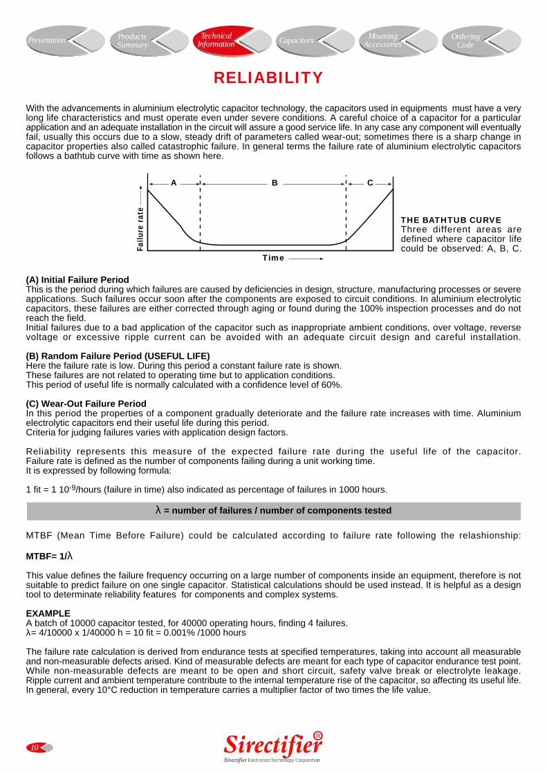
RELIABILITY
Time
Failu
re r
ate
A B C
THE BATHTUB CURVEThree different areas aredefined where capacitor lifecould be observed: A, B, C.
TechnicalInformation Presentation Capacitors Mounting
AccessoriesOrdering
CodeProductsSummary
With the advancements in aluminium electrolytic capacitor technology, the capacitors used in equipments must have a verylong life characteristics and must operate even under severe conditions. A careful choice of a capacitor for a particularapplication and an adequate installation in the circuit will assure a good service life. In any case any component will eventuallyfail, usually this occurs due to a slow, steady drift of parameters called wear-out; sometimes there is a sharp change incapacitor properties also called catastrophic failure. In general terms the failure rate of aluminium electrolytic capacitorsfollows a bathtub curve with time as shown here.
(A) Initial Failure PeriodThis is the period during which failures are caused by deficiencies in design, structure, manufacturing processes or severeapplications. Such failures occur soon after the components are exposed to circuit conditions. In aluminium electrolyticcapacitors, these failures are either corrected through aging or found during the 100% inspection processes and do notreach the field.Initial failures due to a bad application of the capacitor such as inappropriate ambient conditions, over voltage, reversevoltage or excessive ripple current can be avoided with an adequate circuit design and careful installation.
(B) Random Failure Period (USEFUL LIFE)Here the failure rate is low. During this period a constant failure rate is shown.These failures are not related to operating time but to application conditions.This period of useful life is normally calculated with a confidence level of 60%.
(C) Wear-Out Failure PeriodIn this period the properties of a component gradually deteriorate and the failure rate increases with time. Aluminiumelectrolytic capacitors end their useful life during this period.Criteria for judging failures varies with application design factors.
Reliability represents this measure of the expected failure rate during the useful life of the capacitor.Failure rate is defined as the number of components failing during a unit working time.It is expressed by following formula:
1 fit = 1 10-9/hours (failure in time) also indicated as percentage of failures in 1000 hours.
λ = number of failures / number of components tested
MTBF (Mean Time Before Failure) could be calculated according to failure rate following the relashionship:
MTBF= 1/λ
This value defines the failure frequency occurring on a large number of components inside an equipment, therefore is notsuitable to predict failure on one single capacitor. Statistical calculations should be used instead. It is helpful as a designtool to determinate reliability features for components and complex systems.
EXAMPLEA batch of 10000 capacitor tested, for 40000 operating hours, finding 4 failures.λ= 4/10000 x 1/40000 h = 10 fit = 0.001% /1000 hours
The failure rate calculation is derived from endurance tests at specified temperatures, taking into account all measurableand non-measurable defects arised. Kind of measurable defects are meant for each type of capacitor endurance test point.While non-measurable defects are meant to be open and short circuit, safety valve break or electrolyte leakage.Ripple current and ambient temperature contribute to the internal temperature rise of the capacitor, so affecting its useful life.In general, every 10°C reduction in temperature carries a multiplier factor of two times the life value.
11
USEFUL LIFE
The typical useful life represents a period of time until the end of life of the capacitor. The end is caused by different incidents(or different failure modes) such as the following:
MECHANICAL FAILURESoperation of safety vent due to overpressure, splitting of PVC sleeve and damaged insulation, unusable terminals, externalshort circuiting of terminals due to spilling of electrolyte.
OVER FAILURESwhen a short or open circuit occurs.
ELECTRICAL CHARACTERISTICS FAILURESIn a group of capacitors considered to have reached the end when 3% of them have failed, useful life is influenced byfollowing failure criteria:
a) ESR > 3 times initial valueb) impedance > 3 times initial valuec) capacitance value change of greater than 50%d) leakage current over initial limit.
In some cases, it is possible that even larger values of the above indicated could be applied without leading to failure, butgenerally capacitors tested in the laboratory at Sirectifier show standard behaviour around these limits.Obviously, when operating at lower voltages together with moderate temperature as well as lower values of current, thefinal life expectation should be better.When an adequate cooling system has been provided, the overall performance is substantially better and the life of thecapacitor is improved.
In normal conditions, statistics are produced after extensive endurance tests compliant to standard specifications. Dependingof the type of capacitor, endurance tests have been undertaken over different lengths of time using capacitors coming fromproduction batches. Data is collected and results summarized, so we have generated wide information displayed graphicallyfor each model, which can be seen on each product datasheet.The useful lifetime regarding the ambient temperature is given by following practical formula:
For ÆT ² 10°C
USEFUL LIFETIME = LOPMAX x 1.072 95-(Ta-ÆT)
For ÆT >10°C
USEFUL LIFETIME = LOPMAX x 1.072 95-(Ta-ÆT) x 1.12 -(ÆT-10)
Where:USEFUL LIFETIME expressed in hoursLOPMAX = Lifetime at max rated operating temperature (eg.: 10,000 hs at 85°C)Ta = Actual operating temperature (°C)ÆT = difference from capacitor temperature and ambient temperature
NOTEApplicable temperature range is the temperature depending on the capacitor type characteristics, usually situated in theoperating range of -40°C to +85°C or 105°C . Typically, each 10°C step carries a reduction factor of 2 times the lifetime value.
Useful life is also determined by ripple current.It is advisable not to apply a ripple current exceeding the max ripple current allowed as this will shorten capacitor life andmay result in opening of the vent or catastrophic failure.It often happens that heating due to ripple current is even more severe than ambient temperature stress.
TechnicalInformation Presentation Capacitors Mounting
AccessoriesOrdering
CodeProductsSummary
12
GUIDELINES FOR ALUMINIUM ELECTROLYTIC CAPACITORS
• POLARITY • SOLDERING• CHARGE - DISCHARGE APPLICATIONS • CLEANING• INSULATION • STORAGE• OPERATING TEMPERATURE • SAFETY• CLIMATIC CONDITIONS • BALANCING RESISTORS• MECHANICAL STRESS • FLAMMABILITY
• POLARITYIn DC applications polarity is required; if polarity is reversed, the circuit life will be shortened or the capacitor may bedamaged. Generally, an intermittent reverse voltage of 1V DC is allowed.If during operation, it is possible that polarity could be reversed or unknown, extensive use of a bipolar capacitor is required.
• CHARGE - DISCHARGE APPLICATIONS Sirectifier aluminium electrolytic capacitors are suitable for circuits in which a charge and discharge cycle is requested. Thefrequent cycles due to a charge or discharge operation could take some drop of capacitance value. In general one millionof switching with rated voltage one cycle for second a time costant of 0.1 carries an overall capacitance decrease less then 10%.
• INSULATIONIn general all aluminium electrolytic capacitors are covered with a PVC sleeve, that is also used for marking. The aluminiumcan is not insulated from the cathode, so when the internal element needs to be electrically insulated from the can, capacitorsspecially designed for insulation requirements should be used.
• OPERATING TEMPERATUREA capacitor should be chosen with a maximum specified temperature greater than the operating temperature of the application;this will increase the capacitor useful lifetime.
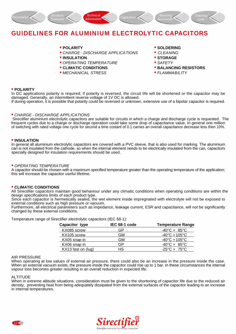
• CLIMATIC CONDITIONSAll Sirectifier capacitors maintain good behaviour under any climatic conditions when operating conditions are within thedesign specifications limits of each product type.Since each capacitor is hermetically sealed, the wet element inside impregnated with electrolyte will not be exposed toexternal conditions such as high pressure or vacuum.Furthermore, all electrical parameters such as impedance, leakage current, ESR and capacitance, will not be significantlychanged by these external conditions.
Temperature range of Sirectifier electrolytic capacitors (IEC 68-1):Capacitor type IEC 68-1 code Temperature Range
KX085 screw GP -40°C + 85°CKX105 screw GM -40°C +105°CKX05 snap in GM -40°C +105°CKX06 snap in GP -40°C + 85°CKX13 fast on (lug) HS -25°C + 75°C
AIR PRESSUREWhen operating at low values of external air pressure, there could also be an increase in the pressure inside the case.When an external vacuum exists, the pressure inside the capacitor could rise up to 1 bar. In these circumstances the internalvapour loss becomes greater resulting in an overall reduction in expected life.
ALTITUDEWhen in extreme altitude situations, consideration must be given to the shortening of capacitor life due to the reduced airdensity, preventing heat from being adequately dissipated from the external surfaces of the capacitor leading to an increasein internal temperatures.
TechnicalInformation Presentation Capacitors Mounting
AccessoriesOrdering
CodeProductsSummary
13
• MECHANICAL STRESSIf excessive force is applied to terminations, they may break or their connections with the inside element may be badlyaffected. The distance between terminations holes on the circuit board should be the same as the spacing betweenterminations on the capacitor.
SCREW TERMINAL - Sirectifier KX085/KX105 typeExcessive torque force applied in tightening the screws into terminals will result in stripping the threads and possibly increasingthe contact resistance. On the other hand, if screws are not enough tightened enough, the high contact resistance will causelocalized heating at terminals plus an early failure of the capacitor.
SNAP IN - Sirectifier KX05/KX06 typeImproper insertion into the circuit boards may break the terminals or impair their electrical connections with the internalelements. When provided, blank terminals of a multi-terminal capacitor should be considered to be at the same potentialas the electrolyte, or cathode, and should therefore be isolated from the circuit.
APPLICATION OF TORQUE TO ALUMINIUM THREADSPlease note the max appliable torque strength to KX085 and KX105 capacitors:With thread stud M5 = 2NmWith thread stud M12 = 4NmScrew torque strength for hex nuts M8 = 4NmScrew torque strength for hex nuts M12 = 10Nm
• SOLDERINGIncorrect soldering may shrink or break the capacitor sleeve. Please read the following information carefully.• When soldering a printed circuit board (PCB), the soldering temperature should not be excessive while time taken should
be short. Otherwise it could have adverse effects on the electrical characteristics and insulating sleeves.• During the soldering process, the sleeve may melt or break if it gets in contact with circuit board traces. Try to avoid this
problem and do not locate circuit board traces under capacitor body.• The sleeves may be melted by solder which migrates up through terminations holes in the circuit board.• When soldering adjacent components to the capacitor, preheated lead wires or terminals may tear the capacitor sleeve
if they come in contact with it. Therefore, capacitors are to be mounted carefully so that adjacent components terminationsdo not come into contact, particularly when mounting on through-hole circuit boards.
• CLEANINGAluminium can be aggressively attacked by halide ions, particularly by chloride ions. Even small amounts of chloride ionsinside the capacitor will cause corrosion which contributes to rapid capacitance drop and venting. Therefore, the preventionof chloride contamination is the most important check point for quality control in production. Solvent proof capacitors arerequired when chlorinated hydrocarbons are used for cleaning. If aluminium electrolytic capacitors without the solvent-proofconstruction are present on the circuit board, alcohol based solvents are recommended for cleaning.In this case, solvents such as methanol, ethanol, propanol and isopropanol should be used. Normal tests show that anydetrimental effect is eliminated. An alkaline detergent may damage the aluminium metal and marking.Aqueous cleaning methods in conjunction with saponification are commonly used. However it is advisable to dry immediatelywith hot air, which is best achieved at 85°C for few minutes.
• STORAGEAfter having a capacitor exposed to high temperatures such as direct sunlight or heating elements, the capacitor life maybe adversely affected. Also when capacitors have been stored under humid conditions for a long period of time, humiditywill cause terminals to oxidize. Therefore it is highly recommended they should be stored at room temperature, in a dryplace, out of direct sunlight.A voltage treatment process should be applied after some years storage period.When capacitors have been stored above room temperature, the anode foil may react with the electrolyte causing increasedleakage current values. Application of normal voltages to these capacitors may result in higher leakage current values, butin most cases, they will return to normal levels in short time.However on occasion it is possible that a certain amount of gas will be generated which might cause the safety vent to open.Capacitors that have been stored for long time should be subjected to a voltage reforming process which will regenerateinternal dielectric layers.
• SAFETYWhen an escape of electrolyte has occurred, wash the affected area with hot water. Use rubber gloves to avoid skin contact.Any contact with eyes should be immediately irrigated with water and medical advise is sought.Sirectifier electrolyte blends do not contain materials currently listed as carcinogetic or mutagenic such as polychlrolinatedbiphenyls (PCB) or dimethylformamide (DMF). No Butyrolactone used as solvent.Under exposure to electrolyte skin could become dry. Other irritations or effects may be caused to the mucous membranesparticularly eyes, where conjunctivitis may result.
TechnicalInformation Presentation Capacitors Mounting
AccessoriesOrdering
CodeProductsSummary
14
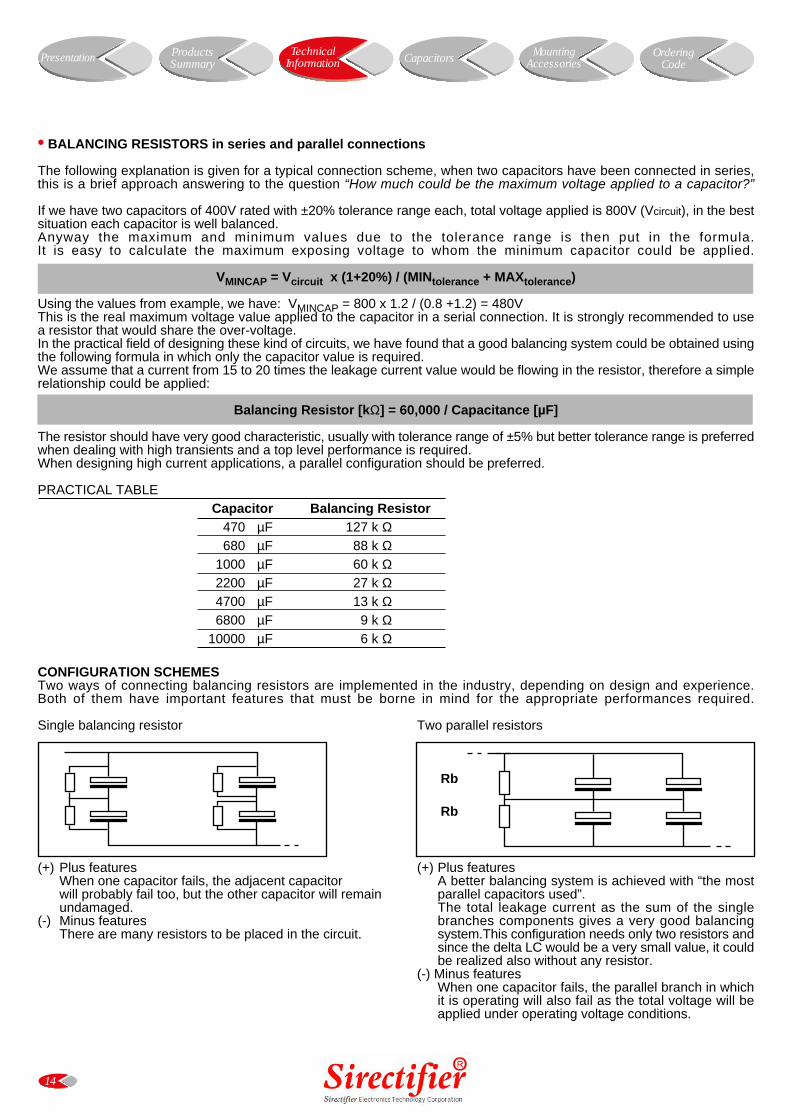
• BALANCING RESISTORS in series and parallel connections
The following explanation is given for a typical connection scheme, when two capacitors have been connected in series,this is a brief approach answering to the question “How much could be the maximum voltage applied to a capacitor?”
If we have two capacitors of 400V rated with ±20% tolerance range each, total voltage applied is 800V (Vcircuit), in the bestsituation each capacitor is well balanced.Anyway the maximum and minimum values due to the tolerance range is then put in the formula.It is easy to calculate the maximum exposing voltage to whom the minimum capacitor could be applied.
VMINCAP = Vcircuit x (1+20%) / (MINtolerance + MAXtolerance)
Using the values from example, we have: VMINCAP = 800 x 1.2 / (0.8 +1.2) = 480VThis is the real maximum voltage value applied to the capacitor in a serial connection. It is strongly recommended to usea resistor that would share the over-voltage.In the practical field of designing these kind of circuits, we have found that a good balancing system could be obtained usingthe following formula in which only the capacitor value is required.We assume that a current from 15 to 20 times the leakage current value would be flowing in the resistor, therefore a simplerelationship could be applied:
Balancing Resistor [kΩ] = 60,000 / Capacitance [µF]
The resistor should have very good characteristic, usually with tolerance range of ±5% but better tolerance range is preferredwhen dealing with high transients and a top level performance is required.When designing high current applications, a parallel configuration should be preferred.
PRACTICAL TABLE Capacitor Balancing Resistor
470 µF 127 k Ω680 µF 88 k Ω
1000 µF 60 k Ω2200 µF 27 k Ω4700 µF 13 k Ω6800 µF 9 k Ω
10000 µF 6 k Ω
CONFIGURATION SCHEMESTwo ways of connecting balancing resistors are implemented in the industry, depending on design and experience.Both of them have important features that must be borne in mind for the appropriate performances required.
Single balancing resistor Two parallel resistors
(+) Plus featuresWhen one capacitor fails, the adjacent capacitorwill probably fail too, but the other capacitor will remainundamaged.
(-) Minus featuresThere are many resistors to be placed in the circuit.
(+) Plus featuresA better balancing system is achieved with “the mostparallel capacitors used”.The total leakage current as the sum of the singlebranches components gives a very good balancingsystem.This configuration needs only two resistors andsince the delta LC would be a very small value, it couldbe realized also without any resistor.
(-) Minus featuresWhen one capacitor fails, the parallel branch in whichit is operating will also fail as the total voltage will beapplied under operating voltage conditions.
Rb
Rb
TechnicalInformation Presentation Capacitors Mounting
AccessoriesOrdering
CodeProductsSummary
• FLAMMABILITY
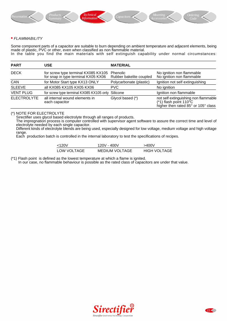
Some component parts of a capacitor are suitable to burn depending on ambient temperature and adjacent elements, beingmade of plastic, PVC or other, even when classified as non flammable material.In the table you find the main materials with self extinguish capability under normal circumstances:
PART USE MATERIAL
DECK for screw type terminal KX085 KX105 Phenolic No ignition non flammablefor snap in type terminal KX05 KX06 Rubber bakelite coupled No ignition non flammable
CAN for Motor Start type KX13 ONLY Polycarbonate (plastic) Ignition not self extinguishingSLEEVE all KX085 KX105 KX05 KX06 PVC No ignitionVENT PLUG for screw type terminal KX085 KX105 only Silicone Ignition non flammableELECTROLYTE all internal wound elements in Glycol based (*) not self extinguishing non flammable
each capacitor (*1) flash point 110°Chigher then rated 85° or 105° class
(*) NOTE FOR ELECTROLYTESirectifier uses glycol based electrolyte through all ranges of products.The impregnation process is computer controlled with supervisor agent software to assure the correct time and level ofelectrolyte needed by each single capacitor.Different kinds of electrolyte blends are being used, especially designed for low voltage, medium voltage and high voltagerange.Each production batch is controlled in the internal laboratory to test the specifications of recipes.
<120V 120V - 400V >400VLOW VOLTAGE MEDIUM VOLTAGE HIGH VOLTAGE
(*1) Flash point is defined as the lowest temperature at which a flame is ignited.In our case, no flammable behaviour is possible as the rated class of capacitors are under that value.
15
TechnicalInformation Presentation Capacitors Mounting
AccessoriesOrdering
CodeProductsSummary
16
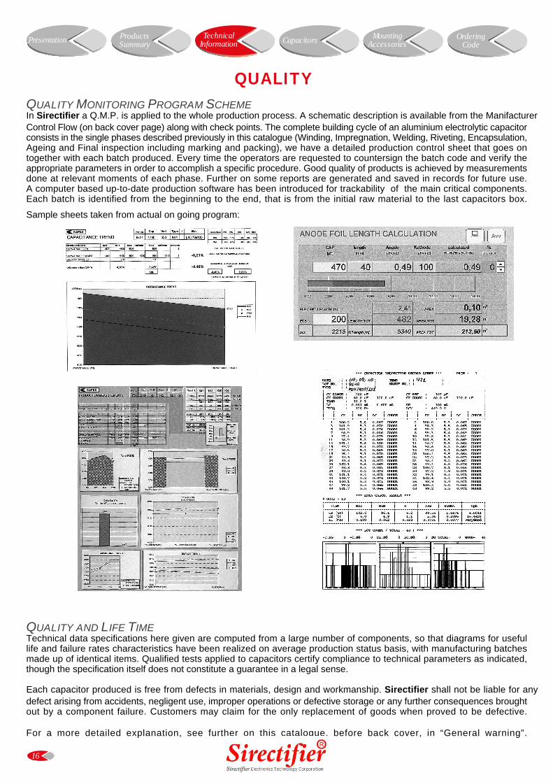
QUALITY MONITORING PROGRAM SCHEMEIn Sirectifier a Q.M.P. is applied to the whole production process. A schematic description is available from the ManifacturerControl Flow (on back cover page) along with check points. The complete building cycle of an aluminium electrolytic capacitorconsists in the single phases described previously in this catalogue (Winding, Impregnation, Welding, Riveting, Encapsulation,Ageing and Final inspection including marking and packing), we have a detailed production control sheet that goes ontogether with each batch produced. Every time the operators are requested to countersign the batch code and verify theappropriate parameters in order to accomplish a specific procedure. Good quality of products is achieved by measurementsdone at relevant moments of each phase. Further on some reports are generated and saved in records for future use.A computer based up-to-date production software has been introduced for trackability of the main critical components.Each batch is identified from the beginning to the end, that is from the initial raw material to the last capacitors box.
Sample sheets taken from actual on going program:
QUALITY AND LIFE TIMETechnical data specifications here given are computed from a large number of components, so that diagrams for usefullife and failure rates characteristics have been realized on average production status basis, with manufacturing batchesmade up of identical items. Qualified tests applied to capacitors certify compliance to technical parameters as indicated,though the specification itself does not constitute a guarantee in a legal sense.
Each capacitor produced is free from defects in materials, design and workmanship. Sirectifier shall not be liable for anydefect arising from accidents, negligent use, improper operations or defective storage or any further consequences broughtout by a component failure. Customers may claim for the only replacement of goods when proved to be defective.
For a more detailed explanation, see further on this catalogue, before back cover, in “General warning”.
QUALITY
TechnicalInformation Presentation Capacitors Mounting
AccessoriesOrdering
CodeProductsSummary
17
KX085 TYPE
• Surge-proof capacitor in aluminium can with insulation sleeve.• Poles brought out to heavy duty screw terminals.• To be mounted with ring clips or with threaded stud.
Very high CV for unit volume with low ESR.High ripple current.Excellent electricals data in small dimensions case size.
SPECIFICATIONSGENERAL CHARACTERISTICS
Temperature Range Operating: -40°C +85°C [Environmental classification 40/85/56 IEC-68]Storage : Preferably below +25°C, not exceeding +40°C
Rated Voltage Range (Vr) from 16V to 500V DC
Surge Voltage (Vp) Vp = 1.15 Vr (Vr ² 250V DC)Vp = 1.10 Vr (Vr > 250V DC)
Rated Capacitance Range from 220 µF to 1,500,000 µF
Capacitance Tolerance ±20% at 100 Hz, 20°C [M class IEC-62] on request: -10% +30% at 100 Hz, 20°C [Q class IEC-62]
Leakage Current (IL) max IL= 0.006 Cr Vr + 4 µA Sirectifier product limit : IL= 0.003 Cr Vr
(mA, 5 min, 20°C) At 85°C max IL = 0.04 Cr Vr µA
Ripple current (Ir) Refer to table at 85°C and 100Hz. For different temperature and frequency multiplier must be used as follows:
FREQUENCY 50Hz 100Hz 500 Hz 1000Hz >10kHzMULTIPLIER 0.8 1.0 1.2 1.3 1.5
AMBIENT TEMP. 35°C 45°C 55°C 65°C 75°C 85°CMULTIPLIER 2.2 2.1 1.8 1.6 1.4 1.0Maximum internal temperature 98°C
Due to the current load capability of the contact elements, the following limits must not be exceeded:CAPACITOR DIAMETER 35mm 51mm 63mm 76mm 90mmMaximum current 20A 30A 40A 50A 70A
Insulation Resistance At 100V DC for 1 min is >100 MΩ across insulating sleeve and terminals.
Vibration Resistance Frequency range: 10 Hz to 55 Hz, amplitude 0.75 mmCapacitor length ² 143 : max acceleration 10g for 3x2 hCapacitor length > 143 : max acceleration 5g for 3x0.5 h
Life test After 2,000 hours application of rated voltage at 85°C Cap change ² 20%capacitors meet characteristics aside tan δ ² 200%
Leakage current (IL) < initial limitImpedance (Z) ² 200%
Shelf life After leaving capacitors under no load for 500 hours at 85°C, Cap change ² ±15%when restored at 20°C meet specifications aside tan δ ² 150%
Leakage current (IL) < initial limit
Useful life > 200,000 h at 40°C> 10,000 h at 85°C
Failure percentage ² 1% (during useful life) Failure rate ² 40 fit (40 10-9/h (Vr ² 160V DC)
² 70 fit (70 10-9/h (Vr > 160V DC)
Self inductance Approx. 20 nH
Reference standards CECC 30.300 IEC 60384-4 LONG LIFE GRADE
APPLICATIONSDesigned for professional power electronics. Switch mode power supplies, converters, filtering devices.
Presentation Capacitors MountingAccessories
OrderingCode
ProductsSummary
TechnicalInformation
18
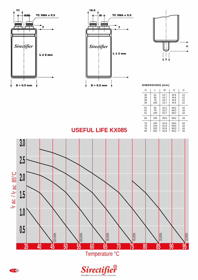
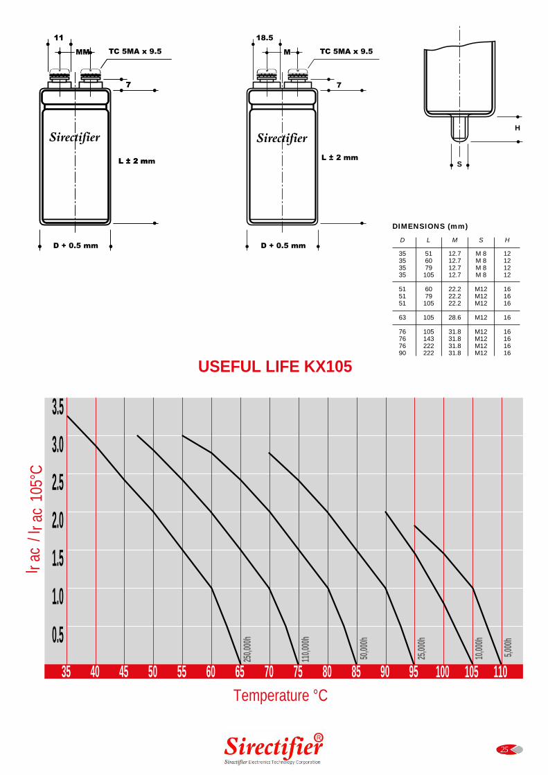
USEFUL LIFE KX085
D L M S H
35 51 12.7 M 8 1235 60 12.7 M 8 1235 79 12.7 M 8 1235 105 12.7 M 8 12
51 60 22.2 M12 1651 79 22.2 M12 1651 105 22.2 M12 16
63 105 28.6 M12 16
76 105 31.8 M12 1676 143 31.8 M12 1676 222 31.8 M12 1690 222 31.8 M12 16
DIMENSIONS (mm)
S
H
1111 18.5
MM TC 5MA x 9.5 M TC 5MA x 9.5
77 7
Sirectifier
LL ±± 22 mmm L ± 2 mm
D + 0.5 mm D + 0.5 mm
Temperature °C
I r ac
/ I r
ac 8
5°C
0.5
1.0
1.5
2.0
2.5
3.0
35 40 45 50 55 60 65 70 75 80 85 90 95
320,0
00h
160,0
00h
80,00
0h
40,00
0h
20,00
0h
10,00
0h
Sirectifier
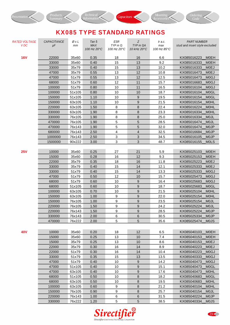
RATED VOLTAGE CAPACITANCE Ø x L Tan δ ESR Z Ir a.c. PART NUMBERV DC µF mm MAX TYP m Ω TYP m ΩA max stud and insert style excluded
100 Hz 20°C 100 Hz 20°C 10 kHz 20°C 100 Hz 85°C
16V 22000 35x60 0.35 18 16 6.6 KX085016223__M0EH
33000 35x60 0.40 15 13 9.2 KX085016333__M0EH
33000 35x79 0.40 15 13 10.2 KX085016333__M0EJ
47000 35x79 0.55 13 12 10.8 KX085016473__M0EJ
47000 51x79 0.55 13 12 12.5 KX085016473__M0GJ
68000 51x79 0.60 12 11 15.7 KX085016683__M0GJ
100000 51x79 0.80 10 11 16.5 KX085016104__M0GJ
100000 51x105 0.80 10 10 18.7 KX085016104__M0GL
150000 51x105 1.10 10 9 19.5 KX085016154__M0GL
150000 63x105 1.10 10 9 21.5 KX085016154__M0HL
220000 63x105 1.50 8 8 22.4 KX085016224__M0HL
330000 63x105 1.90 8 8 23.3 KX085016334__M0HL
330000 76x105 1.90 8 8 25.0 KX085016334__M0JL
470000 76x105 1.90 5 5 28.5 KX085016474__M0JL
470000 76x143 1.90 5 5 32.0 KX085016474__M0JP
680000 76x143 2.50 4 4 32.5 KX085016684__M0JP
1000000 76x143 2.50 3 3 34.5 KX085016105__M0JP
1500000 90x222 3.00 3 3 48.7 KX085016155__M0LS
25V 10000 35x60 0.25 27 21 5.9 KX085025103__M0EH
15000 35x60 0.28 16 12 9.3 KX085025153__M0EH
22000 35x79 0.35 18 16 11.8 KX085025223__M0EJ
33000 35x79 0.40 15 14 12.1 KX085025333__M0EJ
33000 51x79 0.40 15 14 13.3 KX085025333__M0GJ
47000 51x79 0.50 12 10 15.7 KX085025473__M0GJ
68000 51x79 0.60 10 9 16.4 KX085025683__M0GJ
68000 51x105 0.60 10 9 18.7 KX085025683__M0GL
100000 63x105 0.70 10 9 21.5 KX085025104__M0HL
150000 63x105 1.00 9 9 22.0 KX085025154__M0HL
150000 76x105 1.00 9 9 23.5 KX085025154__M0JL
220000 76x105 1.50 9 9 24.2 KX085025224__M0JL
220000 76x143 1.50 9 9 28.5 KX085025224__M0JP
330000 76x143 2.00 6 6 30.5 KX085025334__M0JP
470000 76x222 2.00 5 5 35.6 KX085025474__M0JS
40V 10000 35x60 0.20 18 12 6.5 KX085040103__M0EH
15000 35x60 0.25 13 10 7.4 KX085040153__M0EH
15000 35x79 0.25 13 10 8.6 KX085040153__M0EJ
22000 35x79 0.30 16 14 8.9 KX085040223__M0EJ
22000 51x79 0.30 16 14 10.4 KX085040223__M0GJ
33000 51x79 0.35 15 13 13.5 KX085040333__M0GJ
47000 51x79 0.40 10 9 14.2 KX085040473__M0GJ
47000 51x105 0.40 10 9 15.1 KX085040473__M0GL
47000 63x105 0.40 10 9 17.6 KX085040473__M0HL
68000 51x105 0.50 10 8 18.2 KX085040683__M0GL
68000 63x105 0.50 10 8 19.5 KX085040683__M0HL
100000 63x105 0.60 9 8 21.2 KX085040104__M0HL
150000 76x105 0.90 9 8 25.7 KX085040154__M0JL
220000 76x143 1.00 6 6 31.5 KX085040224__M0JP
330000 76x222 1.20 5 5 38.5 KX085040334__M0JS
19
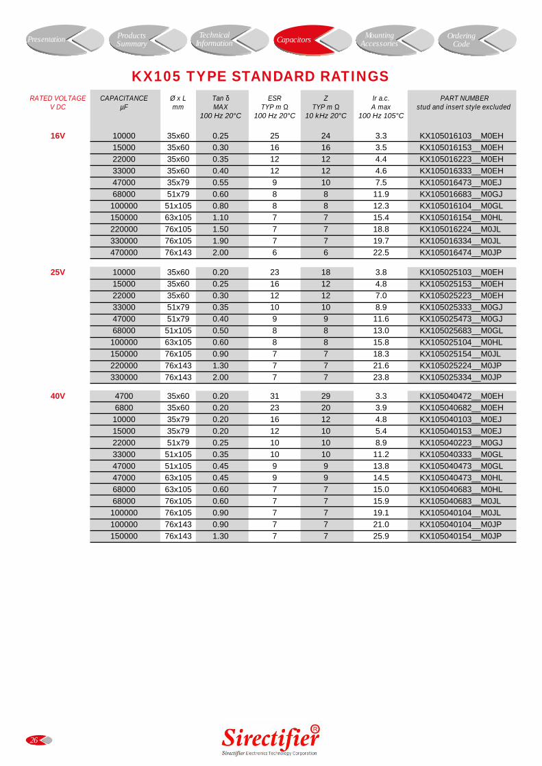
KX085 TYPE STANDARD RATINGS
Presentation Capacitors MountingAccessories
OrderingCode
ProductsSummary
TechnicalInformation

RATED VOLTAGE CAPACITANCE Ø x L Tan δ ESR Z Ir a.c. PART NUMBERV DC µF mm MAX TYP m Ω TYP m ΩA max stud and insert style excluded
100 Hz 20°C 100 Hz 20°C 10 kHz 20°C 100 Hz 85°C
50V 4700 35x60 0.20 33 30 5.6 KX085050472__M0EH
6800 35x60 0.20 25 24 7.0 KX085050682__M0EH
10000 35x60 0.20 21 20 10.0 KX085050103__M0EH
15000 35x79 0.25 17 15 11.3 KX085050153__M0EJ
22000 51x79 0.30 16 13 13.1 KX085050223__M0GJ
33000 51x105 0.35 15 13 16.0 KX085050333__M0GL
33000 63x105 0.35 15 13 17.5 KX085050333__M0HL
47000 51x105 0.40 12 10 16.2 KX085050473__M0GL
47000 63x105 0.40 12 10 18.3 KX085050473__M0HL
68000 51x105 0.60 12 9 18.0 KX085050683__M0GL
68000 76x105 0.60 12 9 22.1 KX085050683__M0JL
100000 76x105 0.90 8 8 23.8 KX085050104__M0JL
100000 76x143 0.90 8 8 25.8 KX085050104__M0JP
150000 76x143 1.00 6 6 31.5 KX085050154__M0JP
63V 4700 35x60 0.15 29 25 6.2 KX085063472__M0EH
6800 35x60 0.18 21 20 7.0 KX085063682__M0EH
6800 35x79 0.18 21 20 8.2 KX085063682__M0EJ
10000 35x79 0.20 21 20 8.7 KX085063103__M0EJ
10000 51x79 0.20 18 16 10.1 KX085063103__M0GJ
15000 51x79 0.25 15 13 11.1 KX085063153__M0GJ
22000 51x79 0.30 13 11 12.4 KX085063223__M0GJ
22000 51x105 0.30 13 11 14.6 KX085063223__M0GL
33000 51x105 0.35 11 10 15.6 KX085063333__M0GL
33000 63x105 0.35 11 10 17.9 KX085063333__M0HL
47000 51x105 0.45 10 9 15.8 KX085063473__M0GL
47000 63x105 0.45 11 10 18.8 KX085063473__M0HL
68000 76x105 0.70 11 10 25.7 KX085063683__M0JL
100000 76x105 0.70 8 8 31.5 KX085063104__M0JL
100000 76x143 0.70 8 8 34.5 KX085063104__M0JP
150000 76x143 0.95 6 6 36.1 KX085063154__M0JP
75V 4700 35x60 0.15 29 25 5.4 KX085075472__M0EH
6800 35x79 0.18 20 20 8.5 KX085075682__M0EJ
10000 51x79 0.20 18 16 11.0 KX085075103__M0GJ
15000 51x105 0.25 15 13 12.7 KX085075153__M0GL
22000 51x105 0.30 12 11 15.2 KX085075223__M0GL
22000 63x105 0.30 12 11 15.2 KX085075223__M0HL
33000 63x105 0.35 11 10 18.5 KX085075333__M0HL
33000 76x105 0.35 11 10 18.5 KX085075333__M0JL
47000 76x105 0.45 10 10 22.1 KX085075473__M0JL
47000 76x143 0.45 10 10 22.1 KX085075473__M0JP
68000 76x143 0.80 10 10 26.0 KX085075683__M0JP
100000 76x143 0.95 8 8 34.9 KX085075104__M0JP
20
KX085 TYPE STANDARD RATINGS
Presentation Capacitors MountingAccessories
OrderingCode
ProductsSummary
TechnicalInformation
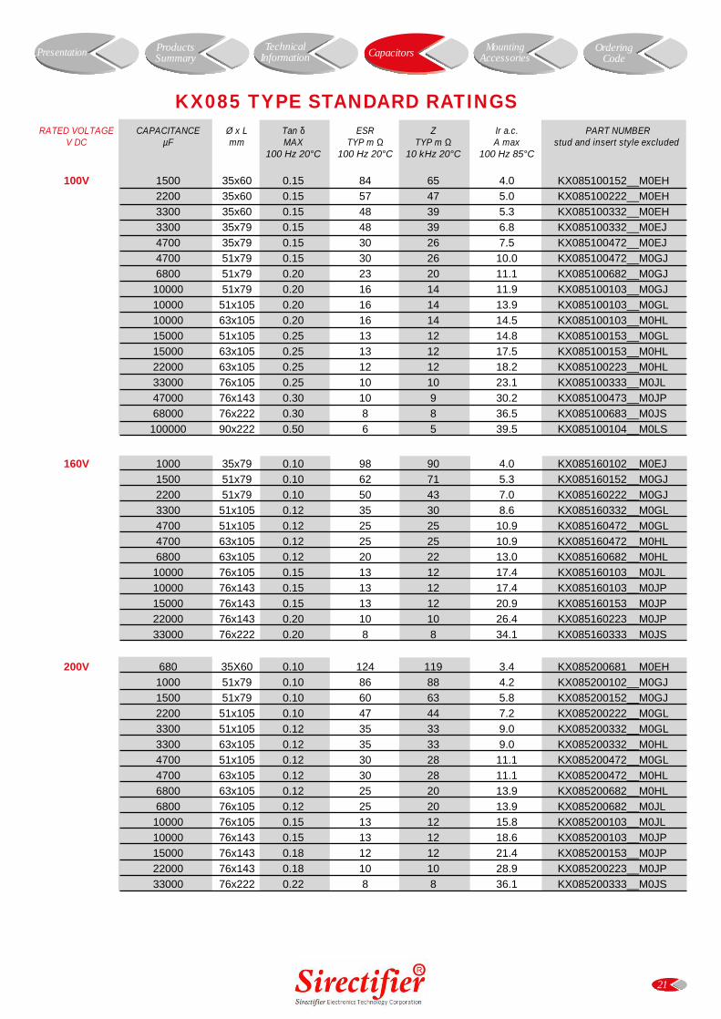
RATED VOLTAGE CAPACITANCE Ø x L Tan δ ESR Z Ir a.c. PART NUMBERV DC µF mm MAX TYP m Ω TYP m Ω A max stud and insert style excluded
100 Hz 20°C 100 Hz 20°C 10 kHz 20°C 100 Hz 85°C
100V 1500 35x60 0.15 84 65 4.0 KX085100152__M0EH
2200 35x60 0.15 57 47 5.0 KX085100222__M0EH
3300 35x60 0.15 48 39 5.3 KX085100332__M0EH
3300 35x79 0.15 48 39 6.8 KX085100332__M0EJ
4700 35x79 0.15 30 26 7.5 KX085100472__M0EJ
4700 51x79 0.15 30 26 10.0 KX085100472__M0GJ
6800 51x79 0.20 23 20 11.1 KX085100682__M0GJ
10000 51x79 0.20 16 14 11.9 KX085100103__M0GJ
10000 51x105 0.20 16 14 13.9 KX085100103__M0GL
10000 63x105 0.20 16 14 14.5 KX085100103__M0HL
15000 51x105 0.25 13 12 14.8 KX085100153__M0GL
15000 63x105 0.25 13 12 17.5 KX085100153__M0HL
22000 63x105 0.25 12 12 18.2 KX085100223__M0HL
33000 76x105 0.25 10 10 23.1 KX085100333__M0JL
47000 76x143 0.30 10 9 30.2 KX085100473__M0JP
68000 76x222 0.30 8 8 36.5 KX085100683__M0JS
100000 90x222 0.50 6 5 39.5 KX085100104__M0LS
160V 1000 35x79 0.10 98 90 4.0 KX085160102__M0EJ
1500 51x79 0.10 62 71 5.3 KX085160152__M0GJ
2200 51x79 0.10 50 43 7.0 KX085160222__M0GJ
3300 51x105 0.12 35 30 8.6 KX085160332__M0GL
4700 51x105 0.12 25 25 10.9 KX085160472__M0GL
4700 63x105 0.12 25 25 10.9 KX085160472__M0HL
6800 63x105 0.12 20 22 13.0 KX085160682__M0HL
10000 76x105 0.15 13 12 17.4 KX085160103__M0JL
10000 76x143 0.15 13 12 17.4 KX085160103__M0JP
15000 76x143 0.15 13 12 20.9 KX085160153__M0JP
22000 76x143 0.20 10 10 26.4 KX085160223__M0JP
33000 76x222 0.20 8 8 34.1 KX085160333__M0JS
200V 680 35X60 0.10 124 119 3.4 KX085200681__M0EH
1000 51x79 0.10 86 88 4.2 KX085200102__M0GJ
1500 51x79 0.10 60 63 5.8 KX085200152__M0GJ
2200 51x105 0.10 47 44 7.2 KX085200222__M0GL
3300 51x105 0.12 35 33 9.0 KX085200332__M0GL
3300 63x105 0.12 35 33 9.0 KX085200332__M0HL
4700 51x105 0.12 30 28 11.1 KX085200472__M0GL
4700 63x105 0.12 30 28 11.1 KX085200472__M0HL
6800 63x105 0.12 25 20 13.9 KX085200682__M0HL
6800 76x105 0.12 25 20 13.9 KX085200682__M0JL
10000 76x105 0.15 13 12 15.8 KX085200103__M0JL
10000 76x143 0.15 13 12 18.6 KX085200103__M0JP
15000 76x143 0.18 12 12 21.4 KX085200153__M0JP
22000 76x143 0.18 10 10 28.9 KX085200223__M0JP
33000 76x222 0.22 8 8 36.1 KX085200333__M0JS
21
KX085 TYPE STANDARD RATINGS
Presentation Capacitors MountingAccessories
OrderingCode
ProductsSummary
TechnicalInformation
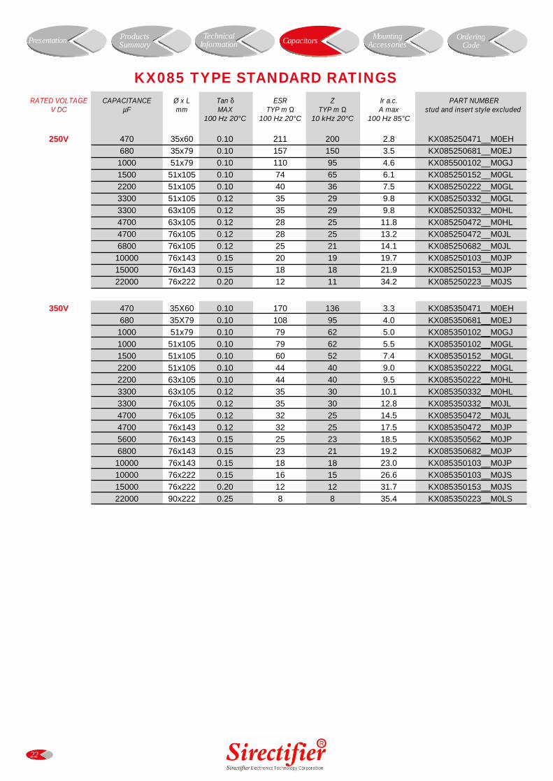
RATED VOLTAGE CAPACITANCE Ø x L Tan δ ESR Z Ir a.c. PART NUMBERV DC µF mm MAX TYP m Ω TYP m Ω A max stud and insert style excluded
100 Hz 20°C 100 Hz 20°C 10 kHz 20°C 100 Hz 85°C
250V 470 35x60 0.10 211 200 2.8 KX085250471__M0EH
680 35x79 0.10 157 150 3.5 KX085250681__M0EJ
1000 51x79 0.10 110 95 4.6 KX085500102__M0GJ
1500 51x105 0.10 74 65 6.1 KX085250152__M0GL
2200 51x105 0.10 40 36 7.5 KX085250222__M0GL
3300 51x105 0.12 35 29 9.8 KX085250332__M0GL
3300 63x105 0.12 35 29 9.8 KX085250332__M0HL
4700 63x105 0.12 28 25 11.8 KX085250472__M0HL
4700 76x105 0.12 28 25 13.2 KX085250472__M0JL
6800 76x105 0.12 25 21 14.1 KX085250682__M0JL
10000 76x143 0.15 20 19 19.7 KX085250103__M0JP
15000 76x143 0.15 18 18 21.9 KX085250153__M0JP
22000 76x222 0.20 12 11 34.2 KX085250223__M0JS
350V 470 35X60 0.10 170 136 3.3 KX085350471__M0EH
680 35X79 0.10 108 95 4.0 KX085350681__M0EJ
1000 51x79 0.10 79 62 5.0 KX085350102__M0GJ
1000 51x105 0.10 79 62 5.5 KX085350102__M0GL
1500 51x105 0.10 60 52 7.4 KX085350152__M0GL
2200 51x105 0.10 44 40 9.0 KX085350222__M0GL
2200 63x105 0.10 44 40 9.5 KX085350222__M0HL
3300 63x105 0.12 35 30 10.1 KX085350332__M0HL
3300 76x105 0.12 35 30 12.8 KX085350332__M0JL
4700 76x105 0.12 32 25 14.5 KX085350472__M0JL
4700 76x143 0.12 32 25 17.5 KX085350472__M0JP
5600 76x143 0.15 25 23 18.5 KX085350562__M0JP
6800 76x143 0.15 23 21 19.2 KX085350682__M0JP
10000 76x143 0.15 18 18 23.0 KX085350103__M0JP
10000 76x222 0.15 16 15 26.6 KX085350103__M0JS
15000 76x222 0.20 12 12 31.7 KX085350153__M0JS
22000 90x222 0.25 8 8 35.4 KX085350223__M0LS
22
KX085 TYPE STANDARD RATINGS
Presentation Capacitors MountingAccessories
OrderingCode
ProductsSummary
TechnicalInformation
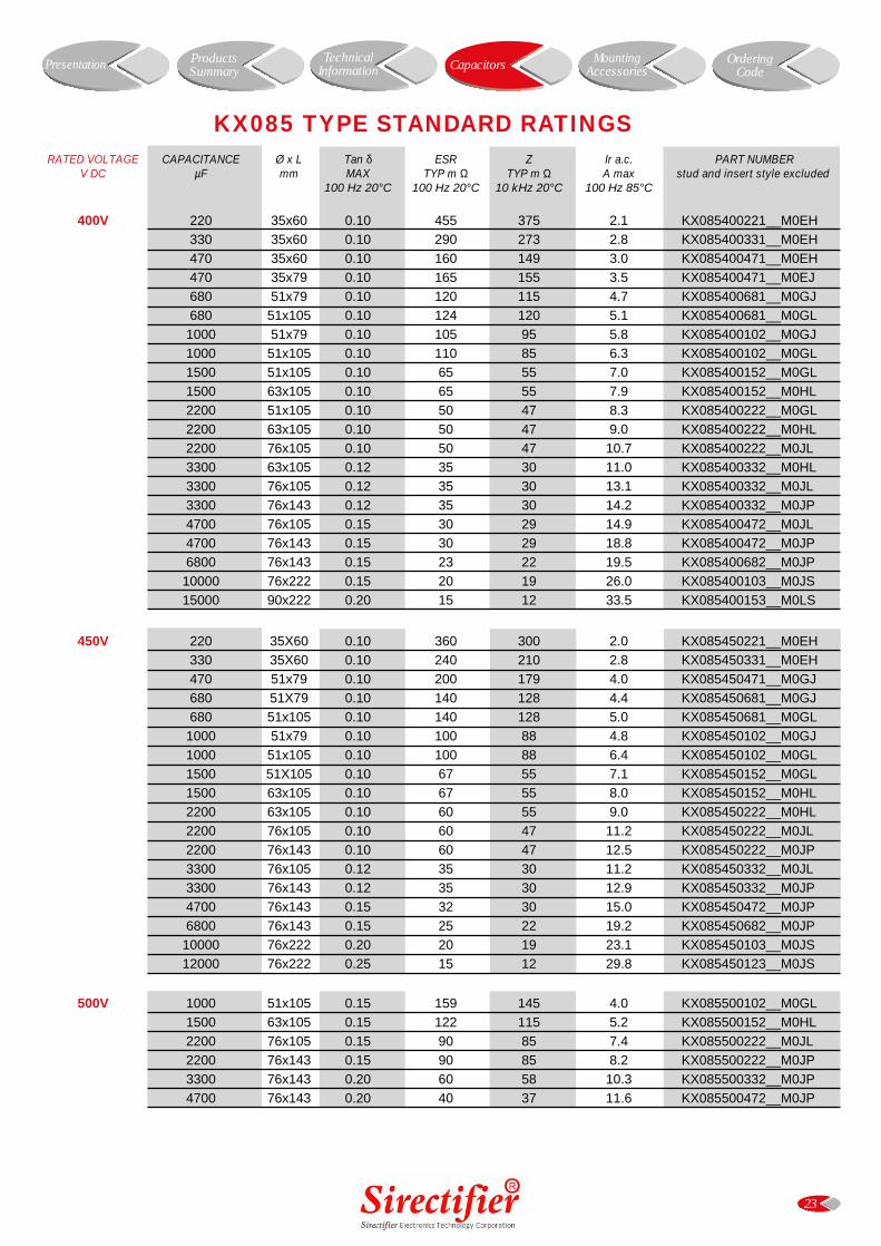
RATED VOLTAGE CAPACITANCE Ø x L Tan δ ESR Z Ir a.c. PART NUMBERV DC µF mm MAX TYP m Ω TYP m Ω A max stud and insert style excluded
100 Hz 20°C 100 Hz 20°C 10 kHz 20°C 100 Hz 85°C
400V 220 35x60 0.10 455 375 2.1 KX085400221__M0EH
330 35x60 0.10 290 273 2.8 KX085400331__M0EH
470 35x60 0.10 160 149 3.0 KX085400471__M0EH
470 35x79 0.10 165 155 3.5 KX085400471__M0EJ
680 51x79 0.10 120 115 4.7 KX085400681__M0GJ
680 51x105 0.10 124 120 5.1 KX085400681__M0GL
1000 51x79 0.10 105 95 5.8 KX085400102__M0GJ
1000 51x105 0.10 110 85 6.3 KX085400102__M0GL
1500 51x105 0.10 65 55 7.0 KX085400152__M0GL
1500 63x105 0.10 65 55 7.9 KX085400152__M0HL
2200 51x105 0.10 50 47 8.3 KX085400222__M0GL
2200 63x105 0.10 50 47 9.0 KX085400222__M0HL
2200 76x105 0.10 50 47 10.7 KX085400222__M0JL
3300 63x105 0.12 35 30 11.0 KX085400332__M0HL
3300 76x105 0.12 35 30 13.1 KX085400332__M0JL
3300 76x143 0.12 35 30 14.2 KX085400332__M0JP
4700 76x105 0.15 30 29 14.9 KX085400472__M0JL
4700 76x143 0.15 30 29 18.8 KX085400472__M0JP
6800 76x143 0.15 23 22 19.5 KX085400682__M0JP
10000 76x222 0.15 20 19 26.0 KX085400103__M0JS
15000 90x222 0.20 15 12 33.5 KX085400153__M0LS
450V 220 35X60 0.10 360 300 2.0 KX085450221__M0EH
330 35X60 0.10 240 210 2.8 KX085450331__M0EH
470 51x79 0.10 200 179 4.0 KX085450471__M0GJ
680 51X79 0.10 140 128 4.4 KX085450681__M0GJ
680 51x105 0.10 140 128 5.0 KX085450681__M0GL
1000 51x79 0.10 100 88 4.8 KX085450102__M0GJ
1000 51x105 0.10 100 88 6.4 KX085450102__M0GL
1500 51X105 0.10 67 55 7.1 KX085450152__M0GL
1500 63x105 0.10 67 55 8.0 KX085450152__M0HL
2200 63x105 0.10 60 55 9.0 KX085450222__M0HL
2200 76x105 0.10 60 47 11.2 KX085450222__M0JL
2200 76x143 0.10 60 47 12.5 KX085450222__M0JP
3300 76x105 0.12 35 30 11.2 KX085450332__M0JL
3300 76x143 0.12 35 30 12.9 KX085450332__M0JP
4700 76x143 0.15 32 30 15.0 KX085450472__M0JP
6800 76x143 0.15 25 22 19.2 KX085450682__M0JP
10000 76x222 0.20 20 19 23.1 KX085450103__M0JS
12000 76x222 0.25 15 12 29.8 KX085450123__M0JS
500V 1000 51x105 0.15 159 145 4.0 KX085500102__M0GL
1500 63x105 0.15 122 115 5.2 KX085500152__M0HL
2200 76x105 0.15 90 85 7.4 KX085500222__M0JL
2200 76x143 0.15 90 85 8.2 KX085500222__M0JP
3300 76x143 0.20 60 58 10.3 KX085500332__M0JP
4700 76x143 0.20 40 37 11.6 KX085500472__M0JP
23
KX085 TYPE STANDARD RATINGS
Presentation Capacitors MountingAccessories
OrderingCode
ProductsSummary
TechnicalInformation
24
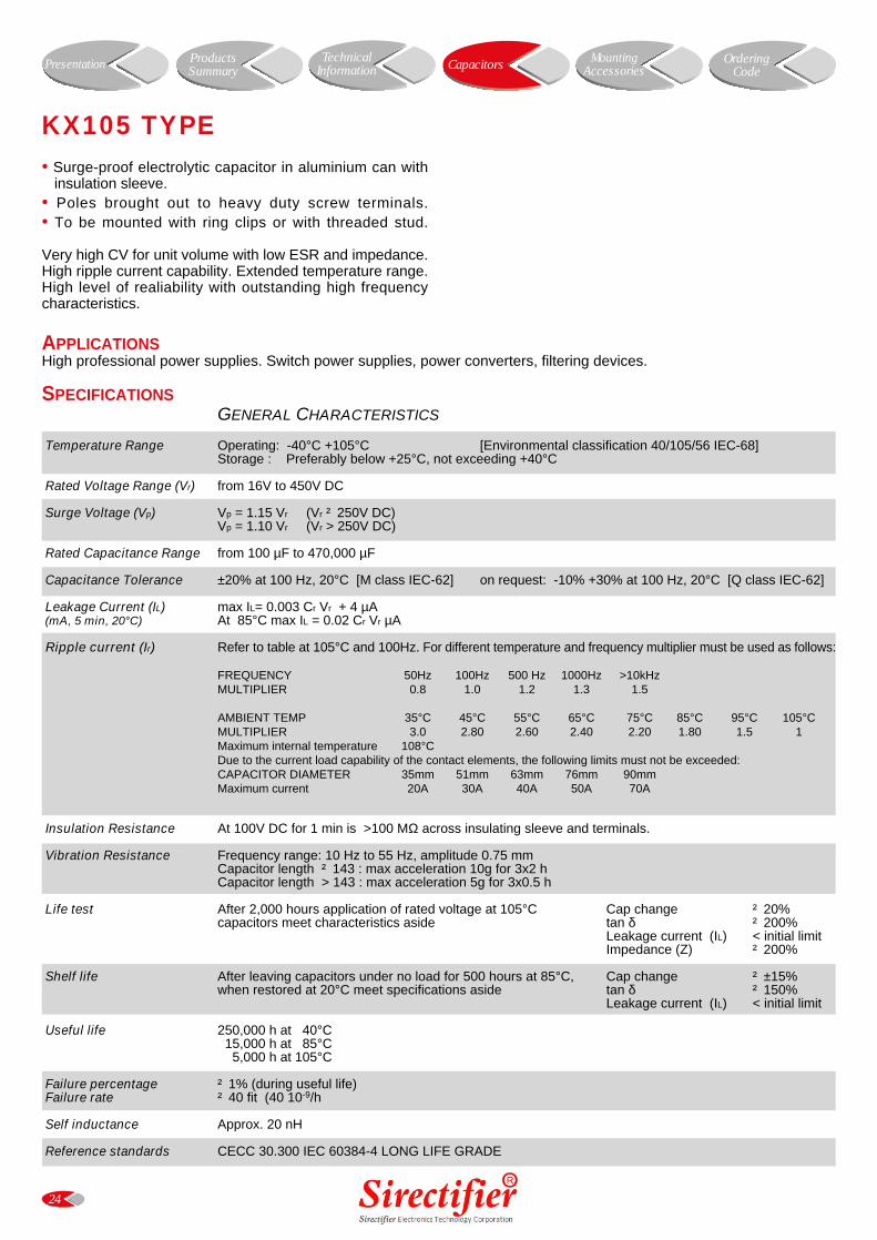
KX105 TYPE
• Surge-proof electrolytic capacitor in aluminium can withinsulation sleeve.
• Poles brought out to heavy duty screw terminals.• To be mounted with ring clips or with threaded stud.
Very high CV for unit volume with low ESR and impedance.High ripple current capability. Extended temperature range.High level of realiability with outstanding high frequencycharacteristics.
APPLICATIONSHigh professional power supplies. Switch power supplies, power converters, filtering devices.
SPECIFICATIONSGENERAL CHARACTERISTICS
Temperature Range Operating: -40°C +105°C [Environmental classification 40/105/56 IEC-68]Storage : Preferably below +25°C, not exceeding +40°C
Rated Voltage Range (Vr) from 16V to 450V DC
Surge Voltage (Vp) Vp = 1.15 Vr (Vr ² 250V DC)Vp = 1.10 Vr (Vr > 250V DC)
Rated Capacitance Range from 100 µF to 470,000 µF
Capacitance Tolerance ±20% at 100 Hz, 20°C [M class IEC-62] on request: -10% +30% at 100 Hz, 20°C [Q class IEC-62]
Leakage Current (IL) max IL= 0.003 Cr Vr + 4 µA (mA, 5 min, 20°C) At 85°C max IL = 0.02 Cr Vr µA
Ripple current (Ir) Refer to table at 105°C and 100Hz. For different temperature and frequency multiplier must be used as follows:
FREQUENCY 50Hz 100Hz 500 Hz 1000Hz >10kHzMULTIPLIER 0.8 1.0 1.2 1.3 1.5
AMBIENT TEMP 35°C 45°C 55°C 65°C 75°C 85°C 95°C 105°CMULTIPLIER 3.0 2.80 2.60 2.40 2.20 1.80 1.5 1Maximum internal temperature 108°CDue to the current load capability of the contact elements, the following limits must not be exceeded:CAPACITOR DIAMETER 35mm 51mm 63mm 76mm 90mmMaximum current 20A 30A 40A 50A 70A
Insulation Resistance At 100V DC for 1 min is >100 MΩ across insulating sleeve and terminals.
Vibration Resistance Frequency range: 10 Hz to 55 Hz, amplitude 0.75 mmCapacitor length ² 143 : max acceleration 10g for 3x2 hCapacitor length > 143 : max acceleration 5g for 3x0.5 h
Life test After 2,000 hours application of rated voltage at 105°C Cap change ² 20%capacitors meet characteristics aside tan δ ² 200%
Leakage current (IL) < initial limitImpedance (Z) ² 200%
Shelf life After leaving capacitors under no load for 500 hours at 85°C, Cap change ² ±15%when restored at 20°C meet specifications aside tan δ ² 150%
Leakage current (IL) < initial limit
Useful life 250,000 h at 40°C 15,000 h at 85°C 5,000 h at 105°C
Failure percentage ² 1% (during useful life) Failure rate ² 40 fit (40 10-9/h
Self inductance Approx. 20 nH
Reference standards CECC 30.300 IEC 60384-4 LONG LIFE GRADE
Presentation Capacitors MountingAccessories
OrderingCode
ProductsSummary
TechnicalInformation
25
S
H
D L M S H
35 51 12.7 M 8 1235 60 12.7 M 8 1235 79 12.7 M 8 1235 105 12.7 M 8 12
51 60 22.2 M12 1651 79 22.2 M12 1651 105 22.2 M12 16
63 105 28.6 M12 16
76 105 31.8 M12 1676 143 31.8 M12 1676 222 31.8 M12 1690 222 31.8 M12 16
DIMENSIONS (mm)
USEFUL LIFE KX105
0.5
1.0
1.5
2.0
2.5
3.0
250,0
00h
110,0
00h
50,00
0h
25,00
0h3.5
10,00
0h
5,000
h
35 40 45 50 55 60 65 70 75 80 85 90 95 100 105 110
Temperature °C
I r ac
/ I r
ac 1
05°C
1111 18.5
MM TC 5MA x 9.5 M TC 5MA x 9.5
77 7
Sirectifier
LL ±± 22 mmm L ± 2 mm
D + 0.5 mm D + 0.5 mm
Sirectifier
RATED VOLTAGE CAPACITANCE Ø x L Tan δ ESR Z Ir a.c. PART NUMBERV DC µF mm MAX TYP m Ω TYP m Ω A max stud and insert style excluded
100 Hz 20°C 100 Hz 20°C 10 kHz 20°C 100 Hz 105°C
16V 10000 35x60 0.25 25 24 3.3 KX105016103__M0EH
15000 35x60 0.30 16 16 3.5 KX105016153__M0EH
22000 35x60 0.35 12 12 4.4 KX105016223__M0EH
33000 35x60 0.40 12 12 4.6 KX105016333__M0EH
47000 35x79 0.55 9 10 7.5 KX105016473__M0EJ
68000 51x79 0.60 8 8 11.9 KX105016683__M0GJ
100000 51x105 0.80 8 8 12.3 KX105016104__M0GL
150000 63x105 1.10 7 7 15.4 KX105016154__M0HL
220000 76x105 1.50 7 7 18.8 KX105016224__M0JL
330000 76x105 1.90 7 7 19.7 KX105016334__M0JL
470000 76x143 2.00 6 6 22.5 KX105016474__M0JP
25V 10000 35x60 0.20 23 18 3.8 KX105025103__M0EH
15000 35x60 0.25 16 12 4.8 KX105025153__M0EH
22000 35x60 0.30 12 12 7.0 KX105025223__M0EH
33000 51x79 0.35 10 10 8.9 KX105025333__M0GJ
47000 51x79 0.40 9 9 11.6 KX105025473__M0GJ
68000 51x105 0.50 8 8 13.0 KX105025683__M0GL
100000 63x105 0.60 8 8 15.8 KX105025104__M0HL
150000 76x105 0.90 7 7 18.3 KX105025154__M0JL
220000 76x143 1.30 7 7 21.6 KX105025224__M0JP
330000 76x143 2.00 7 7 23.8 KX105025334__M0JP
40V 4700 35x60 0.20 31 29 3.3 KX105040472__M0EH
6800 35x60 0.20 23 20 3.9 KX105040682__M0EH
10000 35x79 0.20 16 12 4.8 KX105040103__M0EJ
15000 35x79 0.20 12 10 5.4 KX105040153__M0EJ
22000 51x79 0.25 10 10 8.9 KX105040223__M0GJ
33000 51x105 0.35 10 10 11.2 KX105040333__M0GL
47000 51x105 0.45 9 9 13.8 KX105040473__M0GL
47000 63x105 0.45 9 9 14.5 KX105040473__M0HL
68000 63x105 0.60 7 7 15.0 KX105040683__M0HL
68000 76x105 0.60 7 7 15.9 KX105040683__M0JL
100000 76x105 0.90 7 7 19.1 KX105040104__M0JL
100000 76x143 0.90 7 7 21.0 KX105040104__M0JP
150000 76x143 1.30 7 7 25.9 KX105040154__M0JP
26
KX105 TYPE STANDARD RATINGS
Presentation Capacitors MountingAccessories
OrderingCode
ProductsSummary
TechnicalInformation
RATED VOLTAGE CAPACITANCE Ø x L Tan δ ESR Z Ir a.c. PART NUMBERV DC µF mm MAX TYP m Ω TYP m Ω A max stud and insert style excluded
100 Hz 20°C 100 Hz 20°C 10 kHz 20°C 100 Hz 105°C
63V 2200 35x60 0.15 72 60 2.5 KX105063222__M0EH
3300 35x60 0.15 48 39 3.5 KX105063332__M0EH
4700 35x60 0.15 33 28 4.2 KX105063472__M0EH
6800 35x79 0.18 18 13 6.3 KX105063682__M0EJ
10000 51x79 0.20 15 11 8.2 KX105063103__M0GJ
15000 51x79 0.25 15 13 8.9 KX105063153__M0GJ
15000 51x105 0.25 13 10 18.0 KX105063153__M0GL
22000 51x105 0.30 11 10 11.8 KX105063223__M0GL
22000 63x105 0.30 11 10 13.5 KX105063223__M0HL
33000 63x105 0.35 11 10 14.8 KX105063333__M0HL
33000 76x105 0.35 11 8 16.6 KX105063333__M0JL
47000 76x105 0.45 9 8 17.7 KX105063473__M0JL
47000 76x143 0.45 9 8 19.0 KX105063473__M0JP
68000 76x105 0.45 8 8 20.1 KX105063683__M0JL
68000 76x143 0.70 8 8 22.8 KX105063683__M0JP
100000 76x143 0.70 8 8 24.1 KX105063104__M0JP
100V 1000 35x60 0.15 110 100 2.9 KX105100102__M0EH
1500 35x60 0.15 80 73 3.2 KX105100152__M0EH
2200 35x60 0.15 59 53 4.4 KX105100222__M0EH
3300 35x79 0.15 33 31 5.8 KX105100332__M0EJ
4700 51x79 0.15 25 22 7.2 KX105100472__M0GJ
6800 51x105 0.15 19 17 8.9 KX105100682__M0GL
10000 51x105 0.15 17 15 11.0 KX105100103__M0GL
10000 63x105 0.15 17 15 12.5 KX105100103__M0HL
15000 63x105 0.15 12 12 15.1 KX105100153__M0HL
22000 76x105 0.18 10 9 16.5 KX105100223__M0JL
33000 76x143 0.22 8 8 20.9 KX105100333__M0JP
160V 1000 35x79 0.11 105 90 3.3 KX105160102__M0EJ
1500 51x79 0.11 65 60 4.1 KX105160152__M0GJ
2200 51X105 0.11 46 43 4.8 KX105160222__M0GL
3300 63x105 0.11 32 30 6.8 KX105160332__M0HL
4700 63x105 0.11 27 25 8.5 KX105160472__M0HL
6800 76x105 0.13 23 20 11.3 KX105160682__M0JL
10000 76x143 0.15 17 16 14.9 KX105160103__M0JP
15000 76x143 0.20 16 12 17.2 KX105160153__M0JP
22000 76X222 0.20 11 10 19.0 KX105160223__M0JS
200V 680 35X60 0.11 133 98 2.5 KX105200681__M0EH
1000 51x79 0.11 85 64 4.6 KX105200102__M0GJ
1500 51x105 0.11 65 58 5.1 KX105200152__M0GL
2200 51x105 0.11 60 53 6.1 KX105200222__M0GL
3300 63x105 0.11 40 35 7.9 KX105200332__M0HL
4700 63x105 0.11 30 28 8.7 KX105200472__M0HL
6800 76X105 0.11 23 12 11.8 KX105200682__M0JL
10000 76x143 0.15 19 12 16.0 KX105200103__M0JP
15000 76x143 0.20 19 12 17.3 KX105200153__M0JP
22000 76x222 0.20 11 10 18.9 KX105200223__M0JS
27
KX105 TYPE STANDARD RATINGS
Presentation Capacitors MountingAccessories
OrderingCode
ProductsSummary
TechnicalInformation
RATED VOLTAGE CAPACITANCE Ø x L Tan δ ESR Z Ir a.c. PART NUMBERV DC µF mm MAX TYP m Ω TYP m Ω A max stud and insert style excluded
100 Hz 20°C 100 Hz 20°C 10 kHz 20°C 100 Hz 105°C
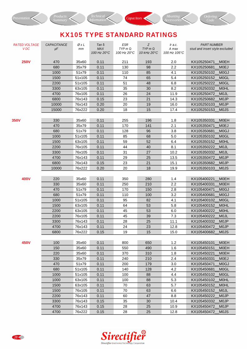
250V 470 35x60 0.11 211 193 2.0 KX105250471__M0EH
680 35x79 0.11 130 98 2.2 KX105250681__M0EJ
1000 51x79 0.11 110 85 4.1 KX105250102__M0GJ
1500 51x105 0.11 74 65 5.4 KX105250152__M0GL
2200 51x105 0.11 51 48 6.8 KX105250222__M0GL
3300 63x105 0.11 35 30 8.2 KX105250332__M0HL
4700 76x105 0.11 26 24 11.9 KX105250472__M0JL
6800 76x143 0.15 23 21 14.3 KX105250682__M0JP
10000 76x143 0.20 20 19 16.0 KX105250103__M0JP
15000 76x222 0.20 18 15 17.4 KX105250153__M0JS
350V 330 35x60 0.11 255 196 1.8 KX105350331__M0EH
470 35x79 0.11 170 141 2.1 KX105350471__M0EJ
680 51x79 0.11 128 96 3.8 KX105350681__M0GJ
1000 51x105 0.11 85 68 5.0 KX105350102__M0GL
1500 63x105 0.11 59 52 6.4 KX105350152__M0HL
2200 76x105 0.11 44 40 8.1 KX105350222__M0JL
3300 76x105 0.11 31 27 10.2 KX105350332__M0JL
4700 76x143 0.11 29 25 13.5 KX105350472__M0JP
6800 76x143 0.15 23 21 15.1 KX105350682__M0JP
10000 76x222 0.20 20 18 19.9 KX105350103__M0JS
400V 220 35x60 0.11 350 280 1.4 KX105400221__M0EH
330 35x60 0.11 250 210 2.2 KX105400331__M0EH
470 51x79 0.11 170 150 2.8 KX105400471__M0GJ
680 51x79 0.11 110 100 3.2 KX105400681__M0GJ
1000 51x105 0.11 95 82 4.1 KX105400102__M0GL
1500 63x105 0.11 64 53 5.8 KX105400152__M0HL
2200 63x105 0.11 45 53 6.0 KX105400222__M0HL
2200 76x105 0.11 45 39 7.3 KX105400222__M0JL
3300 76x143 0.11 28 25 11.1 KX105400332__M0JP
4700 76x143 0.11 24 23 12.8 KX105400472__M0JP
6800 76x222 0.15 19 15 15.0 KX105400682__M0JS
450V 100 35x60 0.11 800 650 1.2 KX105450101__M0EH
150 35x60 0.11 550 490 1.6 KX105450151__M0EH
220 35x60 0.11 370 310 1.8 KX105450221__M0EH
330 35x79 0.11 240 210 2.4 KX105450331__M0EJ
470 51x79 0.11 200 179 3.0 KX105450471__M0GJ
680 51x105 0.11 140 128 4.2 KX105450681__M0GL
1000 51x105 0.11 100 88 4.4 KX105450102__M0GL
1000 63x105 0.11 100 88 5.3 KX105450102__M0HL
1500 63x105 0.11 70 63 5.7 KX105450152__M0HL
1500 76x105 0.11 70 63 6.6 KX105450152__M0JL
2200 76x143 0.11 60 47 8.8 KX105450222__M0JP
3300 76x143 0.15 35 30 10.4 KX105450332__M0JP
4700 76x143 0.15 28 25 10.9 KX105450472__M0JP
4700 76x222 0.15 28 25 12.8 KX105450472__M0JS
28
KX105 TYPE STANDARD RATINGS
Presentation Capacitors MountingAccessories
OrderingCode
ProductsSummary
TechnicalInformation
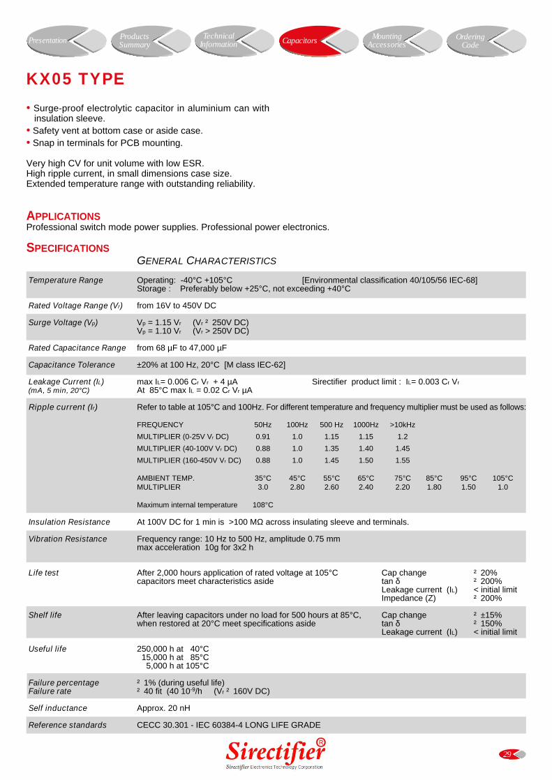
29
KX05 TYPE
• Surge-proof electrolytic capacitor in aluminium can withinsulation sleeve.
• Safety vent at bottom case or aside case.• Snap in terminals for PCB mounting.
Very high CV for unit volume with low ESR.High ripple current, in small dimensions case size.Extended temperature range with outstanding reliability.
SPECIFICATIONSGENERAL CHARACTERISTICS
Temperature Range Operating: -40°C +105°C [Environmental classification 40/105/56 IEC-68]Storage : Preferably below +25°C, not exceeding +40°C
Rated Voltage Range (Vr) from 16V to 450V DC
Surge Voltage (Vp) Vp = 1.15 Vr (Vr ² 250V DC)Vp = 1.10 Vr (Vr > 250V DC)
Rated Capacitance Range from 68 µF to 47,000 µF
Capacitance Tolerance ±20% at 100 Hz, 20°C [M class IEC-62]
Leakage Current (IL) max IL= 0.006 Cr Vr + 4 µA Sirectifier product limit : IL= 0.003 Cr Vr
(mA, 5 min, 20°C) At 85°C max IL = 0.02 Cr Vr µA
Ripple current (Ir) Refer to table at 105°C and 100Hz. For different temperature and frequency multiplier must be used as follows:
FREQUENCY 50Hz 100Hz 500 Hz 1000Hz >10kHz
MULTIPLIER (0-25V Vr DC) 0.91 1.0 1.15 1.15 1.2
MULTIPLIER (40-100V Vr DC) 0.88 1.0 1.35 1.40 1.45
MULTIPLIER (160-450V Vr DC) 0.88 1.0 1.45 1.50 1.55
AMBIENT TEMP. 35°C 45°C 55°C 65°C 75°C 85°C 95°C 105°CMULTIPLIER 3.0 2.80 2.60 2.40 2.20 1.80 1.50 1.0
Maximum internal temperature 108°C
Insulation Resistance At 100V DC for 1 min is >100 MΩ across insulating sleeve and terminals.
Vibration Resistance Frequency range: 10 Hz to 500 Hz, amplitude 0.75 mmmax acceleration 10g for 3x2 h
Life test After 2,000 hours application of rated voltage at 105°C Cap change ² 20%capacitors meet characteristics aside tan δ ² 200%
Leakage current (IL) < initial limitImpedance (Z) ² 200%
Shelf life After leaving capacitors under no load for 500 hours at 85°C, Cap change ² ±15%when restored at 20°C meet specifications aside tan δ ² 150%
Leakage current (IL) < initial limit
Useful life 250,000 h at 40°C 15,000 h at 85°C 5,000 h at 105°C
Failure percentage ² 1% (during useful life) Failure rate ² 40 fit (40 10-9/h (Vr ² 160V DC)
Self inductance Approx. 20 nH
Reference standards CECC 30.301 - IEC 60384-4 LONG LIFE GRADE
APPLICATIONSProfessional switch mode power supplies. Professional power electronics.
Presentation Capacitors MountingAccessories
OrderingCode
ProductsSummary
TechnicalInformation
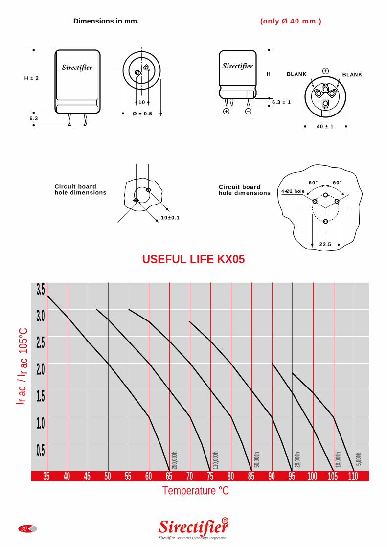
30
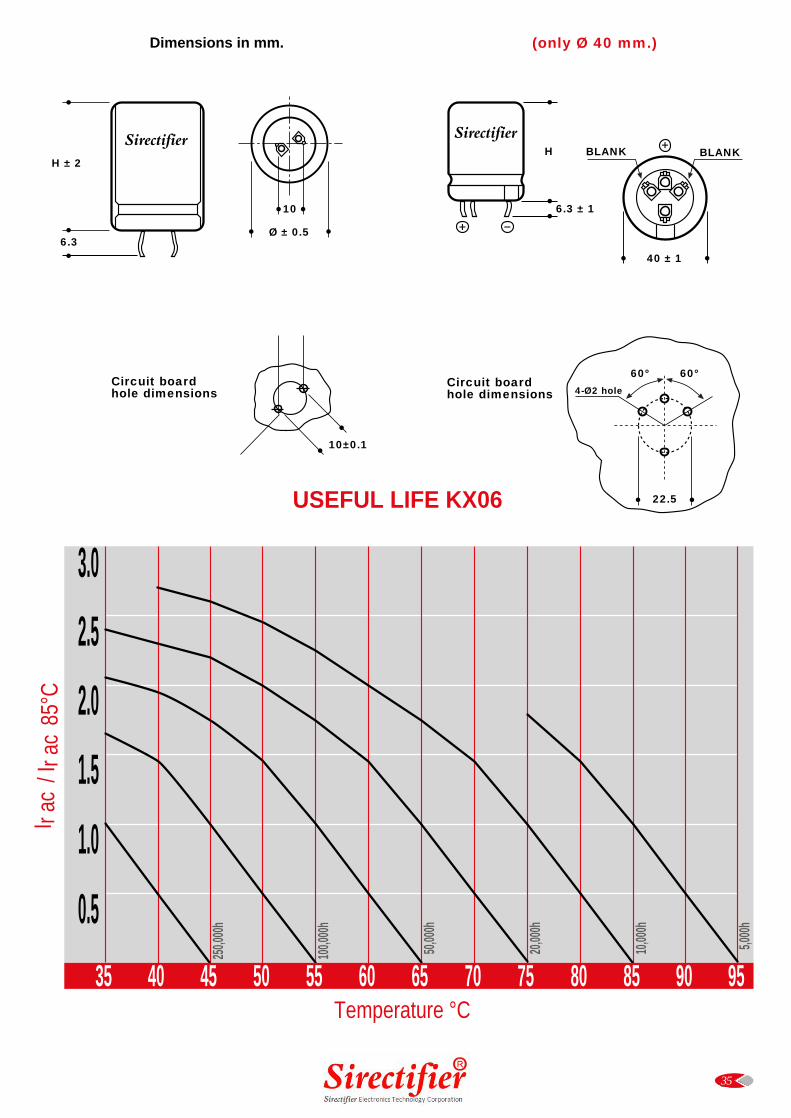
Dimensions in mm.
0.5
1.0
1.5
2.0
2.5
3.0
250,0
00h
110,0
00h
50,00
0h
25,00
0h3.5
10,00
0h
5,000
h
35 40 45 50 55 60 65 70 75 80 85 90 95 100 105 110Temperature °C
I r ac
/ I r
ac 1
05°C
Circuit boardhole dimensions
H ± 2
6.3
10
Ø ± 0.5
10±0.1
(only Ø 40 mm.)
H
6.3 ± 1
40 ± 1
BLANK BLANK
22.5
4-Ø2 hole
60° 60°Circuit boardhole dimensions
USEFUL LIFE KX05
Sirectifier Sirectifier
RATED VOLTAGE CAPACITANCE Ø x L Tan δ ESR Z Ir a.c. PART NUMBERV DC µF mm MAX TYP m Ω TYP m Ω A max stud and insert style excluded
100 Hz 20°C 100 Hz 20°C 10 kHz 20°C 100 Hz 105°C
16V 6800 25x30 0.30 55 40 1.9 KX05016682_PM0CB
10000 25x40 0.40 45 35 2.0 KX05016103_PM0CD
10000 30x30 0.40 40 35 2.0 KX05016103_PM0DB
15000 25x40 0.45 40 35 2.6 KX05016153_PM0CD
15000 30x40 0.45 40 35 2.8 KX05016153_PM0DD
22000 30x40 0.60 35 24 3.1 KX05016223_PM0DD
22000 35x40 0.60 35 24 3.3 KX05016223_PM0ED
33000 35x50 0.70 25 20 3.6 KX05016333_PM0EF
47000 35x50 0.90 22 20 4.9 KX05016473_PM0EF
25V 4700 25x30 0.25 53 45 1.8 KX05025472_PM0CB
6800 25x30 0.25 50 38 2.0 KX05025682_PM0CB
6800 30x30 0.30 50 38 2.2 KX05025682_PM0DB
10000 25x40 0.40 40 35 2.4 KX05025103_PM0CD
10000 30x30 0.40 40 35 2.3 KX05025103_PM0DB
15000 30x40 0.45 39 28 2.9 KX05025153_PM0DD
15000 35x40 0.45 39 28 3.2 KX05025153_PM0ED
22000 35x50 0.60 30 22 3.3 KX05025223_PM0EF
33000 35x50 0.70 22 18 4.3 KX05025333_PM0EF
40V 3300 25x30 0.20 72 58 1.5 KX05040332_PM0CB
4700 25x30 0.20 50 38 1.8 KX05040472_PM0CB
4700 30x25 0.20 50 38 1.8 KX05040472_PM0DA
6800 25x40 0.30 48 33 2.3 KX05040682_PM0CD
6800 30x30 0.30 48 33 2.4 KX05040682_PM0DB
10000 30x40 0.40 39 28 2.8 KX05040103_PM0DD
10000 35x30 0.40 39 28 2.9 KX05040103_PM0EB
15000 30x40 0.45 32 22 2.8 KX05040153_PM0DD
15000 35x40 0.45 32 22 3.7 KX05040153_PM0ED
22000 35x50 0.55 28 20 5.4 KX05040223_PM0EF
50V 2200 25x30 0.20 72 58 1.5 KX05050222_PM0CB
3300 25x30 0.20 48 38 1.6 KX05050332_PM0CB
4700 25x30 0.20 50 35 2.0 KX05050472_PM0CB
4700 30x25 0.20 50 35 2.0 KX05050472_PM0DA
4700 30x30 0.20 50 35 2.4 KX05050472_PMODB
6800 30x30 0.30 46 28 2.9 KX05050682_PM0DB
6800 30x40 0.30 46 28 3.2 KX05050682_PM0DD
10000 30x40 0.35 31 22 3.4 KX05050103_PM0DD
10000 35x40 0.35 31 22 3.6 KX05050103_PM0ED
15000 35x50 0.45 26 18 4.7 KX05050153_PM0EF
22000 40x50 0.50 25 18 5.5 KX05050223_PM0FF
31
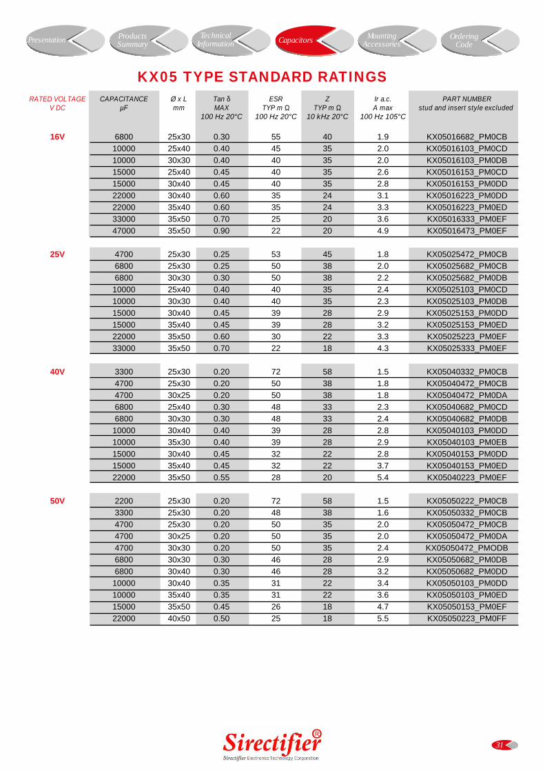
KX05 TYPE STANDARD RATINGS
Presentation Capacitors MountingAccessories
OrderingCode
ProductsSummary
TechnicalInformation
RATED VOLTAGE CAPACITANCE Ø x L Tan δ ESR Z Ir a.c. PART NUMBERV DC µF mm MAX TYP m Ω TYP m Ω A max stud and insert style excluded
100 Hz 20°C 100 Hz 20°C 10 kHz 20°C 100 Hz 105°C
63V 2200 25x30 0.15 79 60 1.5 KX05063222_PM0CB
3300 25x40 0.15 50 40 2.3 KX05063332_PM0CD
3300 30x30 0.15 50 40 2.1 KX05063332_PM0DB
4700 30x30 0.20 40 29 2.4 KX05063472_PM0DB
4700 30x40 0.20 40 29 2.8 KX05063472_PM0DD
6800 30x40 0.30 35 25 3.0 KX05063682_PM0DD
6800 35x40 0.30 35 25 4.4 KX05063682_PM0ED
10000 35x50 0.35 30 23 5.3 KX05063103_PM0EF
100V 1000 25x30 0.10 127 100 1.7 KX05100102_PM0CB
1000 30x25 0.10 127 100 1.7 KX05100102_PM0DA
1500 25x40 0.12 105 82 2.0 KX05100152_PM0CD
1500 30x30 0.12 105 82 1.8 KX05100152_PM0DB
2200 30x40 0.15 71 60 2.7 KX05100222_PM0DD
3300 30x50 0.15 48 39 3.0 KX05100332_PM0DF
3300 35x40 0.15 48 39 3.3 KX05100332_PM0ED
4700 35x50 0.20 33 26 4.4 KX05100472_PM0EF
5600 40x50 0.20 33 24 4.8 KX05100562_PM0FF
6800 40x50 0.20 33 24 4.9 KX05100682_PM0FF
200V 220 22x30 0.10 440 340 0.9 KX05200221_PM0BB
220 25x30 0.10 440 340 1.1 KX05200221_PM0CB
330 22x30 0.10 240 133 1.1 KX05200331_PM0BB
330 25x30 0.10 240 133 1.2 KX05200331_PM0CB
470 25x30 0.10 169 98 3.0 KX05200471_PM0CB
470 30x30 0.10 169 98 1.6 KX05200471_PM0DB
680 25x40 0.10 145 87 1.7 KX05200681_PM0CD
680 30x40 0.10 145 87 2.0 KX05200681_PM0DD
1000 30x40 0.10 95 63 2.1 KX05200102_PM0DD
1000 35x40 0.10 95 63 2.4 KX05200102_PM0ED
1500 30x50 0.10 70 41 2.4 KX05200152_PM0DF
1500 35x50 0.10 70 41 2.6 KX05200152_PM0EF
2200 35x50 0.12 45 33 2.8 KX05200222_PM0EF
250V 100 25x30 0.10 950 730 0.7 KX05250101_PM0CB
150 25x30 0.10 530 290 0.7 KX05250151_PM0CB
220 25x30 0.10 370 240 0.9 KX05250221_PM0CB
330 30x30 0.10 260 153 1.2 KX05250331_PM0DB
470 25x40 0.10 180 110 1.5 KX05250471_PM0CD
470 30x30 0.10 180 110 1.5 KX05250471_PM0DB
680 35x40 0.10 145 95 1.8 KX05250681_PM0ED
1000 35x50 0.10 98 65 2.6 KX05250102_PM0EF
1500 35x50 0.12 75 43 2.8 KX05250152_PM0EF
32
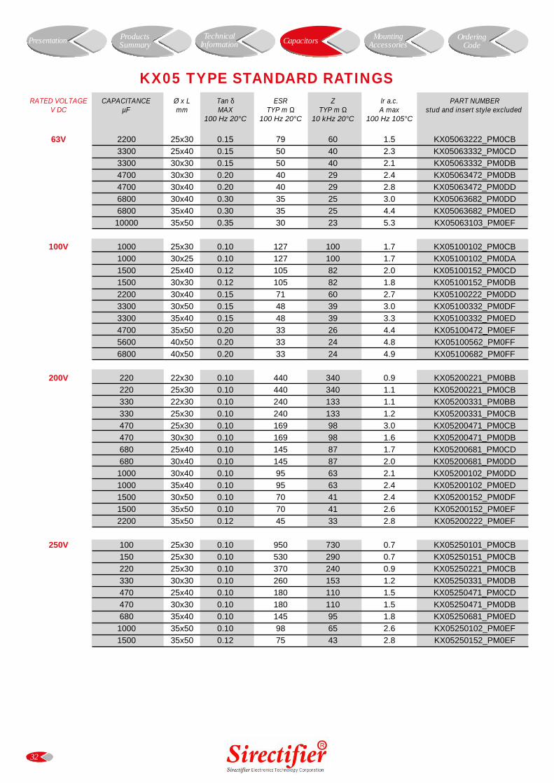
KX05 TYPE STANDARD RATINGS
Presentation Capacitors MountingAccessories
OrderingCode
ProductsSummary
TechnicalInformation
RATED VOLTAGE CAPACITANCE Ø x L Tan δ ESR Z Ir a.c. PART NUMBERV DC µF mm MAX TYP m Ω TYP m Ω A max stud and insert style excluded
100 Hz 20°C 100 Hz 20°C 10 kHz 20°C 100 Hz 105°C
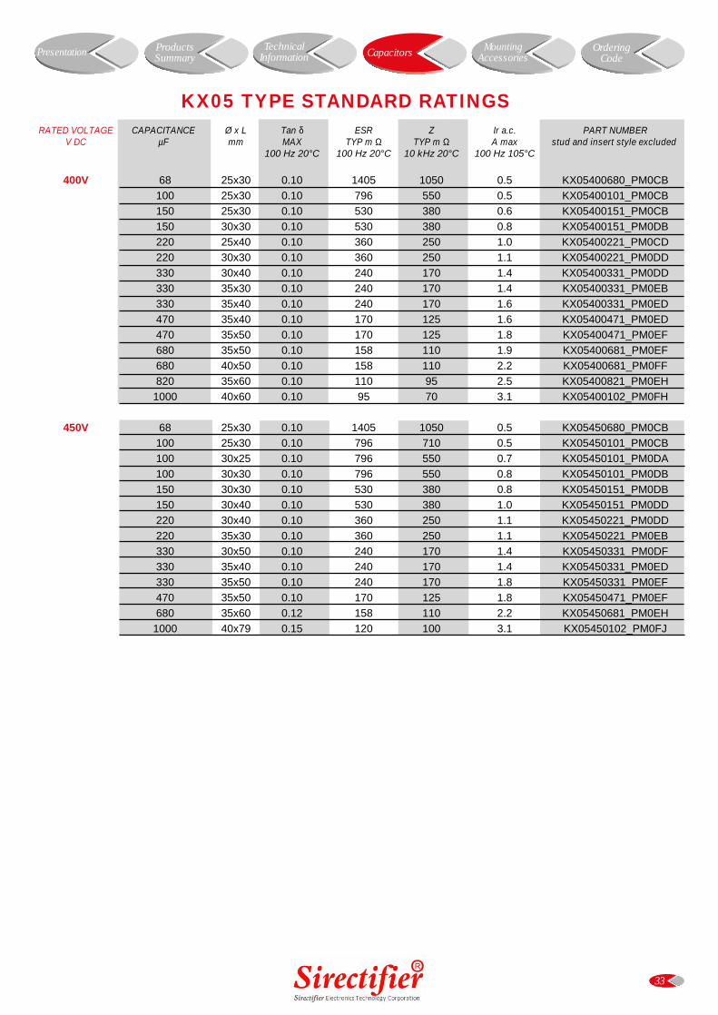
400V 68 25x30 0.10 1405 1050 0.5 KX05400680_PM0CB
100 25x30 0.10 796 550 0.5 KX05400101_PM0CB
150 25x30 0.10 530 380 0.6 KX05400151_PM0CB
150 30x30 0.10 530 380 0.8 KX05400151_PM0DB
220 25x40 0.10 360 250 1.0 KX05400221_PM0CD
220 30x30 0.10 360 250 1.1 KX05400221_PM0DD
330 30x40 0.10 240 170 1.4 KX05400331_PM0DD
330 35x30 0.10 240 170 1.4 KX05400331_PM0EB
330 35x40 0.10 240 170 1.6 KX05400331_PM0ED
470 35x40 0.10 170 125 1.6 KX05400471_PM0ED
470 35x50 0.10 170 125 1.8 KX05400471_PM0EF
680 35x50 0.10 158 110 1.9 KX05400681_PM0EF
680 40x50 0.10 158 110 2.2 KX05400681_PM0FF
820 35x60 0.10 110 95 2.5 KX05400821_PM0EH
1000 40x60 0.10 95 70 3.1 KX05400102_PM0FH
450V 68 25x30 0.10 1405 1050 0.5 KX05450680_PM0CB
100 25x30 0.10 796 710 0.5 KX05450101_PM0CB
100 30x25 0.10 796 550 0.7 KX05450101_PM0DA
100 30x30 0.10 796 550 0.8 KX05450101_PM0DB
150 30x30 0.10 530 380 0.8 KX05450151_PM0DB
150 30x40 0.10 530 380 1.0 KX05450151_PM0DD
220 30x40 0.10 360 250 1.1 KX05450221_PM0DD
220 35x30 0.10 360 250 1.1 KX05450221_PM0EB
330 30x50 0.10 240 170 1.4 KX05450331_PM0DF
330 35x40 0.10 240 170 1.4 KX05450331_PM0ED
330 35x50 0.10 240 170 1.8 KX05450331_PM0EF
470 35x50 0.10 170 125 1.8 KX05450471_PM0EF
680 35x60 0.12 158 110 2.2 KX05450681_PM0EH
1000 40x79 0.15 120 100 3.1 KX05450102_PM0FJ
33
KX05 TYPE STANDARD RATINGS
Presentation Capacitors MountingAccessories
OrderingCode
ProductsSummary
TechnicalInformation
34
KX06 TYPE
• Surge-proof electrolytic capacitor in aluminium can withinsulation sleeve.
• Safety vent at bottom case or aside case.• Snap in terminals for PCB mounting.
Very high CV for unit volume with low ESR.High ripple current in small dimensions case size.Operation up to 105°C permissible.
APPLICATIONSProfessional switch mode power supplies. Professional power electronics.
SPECIFICATIONSGENERAL CHARACTERISTICS
Temperature Range Operating: -40°C +85°C [Environmental classification 40/85/56 IEC-68]Storage : Preferably below +25°C, not exceeding +40°C
Rated Voltage Range (Vr) from 16V to 400V DC
Surge Voltage (Vp) Vp = 1.15 Vr (Vr ² 250V DC)Vp = 1.10 Vr (Vr > 250V DC)
Rated Capacitance Range from 68 µF to 33,000 µF
Capacitance Tolerance ±20% at 100 Hz, 20°C [M class IEC-62]
Leakage Current (IL) max IL= 0.006 Cr Vr + 4 µA Sirectifier product limit : IL= 0.003 Cr Vr
(mA, 5 min, 20°C) At 85°C max IL = 0.04 Cr Vr µA
Ripple current (Ir) Refer to table at 85°C and 100Hz For different temperature and frequency multiplier must be used as follows:
FREQUENCY 50Hz 100Hz 500 Hz 1000Hz >10kHz
MULTIPLIER (0-25V Vr DC) 0.91 1.0 1.15 1.15 1.2
MULTIPLIER (40-100V Vr DC) 0.88 1.0 1.35 1.40 1.45
MULTIPLIER (160-450V Vr DC) 0.88 1.0 1.45 1.50 1.55
AMBIENT TEMP. 35°C 45°C 55°C 65°C 75°C 85°C
MULTIPLIER 2.2 2.1 1.8 1.6 1.4 1.0
Maximum internal temperature 98°C
Insulation Resistance At 100V DC for 1 min is >100 MΩ across insulating sleeve and terminals.
Vibration Resistance Frequency range: 10 Hz to 500 Hz, amplitude 0.75 mmmax acceleration 10g for 3x2 h
Life test After 2,000 hours application of rated voltage at 85°C Cap change ² 20%capacitors meet characteristics aside tan δ ² 200%
Leakage current (IL) < initial limitImpedance (Z) ² 200%
Shelf life After leaving capacitors under no load for 500 hours at 85°C, Cap change ² ±15%when restored at 20°C meet specifications aside tan δ ² 150%
Leakage current (IL) < initial limit
Useful life > 200,000 h at 40°C> 5,000 h at 85°C
Failure percentage ² 1% (during useful life) Failure rate ² 40 fit (40 10-9/h (Vr ² 160V DC)
² 70 fit (70 10-9/h (Vr > 160V DC)
Self inductance Approx. 20 nH
Reference standards CECC 30.301 - IEC 60384-4 LONG LIFE GRADE
Presentation Capacitors MountingAccessories
OrderingCode
ProductsSummary
TechnicalInformation
35
USEFUL LIFE KX06
0.5
1.0
1.5
2.0
2.5
3.0
35 40 45 50 55 60 65 70 75 80 85 90 95Temperature °C
I r ac
/ I r
ac 8
5°C
250,0
00h
100,0
00h
50,00
0h
20,00
0h
10,00
0h
5,000
h
Dimensions in mm.
Circuit boardhole dimensions
H ± 2
6.3
10
Ø ± 0.5
10±0.1
(only Ø 40 mm.)
H
6.3 ± 1
40 ± 1
BLANK BLANK
22.5
4-Ø2 hole
60° 60°Circuit boardhole dimensions
Sirectifier Sirectifier
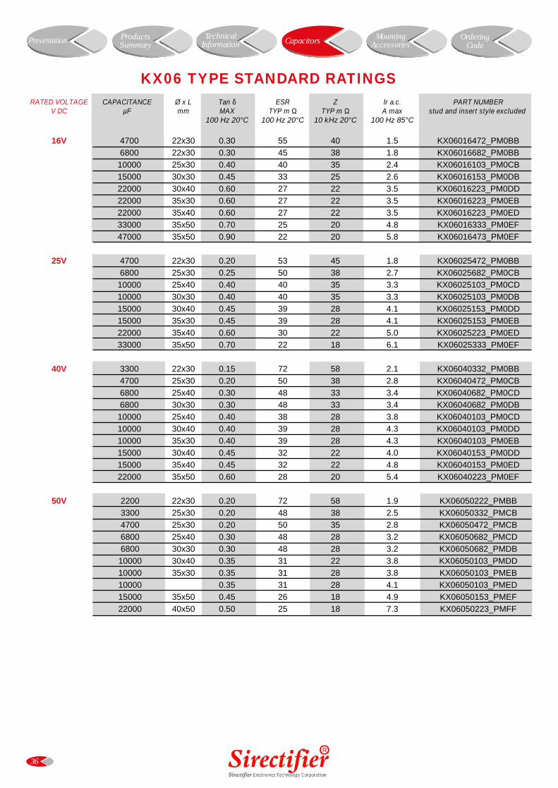
RATED VOLTAGE CAPACITANCE Ø x L Tan δ ESR Z Ir a.c. PART NUMBERV DC µF mm MAX TYP m Ω TYP m Ω A max stud and insert style excluded
100 Hz 20°C 100 Hz 20°C 10 kHz 20°C 100 Hz 85°C
16V 4700 22x30 0.30 55 40 1.5 KX06016472_PM0BB
6800 22x30 0.30 45 38 1.8 KX06016682_PM0BB
10000 25x30 0.40 40 35 2.4 KX06016103_PM0CB
15000 30x30 0.45 33 25 2.6 KX06016153_PM0DB
22000 30x40 0.60 27 22 3.5 KX06016223_PM0DD
22000 35x30 0.60 27 22 3.5 KX06016223_PM0EB
22000 35x40 0.60 27 22 3.5 KX06016223_PM0ED
33000 35x50 0.70 25 20 4.8 KX06016333_PM0EF
47000 35x50 0.90 22 20 5.8 KX06016473_PM0EF
25V 4700 22x30 0.20 53 45 1.8 KX06025472_PM0BB
6800 25x30 0.25 50 38 2.7 KX06025682_PM0CB
10000 25x40 0.40 40 35 3.3 KX06025103_PM0CD
10000 30x30 0.40 40 35 3.3 KX06025103_PM0DB
15000 30x40 0.45 39 28 4.1 KX06025153_PM0DD
15000 35x30 0.45 39 28 4.1 KX06025153_PM0EB
22000 35x40 0.60 30 22 5.0 KX06025223_PM0ED
33000 35x50 0.70 22 18 6.1 KX06025333_PM0EF
40V 3300 22x30 0.15 72 58 2.1 KX06040332_PM0BB
4700 25x30 0.20 50 38 2.8 KX06040472_PM0CB
6800 25x40 0.30 48 33 3.4 KX06040682_PM0CD
6800 30x30 0.30 48 33 3.4 KX06040682_PM0DB
10000 25x40 0.40 38 28 3.8 KX06040103_PM0CD
10000 30x40 0.40 39 28 4.3 KX06040103_PM0DD
10000 35x30 0.40 39 28 4.3 KX06040103_PM0EB
15000 30x40 0.45 32 22 4.0 KX06040153_PM0DD
15000 35x40 0.45 32 22 4.8 KX06040153_PM0ED
22000 35x50 0.60 28 20 5.4 KX06040223_PM0EF
50V 2200 22x30 0.20 72 58 1.9 KX06050222_PMBB
3300 25x30 0.20 48 38 2.5 KX06050332_PMCB
4700 25x30 0.20 50 35 2.8 KX06050472_PMCB
6800 25x40 0.30 48 28 3.2 KX06050682_PMCD
6800 30x30 0.30 48 28 3.2 KX06050682_PMDB
10000 30x40 0.35 31 22 3.8 KX06050103_PMDD
10000 35x30 0.35 31 28 3.8 KX06050103_PMEB
10000 0.35 31 28 4.1 KX06050103_PMED
15000 35x50 0.45 26 18 4.9 KX06050153_PMEF
22000 40x50 0.50 25 18 7.3 KX06050223_PMFF
36
KX06 TYPE STANDARD RATINGS
Presentation Capacitors MountingAccessories
OrderingCode
ProductsSummary
TechnicalInformation
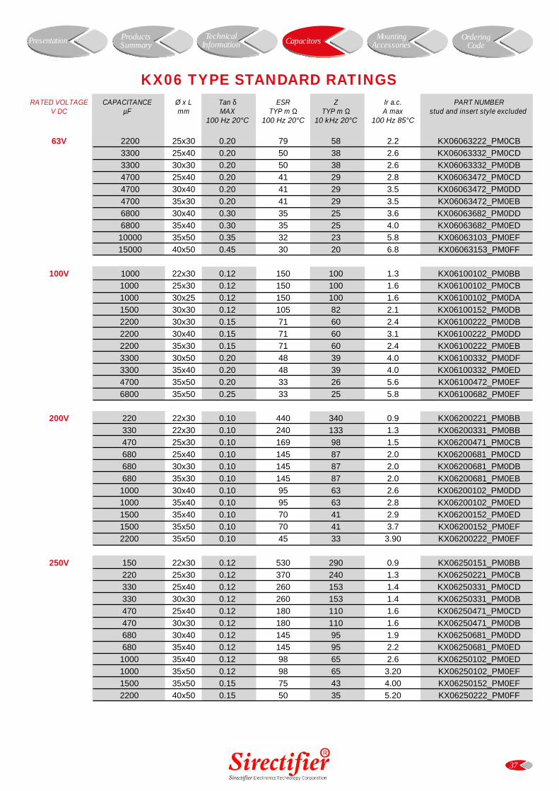
RATED VOLTAGE CAPACITANCE Ø x L Tan δ ESR Z Ir a.c. PART NUMBERV DC µF mm MAX TYP m Ω TYP m Ω A max stud and insert style excluded
100 Hz 20°C 100 Hz 20°C 10 kHz 20°C 100 Hz 85°C
63V 2200 25x30 0.20 79 58 2.2 KX06063222_PM0CB
3300 25x40 0.20 50 38 2.6 KX06063332_PM0CD
3300 30x30 0.20 50 38 2.6 KX06063332_PM0DB
4700 25x40 0.20 41 29 2.8 KX06063472_PM0CD
4700 30x40 0.20 41 29 3.5 KX06063472_PM0DD
4700 35x30 0.20 41 29 3.5 KX06063472_PM0EB
6800 30x40 0.30 35 25 3.6 KX06063682_PM0DD
6800 35x40 0.30 35 25 4.0 KX06063682_PM0ED
10000 35x50 0.35 32 23 5.8 KX06063103_PM0EF
15000 40x50 0.45 30 20 6.8 KX06063153_PM0FF
100V 1000 22x30 0.12 150 100 1.3 KX06100102_PM0BB
1000 25x30 0.12 150 100 1.6 KX06100102_PM0CB
1000 30x25 0.12 150 100 1.6 KX06100102_PM0DA
1500 30x30 0.12 105 82 2.1 KX06100152_PM0DB
2200 30x30 0.15 71 60 2.4 KX06100222_PM0DB
2200 30x40 0.15 71 60 3.1 KX06100222_PM0DD
2200 35x30 0.15 71 60 2.4 KX06100222_PM0EB
3300 30x50 0.20 48 39 4.0 KX06100332_PM0DF
3300 35x40 0.20 48 39 4.0 KX06100332_PM0ED
4700 35x50 0.20 33 26 5.6 KX06100472_PM0EF
6800 35x50 0.25 33 25 5.8 KX06100682_PM0EF
200V 220 22x30 0.10 440 340 0.9 KX06200221_PM0BB
330 22x30 0.10 240 133 1.3 KX06200331_PM0BB
470 25x30 0.10 169 98 1.5 KX06200471_PM0CB
680 25x40 0.10 145 87 2.0 KX06200681_PM0CD
680 30x30 0.10 145 87 2.0 KX06200681_PM0DB
680 35x30 0.10 145 87 2.0 KX06200681_PM0EB
1000 30x40 0.10 95 63 2.6 KX06200102_PM0DD
1000 35x40 0.10 95 63 2.8 KX06200102_PM0ED
1500 35x40 0.10 70 41 2.9 KX06200152_PM0ED
1500 35x50 0.10 70 41 3.7 KX06200152_PM0EF
2200 35x50 0.10 45 33 3.90 KX06200222_PM0EF
250V 150 22x30 0.12 530 290 0.9 KX06250151_PM0BB
220 25x30 0.12 370 240 1.3 KX06250221_PM0CB
330 25x40 0.12 260 153 1.4 KX06250331_PM0CD
330 30x30 0.12 260 153 1.4 KX06250331_PM0DB
470 25x40 0.12 180 110 1.6 KX06250471_PM0CD
470 30x30 0.12 180 110 1.6 KX06250471_PM0DB
680 30x40 0.12 145 95 1.9 KX06250681_PM0DD
680 35x40 0.12 145 95 2.2 KX06250681_PM0ED
1000 35x40 0.12 98 65 2.6 KX06250102_PM0ED
1000 35x50 0.12 98 65 3.20 KX06250102_PM0EF
1500 35x50 0.15 75 43 4.00 KX06250152_PM0EF
2200 40x50 0.15 50 35 5.20 KX06250222_PM0FF
37
KX06 TYPE STANDARD RATINGS
Presentation Capacitors MountingAccessories
OrderingCode
ProductsSummary
TechnicalInformation
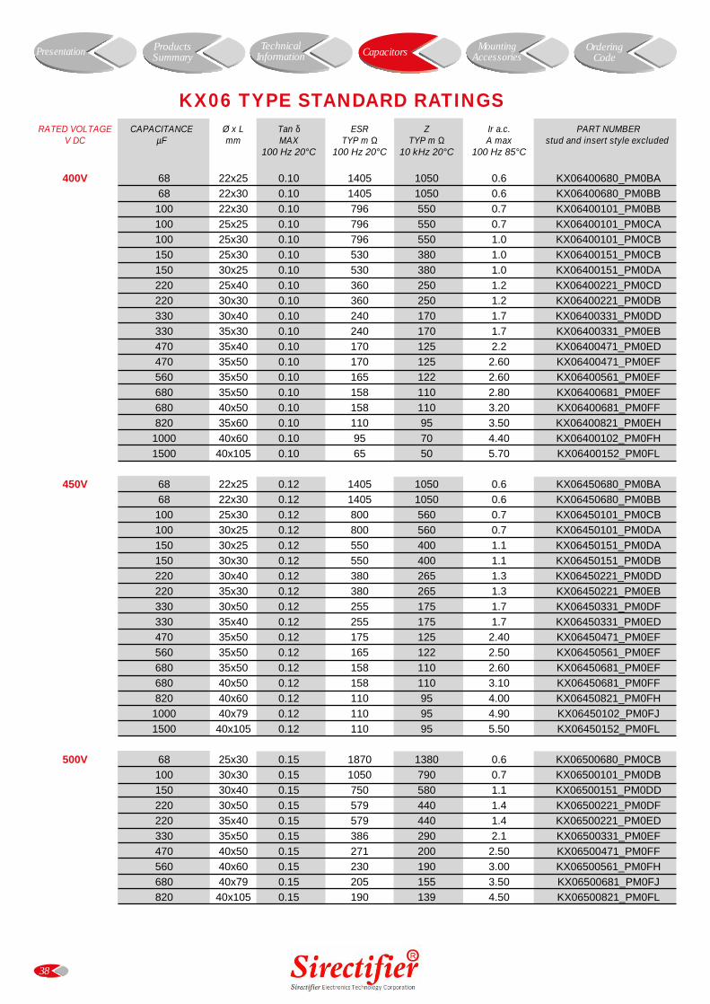
RATED VOLTAGE CAPACITANCE Ø x L Tan δ ESR Z Ir a.c. PART NUMBERV DC µF mm MAX TYP m Ω TYP m Ω A max stud and insert style excluded
100 Hz 20°C 100 Hz 20°C 10 kHz 20°C 100 Hz 85°C
400V 68 22x25 0.10 1405 1050 0.6 KX06400680_PM0BA
68 22x30 0.10 1405 1050 0.6 KX06400680_PM0BB
100 22x30 0.10 796 550 0.7 KX06400101_PM0BB
100 25x25 0.10 796 550 0.7 KX06400101_PM0CA
100 25x30 0.10 796 550 1.0 KX06400101_PM0CB
150 25x30 0.10 530 380 1.0 KX06400151_PM0CB
150 30x25 0.10 530 380 1.0 KX06400151_PM0DA
220 25x40 0.10 360 250 1.2 KX06400221_PM0CD
220 30x30 0.10 360 250 1.2 KX06400221_PM0DB
330 30x40 0.10 240 170 1.7 KX06400331_PM0DD
330 35x30 0.10 240 170 1.7 KX06400331_PM0EB
470 35x40 0.10 170 125 2.2 KX06400471_PM0ED
470 35x50 0.10 170 125 2.60 KX06400471_PM0EF
560 35x50 0.10 165 122 2.60 KX06400561_PM0EF
680 35x50 0.10 158 110 2.80 KX06400681_PM0EF
680 40x50 0.10 158 110 3.20 KX06400681_PM0FF
820 35x60 0.10 110 95 3.50 KX06400821_PM0EH
1000 40x60 0.10 95 70 4.40 KX06400102_PM0FH
1500 40x105 0.10 65 50 5.70 KX06400152_PM0FL
450V 68 22x25 0.12 1405 1050 0.6 KX06450680_PM0BA
68 22x30 0.12 1405 1050 0.6 KX06450680_PM0BB
100 25x30 0.12 800 560 0.7 KX06450101_PM0CB
100 30x25 0.12 800 560 0.7 KX06450101_PM0DA
150 30x25 0.12 550 400 1.1 KX06450151_PM0DA
150 30x30 0.12 550 400 1.1 KX06450151_PM0DB
220 30x40 0.12 380 265 1.3 KX06450221_PM0DD
220 35x30 0.12 380 265 1.3 KX06450221_PM0EB
330 30x50 0.12 255 175 1.7 KX06450331_PM0DF
330 35x40 0.12 255 175 1.7 KX06450331_PM0ED
470 35x50 0.12 175 125 2.40 KX06450471_PM0EF
560 35x50 0.12 165 122 2.50 KX06450561_PM0EF
680 35x50 0.12 158 110 2.60 KX06450681_PM0EF
680 40x50 0.12 158 110 3.10 KX06450681_PM0FF
820 40x60 0.12 110 95 4.00 KX06450821_PM0FH
1000 40x79 0.12 110 95 4.90 KX06450102_PM0FJ
1500 40x105 0.12 110 95 5.50 KX06450152_PM0FL
500V 68 25x30 0.15 1870 1380 0.6 KX06500680_PM0CB
100 30x30 0.15 1050 790 0.7 KX06500101_PM0DB
150 30x40 0.15 750 580 1.1 KX06500151_PM0DD
220 30x50 0.15 579 440 1.4 KX06500221_PM0DF
220 35x40 0.15 579 440 1.4 KX06500221_PM0ED
330 35x50 0.15 386 290 2.1 KX06500331_PM0EF
470 40x50 0.15 271 200 2.50 KX06500471_PM0FF
560 40x60 0.15 230 190 3.00 KX06500561_PM0FH
680 40x79 0.15 205 155 3.50 KX06500681_PM0FJ
820 40x105 0.15 190 139 4.50 KX06500821_PM0FL
38
KX06 TYPE STANDARD RATINGS
Presentation Capacitors MountingAccessories
OrderingCode
ProductsSummary
TechnicalInformation
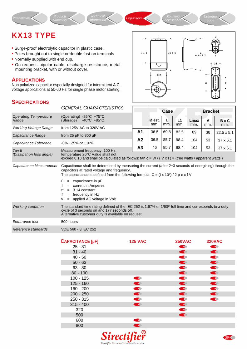
39
Case Bracket
Ø est.mm.
36.5
36.5
46
Lmm.
69.8
85.7
85.7
L1mm.
82.5
98.4
98.4
Lmaxmm.
89
104
104
Amm.
38
53
53
B x Cmm.
22.5 x 5.1
37 x 6.1
37 x 6.1
A1
A2
A3
28
BA
C
Lmax ± 1
L1 ± 1L ± 1
Ø D
SPECIFICATIONSGENERAL CHARACTERISTICS
Operating Temperature (Operating) -25°C +75°C Range (Storage) -40°C +85°C
Working Voltage Range from 125V AC to 320V AC
Capacitance Range from 25 µF to 800 µF
Capacitance Tolerance -0% +25% or ±10%
Tan δ Measurement frequency; 100 Hz, (Dissipation loss angle) temperature 20°C Value shall not
exceed 0.10 and shall be calculated as follows: tan δ = W / ( V x I ) = (true watts / apparent watts )
Capacitance Measurement Capacitance shall be determined by measuring the current (after 2÷3 seconds of energising) through thecapacitors at rated voltage and frequency.The capacitance is defined from the following formula: C = (I x 106) / 2 p π x f V
C = capacitance in µFI = current in Amperesπ = 3.14 constantf = frequency in HzV = applied AC voltage in Volt
Working condition The standard time rating defined of the IEC 252 is 1.67% or 1/60th full time and corresponds to a dutycycle of 3 seconds on and 177 seconds off.Alternative customer duty is available on request.
Endurance test 500 hours
Reference standards VDE 560 - 8 IEC 252
CAPACITANCE [µF] 125 VAC 250VAC 320VAC25 - 3131 - 4040 - 5050 - 6363 - 80
80 - 100100 - 125125 - 160160 - 200200 - 250250 - 315315 - 400
320500600800
• Surge-proof electrolytic capacitor in plastic case.• Poles brought out to single or double fast-on terminals• Normally supplied with end cup.• On request: bipolar cable, discharge resistance, metal
mounting bracket, with or without cover.
APPLICATIONSNon polarized capacitor especially designed for intermittent A.C.voltage applications at 50-60 Hz for single phase motor starting.
KX13 TYPE
Presentation Capacitors MountingAccessories
OrderingCode
ProductsSummary
TechnicalInformation
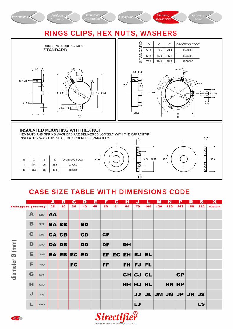
40
RINGS CLIPS, HEX NUTS, WASHERS
INSULATED MOUNTING WITH HEX NUTHEX NUTS AND SPRING WASHERS ARE DELIVERED LOOSELY WITH THE CAPACITOR.INSULATION WASHERS SHALL BE ORDERED SEPARATELY. 2.5
Ø A Ø CM A B C ORDERING CODE
8 8.4 25 18.5 130001
12 12.5 35 18.5 130002
ORDERING CODE 1635000STANDARD
56.5
9
4
466.5
1.5
35 - 0 + 0.5
4
5.511.2
30°
5
0.8
19
Ø 4.25
14 5
ST
AN
DA
RD D C E ORDERING CODE
50.8 63.5 73.4 1650000
63.5 76.0 86.1 1664000
76.0 89.0 98.6 1676000
120°
15°
15
+0.5 - 0
D 12.5
10.5
4.5
10.5
E
CE
7
19 9.5
Ø 50.8
28.5
CASE SIZE TABLE WITH DIMENSIONS CODE
Presentation CapacitorsTechnicalInformation
ProductsSummary
OrderingCode
MountingAccessories
3
Ø A Ø C Ø B
1.3
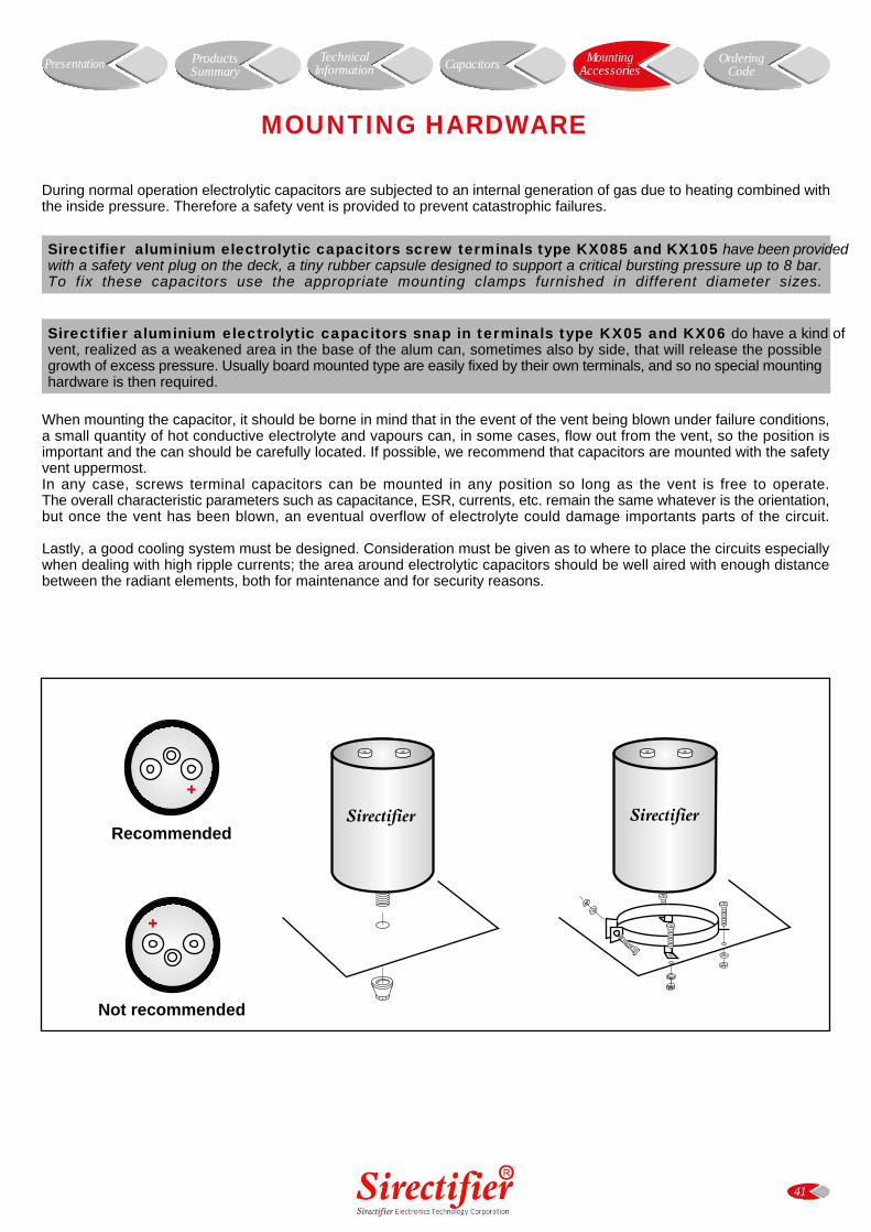
41
During normal operation electrolytic capacitors are subjected to an internal generation of gas due to heating combined withthe inside pressure. Therefore a safety vent is provided to prevent catastrophic failures.
When mounting the capacitor, it should be borne in mind that in the event of the vent being blown under failure conditions,a small quantity of hot conductive electrolyte and vapours can, in some cases, flow out from the vent, so the position isimportant and the can should be carefully located. If possible, we recommend that capacitors are mounted with the safetyvent uppermost.In any case, screws terminal capacitors can be mounted in any position so long as the vent is free to operate.The overall characteristic parameters such as capacitance, ESR, currents, etc. remain the same whatever is the orientation,but once the vent has been blown, an eventual overflow of electrolyte could damage importants parts of the circuit.
Lastly, a good cooling system must be designed. Consideration must be given as to where to place the circuits especiallywhen dealing with high ripple currents; the area around electrolytic capacitors should be well aired with enough distancebetween the radiant elements, both for maintenance and for security reasons.
Sirectifier aluminium electrolytic capacitors screw terminals type KX085 and KX105 have been providedwith a safety vent plug on the deck, a tiny rubber capsule designed to support a critical bursting pressure up to 8 bar.To fix these capacitors use the appropriate mounting clamps furnished in different diameter sizes.
Sirectifier aluminium electrolytic capacitors snap in terminals type KX05 and KX06 do have a kind ofvent, realized as a weakened area in the base of the alum can, sometimes also by side, that will release the possiblegrowth of excess pressure. Usually board mounted type are easily fixed by their own terminals, and so no special mountinghardware is then required.
MOUNTING HARDWARE
Presentation CapacitorsTechnicalInformation
ProductsSummary
OrderingCode
MountingAccessories
Recommended
Not recommended
Sirectifier Sirectifier
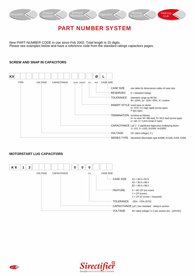
42
PART NUMBER SYSTEM
New PART-NUMBER CODE in use since Feb 2002. Total length is 15 digits.Please see examples below and have a reference code from the standard ratings capacitors pages.
SCREW AND SNAP IN CAPACITORS
DIGIT 1 2 3 4 5 6 7 8 9 10 11 12 13 14 15
KX Ø L
TYPE VOLTAGE CAPACITANCE TERM INSERT TOL RES CASE SIZE
CASE SIZE see table for dimensions codes of case size
RESERVED 0 = standard ratings
TOLERANCE tolerance range as IEC62M= ±20%, Q= -10% +30%, X= custom
INSERT STYLE insert type on decks0= STD, H= High ripple (screw type)P (pin type)
TERMINATION terminal as follows:0= no stud. M= M8 stud, S= M12 stud (screw type)o= std, 4= 4 pins (snap in type)
CAPACITANCE [ µF ] - 2 significant digits plus multiplying factor1= x10, 2= x100, 3x1000, 4x10000
VOLTAGE DC rated voltage [ V ]
SERIES TYPE Aluminium Electrolytic type KX085, KX105, KX05, KX06
K X 1 3 0 0 0
VOLTAGE CAPACITANCE TOL CASE SIZE
CASE SIZE A1 = 36.5 x 82.5A2 = 36.5 x 98.4 B2 = 46.0 x 98.4
FEATURE 0 = NO CP (no cover)1 = CP (cover)2 = CP ST (cover + brascket)
TOLERANCE -25% +75% (STD)
CAPACITANCE [ µF ] see standard rating in section
VOLTAGE AC rated voltage [ V ] see section (ex.: 125VAC)
MOTORSTART LUG CAPACITORS
Presentation ProductsSummary CapacitorsTechnical
InformationOrdering
CodeMounting
Accessories
SIZE CASE CODE APPROX UNIT WEIGHT QTY / BOX BOX DIMENSIONS
ØxL [mm] grams nr cm
KX085 K02SCREW TYPE 35x51 EG 80 60 36 x 25 x 6
35x60 EH 70 60 36 x 25 x 8
35x79 EJ 110 60 36 x 25 x 8
51x60 GH 110 42 38.5 x 38.5 x 14
51x79 GJ 200 42 38.5 x 38.5 x 14
51x105 GL 260 42 38.5 x 38.5 x 14
51x143 GP 370 42 38.5 x 38.5 x 18
63x60 HH 240 25 38.5 x 38.5 x 14
63x79 HJ 280 25 38.5 x 38.5 x 14
63x105 HL 420 25 38.5 x 38.5 x 14
63x143 HP 540 25 38.5 x 38.5 x 18
76x79 JJ 450 16 38.5 x 38.5 x 14
76x105 JL 520 16 38.5 x 38.5 x 14
76x120 JM 790 16 38.5 x 38.5 x 18
76x130 JN 850 16 38.5 x 38.5 x 18
76x143 JP 940 16 38.5 x 38.5 x 18
76x220 JS 1540 16 38.5 x 38.5 x 25
90x79 LJ 510 9 38.5 x 38.5 x 14
90x220 LS 1880 9 38.5 x 38.5 x 25
KX05-KX06SNAP-IN TYPE 22x25 BA 15 160 36 x 25 x 6
22x30 BB 19 160 36 x 25 x 6
22x40 BD 24 160 36 x 25 x 6
25x25 CA 16 126 36 x 25 x 6
25x30 CB 21 126 36 x 25 x 6
25x40 CD 30 126 36 x 25 x 6
25x50 CF 38 126 36 x 25 x 6
30x25 DA 24 77 36 x 25 x 6
30x30 DB 27 77 36 x 25 x 6
30x40 DD 38 77 36 x 25 x 6
30x50 DF 55 77 36 x 25 x 6
35x25 EA 42 60 36 x 25 x 6
35x30 EB 45 60 36 x 25 x 6
35x35 EC 50 60 36 x 25 x 6
35x40 ED 62 60 36 x 25 x 6
35x50 EF 78 60 36 x 25 x 6
35x60 EH 88 60 36 x 25 x 8
40x50 FF 98 45 36 x 25 x 6
40x60 FH 117 45 36 x 25 x 8
40x79 FJ 138 45 36 x 25 x 8
40x105 FL 181 12 36 x 25 x 6
43
CAPACITORS WEIGHT TABLE
Presentation ProductsSummary
CapacitorsTechnicalInformation
OrderingCode
MountingAccessories
KX085KX105SCREW TYPE
GENERAL WARNING
44
Information and data contained in the section “Technical Information” must be considered as a completing part of each family type of capacitor.Before using a Sirectifier capacitor in any application, please read carefully the related specifications included in the catalogue.An improper installation or not respecting parameters limits might cause damage to the components, their characteristics modification and a decrease of their reliability and useful life.Products manufactured by Sirectifier are made with maximum care, in order to result free of defects in design, materials and workmanship, according with adequate specifications and international standard requirements.
DISCLAIMERCooperation between Customers and Sirectifier is basically precious in order to solve problems or when a failure occurs. In case of complaint you might have, please forward the following information along with an immediate communication of the failure.Only upon previous agreement with Sirectifier, you could send a detailed description of failure, indicating operative condition and type of application, number of defective pieces, eventually expressed in percent on whole quantity used. It is mandatory to know the original batch of goods as printed on the capacitor sleeve or labeled on the box, also let us know the delivery date and others relevant data from the billing documents. Samples of defective products should be sent to Sirectifier for analysis, packed in order to prevent additional damages different from the ones detected.Data sheets specifications are referred to a fairly large number of components and do not constitute a guarantee of characteristics or properties in the legal sense.However, agreement on these specifications does not mean that the Customer may not claim for replacement of individual defective capacitors within the terms of delivery; Sirectifier will not assume any further liability beyond the replacement of defective capacitors.This applies in particular to any further consequences of component failure as better specified further in this section.A single failure among a delivered batch of capacitors should not be meaningful of poor reliability of the whole production batch, but should be understood to have reached incidentally the end of life within the failure rate defined for each series type.
NO LIABILITY FOR CONSEQUENTIAL DAMAGESSirectifier liability shall be limited to only replacement of repairing of goods, free of charge, after aknowledge of received notification by customer.Sirectifier is not responsible for any possible damage to persons or things, of any kind, derived from improper installation, use of application of its products.Also, the producer shall not be liable for any defect due to accident, fair wear and tear, negligent use, tampering, improper handling and shipment, operation and storage or any other default on the parts of any person other then Sirectifier.To the maximum extent permitted by above statements, in no event shall Sirectifier or its referred dealers be liable for any damages whatsoever (including without limitation, special, incidental, consequential, or indirect damages for personal injury, loss of business profits, business interruption or any pecuniary loss) arising out of the use or inability to use Sirectifier products.In the case of any product liability claim from third parties against Sirectifier, not falling within Sirectifier liability, Customer or Buyer should hold Sirectifier harmless.