Embed Size (px)
Citation preview
PATENTS
16Sealing Technology November 2005
Directly molded valve seal for accumulator
General arrangement showingthe position of the accumulatorseal described in WO 2005/083307.
Cylinder-head gasket with an elastomer sealing layerApplicant: Federal-Mogul Sealing
Systems GmbH, GermanyThis invention relates to an auto-motive cylinder-head gasket. Toprotect the gasket from ingress ofpotentially corrosive liquids, it hasan elastomer seal (2) molded on theperiphery. The elastomer layer is
also electrically insulating, in orderto protect the functional metal lay-ers (4) of the gasket from contactcorrosion.Patent number: WO 2005/080834Inventors: B. Lambert, A. Retiere
and R. FlemmingPublication date: 1 September 2005
The cylinder-head gasket from WO 2005/080834, with an electricallyinsulating elastomer seal to protect the gasket from corrosion.
Vibration damper gasket for vehicle steering columns
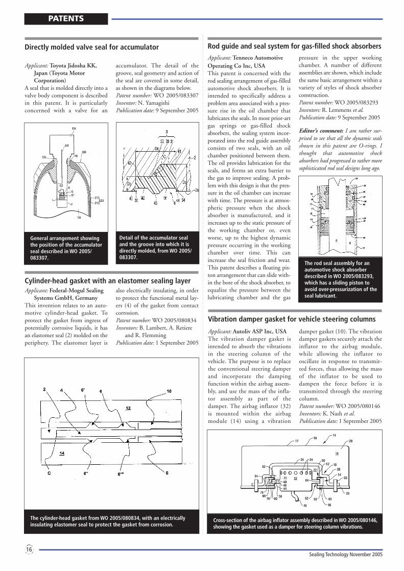
Applicant: Autoliv ASP Inc, USAThe vibration damper gasket isintended to absorb the vibrationsin the steering column of thevehicle. The purpose is to replacethe conventional steering damperand incorporate the dampingfunction within the airbag assem-bly, and use the mass of the infla-tor assembly as part of thedamper. The airbag inflator (32)is mounted within the airbagmodule (14) using a vibration
damper gasket (10). The vibrationdamper gaskets securely attach theinflator to the airbag module,while allowing the inflator tooscillate in response to transmit-ted forces, thus allowing the massof the inflator to be used todampen the force before it istransmitted through the steeringcolumn.Patent number: WO 2005/080146Inventors: K. Nash et al.Publication date: 1 September 2005
Cross-section of the airbag inflator assembly described in WO 2005/080146,showing the gasket used as a damper for steering column vibrations.
Rod guide and seal system for gas-filled shock absorbersApplicant: Tenneco AutomotiveOperating Co Inc, USAThis patent is concerned with therod sealing arrangement of gas-filledautomotive shock absorbers. It isintended to specifically address aproblem area associated with a pres-sure rise in the oil chamber thatlubricates the seals. In most prior-artgas springs or gas-filled shockabsorbers, the sealing system incor-porated into the rod guide assemblyconsists of two seals, with an oilchamber positioned between them.The oil provides lubrication for theseals, and forms an extra barrier tothe gas to improve sealing. A prob-lem with this design is that the pres-sure in the oil chamber can increasewith time. The pressure is at atmos-pheric pressure when the shockabsorber is manufactured, and itincreases up to the static pressure ofthe working chamber or, evenworse, up to the highest dynamicpressure occurring in the workingchamber over time. This canincrease the seal friction and wear.This patent describes a floating pis-ton arrangement that can slide with-in the bore of the shock absorber, toequalize the pressure between thelubricating chamber and the gas
pressure in the upper workingchamber. A number of differentassemblies are shown, which includethe same basic arrangement within avariety of styles of shock absorberconstruction.Patent number: WO 2005/083293Inventors: R. Lemmens et al.Publication date: 9 September 2005
Editor’s comment: I am rather sur-prised to see that all the dynamic sealsshown in this patent are O-rings. Ithought that automotive shockabsorbers had progressed to rather moresophisticated rod seal designs long ago.
The rod seal assembly for anautomotive shock absorberdescribed in WO 2005/083293,which has a sliding piston toavoid over-pressurization of theseal lubricant.
Detail of the accumulator seal and the groove into which it isdirectly molded, from WO 2005/083307.
Applicant: Toyota Jidosha KK,Japan (Toyota MotorCorporation)
A seal that is molded directly into avalve body component is describedin this patent. It is particularly concerned with a valve for an
accumulator. The detail of thegroove, seal geometry and action ofthe seal are covered in some detail,as shown in the diagrams below.Patent number: WO 2005/083307Inventor: N. YamagishiPublication date: 9 September 2005