Embed Size (px)
Citation preview

ROD ENDSSRE Australia supply a
comprehensive range of quality Rod Ends
ROD ENDS
www.sreaustralia.com.au
2
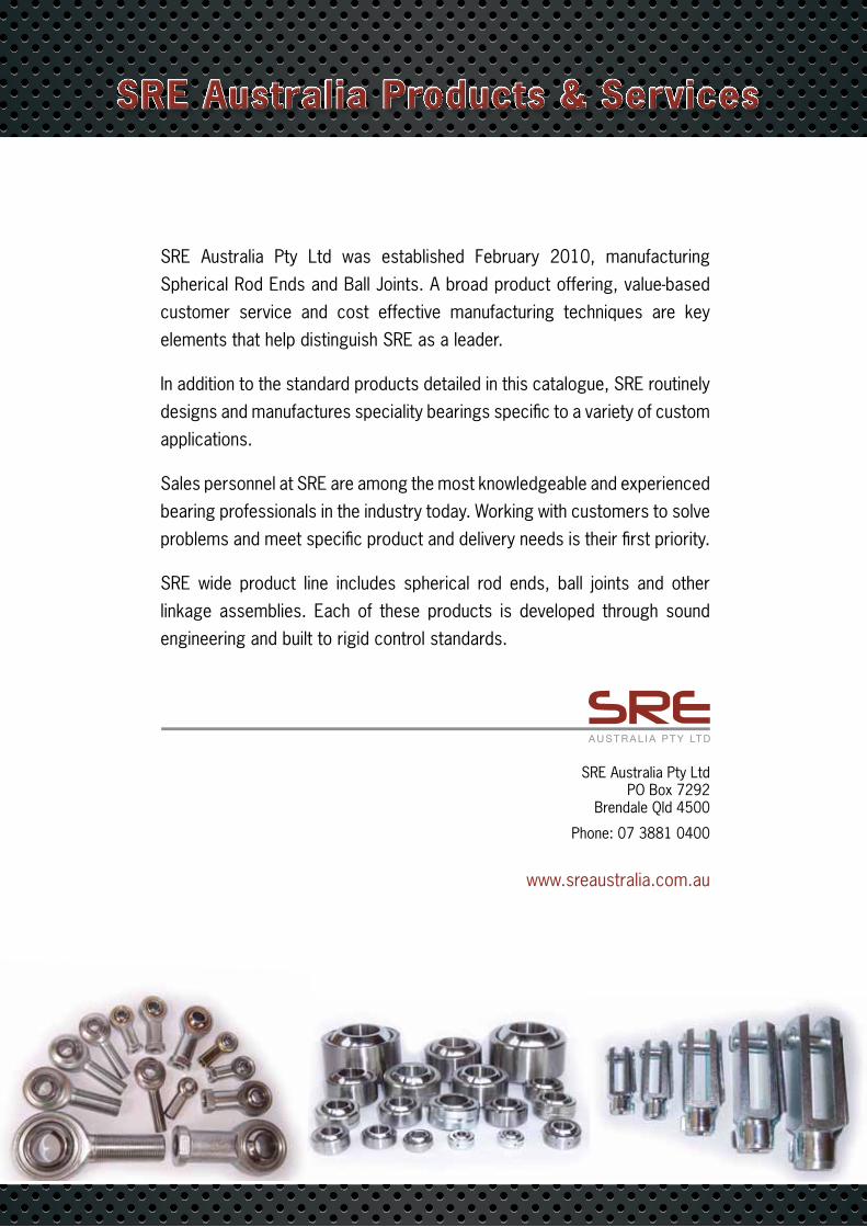
SRE Australia Pty Ltd was established February 2010, manufacturing Spherical Rod Ends and Ball Joints. A broad product offering, value-based customer service and cost effective manufacturing techniques are key elements that help distinguish SRE as a leader.
In addition to the standard products detailed in this catalogue, SRE routinely designs and manufactures speciality bearings specific to a variety of custom applications.
Sales personnel at SRE are among the most knowledgeable and experienced bearing professionals in the industry today. Working with customers to solve problems and meet specific product and delivery needs is their first priority.
SRE wide product line includes spherical rod ends, ball joints and other linkage assemblies. Each of these products is developed through sound engineering and built to rigid control standards.
SRE Australia Products & Services
SRE Australia Pty Ltd PO Box 7292
Brendale Qld 4500
Phone: 07 3881 0400
www.sreaustralia.com.au
3
Product Reference Guide
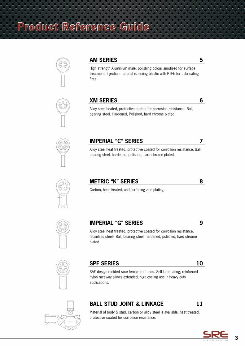
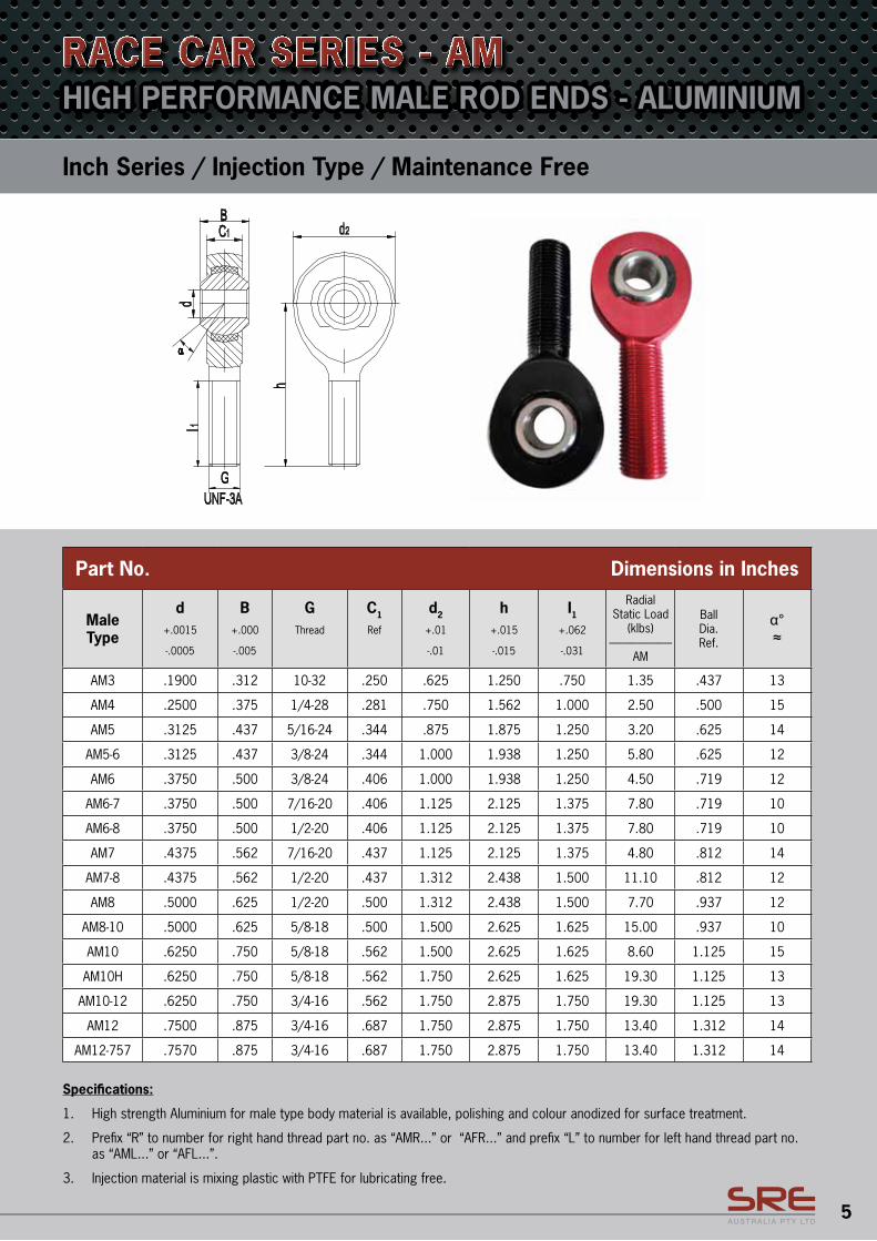
AM SERIES 5High strength Aluminium male, polishing colour anodized for surface treatment. Injection material is mixing plastic with PTFE for Lubricating Free.
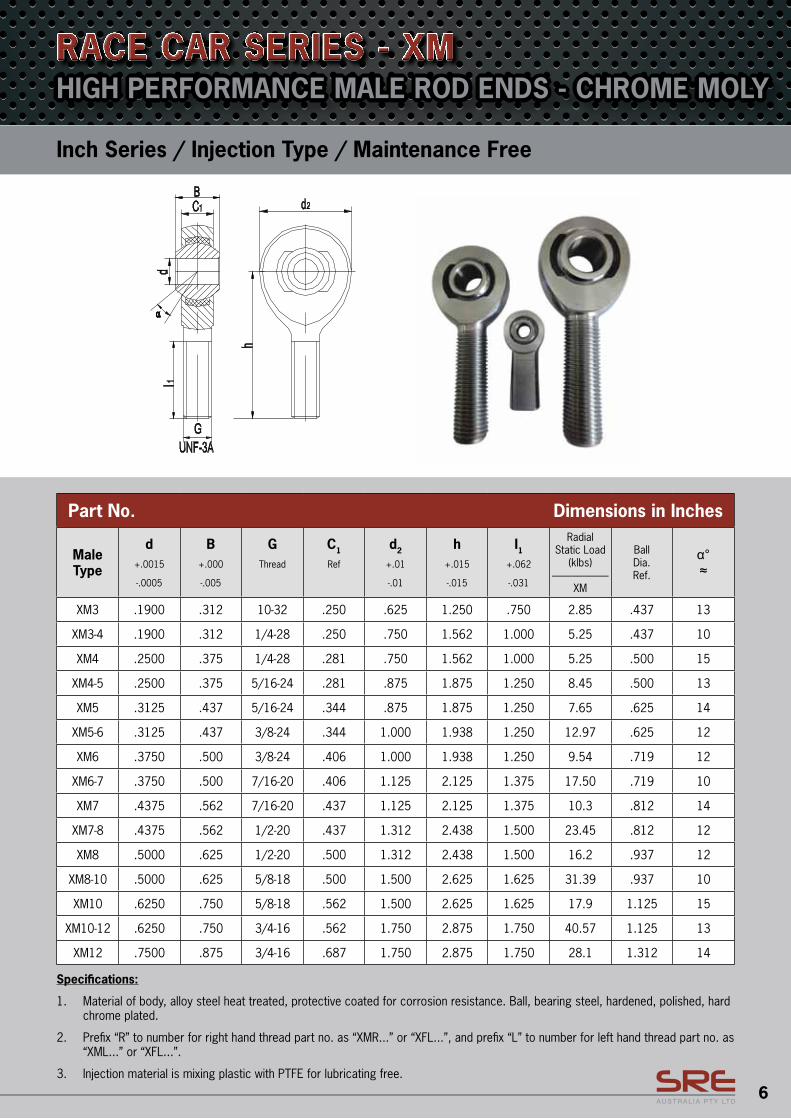
XM SERIES 6Alloy steel heated, protective coated for corrosion resistance. Ball, bearing steel. Hardened, Polished, hard chrome plated.
METRIC “K” SERIES 8Carbon, heat treated, and surfacing zinc plating.
IMPERIAL “G” SERIES 9Alloy steel heat treated, protective coated for corrosion resistance. (stainless steel). Ball, bearing steel, hardened, polished, hard chrome plated.
IMPERIAL “C” SERIES 7Alloy steel heat treated, protective coated for corrosion resistance. Ball, bearing steel, hardened, polished, hard chrome plated.
SPF SERIES 10SAE design molded race female rod ends. Self-Lubricating, reinforced nylon raceway allows extended, high cycling use in heavy duty applications.
BALL STUD JOINT & LINKAGE 11Material of body & stud, carbon or alloy steel is available, heat treated, protective coated for corrosion resistance.
4
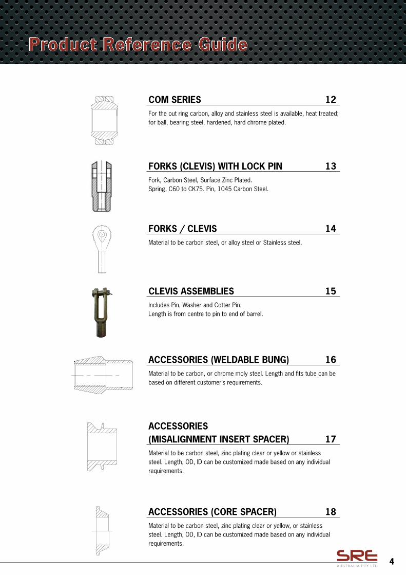
FORKS (CLEVIS) WITH LOCK PIN 13Fork, Carbon Steel, Surface Zinc Plated.Spring, C60 to CK75. Pin, 1045 Carbon Steel.
FORKS / CLEVIS 14Material to be carbon steel, or alloy steel or Stainless steel.
CLEVIS ASSEMBLIES 15Includes Pin, Washer and Cotter Pin.Length is from centre to pin to end of barrel.
ACCESSORIES (WELDABLE BUNG) 16Material to be carbon, or chrome moly steel. Length and fits tube can be based on different customer’s requirements.
ACCESSORIES (MISALIGNMENT INSERT SPACER) 17Material to be carbon steel, zinc plating clear or yellow or stainless steel. Length, OD, ID can be customized made based on any individual requirements.
ACCESSORIES (CORE SPACER) 18Material to be carbon steel, zinc plating clear or yellow, or stainless steel. Length, OD, ID can be customized made based on any individual requirements.
Product Reference Guide
COM SERIES 12For the out ring carbon, alloy and stainless steel is available, heat treated; for ball, bearing steel, hardened, hard chrome plated.
5
Part No. Dimensions in Inches
Male Type
d+.0015
-.0005
B+.000
-.005
GThread
C1
Ref
d2
+.01
-.01
h+.015
-.015
I1+.062
-.031
Radial Static Load
(klbs)--------------------------
AM
BallDia.Ref.
α°≈
AM3 .1900 .312 10-32 .250 .625 1.250 .750 1.35 .437 13
AM4 .2500 .375 1/4-28 .281 .750 1.562 1.000 2.50 .500 15
AM5 .3125 .437 5/16-24 .344 .875 1.875 1.250 3.20 .625 14
AM5-6 .3125 .437 3/8-24 .344 1.000 1.938 1.250 5.80 .625 12
AM6 .3750 .500 3/8-24 .406 1.000 1.938 1.250 4.50 .719 12
AM6-7 .3750 .500 7/16-20 .406 1.125 2.125 1.375 7.80 .719 10
AM6-8 .3750 .500 1/2-20 .406 1.125 2.125 1.375 7.80 .719 10
AM7 .4375 .562 7/16-20 .437 1.125 2.125 1.375 4.80 .812 14
AM7-8 .4375 .562 1/2-20 .437 1.312 2.438 1.500 11.10 .812 12
AM8 .5000 .625 1/2-20 .500 1.312 2.438 1.500 7.70 .937 12
AM8-10 .5000 .625 5/8-18 .500 1.500 2.625 1.625 15.00 .937 10
AM10 .6250 .750 5/8-18 .562 1.500 2.625 1.625 8.60 1.125 15
AM10H .6250 .750 5/8-18 .562 1.750 2.625 1.625 19.30 1.125 13
AM10-12 .6250 .750 3/4-16 .562 1.750 2.875 1.750 19.30 1.125 13
AM12 .7500 .875 3/4-16 .687 1.750 2.875 1.750 13.40 1.312 14
AM12-757 .7570 .875 3/4-16 .687 1.750 2.875 1.750 13.40 1.312 14
Specifications:
1. High strength Aluminium for male type body material is available, polishing and colour anodized for surface treatment.
2. Prefix “R” to number for right hand thread part no. as “AMR...” or “AFR...” and prefix “L” to number for left hand thread part no. as “AML...” or “AFL...”.
3. Injection material is mixing plastic with PTFE for lubricating free.
Inch Series / Injection Type / Maintenance Free
HIGH PERFORMANCE MALE ROD ENDS - ALUMINIUMRACE CAR SERIES - AM
6
Part No. Dimensions in Inches
Male Type
d+.0015
-.0005
B+.000
-.005
GThread
C1
Ref
d2
+.01
-.01
h+.015
-.015
I1+.062
-.031
Radial Static Load
(klbs)--------------------------
XM
BallDia.Ref.
α°≈
XM3 .1900 .312 10-32 .250 .625 1.250 .750 2.85 .437 13
XM3-4 .1900 .312 1/4-28 .250 .750 1.562 1.000 5.25 .437 10
XM4 .2500 .375 1/4-28 .281 .750 1.562 1.000 5.25 .500 15
XM4-5 .2500 .375 5/16-24 .281 .875 1.875 1.250 8.45 .500 13
XM5 .3125 .437 5/16-24 .344 .875 1.875 1.250 7.65 .625 14
XM5-6 .3125 .437 3/8-24 .344 1.000 1.938 1.250 12.97 .625 12
XM6 .3750 .500 3/8-24 .406 1.000 1.938 1.250 9.54 .719 12
XM6-7 .3750 .500 7/16-20 .406 1.125 2.125 1.375 17.50 .719 10
XM7 .4375 .562 7/16-20 .437 1.125 2.125 1.375 10.3 .812 14
XM7-8 .4375 .562 1/2-20 .437 1.312 2.438 1.500 23.45 .812 12
XM8 .5000 .625 1/2-20 .500 1.312 2.438 1.500 16.2 .937 12
XM8-10 .5000 .625 5/8-18 .500 1.500 2.625 1.625 31.39 .937 10
XM10 .6250 .750 5/8-18 .562 1.500 2.625 1.625 17.9 1.125 15
XM10-12 .6250 .750 3/4-16 .562 1.750 2.875 1.750 40.57 1.125 13
XM12 .7500 .875 3/4-16 .687 1.750 2.875 1.750 28.1 1.312 14
Specifications:
1. Material of body, alloy steel heat treated, protective coated for corrosion resistance. Ball, bearing steel, hardened, polished, hard chrome plated.
2. Prefix “R” to number for right hand thread part no. as “XMR...” or “XFL...”, and prefix “L” to number for left hand thread part no. as “XML...” or “XFL...”.
3. Injection material is mixing plastic with PTFE for lubricating free.
Inch Series / Injection Type / Maintenance Free
HIGH PERFORMANCE MALE ROD ENDS - CHROME MOLYRACE CAR SERIES - XM
7
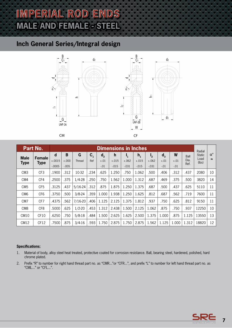
Specifications:
1. Material of body, alloy steel heat treated, protective coated for corrosion resistance. Ball, bearing steel, hardened, polished, hard chrome plated.
2. Prefix “R” to number for right hand thread part no. as “CMR...”or “CFR...”, and prefix “L” to number for left hand thread part no. as “CML...” or “CFL...”.
Inch General Series/Integral design
IMPERIAL ROD ENDS
Part No. Dimensions in InchesRadial Static Load (lbs)
α°≈Male
TypeFemale Type
d+.0015
-.0005
B+.000
-.005
GThread
C1
Ref
d2
+.01
-.01
h+.015
-.015
I1+.062
-.031
h1
+.015
-.015
I2+.062
-.031
d3
+.01
-.01
W+.01
-.01
BallDia.Ref.
CM3 CF3 .1900 .312 10-32 .234 .625 1.250 .750 1.062 .500 .406 .312 .437 2080 10
CM4 CF4 .2500 .375 1/4-28 .250 .750 1.562 1.000 1.312 .687 .469 .375 .500 3820 14
CM5 CF5 .3125 .437 5/16-24 .312 .875 1.875 1.250 1.375 .687 .500 .437 .625 5110 11
CM6 CF6 .3750 .500 3/8-24 .359 1.000 1.938 1.250 1.625 .812 .687 .562 .719 7600 11
CM7 CF7 .4375 .562 7/16-20 .406 1.125 2.125 1.375 1.812 .937 .750 .625 .812 9150 11
CM8 CF8 .5000 .625 1/2-20 .453 1.312 2.438 1.500 2.125 1.062 .875 .750 .937 12250 10
CM10 CF10 .6250 .750 5/8-18 .484 1.500 2.625 1.625 2.500 1.375 1.000 .875 1.125 13550 13
CM12 CF12 .7500 .875 3/4-16 .593 1.750 2.875 1.750 2.875 1.562 1.125 1.000 1.312 18820 12
MALE AND FEMALE - STEEL
8
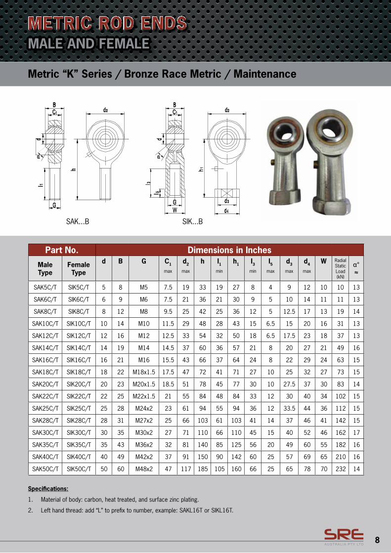
Metric “K” Series / Bronze Race Metric / Maintenance
MALE AND FEMALEMETRIC ROD ENDS
Part No. Dimensions in Inches
Male Type
Female Type
d B G C1
max
d2
max
h I1min
h1 I3min
I5max
d3
max
d4
max
W Radial Static Load (kN)
α°≈
SAK5C/T SIK5C/T 5 8 M5 7.5 19 33 19 27 8 4 9 12 10 10 13
SAK6C/T SIK6C/T 6 9 M6 7.5 21 36 21 30 9 5 10 14 11 11 13
SAK8C/T SIK8C/T 8 12 M8 9.5 25 42 25 36 12 5 12.5 17 13 19 14
SAK10C/T SIK10C/T 10 14 M10 11.5 29 48 28 43 15 6.5 15 20 16 31 13
SAK12C/T SIK12C/T 12 16 M12 12.5 33 54 32 50 18 6.5 17.5 23 18 37 13
SAK14C/T SIK14C/T 14 19 M14 14.5 37 60 36 57 21 8 20 27 21 49 16
SAK16C/T SIK16C/T 16 21 M16 15.5 43 66 37 64 24 8 22 29 24 63 15
SAK18C/T SIK18C/T 18 22 M18x1.5 17.5 47 72 41 71 27 10 25 32 27 73 15
SAK20C/T SIK20C/T 20 23 M20x1.5 18.5 51 78 45 77 30 10 27.5 37 30 83 14
SAK22C/T SIK22C/T 22 25 M22x1.5 21 55 84 48 84 33 12 30 40 34 102 15
SAK25C/T SIK25C/T 25 28 M24x2 23 61 94 55 94 36 12 33.5 44 36 112 15
SAK28C/T SIK28C/T 28 31 M27x2 25 66 103 61 103 41 14 37 46 41 142 15
SAK30C/T SIK30C/T 30 35 M30x2 27 71 110 66 110 45 15 40 52 46 162 17
SAK35C/T SIK35C/T 35 43 M36x2 32 81 140 85 125 56 20 49 60 55 182 16
SAK40C/T SIK40C/T 40 49 M42x2 37 91 150 90 142 60 25 57 69 65 210 16
SAK50C/T SIK50C/T 50 60 M48x2 47 117 185 105 160 66 25 65 78 70 232 14
Specifications:
1. Material of body: carbon, heat treated, and surface zinc plating.
2. Left hand thread: add “L” to prefix to number, example: SAKL16T or SIKL16T.
9
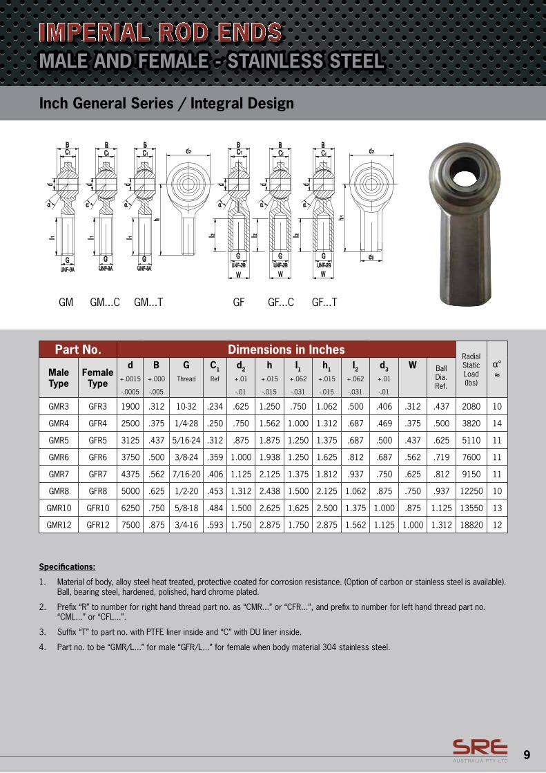
MALE AND FEMALE - STAINLESS STEEL
Part No. Dimensions in InchesRadial Static Load (lbs)
α°≈Male
TypeFemale Type
d+.0015
-.0005
B+.000
-.005
GThread
C1
Ref
d2
+.01
-.01
h+.015
-.015
I1+.062
-.031
h1
+.015
-.015
I2+.062
-.031
d3
+.01
-.01
W BallDia.Ref.
GMR3 GFR3 1900 .312 10-32 .234 .625 1.250 .750 1.062 .500 .406 .312 .437 2080 10
GMR4 GFR4 2500 .375 1/4-28 .250 .750 1.562 1.000 1.312 .687 .469 .375 .500 3820 14
GMR5 GFR5 3125 .437 5/16-24 .312 .875 1.875 1.250 1.375 .687 .500 .437 .625 5110 11
GMR6 GFR6 3750 .500 3/8-24 .359 1.000 1.938 1.250 1.625 .812 .687 .562 .719 7600 11
GMR7 GFR7 4375 .562 7/16-20 .406 1.125 2.125 1.375 1.812 .937 .750 .625 .812 9150 11
GMR8 GFR8 5000 .625 1/2-20 .453 1.312 2.438 1.500 2.125 1.062 .875 .750 .937 12250 10
GMR10 GFR10 6250 .750 5/8-18 .484 1.500 2.625 1.625 2.500 1.375 1.000 .875 1.125 13550 13
GMR12 GFR12 7500 .875 3/4-16 .593 1.750 2.875 1.750 2.875 1.562 1.125 1.000 1.312 18820 12
Inch General Series / Integral Design
IMPERIAL ROD ENDS
Specifications:
1. Material of body, alloy steel heat treated, protective coated for corrosion resistance. (Option of carbon or stainless steel is available). Ball, bearing steel, hardened, polished, hard chrome plated.
2. Prefix “R” to number for right hand thread part no. as “CMR...” or “CFR...”, and prefix to number for left hand thread part no. “CML...” or “CFL...”.
3. Suffix “T” to part no. with PTFE liner inside and “C” with DU liner inside.
4. Part no. to be “GMR/L...” for male “GFR/L...” for female when body material 304 stainless steel.
10
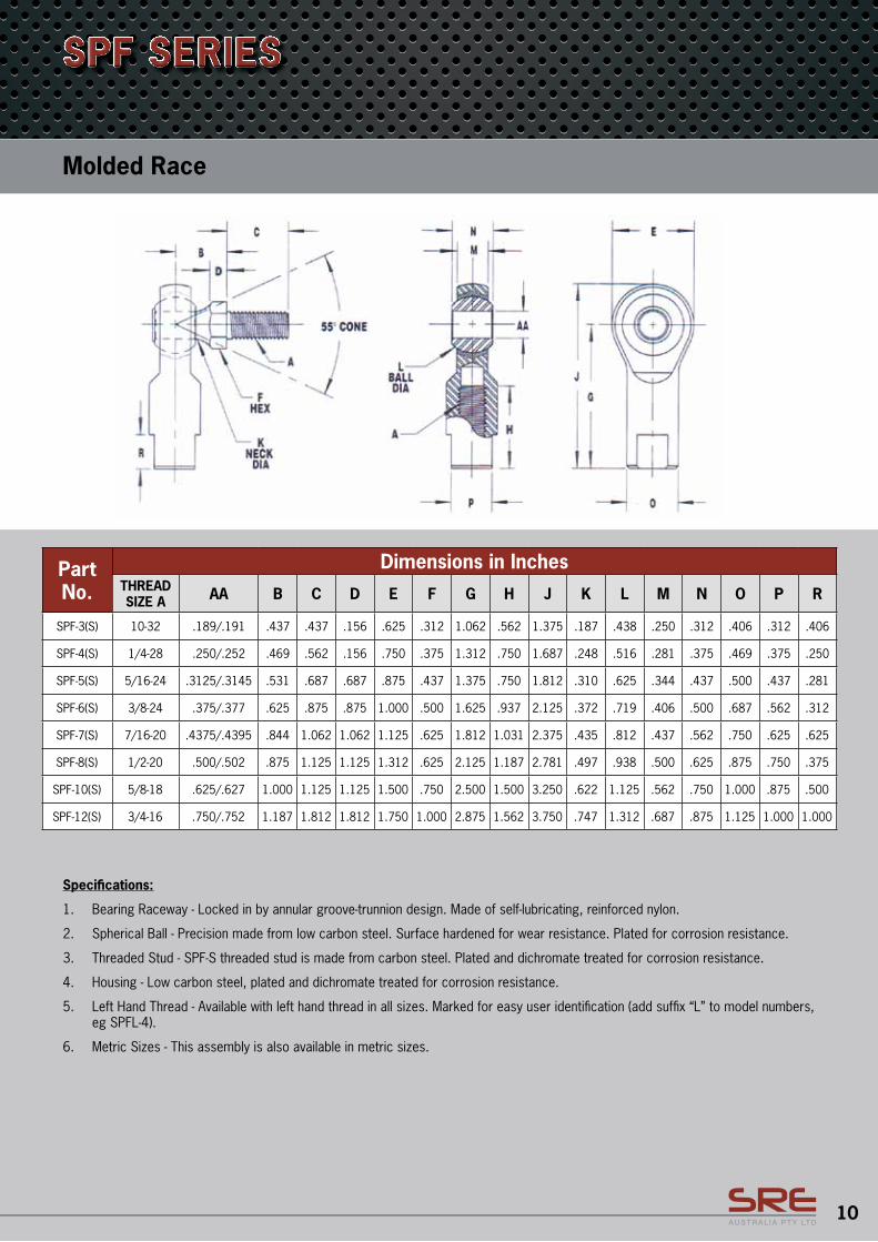
Specifications:
1. Bearing Raceway - Locked in by annular groove-trunnion design. Made of self-lubricating, reinforced nylon.
2. Spherical Ball - Precision made from low carbon steel. Surface hardened for wear resistance. Plated for corrosion resistance.
3. Threaded Stud - SPF-S threaded stud is made from carbon steel. Plated and dichromate treated for corrosion resistance.
4. Housing - Low carbon steel, plated and dichromate treated for corrosion resistance.
5. Left Hand Thread - Available with left hand thread in all sizes. Marked for easy user identification (add suffix “L” to model numbers, eg SPFL-4).
6. Metric Sizes - This assembly is also available in metric sizes.
Molded Race
SPF SERIES
Part No.
Dimensions in InchesTHREAD SIZE A AA B C D E F G H J K L M N O P R
SPF-3(S) 10-32 .189/.191 .437 .437 .156 .625 .312 1.062 .562 1.375 .187 .438 .250 .312 .406 .312 .406
SPF-4(S) 1/4-28 .250/.252 .469 .562 .156 .750 .375 1.312 .750 1.687 .248 .516 .281 .375 .469 .375 .250
SPF-5(S) 5/16-24 .3125/.3145 .531 .687 .687 .875 .437 1.375 .750 1.812 .310 .625 .344 .437 .500 .437 .281
SPF-6(S) 3/8-24 .375/.377 .625 .875 .875 1.000 .500 1.625 .937 2.125 .372 .719 .406 .500 .687 .562 .312
SPF-7(S) 7/16-20 .4375/.4395 .844 1.062 1.062 1.125 .625 1.812 1.031 2.375 .435 .812 .437 .562 .750 .625 .625
SPF-8(S) 1/2-20 .500/.502 .875 1.125 1.125 1.312 .625 2.125 1.187 2.781 .497 .938 .500 .625 .875 .750 .375
SPF-10(S) 5/8-18 .625/.627 1.000 1.125 1.125 1.500 .750 2.500 1.500 3.250 .622 1.125 .562 .750 1.000 .875 .500
SPF-12(S) 3/4-16 .750/.752 1.187 1.812 1.812 1.750 1.000 2.875 1.562 3.750 .747 1.312 .687 .875 1.125 1.000 1.000
11
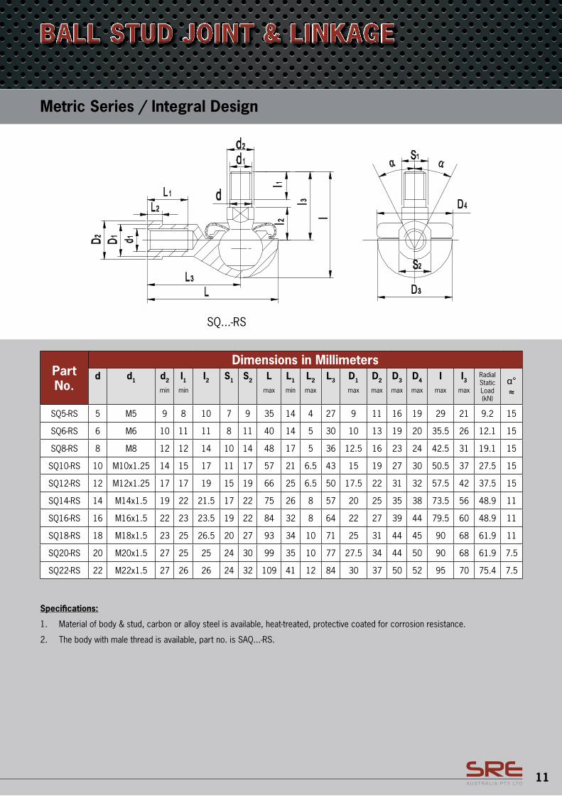
Specifications:
1. Material of body & stud, carbon or alloy steel is available, heat-treated, protective coated for corrosion resistance.
2. The body with male thread is available, part no. is SAQ...-RS.
Metric Series / Integral Design
BALL STUD JOINT & LINKAGE
Part No.
Dimensions in Millimetersd d1 d2
min
I1min
I2 S1 S2 Lmax
L1
min
L2
max
L3 D1
max
D2
max
D3
max
D4
max
Imax
I3max
Radial Static Load (kN)
α°≈
SQ5-RS 5 M5 9 8 10 7 9 35 14 4 27 9 11 16 19 29 21 9.2 15
SQ6-RS 6 M6 10 11 11 8 11 40 14 5 30 10 13 19 20 35.5 26 12.1 15
SQ8-RS 8 M8 12 12 14 10 14 48 17 5 36 12.5 16 23 24 42.5 31 19.1 15
SQ10-RS 10 M10x1.25 14 15 17 11 17 57 21 6.5 43 15 19 27 30 50.5 37 27.5 15
SQ12-RS 12 M12x1.25 17 17 19 15 19 66 25 6.5 50 17.5 22 31 32 57.5 42 37.5 15
SQ14-RS 14 M14x1.5 19 22 21.5 17 22 75 26 8 57 20 25 35 38 73.5 56 48.9 11
SQ16-RS 16 M16x1.5 22 23 23.5 19 22 84 32 8 64 22 27 39 44 79.5 60 48.9 11
SQ18-RS 18 M18x1.5 23 25 26.5 20 27 93 34 10 71 25 31 44 45 90 68 61.9 11
SQ20-RS 20 M20x1.5 27 25 25 24 30 99 35 10 77 27.5 34 44 50 90 68 61.9 7.5
SQ22-RS 22 M22x1.5 27 26 26 24 32 109 41 12 84 30 37 50 52 95 70 75.4 7.5
12
Part No.
Dimensions in InchesRadial Static Load (klbs)
α°≈
d+.0015
-.0005
D+.0000
-.0005
B+.000
-.005
C+.005
-.005
dk≈
rmin
chamfer
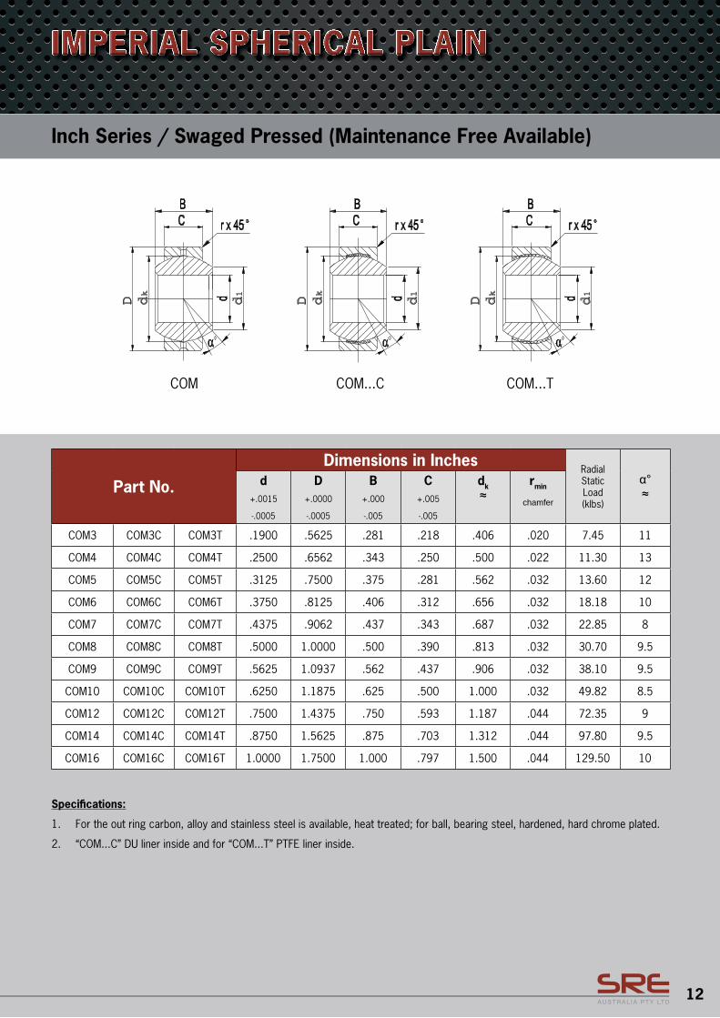
COM3 COM3C COM3T .1900 .5625 .281 .218 .406 .020 7.45 11
COM4 COM4C COM4T .2500 .6562 .343 .250 .500 .022 11.30 13
COM5 COM5C COM5T .3125 .7500 .375 .281 .562 .032 13.60 12
COM6 COM6C COM6T .3750 .8125 .406 .312 .656 .032 18.18 10
COM7 COM7C COM7T .4375 .9062 .437 .343 .687 .032 22.85 8
COM8 COM8C COM8T .5000 1.0000 .500 .390 .813 .032 30.70 9.5
COM9 COM9C COM9T .5625 1.0937 .562 .437 .906 .032 38.10 9.5
COM10 COM10C COM10T .6250 1.1875 .625 .500 1.000 .032 49.82 8.5
COM12 COM12C COM12T .7500 1.4375 .750 .593 1.187 .044 72.35 9
COM14 COM14C COM14T .8750 1.5625 .875 .703 1.312 .044 97.80 9.5
COM16 COM16C COM16T 1.0000 1.7500 1.000 .797 1.500 .044 129.50 10
Specifications:
1. For the out ring carbon, alloy and stainless steel is available, heat treated; for ball, bearing steel, hardened, hard chrome plated.
2. “COM...C” DU liner inside and for “COM...T” PTFE liner inside.
Inch Series / Swaged Pressed (Maintenance Free Available)
IMPERIAL SPHERICAL PLAIN
COM COM...C COM...T
d1
D dk
D dk
D dk
d1
d1
13
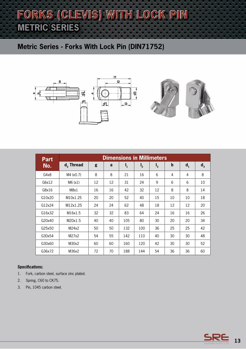
METRIC SERIES
Part No.
Dimensions in Millimetersd2 Thread g a I1 I2 I3 b d1 d3
G4x8 M4 (x0.7) 8 8 21 16 6 4 4 8
G6x12 M6 (x1) 12 12 31 24 9 6 6 10
G8x16 M8x1 16 16 42 32 12 8 8 14
G10x20 M10x1.25 20 20 52 40 15 10 10 18
G12x24 M12x1.25 24 24 62 48 18 12 12 20
G16x32 M16x1.5 32 32 83 64 24 16 16 26
G20x40 M20x1.5 40 40 105 80 30 20 20 34
G25x50 M24x2 50 50 132 100 36 25 25 42
G30x54 M27x2 54 55 142 110 40 30 30 48
G30x60 M30x2 60 60 160 120 42 30 30 52
G36x72 M36x2 72 70 188 144 54 36 36 60
Specifications:
1. Fork, carbon steel, surface zinc plated.
2. Spring, C60 to CK75.
3. Pin, 1045 carbon steel.
Metric Series - Forks With Lock Pin (DIN71752)
FORKS (CLEVIS) WITH LOCK PIN
36
Forks (Clevis) with Lock Pin
Metric Series- Forks With Lock Pin (DIN71752)
Dimension Chart:
Dimensions in Millimeters Part No.
d2-Thread g a l1 l2 l3 b d1 d3 G4x8 M4 (x0.7) 8 8 21 16 6 4 4 8 G6x12 M6 (x1) 12 12 31 24 9 6 6 10 G8x16 M8x1 16 16 42 32 12 8 8 14 G10x20 M10x1.25 20 20 52 40 15 10 10 18 G12x24 M12x1.25 24 24 62 48 18 12 12 20 G16x32 M16 x 1.5 32 32 83 64 24 16 16 26 G20x40 M20 x 1.5 40 40 105 80 30 20 20 34 G25x50 M24 x 2 50 50 132 100 36 25 25 42 G30x54 M27 x 2 54 55 142 110 40 30 30 48 G30x60 M30 x 2 60 60 160 120 42 30 30 52 G36x72 M36 x 2 72 70 188 144 54 36 36 60
Notes: Fork, carbon steel, surface zinc plated. Spring, C60 to CK75. Pin, 1045 carbon steel.
14
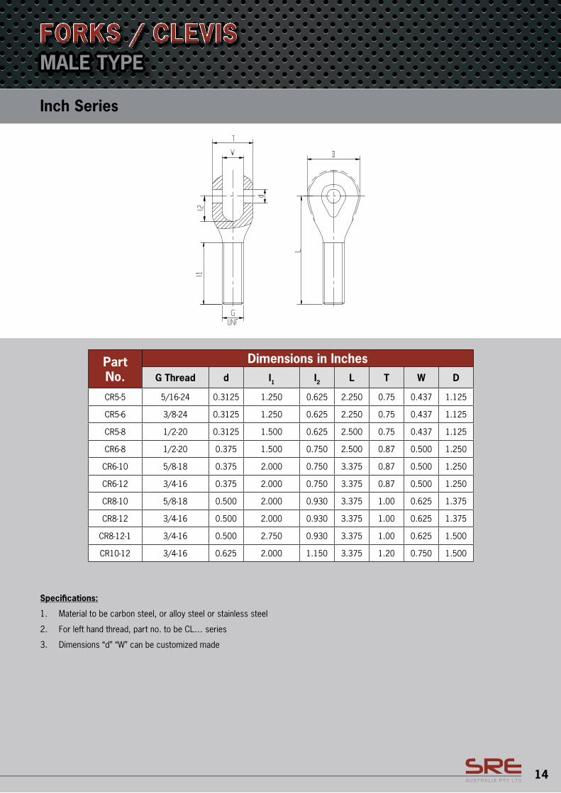
Specifications:
1. Material to be carbon steel, or alloy steel or stainless steel
2. For left hand thread, part no. to be CL… series
3. Dimensions “d” “W” can be customized made
Inch Series
MALE TYPEFORKS / CLEVIS
Part No.
Dimensions in InchesG Thread d I1 I2 L T W D
CR5-5 5/16-24 0.3125 1.250 0.625 2.250 0.75 0.437 1.125
CR5-6 3/8-24 0.3125 1.250 0.625 2.250 0.75 0.437 1.125
CR5-8 1/2-20 0.3125 1.500 0.625 2.500 0.75 0.437 1.125
CR6-8 1/2-20 0.375 1.500 0.750 2.500 0.87 0.500 1.250
CR6-10 5/8-18 0.375 2.000 0.750 3.375 0.87 0.500 1.250
CR6-12 3/4-16 0.375 2.000 0.750 3.375 0.87 0.500 1.250
CR8-10 5/8-18 0.500 2.000 0.930 3.375 1.00 0.625 1.375
CR8-12 3/4-16 0.500 2.000 0.930 3.375 1.00 0.625 1.375
CR8-12-1 3/4-16 0.500 2.750 0.930 3.375 1.00 0.625 1.500
CR10-12 3/4-16 0.625 2.000 1.150 3.375 1.20 0.750 1.500
15
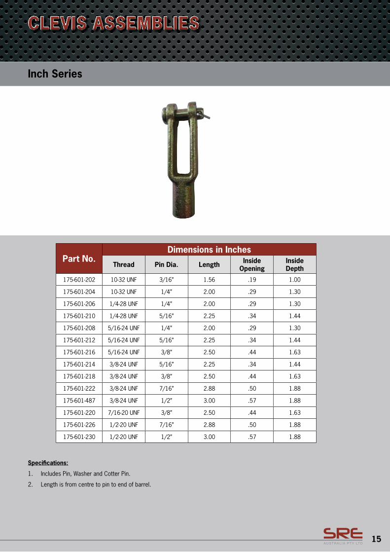
Specifications:
1. Includes Pin, Washer and Cotter Pin.
2. Length is from centre to pin to end of barrel.
Inch Series
CLEVIS ASSEMBLIES
Part No.Dimensions in Inches
Thread Pin Dia. Length Inside Opening
Inside Depth
175-601-202 10-32 UNF 3/16” 1.56 .19 1.00
175-601-204 10-32 UNF 1/4” 2.00 .29 1.30
175-601-206 1/4-28 UNF 1/4” 2.00 .29 1.30
175-601-210 1/4-28 UNF 5/16” 2.25 .34 1.44
175-601-208 5/16-24 UNF 1/4” 2.00 .29 1.30
175-601-212 5/16-24 UNF 5/16” 2.25 .34 1.44
175-601-216 5/16-24 UNF 3/8” 2.50 .44 1.63
175-601-214 3/8-24 UNF 5/16” 2.25 .34 1.44
175-601-218 3/8-24 UNF 3/8” 2.50 .44 1.63
175-601-222 3/8-24 UNF 7/16” 2.88 .50 1.88
175-601-487 3/8-24 UNF 1/2” 3.00 .57 1.88
175-601-220 7/16-20 UNF 3/8” 2.50 .44 1.63
175-601-226 1/2-20 UNF 7/16” 2.88 .50 1.88
175-601-230 1/2-20 UNF 1/2” 3.00 .57 1.88
16
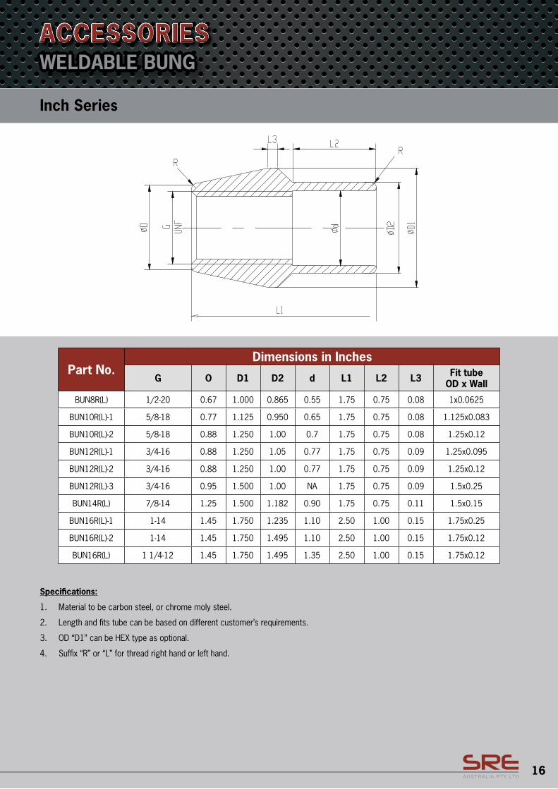
WELDABLE BUNG
Part No.Dimensions in Inches
G O D1 D2 d L1 L2 L3 Fit tube OD x Wall
BUN8R(L) 1/2-20 0.67 1.000 0.865 0.55 1.75 0.75 0.08 1x0.0625
BUN10R(L)-1 5/8-18 0.77 1.125 0.950 0.65 1.75 0.75 0.08 1.125x0.083
BUN10R(L)-2 5/8-18 0.88 1.250 1.00 0.7 1.75 0.75 0.08 1.25x0.12
BUN12R(L)-1 3/4-16 0.88 1.250 1.05 0.77 1.75 0.75 0.09 1.25x0.095
BUN12R(L)-2 3/4-16 0.88 1.250 1.00 0.77 1.75 0.75 0.09 1.25x0.12
BUN12R(L)-3 3/4-16 0.95 1.500 1.00 NA 1.75 0.75 0.09 1.5x0.25
BUN14R(L) 7/8-14 1.25 1.500 1.182 0.90 1.75 0.75 0.11 1.5x0.15
BUN16R(L)-1 1-14 1.45 1.750 1.235 1.10 2.50 1.00 0.15 1.75x0.25
BUN16R(L)-2 1-14 1.45 1.750 1.495 1.10 2.50 1.00 0.15 1.75x0.12
BUN16R(L) 1 1/4-12 1.45 1.750 1.495 1.35 2.50 1.00 0.15 1.75x0.12
Inch Series
ACCESSORIES
Specifications:
1. Material to be carbon steel, or chrome moly steel.
2. Length and fits tube can be based on different customer’s requirements.
3. OD “D1” can be HEX type as optional.
4. Suffix “R” or “L” for thread right hand or left hand.
17
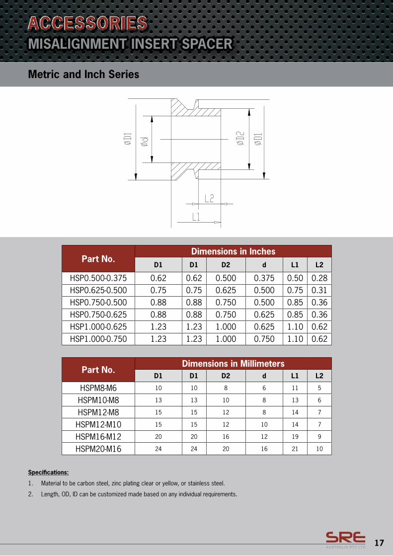
Metric and Inch Series
MISALIGNMENT INSERT SPACERACCESSORIES
Part No.Dimensions in Inches
D1 D1 D2 d L1 L2
HSP0.500-0.375 0.62 0.62 0.500 0.375 0.50 0.28HSP0.625-0.500 0.75 0.75 0.625 0.500 0.75 0.31HSP0.750-0.500 0.88 0.88 0.750 0.500 0.85 0.36HSP0.750-0.625 0.88 0.88 0.750 0.625 0.85 0.36HSP1.000-0.625 1.23 1.23 1.000 0.625 1.10 0.62HSP1.000-0.750 1.23 1.23 1.000 0.750 1.10 0.62
Part No.Dimensions in Millimeters
D1 D1 D2 d L1 L2
HSPM8-M6 10 10 8 6 11 5
HSPM10-M8 13 13 10 8 13 6
HSPM12-M8 15 15 12 8 14 7
HSPM12-M10 15 15 12 10 14 7
HSPM16-M12 20 20 16 12 19 9
HSPM20-M16 24 24 20 16 21 10
Specifications:
1. Material to be carbon steel, zinc plating clear or yellow, or stainless steel.
2. Length, OD, ID can be customized made based on any individual requirements.
18
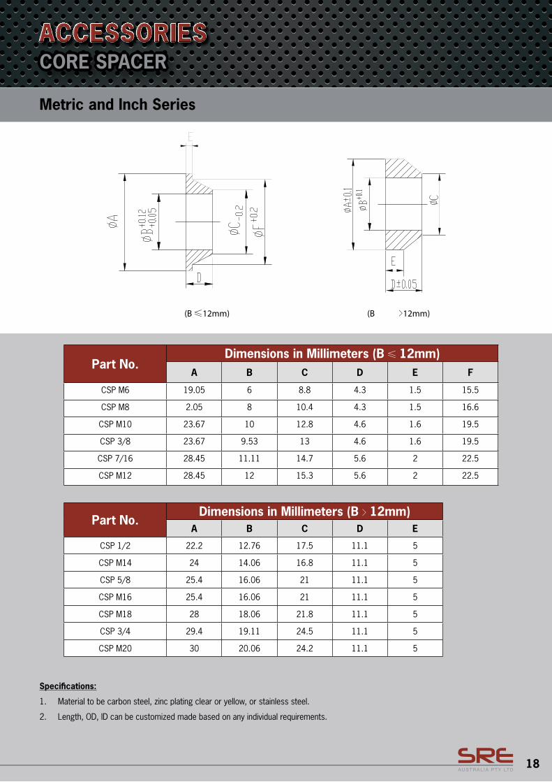
CORE SPACER
Part No.Dimensions in Millimeters (B 12mm)
A B C D E F
CSP M6 19.05 6 8.8 4.3 1.5 15.5
CSP M8 2.05 8 10.4 4.3 1.5 16.6
CSP M10 23.67 10 12.8 4.6 1.6 19.5
CSP 3/8 23.67 9.53 13 4.6 1.6 19.5
CSP 7/16 28.45 11.11 14.7 5.6 2 22.5
CSP M12 28.45 12 15.3 5.6 2 22.5
Part No.Dimensions in Millimeters (B 12mm)
A B C D E
CSP 1/2 22.2 12.76 17.5 11.1 5
CSP M14 24 14.06 16.8 11.1 5
CSP 5/8 25.4 16.06 21 11.1 5
CSP M16 25.4 16.06 21 11.1 5
CSP M18 28 18.06 21.8 11.1 5
CSP 3/4 29.4 19.11 24.5 11.1 5
CSP M20 30 20.06 24.2 11.1 5
Specifications:
1. Material to be carbon steel, zinc plating clear or yellow, or stainless steel.
2. Length, OD, ID can be customized made based on any individual requirements.
Metric and Inch Series
ACCESSORIES
SRE Australia Pty Ltd PO Box 7292
Brendale Qld 4500
Phone: 07 3881 0400
www.sreaustralia.com.au