Embed Size (px)
Citation preview
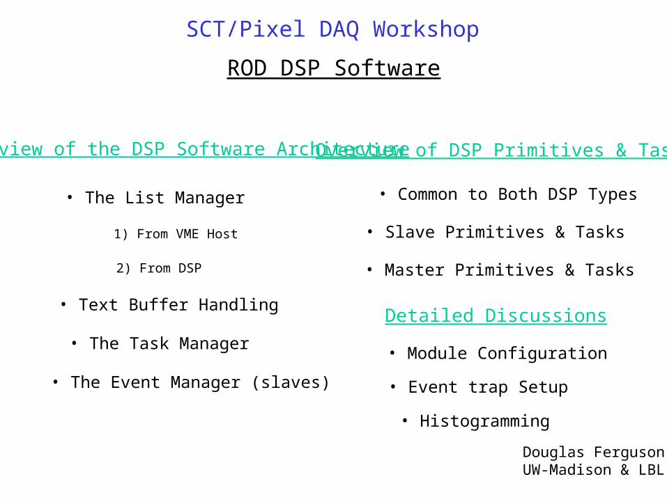
ROD DSP Software
Overview of the DSP Software Architecture
• The List Manager
• The Task Manager
• The Event Manager (slaves)
• Text Buffer Handling
1) From VME Host
2) From DSP
Overview of DSP Primitives & Tasks
• Common to Both DSP Types
• Slave Primitives & Tasks
• Master Primitives & Tasks
Douglas FergusonUW-Madison & LBL
SCT/Pixel DAQ Workshop
Detailed Discussions
• Module Configuration
• Event trap Setup
• Histogramming
Lengthindex
# primitiveslist version
Lengthindex
prim. IDprim version
Data
Lengthindex
prim. IDprim version
Data
Lengthchecksum
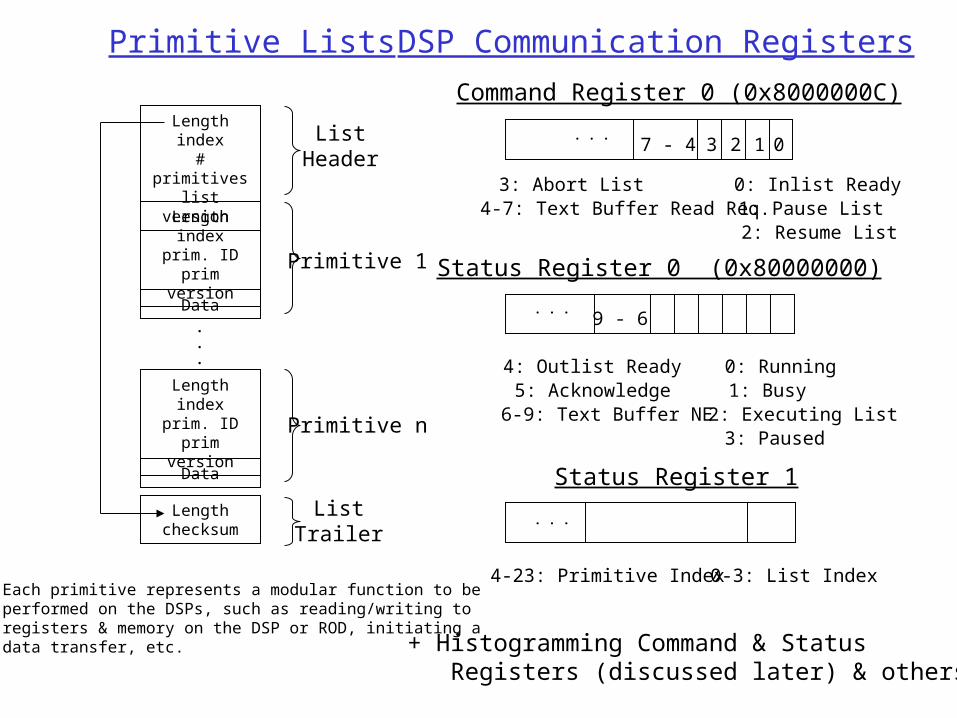
ListHeader
Primitive Lists
.
.
.
Primitive 1
Primitive n
ListTrailer
DSP Communication Registers
0: Running1: Busy2: Executing List3: Paused
4: Outlist Ready5: Acknowledge6-9: Text Buffer NE
...
0: Inlist Ready1: Pause List2: Resume List
3: Abort List4-7: Text Buffer Read Req.
Command Register 0 (0x8000000C)
...
1 0237 - 4
Status Register 0 (0x80000000)
9 - 6
0-3: List Index4-23: Primitive Index
...
Status Register 1
+ Histogramming Command & Status Registers (discussed later) & others.
Each primitive represents a modular function to beperformed on the DSPs, such as reading/writing toregisters & memory on the DSP or ROD, initiating adata transfer, etc.
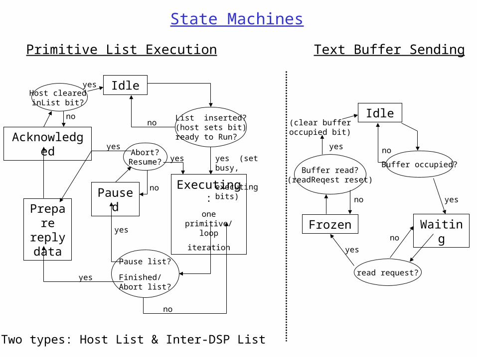
State Machines
Idle
List inserted?(host sets bit)ready to Run?
no
Executing:
one primitive/ loop
iteration
yes (set busy, executing bits)
Pause list?
Finished/Abort list?
Abort?Resume?
Paused
yes
no
Prepare reply data
Acknowledged
Host clearedinList bit?
yes
no
yes
yes
yes
no
Primitive List Execution Text Buffer Sending
Idle
Buffer occupied?
WaitingFrozen
yes
no
read request?
yes
no
Buffer read?(readReqest reset)
no
(clear bufferoccupied bit)
yes
Two types: Host List & Inter-DSP List
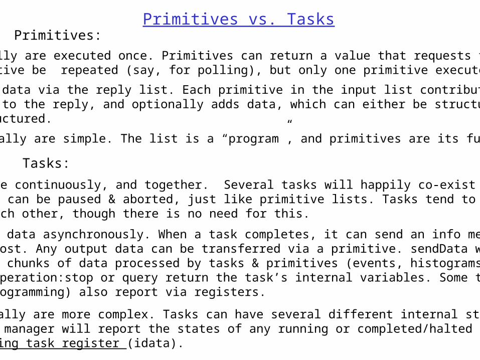
Primitives vs. TasksPrimitives:
o Generally are executed once. Primitives can return a value that requests that the primitive be repeated (say, for polling), but only one primitive executes at a time.
o Return data via the reply list. Each primitive in the input list contributes a header block to the reply, and optionally adds data, which can either be structured or unstructured.
o Generally are simple. The list is a “program”, and primitives are its functions.
Tasks:
o Execute continuously, and together. Several tasks will happily co-exist on a DSP. Tasks can be paused & aborted, just like primitive lists. Tasks tend to be independent of each other, though there is no need for this.
o Return data asynchronously. When a task completes, it can send an info message to the host. Any output data can be transferred via a primitive. sendData will handle large chunks of data processed by tasks & primitives (events, histograms, fits etc.); taskOperation:stop or query return the task’s internal variables. Some tasks (histogramming) also report via registers.
o Typically are more complex. Tasks can have several different internal states; the task manager will report the states of any running or completed/halted tasks in the running task register (idata).
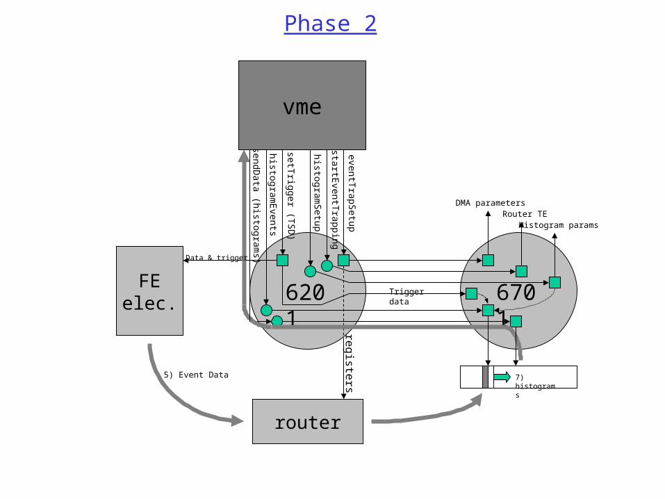
6701
7) histograms
6201
router
FEelec.
1) eventTr apSet up
r egist er s
Router TE
4) s etTr igger ( T
SD)
5) Event Data
8) s endData ( his t ogr am
s )
2) s tar tEvent T
rapping
6) his t ogramE
vent s
DMA parameters
3) his t ogramSet up
Data & trigger
vme
Histogram params
Trigger data
Phase 2
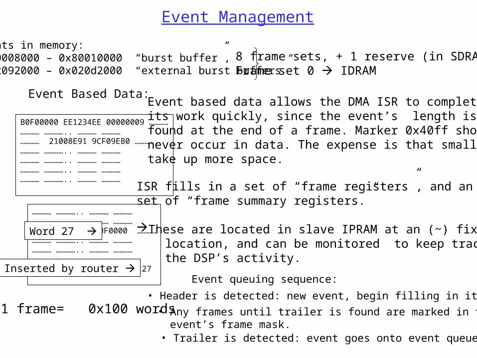
B0F00000 EE1234EE 00000009 …………………… ………….. ………… …………………… 21008E91 9CF09EB0 ………..………… ………….. ………… …………………… ………….. ………… …………………… ………….. ………… …………………… ………….. ………… …………
Event Management
Events in memory: 0x80008000 – 0x80010000 “burst buffer”,0x02092000 – 0x020d2000 “external burst buffers”
………… ………….. ………… …………………… ………….. ………… …………………… ………….. E0F0000 …………………… ………….. ………… …………………… ………….. ………… …………………… ………….. ………… …………………… ………….. ………… 40FF0127
1 frame= 0x100 words
Word 27
Inserted by router
Event Based Data:Event based data allows the DMA ISR to completeits work quickly, since the event’s length is alwaysfound at the end of a frame. Marker 0x40ff shouldnever occur in data. The expense is that small eventstake up more space.
ISR fills in a set of “frame registers”, and an auxiliaryset of “frame summary registers.”
These are located in slave IPRAM at an (~) fixed location, and can be monitored to keep track of the DSP’s activity.
8 frame sets, + 1 reserve (in SDRAM).Frame set 0 IDRAM
• Any frames until trailer is found are marked in the event’s frame mask.
• Header is detected: new event, begin filling in its data.
• Trailer is detected: event goes onto event queue.
Event queuing sequence:
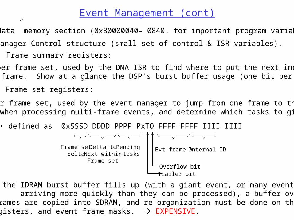
Event Management (cont)
• defined as 0xSSSD DDDD PPPP PxTO FFFF FFFF IIII IIII
In the “idata” memory section (0x80000040- 0840, for important program variables):
• 32 per frame set, used by the event manager to jump from one frame to the next when processing multi-frame events, and determine which tasks to give them to.
Frame set registers:
Internal IDEvt frame #Pending tasks
Delta toNext withinFrame set
Frame setdelta
Overflow bitTrailer bit
Frame summary registers:
• One per frame set, used by the DMA ISR to find where to put the next incoming data frame. Show at a glance the DSP’s burst buffer usage (one bit per frame).
Overflows: if the IDRAM burst buffer fills up (with a giant event, or many events arriving more quickly than they can be processed), a buffer overflow occurs. All IPRAM frames are copied into SDRAM, and re-organization must be done on the frame set registers, and event frame masks. EXPENSIVE.
Event Manager Control structure (small set of control & ISR variables).
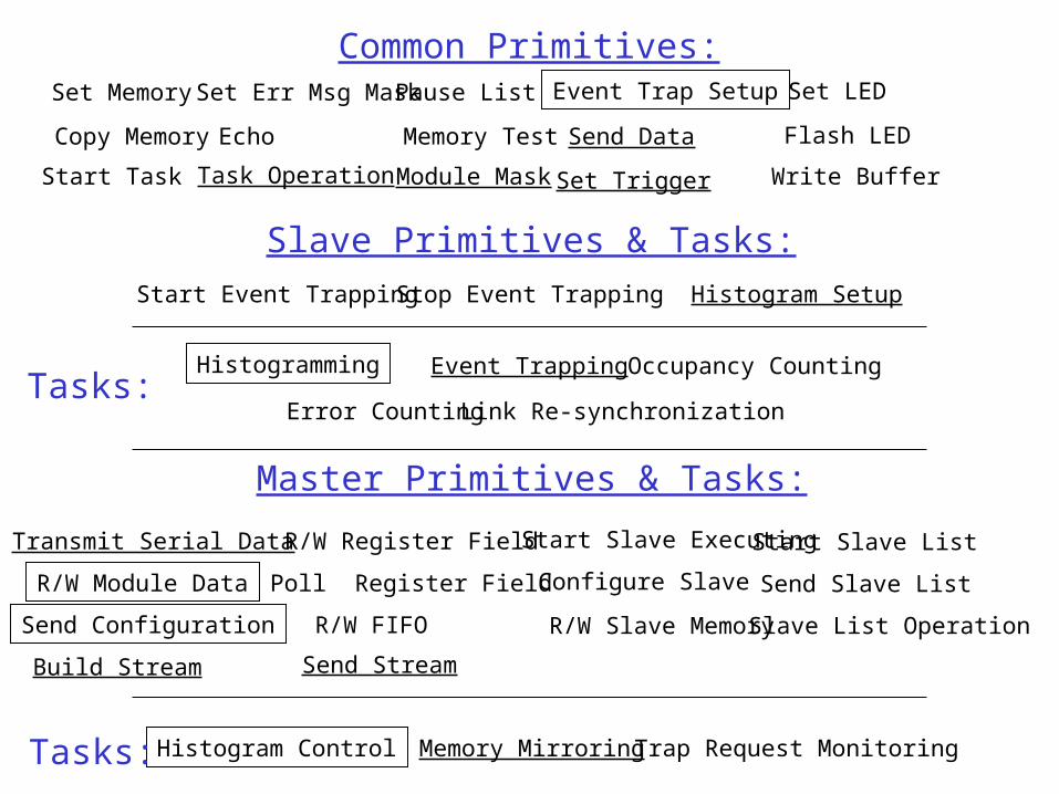
Common Primitives:
Echo
Set Err Msg Mask Pause List Event Trap SetupSet Memory
Copy Memory Memory Test Send Data
Module Mask Set TriggerStart Task Task Operation Write Buffer
Slave Primitives & Tasks:
Start Event Trapping Stop Event Trapping Histogram Setup
Histogramming Event Trapping Occupancy Counting
Error Counting Link Re-synchronization
Set LED
Flash LED
Transmit Serial Data Start Slave ExecutingR/W Register Field
R/W Slave Memory
Send Slave List
Build Stream
Slave List Operation
Send Stream
Configure SlavePoll Register FieldR/W Module Data
R/W FIFO
Start Slave List
Send Configuration
Master Primitives & Tasks:
Histogram Control Memory Mirroring Trap Request Monitoring
Tasks:
Tasks:
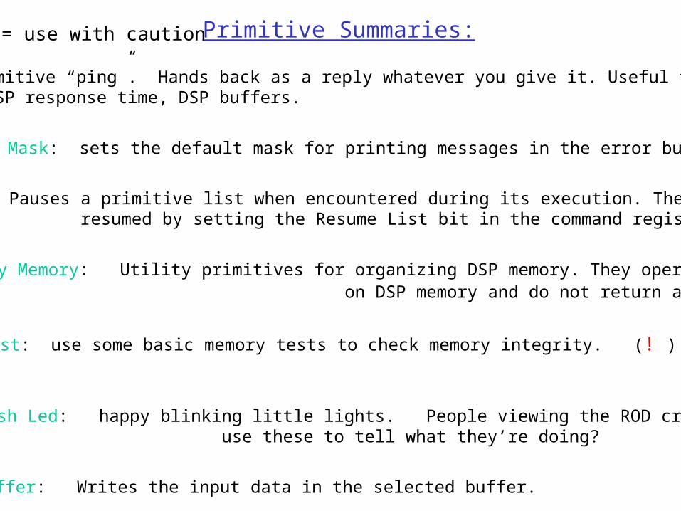
Primitive Summaries:
Echo: a primitive “ping”. Hands back as a reply whatever you give it. Useful for testing DSP response time, DSP buffers.
Set Err Msg Mask: sets the default mask for printing messages in the error buffer.
Pause List: Pauses a primitive list when encountered during its execution. The list can be resumed by setting the Resume List bit in the command register.
Set Memory, Copy Memory: Utility primitives for organizing DSP memory. They operate on DSP memory and do not return any data. (! )
Set Led, Flash Led: happy blinking little lights. People viewing the ROD crates could use these to tell what they’re doing?
Memory Test: use some basic memory tests to check memory integrity. (! )
! = use with caution
Write Buffer: Writes the input data in the selected buffer.
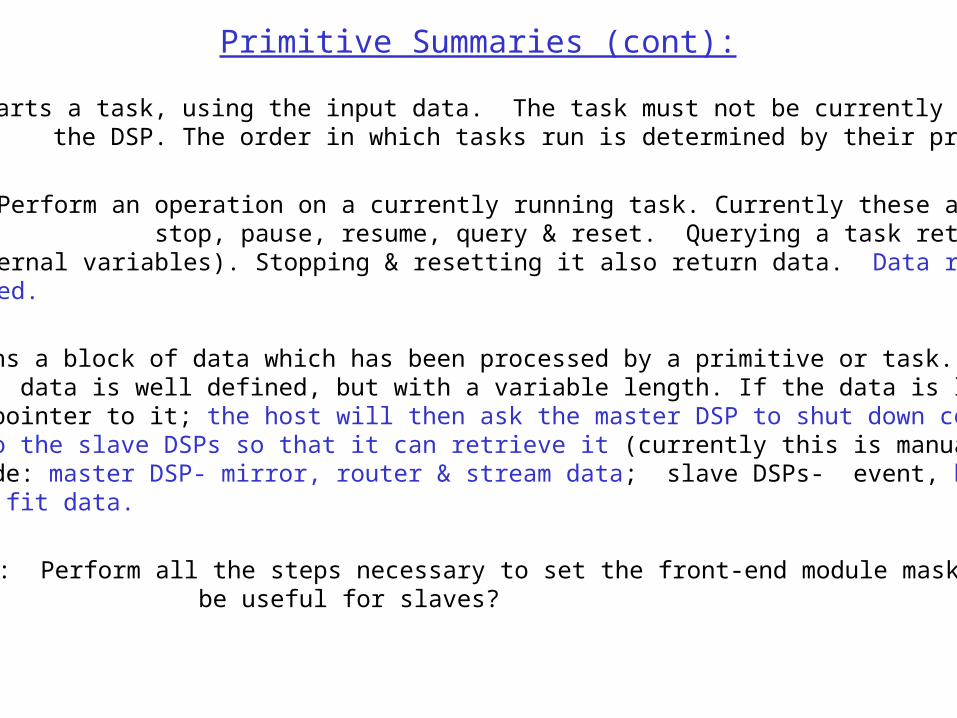
Primitive Summaries (cont):
Start Task: Starts a task, using the input data. The task must not be currently running on the DSP. The order in which tasks run is determined by their priority (input).
Send Data: Returns a block of data which has been processed by a primitive or task. The data is well defined, but with a variable length. If the data is large (histograms), returns a pointer to it; the host will then ask the master DSP to shut down commun- ications to the slave DSPs so that it can retrieve it (currently this is manual). Data types include: master DSP- mirror, router & stream data; slave DSPs- event, histogram, occupancy & fit data.
Module Mask: Perform all the steps necessary to set the front-end module masks. Would it be useful for slaves?
Task Operation: Perform an operation on a currently running task. Currently these are stop, pause, resume, query & reset. Querying a task returns its current data (internal variables). Stopping & resetting it also return data. Data return not fully implemented.
Set Trigger: Being re-vamped. Primitive version of the histogram control task. Differences between them are that set trigger only does a single bin, and can be set to send triggers at an input rate. Also can be run locally on slave DSPs.
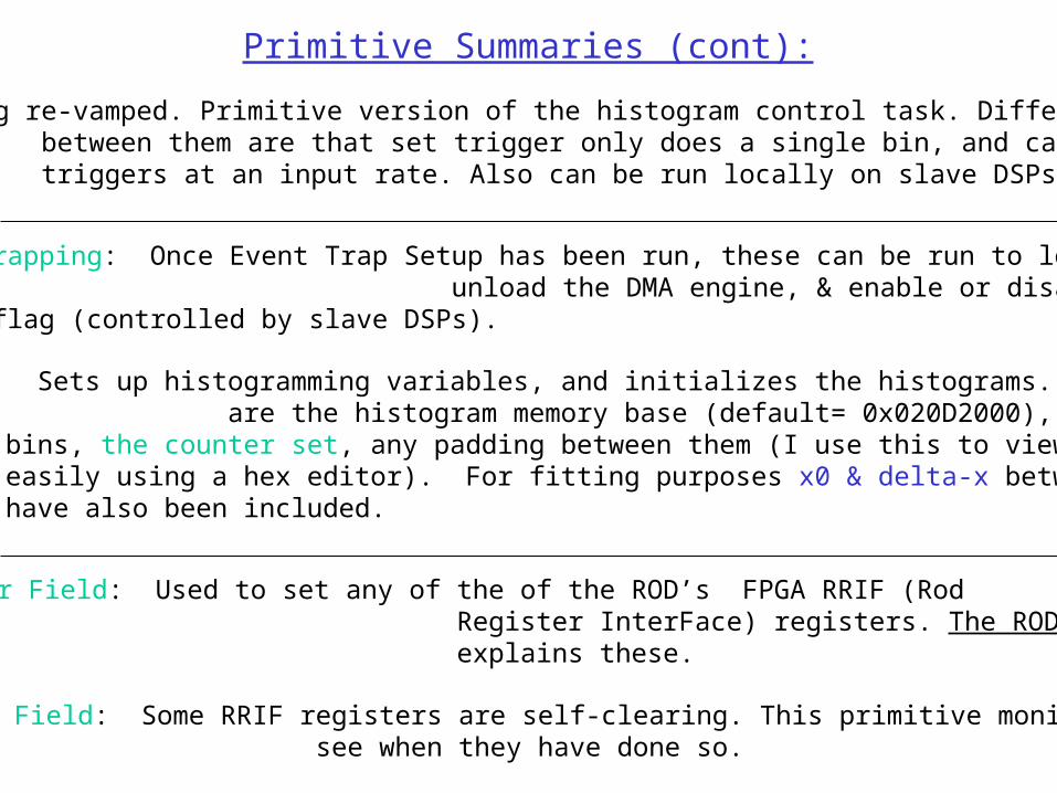
Primitive Summaries (cont):
Start & Stop Event Trapping: Once Event Trap Setup has been run, these can be run to load & unload the DMA engine, & enable or disable the router’s Trap Enable flag (controlled by slave DSPs).
Histogram Setup: Sets up histogramming variables, and initializes the histograms. The inputs are the histogram memory base (default= 0x020D2000), the ROD type, the # of bins, the counter set, any padding between them (I use this to view the histograms more easily using a hex editor). For fitting purposes x0 & delta-x between histogram bins have also been included.
Read & Write Register Field: Used to set any of the of the ROD’s FPGA RRIF (Rod Register InterFace) registers. The ROD Operations Manual explains these.
Poll Register Field: Some RRIF registers are self-clearing. This primitive monitors them to see when they have done so.
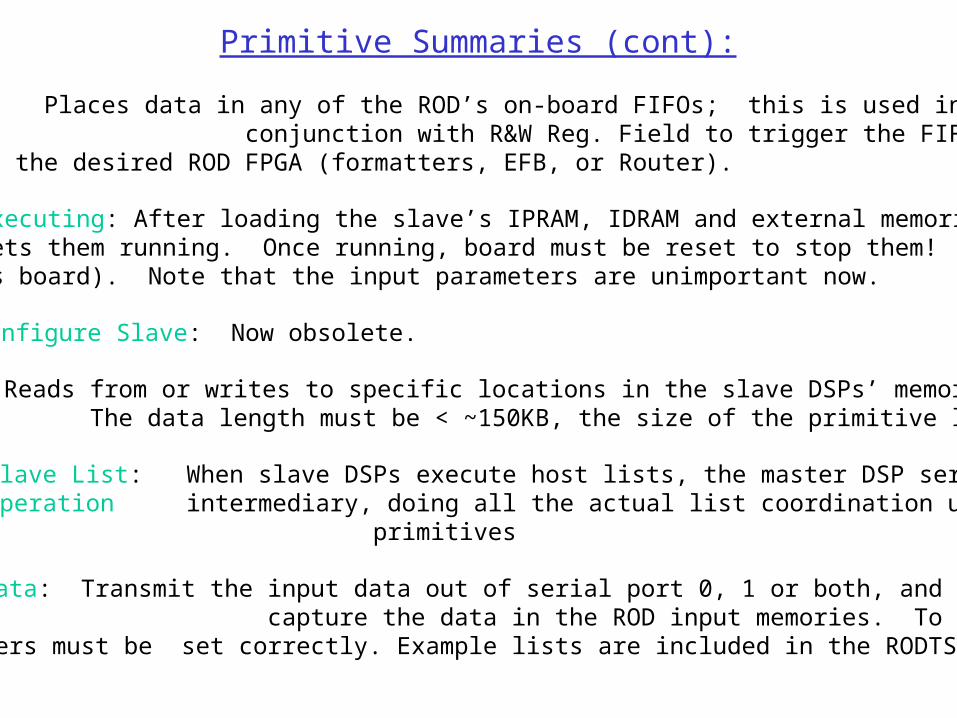
Primitive Summaries (cont):
Read & Write FIFO: Places data in any of the ROD’s on-board FIFOs; this is used in conjunction with R&W Reg. Field to trigger the FIFOs to play their data into the desired ROD FPGA (formatters, EFB, or Router).
Start Slave Executing: After loading the slave’s IPRAM, IDRAM and external memories, SSE sets them running. Once running, board must be reset to stop them! (Standard list resets board). Note that the input parameters are unimportant now.
Configure Slave: Now obsolete.
R/W Slave Memory: Reads from or writes to specific locations in the slave DSPs’ memory. The data length must be < ~150KB, the size of the primitive list buffers. (!)
Send/Start Slave List: When slave DSPs execute host lists, the master DSP serves as theSlave List Operation intermediary, doing all the actual list coordination using these primitives
Transmit Serial Data: Transmit the input data out of serial port 0, 1 or both, and optionally capture the data in the ROD input memories. To work properly, the RRIF registers must be set correctly. Example lists are included in the RODTS setup. (!)
Primitive Summaries (cont):
Build Stream: Build up a command stream from input command/data lists, which can contain up to 4 commands at a time; also used to reset a stream buffer. Command lists contain up to 4 commands, and successive calls will concatenate them. Either of 2 stream buffers can be used, or both if data is to be tramsmitted from both serial ports. Commands can be any of the delay, fast, slow, data or mask commands. The stream buffers are located at: 0: 0x80008000, 1:0x8000B400.
Send Stream: Sends any data contained in the stream buffer(s) out of the requested serial port(s), with optional capture. Needs testing.
Task Summaries:
Event Trapping: Currently this is a stand-alone slave task which simply traps (copies) the desired # of events into the (input) trapping buffer. (A default buffer in high memory is suggested). The router must be set properly beforehand; soon will be modified to cooperate with the master DSP in setting the router’s registers on the fly.
Occupancy counting: Creates occupancy maps for incoming events.
Error counting: Counts & categorizes events with errors.
Link Re-synchronization: Performs whatever corrective actions are necessary to bring links/events back into synchronization when a trigger is dropped.
Memory Mirroring: Mirror the slave DSP’s memory (for example, their communication registers & idata) This task is special in that it can be called multiple times & accumulate up to 6 different slave memory regions to mirror (mirrors are stacked). Needs testing.
Trap Request Monitoring: Monitors the slave DSPs trap request registers; when a request is made sets up that DSP’s router registers appropriately.
Module Configuration
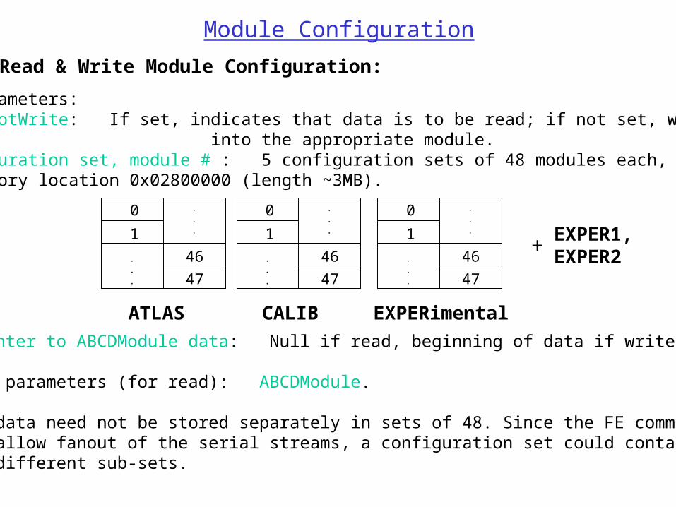
Read & Write Module Configuration:
• Input parameters: readNotWrite: If set, indicates that data is to be read; if not set, write the data into the appropriate module. configuration set, module # : 5 configuration sets of 48 modules each, beginning at memory location 0x02800000 (length ~3MB).
0
1
.
.
.
.
.
.
46
47
ATLAS
0
1
.
.
.
.
.
.
46
47
CALIB
0
1
.
.
.
.
.
.
46
47
EXPERimental
EXPER1, EXPER2+
pointer to ABCDModule data: Null if read, beginning of data if write.
• Output parameters (for read): ABCDModule. •Module data need not be stored separately in sets of 48. Since the FE command masks allow fanout of the serial streams, a configuration set could contain as many as 48 different sub-sets.
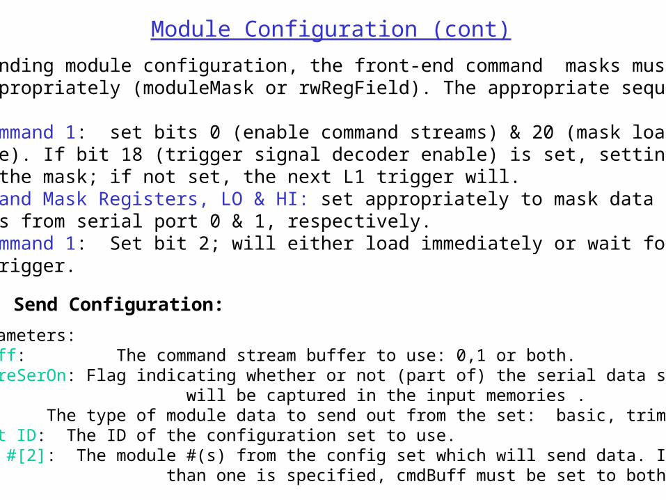
Before sending module configuration, the front-end command masks must be set appropriately (moduleMask or rwRegField). The appropriate sequence is:
1) RRIF Command 1: set bits 0 (enable command streams) & 20 (mask load enable). If bit 18 (trigger signal decoder enable) is set, setting bit 2 will load the mask; if not set, the next L1 trigger will. 2) FE Command Mask Registers, LO & HI: set appropriately to mask data streams from serial port 0 & 1, respectively. 3) RRIF Command 1: Set bit 2; will either load immediately or wait for the next trigger.
Send Configuration:
• Input parameters: cmdBuff: The command stream buffer to use: 0,1 or both. captureSerOn: Flag indicating whether or not (part of) the serial data sent out will be captured in the input memories . type: The type of module data to send out from the set: basic, trim DACs, or all. struct ID: The ID of the configuration set to use. module #[2]: The module #(s) from the config set which will send data. If more than one is specified, cmdBuff must be set to both.
Module Configuration (cont)
Event Trap Setup
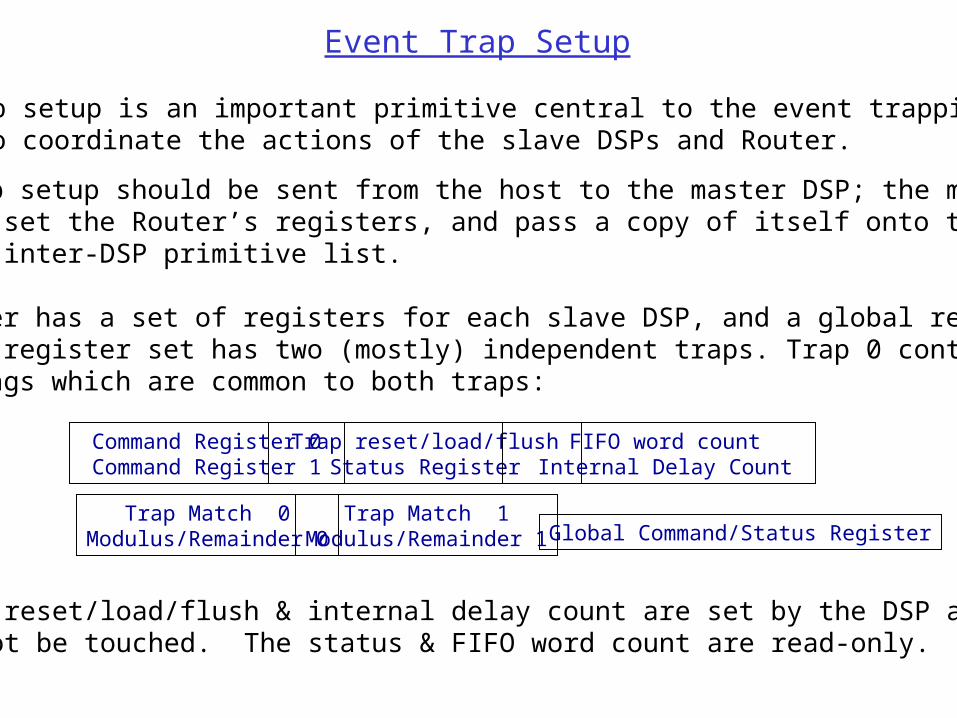
• Event trap setup is an important primitive central to the event trapping; it is used to coordinate the actions of the slave DSPs and Router.
• Event trap setup should be sent from the host to the master DSP; the master will then set the Router’s registers, and pass a copy of itself onto the slave using the inter-DSP primitive list.
• The router has a set of registers for each slave DSP, and a global register set. Each DSP register set has two (mostly) independent traps. Trap 0 contains some Extra flags which are common to both traps:
Command Register 0 Command Register 1
Trap reset/load/flush Status Register
Trap Match 0Modulus/Remainder 0
Trap Match 1Modulus/Remainder 1
FIFO word count Internal Delay Count
• The Trap reset/load/flush & internal delay count are set by the DSP and generally should not be touched. The status & FIFO word count are read-only.
Global Command/Status Register
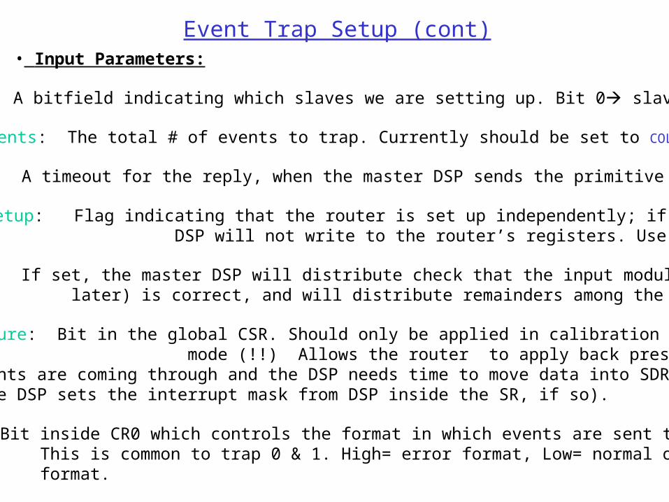
Event Trap Setup (cont)• Input Parameters:
slvBits: A bitfield indicating which slaves we are setting up. Bit 0 slave 0, etc.
# of events: The total # of events to trap. Currently should be set to COLLECT_FOREVER.
timeout: A timeout for the reply, when the master DSP sends the primitive to a slave.
extRouterSetup: Flag indicating that the router is set up independently; if set the master DSP will not write to the router’s registers. Use with care!
distribute: If set, the master DSP will distribute check that the input modulus (described later) is correct, and will distribute remainders among the input slaves.
permitBackPressure: Bit in the global CSR. Should only be applied in calibration mode (!!) Allows the router to apply back pressure to the EFB if large events are coming through and the DSP needs time to move data into SDRAM. (The slave DSP sets the interrupt mask from DSP inside the SR, if so).
format: Bit inside CR0 which controls the format in which events are sent to the DSP. This is common to trap 0 & 1. High= error format, Low= normal or “S-Link” format.

Event Trap Setup (cont)• Input Parameters (cont):
dataMode: Bit inside CR0 which controls the whether the Router (for that DSP) outputs data in event mode (skipping to the end of a frame with a trailer, and writing 0x40ff +length, or in data mode, in which it waits until it has enough data to fill a frame. Common to both traps.
sLink: Bit in SR0; if set the trap match is overridden and only the modulus & remainder of trap 0 are used to distribute events among DSPs. Common to both traps. Probably should use for now. The trap 1 VHDL has not been tested as thoroughly; likewise trapping specific event types needs more testing.
• Trap Input Parameters:
config: The type of events to trap. If IDLE, trap is unused; otherwise ATLAS, ROD or TIM. If sLink is set, Trap 1 should be IDLE, and trap 0 set to SLINK.
exclusionFlag: If set will trap all events *except* those in the match register. NOTE: for now this is common to both traps.
match: The type of event for the router to match.
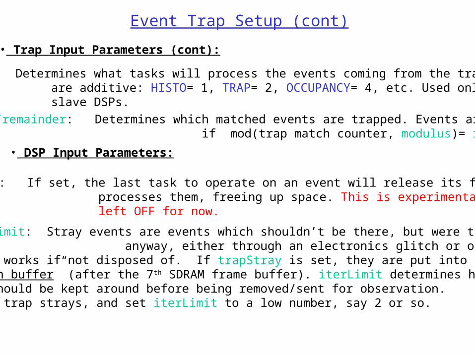
• Trap Input Parameters (cont):
modulus/remainder: Determines which matched events are trapped. Events are trapped if mod(trap match counter, modulus)= remainder.
Event Trap Setup (cont)
• DSP Input Parameters:
releaseFrames: If set, the last task to operate on an event will release its frames as it processes them, freeing up space. This is experimental and should be left OFF for now.
trapStray/iterLimit: Stray events are events which shouldn’t be there, but were trapped anyway, either through an electronics glitch or operator error. They gum up the works if not disposed of. If trapStray is set, they are put into a special “observation buffer” (after the 7th SDRAM frame buffer). iterLimit determines how long they should be kept around before being removed/sent for observation. Suggestion: trap strays, and set iterLimit to a low number, say 2 or so.
function: Determines what tasks will process the events coming from the trap. Functions are additive: HISTO= 1, TRAP= 2, OCCUPANCY= 4, etc. Used only by the slave DSPs.
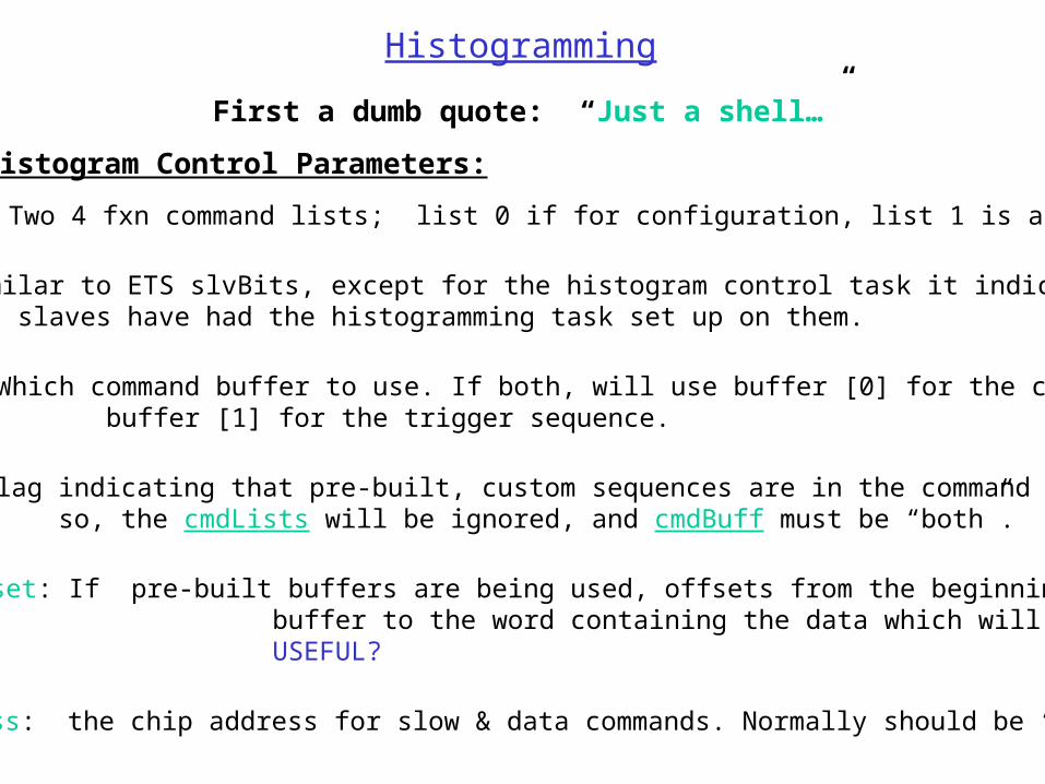
Histogramming
Histogram Control Parameters:
cmdList[2]: Two 4 fxn command lists; list 0 if for configuration, list 1 is a trigger.
slvBits: similar to ETS slvBits, except for the histogram control task it indicates which slaves have had the histogramming task set up on them.
cmdBuff: Which command buffer to use. If both, will use buffer [0] for the config and buffer [1] for the trigger sequence.
preBuilt: Flag indicating that pre-built, custom sequences are in the command buffers. If so, the cmdLists will be ignored, and cmdBuff must be “both”.
preBuiltDataOffset: If pre-built buffers are being used, offsets from the beginning of each buffer to the word containing the data which will be incremented. USEFUL?
chipAddress: the chip address for slow & data commands. Normally should be “all chips”?
First a dumb quote: “Just a shell…”
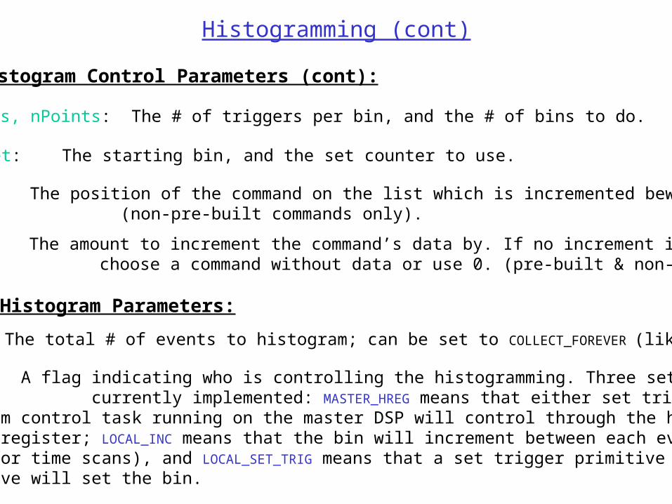
repetitions, nPoints: The # of triggers per bin, and the # of bins to do.
bin0, set: The starting bin, and the set counter to use.
Histogramming (cont)
Histogram Control Parameters (cont):
incCmd[2]: The position of the command on the list which is incremented bewteen bins. (non-pre-built commands only).
incData[2]: The amount to increment the command’s data by. If no increment is wanted, choose a command without data or use 0. (pre-built & non-pre-built).
Histogram Parameters:
nEvents: The total # of events to histogram; can be set to COLLECT_FOREVER (like ETS).
controlFlag: A flag indicating who is controlling the histogramming. Three settings are currently implemented: MASTER_HREG means that either set trigger or the histogram control task running on the master DSP will control through the histogram command register; LOCAL_INC means that the bin will increment between each event (useful for time scans), and LOCAL_SET_TRIG means that a set trigger primitive running on the slave will set the bin.
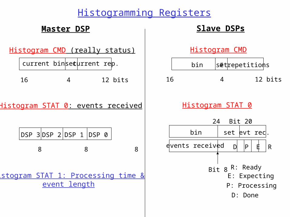
Histogramming Registers
Master DSP Slave DSPs
Histogram CMD (really status)
current bin set current rep.
16 4 12 bits
Histogram CMD
bin set # repetitions
16 4 12 bits
Histogram STAT 0: events received
DSP 3
8 8 8 8
DSP 2 DSP 1 DSP 0
Histogram STAT 0
bin set evt rec.
events received D P E R
R: ReadyE: Expecting
P: Processing
D: Done
Bit 8
Bit 2024
Histogram STAT 1: Processing time &event length
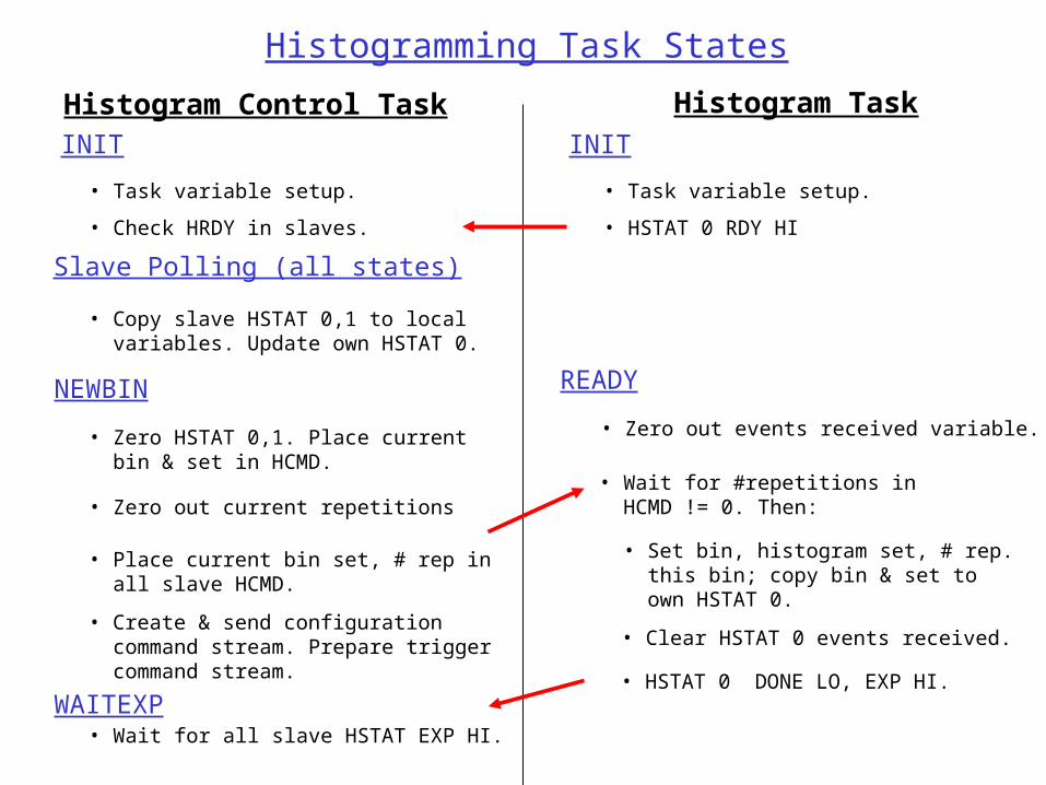
Histogramming Task States
Histogram Control Task Histogram Task
INIT INIT
NEWBIN
• Task variable setup. • Task variable setup.
Slave Polling (all states)
• Copy slave HSTAT 0,1 to local variables. Update own HSTAT 0.
• Zero HSTAT 0,1. Place current bin & set in HCMD.
• Place current bin set, # rep in all slave HCMD.
• Zero out current repetitions
• Create & send configuration command stream. Prepare trigger command stream.
READY
• Wait for #repetitions in HCMD != 0. Then:
• Set bin, histogram set, # rep. this bin; copy bin & set to own HSTAT 0.
• Zero out events received variable.
• HSTAT 0 RDY HI• Check HRDY in slaves.
• HSTAT 0 DONE LO, EXP HI.
• Clear HSTAT 0 events received.
WAITEXP• Wait for all slave HSTAT EXP HI.
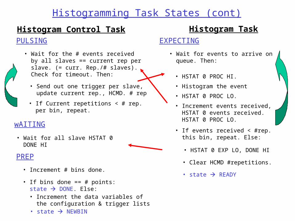
Histogram Control Task Histogram Task
PULSING EXPECTING
wAITING
• Wait for the # events received by all slaves == current rep per slave. (= curr. Rep./# slaves). Check for timeout. Then:
• Wait for events to arrive on queue. Then:
• Send out one trigger per slave, update current rep., HCMD. # rep
Histogramming Task States (cont)
• If Current repetitions < # rep. per bin, repeat.
• Wait for all slave HSTAT 0 DONE HI
• Histogram the event
• HSTAT 0 PROC LO.
• HSTAT 0 PROC HI.
• Increment events received, HSTAT 0 events received. HSTAT 0 PROC LO.
• If events received < #rep. this bin, repeat. Else:
• HSTAT 0 EXP LO, DONE HI
• Clear HCMD #repetitions.
• state READY
PREP
• If bins done == # points: state DONE. Else:
• Increment # bins done.
• Increment the data variables of the configuration & trigger lists • state NEWBIN