Embed Size (px)
Citation preview

ilt,every undergoes24-hour burn-in, then is aligned and tested tomeet or exceed every spec on the data sheet.Which makes us very confidentabout warranting your KWM-380 for one full year.
The result is a radio with superior performance and lasting quality, not front-panel glitter.
Frequency stabil ity is just one example 01 itsbeauty: typically, drift is as low as 10-12 Hz perhour for normal ham shack environments.Other companies haven't matched our performance because they don't match our qualitybehind the panel.
Add some real beauty to your station.See the KWM-380 at your nearest authorized
dealer. Collins Telecommunications ProductsDivision, Defense Electronics Operations,
Rockwell International, Cedar Rapids, IA52498. Phone (319) 395-5963. Telex: 464-435.
, , Rockwell International
At Collins, we know e isettle for less than professional performance.So we build every KWM-380 to commercialrather than amateur standards. For example,our PC boards are connected by ribbon cableswith gold-plated pinlield connectors, The boardsthemselves are all glass epoxy, and virtually
unaffected by temperature and humidity whichcause intermittents in the more commonlyused phenolic boards.
...where science gets down to businessCIRCLE 50 ON READER SERVICE CARD

Table 1- Manufacturer 's specifications.
" 1.7 kHz"360 Hz"140 Hz
Parameter
PhysicalSize
Weight
EnvironmentalOperating temperatureOperating humidityOperatmq alt itudeVibration
EltctricllPrimary cower
RtctiverFrequencyModesSensitivity (Using "sen ltVmeasurement)seecnvev (3 dBbandwidth)
1.1. and image rejectionmterrrecutauon dlslorll()fl
AGe
Audio output
TransmitterFrequency
ModesOutput power
Unwanted signal suppressionCarrierUndesirecl sideband.1 kHz retHarmonics (all)Mixer productsThird order distortion
Synthesizer accuracyand stability
Antenna impedlnce
AudiO inputsMicrophone
line
Say You Saw It In CO
Specifications
394 mm (15.5 in] wide; 190 mm (7.5 in.) high, including25 mm (1 In.) feet; 457 mm (18.0 in.) deep27.2 kg (50 lb.), max
o to 50°C (32 to 122°F)o to 90 % relative humidityo to 3049 m(0 to 10,000 fl. )2 g's, 101033 Hz
Strapoable for: 105, 115. 125121 0. 220, 230, 240. 250 V± 5%, 50 to 60 Hz; or 12 to 15 V oc. negat ive ground'120 watts max in receive. 600 watts max in transmit
0.5 fO 30.0 MHz, tunable in 10 Hz stepsu s.o.. r.s.c.. a.rn.. and c.w.0,5 "V or better lor 10 dB (s + n)ln, 20 to 30.0 MHz,s.s.o. and c.w.; 1.0 "V or better for 1.8 to 2.0 MHz,Selectable:
8 kHz"6 kHz2.1 kHz
"Optional FiltersGreater Ihan 60 dB- 50 dB or better lor two signals of - 10 dB mW each.20 kHz apartAudiO output variation not more than 8 dB lor 4 "V to200 mV open circuit d . input variationNot less than 3 W into 4 ohm load. at 1 kHz. at not morethan 10% tota l harmonic distortionline eucre output not less than - 10 dB mW nominal mto 600 ohmsFrequency response: 300 to 2400 Hz with not more than5 dB variation
160 through 10 m amateur bands. tunable in 10 Hz steps160 m 1.800 to 2,000 MHz80175 m 3.500 to 4.000 MHz40 m 7.000 to 7.300 MHz20 m 14.000 to 14,350 MHz15 m 21.000 to 21.450 MHz10 m 28.000 to 29.700 MHz
u.s.b.. I.s.b.. and c.w (ATTY by AFSK on Ls.b.)90 W pep, min (too W, nominal)In cw or ATTY: 50% duty cycle; key down 15 minutes.max, Automatic turndown to 50 W aller 10 seconds.With optional blower kit installed. power is 100 Waverage. 50% duty cycle, key down 1 hour max at 25°C;30 minutes max at 50° C for all modes,
- SO dB or better
- 55 dB Of better- 40 dB or better- 50 dB or better25 dB below each tone of 2-tone test
Accuracy WIthin :!: 5 Hz after 10 minutes warmup when39.6 MHz and 455 kHz oscillators are set to Within± 3 Hz.Stability within :!: 150 Hz over temperature range of 0 10so oC (32 to 122°F) if osci llator's set within 10 Hz at25°C (77°F)
50 Ohms. ncoreecuve. (Full transmitter power outputWith v.s.w.r. 012:1 or less. Automatic power output turndown with v.S.w.r. greater than 2:1.)
low or high impedance. dynamic; 3.3 kG nominal impedance600 Ohm, unbalanced: 40 mV inpul sufficient lor lull r.t .power output
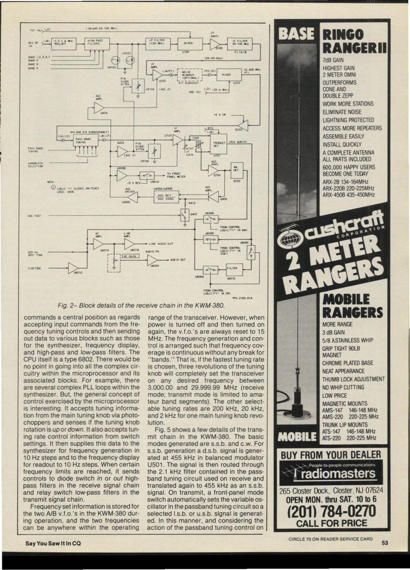
various specific functions. An examinetion o f slightly more deta iled receive andtransmit signa l path block diagramsshould he lp to c larify the situation .
For instance , f ig . 2 shows deta ils of thereceive signa l pa th. The "front-end" ofthe KWM-380 is unique in several reospects. There is no r.I. ampuner stage,and there are none of the usual bandpassf ilters as are usually associated even withtransceivers having a " h igh" first i.t.(above 30 MHZ). The t ilter b locks that anincoming signa l goes through before being amplified are not quite w hat onewould expect . The first filter block is a0.5- 1.6 MHz rolloff one, simply designedto protect the transceiver from BC bandove rload. The t nqn-passurter block worksin conj unction with a fo llowing 30 MHzrow-pass f ilter b lock. The latter is f ixed infrequency at 30 MHz, while there is a selec tion of three h igh-paSS fi lter cutoffs ofabout 20, 14, or 7 MHz. So. an incomingsignal can be "bracketed" between 7-30MHz, 14-30 MHz, or 20-30 MHz.
The reason for this arrangement is notSimp ly to provide image signa l rejection;the very high f irst U . frequency takescare o f that. The h igh-pass fi lters ensurethat the transceiver does not generatesecond order intermodu lation productsof com me rcialfbroadcasti ng stations.For instance, in the European area the" breakth rough" of 13-15 M Hz signa ls on" s imp le " transceivers operating on 10meters can be a very severe problem.The problem doesn't ex ist with theKWM·380. In between the high- and lowpass filter blocks one can see a PIN diodeattenuator (CR104). This d iode is controlled by a voltage from a.a.c. amplifiersin the KW M-380. Essentia lly. the diodeperforms the same func t ion in an automatic fashion as the manual r.f. attenuator switches one f inds on many h.f . transceivers.
The 39.1 45 MHz i.f . signal is producedby the fi rst "U100" mixer. This U. signalis amplified , passes through an optionalnoise blanker unit. and then goes on tomixer " U 102," where the i.I. signal istranslated to 455 kH z and routed to apassband tuning assembly. An up/downfrequency translation takes p lace in thisassembly in that the 455 kHz i.t. is translated toan i.I. of 6.255 MHz and then backdown aga in to 455 kHz. True signal setect ivity takes place in crystal filters associ·ated with the 6.255 MHz U . The final 455kHz U. signal is demodulated to providean audio output and rectified to providethe cont ro l voltage for an elaborate" hang" a .g.c . loop w hich controls boththe incoming signal attenuation (PIN or.Odes between the h igh-pass and lowpa ss f ilter b locks) and the f inal 455 kHz i.f.signal attenuation (PIN dicx:les before the" U700" stage shown in fig. 2). The 800 HzSpot Tone input shown in the lower letthand corner of fig . 2 provides for a convenience teature. in that in the cw. modeonly. one can enable an 800 Hz lest lone
November1982 • CO • 51
•
,
,
"'0-'
~'>-+-I, >---<50--.1..... "'" Il-xr·-r
_.0[".0"'"
"'"''
... ' ., .......
0"
, ,,,r >• .eM
"",, ", t .OC"" "vt.
_ 0 •••
_..-.."..
.,-0----i .........' It'I
...... " .'~DO '0.''' " ....
••
.... co. _.... " 0_ . , . ... . .. ' 0" ••
..........'•
u.,....~..."'"ft01
" 'l! :<I ~. , •• ot _ ..... """"- •• •-- ~ ....
L~ ....,....,. j
I _ "0 .' ''''''- _ .. S°""'-
O "'Ta' 0 0
' "
-v--- - <2) """ ',"',,"
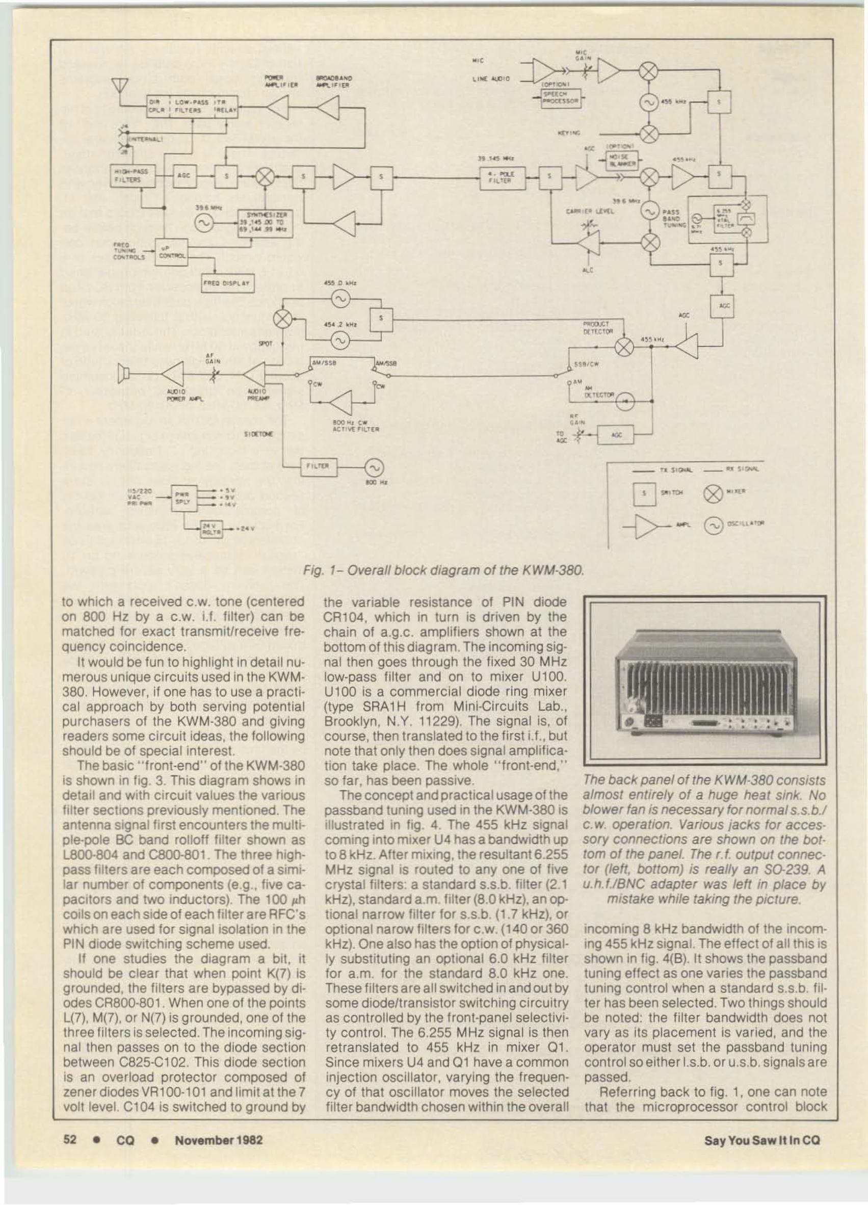
Fig. 1- Overall block diagram of the KWM-380.
to which a received c.w. tone (centeredon 800 Hz by a c.w. i.f. filter) can bematched for exact transmit/receive frequency coincidence.
II would be fun to highlight in detail numerous unique circuits used in the KWM380. However, if one has to use a practical approach by both serving potentialpurchasers of the KWM-380 and givingreaders some circuit ideas, the foHowingshould be of special interest.
The basic " front-end" of the KWM-380is shown in fig. 3. This diagram shows indetail and w ith circu it va lues the variousfilter sec tions previously mentioned. Theantenna signal f irst encounters the multi p le-pole Be band rouot t fi lter shown asL8lJO.804 and C80().801 . The three high·pass fillers are each composed of a similar number of components (e.g., f ive capacitors and two inductors). The 100 phcoils on each side of each filter are RFC'swhich are used for signal isolation in thePIN diode switching scheme used.
If one studies the diagram a bit , itshould be c lear that when point K(7) isgrounded, the fillers are bypassed by diodes CR800·801 . When one of the pointsL(7), M(7), or N(7) is grounded, one of thethree filters is selected. The incoming sig·nal then passes on to the diode sectionbetween C825-Cl02. This diode sectionis an overload protector composed ofzener diodes VR100-101 and limit at the 7vonrevet. C104 is switched to ground by
the variable resistance of PIN diodeCR104, which in turn is driven by thechain of a.g.c . amplifiers shown at thebottom of this diagram. The incoming signal then goes through the fixed 30 MHzlow-pass filter and on to mixer U 100.U100 is a commercial diode ring mixer(type SRA1H from Mini-Circuits Lab.,Brooklyn, NY. 11229). The signal is, ofcourse, then translated to the first i.L. butnote that only then does signal amplification take place . The whole "front-end,"so far, has been passive.
The concept and practical usage of thepassband tuning used in the KWM-380 isillustrated in fig . 4. The 455 kHz signalcoming into mixer U4 has a bandwidth upto 8 kHz. Aller m ixing , the resultant 6.255MHz signa l is routed to anyone of f ivecrystal filters: a standard s.s.b. fi lter (2.1kHZ), standard a.m. filter (8.0 kHz), an optional narrow filler for s.s.b. (1.7 kHz) , oroptional narow filters for cw. (140 or 360kHz). One also has the option of physically substituting an optional 6.0 kHz filterfor a.m. for the standard 8.0 kHz one.These filters are all switched in and out bysome orode.transistor switching circuitryas cont rolled by the front-panel selectivity control. The 6.255 M Hz signal is thenretranslated to 455 kHz in mixer 01.Since mixers U4 and 01 have a commoninjection oscillator, varying the trequency of that oscillator moves the selectedfilter bandwidth chosen within the overall
The back panel of the KWM·380 consistsalmost entirely of a huge heat sink. Noblower fan is necessary for normal s.s.b./c.w. operation. Various jacks for accessory connections are shown on the ocrtom of the panel. The r. f. output coooector (left. bottom) is really an S0-239. Au.h.f.lBNC adapter was left in place by
mistake while taking the picture.
incoming 8 kHz bandwidth of the incoming 455 kHz signal. The effect of all this isshown in fig. 4(8). It shows the passbandtuning effect as one varies the passbandtuning control when a standard s.s.b. fil·ter has been selected. Two things shouldbe noted: the filter bandwidth does notvary as its placement is varied, and theoperator must set the passband tuningcontrol so either l.s.b. or u.s.b. signals arepassed.
Referring back to fig. 1, one can notethat the microprocessor control block
52 • CO • November 1982 Say YOUS8W It InCa
.... 11"·01 .
70B GAINHIGHEST GAIN2 MffiR OMNIOlITP£RFOOMSCONE ANDOOUBlE ZEPI'VvOOK MORE STATIONSBJMINATE NOISElIGHTNING PROTECTEDACCESS MORE REPEATERSASSEMBlE EASILYINSTAlLQUICKLYA COMftETE ANTENNAALL PARTSINCLUDED600,000 HAPPY' USERSBECOMEONE TOCiWAAX-2B134 -164MHzARX-220B220-225MHzAAX-45OB 435-450MHz
RINGORANGERII
MORE RANGE3 dB GAIN5/8 ASTAINlfSS INHIPGRIPTIGHT!lll.BMAGNETCHROMEPLATED BASeNEAT APPEARANCETHUMB lOCK ADJUSTMENTNO YJHIP CUTTINGLlJN PfUCEMAGNETIC MOONTSAMS-147 146-148 MHzAMS-22O 220-225 MHzTRUNK UP MOUNTS,4JS-147 146-148 MHz,4JS-22O 220-225 MHz
MOBILERANGERS
,,"" ,People 10 people communoCahon ,
, "
BUY FROM YOUR DEALER
265 Closter I:XJck , Closter,NJ 07624OPEN MON. thru SAT. 10 to 6
(201)784-0270CALL FOR PRICE
range of the transceive r. However, whenpower is turned off and then turned onagain, the v.t.o.:s are always reset to 15MHz . The frequency generation and control is arranged such that frequency coverage is continuous without any break for"bands." That is, if the fastest tuning rateis chosen . three revolutions of the tuningknob will completely set the transceiveron any desired frequency between3.000.00 and 29.999.99 MHz (receivemode; transmit mode is limited to amateur band segments). The other selectable tun ing rates are 200 kHz. 20 kHz,and 2 kHz for one main tun ing knob revolution.
Fig. 5 shows a lew details of the transmit chain in the KWM-380. The basicmodes generated are s.s.b. and c.w. Fors.s.b. generation a d.s.b. signal is generated at 455 kHz in balanced modulatorU50 ' . The signal is then routed throughthe 2.1 kHz filter contained in the passband tuning circuit used on receive andtranslated again to 455 kHz as an s.s.b.signal. On transmit, a front-panel modeswitch automatically sets the variable oscillator in the passband tun ing ci rcuit so aselected I.s.b. or u.s.b . signal is generated. In this manner, and considering theaction of the passband tun ing control on
.., e....... ' .. _ ,
".~..~ " '- , ..... I- .,..., .... .......1'£11 - ' " ""[II -~. ""... ,,,,, -, ..... .. ,..-... --<-.
'coo,•.'. 1. '" I I
E .~ ..... _,..- -T r-.:.. ,,,,,,,,, r :.,-:-. - -:':~ '0.- _~ .._ - """"+ ••• " ,... ' ' '''''-''',,~
t..- l.. _____ .. _...~ ."_....
.~ , ..x » • .d ' , • • _~ ..
~
L T;:'v_
••• CO
J-..>,~ , -"'-..,_... __., -,..."" ,""J' ". <,
. ... e-J jr"..... - ... - ' ,,",", """ 0 )-[>.;- . ~ k .''.I I ' . n ", .,..., ..,., ,"" " ..0-
r <10100 '* ."..~""
K- •.,-C. m ,...., v.~v ....., ..".
." •f. ",,,-I """" ..G> "",,< -,- <I..... "" f<H<' ~ - ~- - ....;.,.. - A
&"" on ::J--- " -..... "
r --,Lt- .'-,
L ~- Q)o-UIOocr." .. _ ,• ... -.r- - I-I~
[1;_. .... ..- ...... -V _ L·-- J-""0(1 • • ,..'" ~,...,--~ I ... SO" I
~ ,, [2-""'" OJ'
,r-,
,, ,, , _.
~,,--'I- " ~ l-V- l __ "": ,- -
~,,,,.,,
.... .T,." ...
commands a cent ral position as regardsaccepting input commands from the frequency luning cont rols and then sendingout data to various blocks such as thosefor the synthesizer . frequency display,and high-pass and low-pass filters. TheCPU itself is a type 6802. There would beno point in going into all the complex circuitry within the microprocessor and itsassociated blocks. For example. thereare several complex PLL loops with in thesynthesizer. But. the genera l concept ofcontrol exercised by the microprocessoris interesting. It accepts tun ing information from the main tuning knob via photochoppers and senses if the tuning knobrotation is up or down. It also accepts tuning rate control information from switchsett ings. It then supplies this data to thesynthesizer for frequency generation in'0 Hz steps and to the frequency displayfor readout to ' 0 Hz steps. When certainfrequency limits are reached, it sendscontrols to d iode switch in or out highpass filters in the receive signal chainand relay switch low-pass fillers in thetransmit signal chain.
Frequency set information is stored forthe two AlB v.f.o.'s in the KWM-380 during operation, and the two f requenc iescan be anywhere within the operating
Fig. 2- Block details of the receive chain in the KWM-38D.
.'Of''''
•••'...' ,
----. ... 'c .. ,· .. CO '
•
Say You Saw liin COCIRCLE 70 ON READ£R SERVICE CARD
53
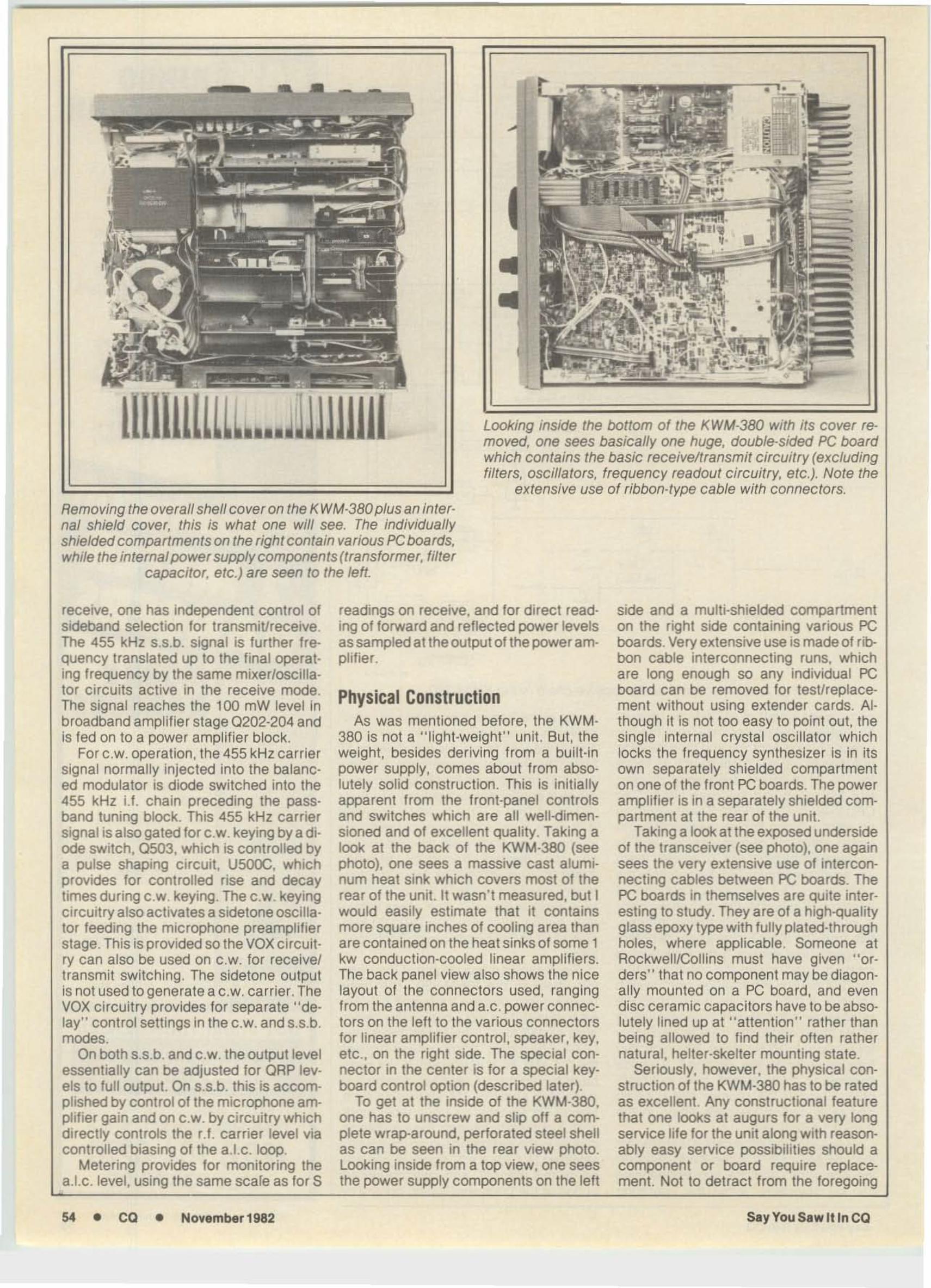
Looking inside the bottom of the KWM-380 with its cover removed, one sees basically one huge, double-sided PC boardwhich contains the basic receive/transmit circuitry (excludingfilters, oscillators, frequency readout circuitry, etc.). Note the
extensive use of ribbon-type cable with connectors.
Removing the overett shell cover on the KWM-380 plus an internal shield cover, this is what one will see. The individuallyshielded compartments on the right contain various PCboards,while the internal power supplycomponents (transformer, filter
capacitor, etc.) are seen to the left.
receive, one has independent control ofsideband selection lor transmttrreceive.The 455 kHz s.s.b. signal is further Irequency translated up to the final operating frequency by the same rnixerroscltlator circuits active in the receive mode.The signal reaches the 100 mW level inbroadband amplifier stage 0202-204 andis fed on to a power amplifier block.
For c.w. operation, the 455 kHz carriersignal normally injected into the batanced modulator is diode switched into the455 kHz i.t. chain preceding the passband tuning block. This 455 kHz carriersignal is also gated for c .w. keying by a diode switch. 0503, which is controlled bya pulse shaping circuit, U5OOC, whichprovides for controlled rise and decaytimes during c .w. keying. The c .w. keyingc ircuitry also activates a sidetone osciuator feeding the microphone preamplifierstage. This is provided so the VOX circuitry can also be used on c.w. for receive/transmit switching. The sidetone outputis not used togenerate a c.w. carrier. TheVOX circuitry provides for separate "delay" control settings in the C.w. and s.s.b .modes.
On both s.s.b. and c.w. the output levelessentially can be adjusted for ORP levels to full output . On s.s.b. this is accomplished by control of the microphone amplifier gain and on c .w. by circuitry whichdirectly controls the r.f. carrier level viacontrolled biasing of the a.l.c. loop.
Metering provides for monitoring thea.l .c. level, using the same scale as for S
54 • CO • November 1982
readings on receive, and for direct reading of forward and reflected power levelsas sampled at the output of the power amplifier.
Physical ConstructionAs was mentioned before, the KWM
380 is not a "light-weight" unit. But, theweight, besides deriVing from a bultt-lnpower supply, comes about from absolutely solid construction. This is initiallyapparent trom the tront-panet controlsand switches which are all weu-dimenstoned and 01 excellent quality. Taking alook at the back 01 the KWM-380 (seephoto), one sees a massive cast aluminum heat sink which covers most of therear 01 the unit. It wasn't measured, but Iwould easily estimate that it containsmore square inches 01 cooling area thanare contained on the heatsinks of some 1kw conduction-cooled linear amplifiers.The back panel view also shows the nicelayout 01 the connectors used, rangingfrom the antenna and a.c. power connectors on the left to the various connectorsfor linear amplifier controt. speaker, key,etc. , on the right side. The special connector in the center is lor a special keyboard control option (described later).
To get at the inside of the KWM-380,one has to unscrew and slip off a complete wrap-around. perforated steel shellas can be seen in the rear view photo.looking inside from a top view, one seesthe power supply components on the left
side and a multi-shielded compartmenton the right side containing various PCboards. Very extensive use is made of ribbon cable interconnecting runs, whichare long enough so any individual PCboard can be removed for test/replacement without using extender cards. AI·though it is not too easy to point out, thesingle internal crystal oscillator whichlocks the frequency synthesizer is in itsown separately shielded compartmenton one of the front PC boards. The poweramplifier is in a separately shielded compartment at the rear of the unit.
Taking a look at the exposed undersideof the transceiver (see photo), one againsees the very extensive use of interconnecting cables between PC boards. ThePC boards in themselves are quite interesting to study. They are of a high-qualityglass epoxy type with fully plated-throughholes, where applicable . Someone atRockwell/Collins must have given "orders" that no component may be diaqonally mounted on a PC board, and evendisc ceramic capacitors have to be absolutely lined up at "attention" rather thanbeing allowed to find their often rathernatural, netter-sketter mounting state.
Seriously, however, the physical construction of the KWM-380 has to be ratedas excellent. Any constructional featurethat one looks at augurs for a very longservice life for the unit along with reasonably easy service possibilities should acomponent or board require replacement. Not to detract from the foregoing
Say You Saw It In CO

" I.-
"
•-"-----,,~r
,..~
,.-
.-
,!h,.~ i;·
,
.-.
· "
,• • • • •
_.· ,;~
•
••
c·l_,.e..:'--J
• >
::.-~
.- • •.,.-;J\.'--.- ~
,Yo" >,• .~ ••• •
, . ,
•.~ ~, t '--
~ ~ .'
.1
•
,
erating placements subject to conditionssuch as a heavy sart-water-Iaden atmosphere give rise to possible problems. Theother point-an extremely minor one tobe sure-concerns the microphone input jack. It requires a special PJO-68 plug
•
•,•
",:~:,
•
I.! . I~ ~ I, . ,
l I --,..f-1o- ••• •:c ~.-"-,'----.J.-
••
,
•w• •,w•
• •
------'
r~~ ~
'", ., -....
Fig. 3- Unusual "tront-ena" circuitry used in the KWM·380.
111, I,.
,.••
,
but yet to give the reader a complete picture of the KWM-380, one should mentiontwo things. If one is going to use theKWM·380 under extreme environmenta lconditions, one has to take note of theperforated covering used. Obviously, op-
Brings ,ou theBreakthroughl
Prices and Specifications subject tochange without not ice or obli gation.
Software copyright by AEA.
AEA once again breaks newground in the code communication s field with thenew model MBA-RC reader/code converter. The MBA·RCdecodes Morse, Baudot orASCII signals off the air anddisplays them on a large 32character alphanumeri cvacuum fluorscent display. Inaddition, it will output Morsecode for keying your transmitter. It will also generate RTTY(Baudot or ASCII AFSK twotone output. (170 or 850 Hzshifts.) Any of the acceptableinput codes can be convertedto any of the specified outputcodes (any speed to anyspeed). If yo u have any of thecommo n Baudot ATTY terminal s as an example, youcan now send and receiveMorse and ASCII with yourkeyboard and printer. You caneven generate ASCII o rBAUDOT Rny using yourMorse hand key or memorykeyer.
Get the details. Write for ourfree product catalogue or bet·ter yet , see your favo ritedealer.
ADVANCED ELECTRONICAPPLICATIO NS, INC.P.O. Box C·2160,Lynnwood, WA 98036(206) 775-7373Telex: 152571 AEA INTL
FLEXIBILITY
56 CIRClE nON REAOER SERVICE CARO Say You SIlw It InCa

tton that the KWM-380 will deliver a good100 watts output over all of the amateur
Fig. 4- (A) Basic passband tuning scheme used in the KWM-380. (B) An illustration ofhow an incoming signal is affected.
lewl ICW) lewl
"OMI"A~1!lli , ~ / , ~ / , ~ /
~~~~g~ 1u;.~lO'''-IUSBl (U;B~(O':-IUS" 1U;.~"'O':-Il)SBl
bands. It probably could be adjusted toprovide 1Y2 times that power level andfor normal s.s.o. operation would run justas cool. There is no fan included in thestandard KWM-380, nor is one neededfor norma! c.w. or s.s.b. operation thanksto the huge PA neatstnk on the rear of theunit. For AFSK RTTY operation over extended periods, there is an optional blower kit available whic h allows 100 wattsaverage output w ith a 50% duty cycle tobe maintained for one hour under keyedconditions! The power amplifier stagecontains all sorts of protective circuitry,including the usual thermal and S.W.r.
protection. It also contains a rather different fo rward power averaging ci rcuit. Thiscircuit senses forward powe r with a longtime constant. If the forward power averages too high for too long, it activatesa.r.c. ci rcuit ry to reduce the PA output insteps down to 20 watts. Output spuriousproducts, including harmonics, we re atways below - 50 dB and sometimesranged down to - 70 dB.
Howeve r, the most interesting aspectof the transmitted signal was the thtro-order IMD products. They measured - 32to - 35dB from PEP using a two-tone testsignal. So, for all practical purposes, theKWM-380 IMD products are as good asany 100 watt class power amplifier usingthe ubiquitous 61 46B tubes, and there isno tuning. The KW M-380 contains an internal power supply whic h can be strapped for input voltages ranging, in steps,from 105 to 250 volts. It can also operatedirectly from a 12-15 v.d.c. source. Using the latte r, about 3 amperes are drawnin the receive mode and up to 18- 20 amperes for 100 watt c.w.ls.s.b. operation.
0." _
..J I I I
.-262 '.265 ',258
.~U,"-l,J'C . '"
,1,• .252 ' .255 ' .258
. ... ..OWlor.. oFSE~ECTEO FILTER>CE..TEREDABOUT G,:I'!6 M".
I..' .1
(A)
...,.,..., "..,..,-
I
u ,_
L- - - -1 °." .,.."" ...=
••• 'H,
--------+-
. 55 k...~fECE I V( lf
~IG"A~
, ,,6 .262 G.:I'§Ij '-2S9
NDTTOSCA~E
"" oat '''''''
fai rly common in military and commercialcommunications spheres but practic allyunused by radio amateurs. It has beenthe standard Collins plug for many years.
Test ResultsTable I gives the claimed specifica
tions for the KWM-380. To say the leastafter bench testing a unit, one should reogard them as very conservative if notdownright deliberately understated.
On the receive side, the KWM-380greatly exceeded almost all of its claims.The sensitivity ranged around the 0.3 to0.4 microvolt range for 10 dB STN/N ratioon s.s .b. throughout its tuning range.However, much more significant was theexcellent dynamic range. The thi rd orderintercept point for 20 kHz spaced signalsplotted consistently out in the range of+ 14 to + 18 dBm(usuallythe latter). Thesynthesizer noise floor could hardly befoun d with the test equipment available.An educated estimate has to remain atbett er than - 100 dB.
The synthesizer design is undoubtedly
a big part of the secret of the KWM·380'sperformance. Among other things, it allows the excellent shape factor of thes.s.b. filte r to provide meaningful resultsin practice. The stability was only measured at room temperature rathe r thanover the temperatu re range specified. Avariation of only a few Hertz could be discerned over an operating period fromturn-on to an hour or so later. 1.1. and image rejection exceeded 70 dB. And,where did all the "birdies " and spu riousresponses go that one often accepts asbeing normal with amateur radio equipment designs? I got tired of searching fo rthem. Perhaps there are a few of mini-mi.crovolt proportions someplace, but certainty none are apparent. The 5 meter requires about 100 microvolts to indicate59. This is more than the 50 microvoltstandard for 59 frequently used, but ofmore importance is that the 5 meter response of the KWM-380 is tinear w ithin afew dB as signal levels change. 50, onecan provide a meaningful report to anot her station when testing antennas, aud iodevices, etc.
On the tr ansmit side, there is no ques-
Operating ImpressionsAs was mentioned befo re, the trans
ceiver is reset to 15.000 .00 MHz when itis turned on. So, one first sees those digits appear rathe r impressively in thei r approximate 1 inch height above the maintuning knob. The g roup of push buttonsabove the knob controls the tuning rate,locks-out the tuning knob from changingthe frequency whic h has been set, andcan be used to synch ronize the frequencies of the two built-in v.t.o.:s. Once onegets used to the rather strange symbolsused for the tuning-rate buttons, it israther easy to set up for operation , for example, on 21.195.00 MHz. One pressesthe '" button for 1 MHz increments andturns the tuning knob less than a full turnuntil a reading of about 21 MHz appears.One then would normally press one of ther buttons for a 20 kHz/knob revolutionrate to quickly finalize the frequency at21.195.00 MHz. It takes longer to writeabout it or to read about it than it takes toaccomplish it.
The Mode swi tch is used to select thedesired transmit mode, and the Passband
Say You Saw It In CO November 1982 • CO • 57

""'''''·01<
IS' ""T""..•~>- ' .so ...., J' 1; "'"'" ,"" ,,..,..."" .." ... "",
.1 " .,.,'-- ""
>c ,."
VOX ci rcuitry is very handy to set up forsemi-QSK operation on c.w. Used for normal s.s.b. or c .w. operation, the transceiver will run " cool" indefinitely. Thereis no cooling needed (except for extended RnY ope ration), so operation is perfectly quiet.
Accessory ItemsThere is an extensive line of optional
and accessory items available for theKWM-380. The internal mount optionalitems include WARC conversion, variousLt. fillers, a noise blanker, a speech processor, and a contro l interface. The out.board accessory items range all the wayfrom different types of microphones andheadphones to a blower kit fo r the heatsink. Some items have been mentioned inpassing before, so only a few will be covered in detail.
The WARC conversion consists of replac ing an ROM IC on a PCB within thetransceiver. The conve rsion requires theremoval of some 39 screws to get at therequired PC board. Some versions of thePC board have the IC socketed and somedo not. So. the conversion either can beextremely simple or require a bit of soroering. In any case, the conversion willresult in the frequency coverage changeshown in Table II. Note that the conversion not only provides for WARC coverage, but also expands the 80-15 meterbands for MARS transceive coverage.
The optional speech processor available for the KWM·380 is of a completelynew design and a patent is pending on it.It is an audio processing type, but hardlya simple compressor or clipper. In its lit.erature. Collins concedes that the cener-
\ '
'L...1 (::Jr - - - - - - - - - - 'o .... ,." ,... .,-it-
." ,
,"e-".""
..
'" """' OC '~
C' , . ,,,, ,,,..
Fig. 5- Block de /ails of the transmit chain in the KWM-380.
out. The sensation of using the main tuning knob to continuously tune is quitesomething. When one tunes from an indicated 5.999.99 to exactly 6,000.00 MHzthe fi rst few times, one expects all sortsof relays to resound, etc. In fac t, all isquiet and "bands" for the operator in apractical sense no longer exist.
The audio quality produced by thefront-panel-mounted speaker is perfectlyadequate for normal station operationand obviates the need for any accessoryspeaker (none is offered for the KWM·380). The various optional filters providefor just about any selectivity problem.But, one must face the fact that the KWM·380 does not offer true va riable bandwidth Lt. tuning nor a notch filter. Are theynecessary? I would say no if one purchases the various optional filt ers avatlable for the KWM·380, but of cou rse, thisdoes become a pr ice question.
On t ransmit the KWM·380 consistentlyproduced comments regarding its goodaudio quality. It has signal " punch" butwith a "clean" sounding audio, used either in its basic configuration or wi th itsoptional speech processor (describedunder accessories). Perhaps one reasonfor this is its shaped frequency responseof 300 to 2400 Hz on transmit with only afew dB's level variation within that passband. Another reason is undoubtedly thesophisticated a.l.c. system used, whichkeeps the average to peak level powerleve l output closely linked.VOXoperationwas very smooth . Cw. operation was nottried as extensively as s.s.b. operation,but the KWM·380 appears to be as excellent a c.w. transceiver as an s.s.b. one.The separate C.W. Delay cont rol on the
" u,. >ELtct ===========~ Ju""" ..."" , " -.< , '" -",4> -'<, - -
.",Tuning/Selectivity control is set to the desired receive sideband and i.t. bandwidth. There is nothing more to set up ortune on the transceiver, and it is "readyto go" assuming that one has previouslychosen VOX or MaX (PIT) mode, a.g.c.speed, speed processor in/out, etc. If onehas to adjust an antenna tuner, the Modeswitch on the KWM-380 can temporarilybe set to CW and the Mic/Carrier level control used to increase carrier output whilethe reversed power reading is observedand the antenna tuner is adjusted for minimum indication.
The tuning "feel " of the ma in tun ingknob is extreme ly good. It feels slightly" heavy," yet turns easi ly. The otherknobs are also very well dimensioned.For instance, the concentric AF/RF Gaincontrol knobs are not the disaster foundon some receivers. The RF Gain knob canreadily be manipulated, which c.w. buffsshould greatly appreciate.
If one set up the transceiver as mentioned for 21 .195.00 MHz (with the v.r.o.switch at A) and then suddenly remembered a net on 3.897.50 MHz, it's a simplematter to set the v.f.o. switch to a, switchin the appropriate tuning rate buttons,manipulate the main tuning knob a bit ,and be set up on 3.897.50 MHz. One canthen switch back and forth between thev.f.o. Aand a settings for actual operationor for just monitoring purposes. Thev.to:s can also be set so one controlsonly the transmit frequency. In otherwords, half-duplex operation can be carried on between any two amateur bands.If one presses the Sync button, the twov.t.o. frequencies align themselves, yetone can be used to control transmit andthe other to control receive. In fact, thiscan be used as a very sophisticated RIloption since the digital display will indicate the exact transmit/receive frequencies and one has independent tuning ofeach. One only has to remember that theKWM·380 will transmit in the s.s.b . modeas set by the Mode switch and receiveI.s.b. or u.s.b. as set by the Passband Tuning {PBn control. Of cou rse, once onegets used to the very flex ible dual-v.t.o.capability of the KWM-380, one wishesthere were a half dozen more suchv.f.o.'s so one could store various frequencies within a band and various qeneral-coveraqe frequencies. In reality,such a provision is provided (see accessory items described next).
The impression that one gets as oneuses the KWM-3800n receive both withinand outside the amateur bands is its extremely " clean" performance. There isabsolutely no hint of overload under thestrongest weekend signal conditions,and its uniform sensitivity makes it a completely realistic general·coverage receiver as we ll as an amateur band transceiver. The "hang" a.g.c . action is excellent,being long enough in time constant tocombat QSB, yet not being too delayed toprovide ful l sensitivity once a signal drops
58 • CQ • November1982 Say You Saw It In CQ
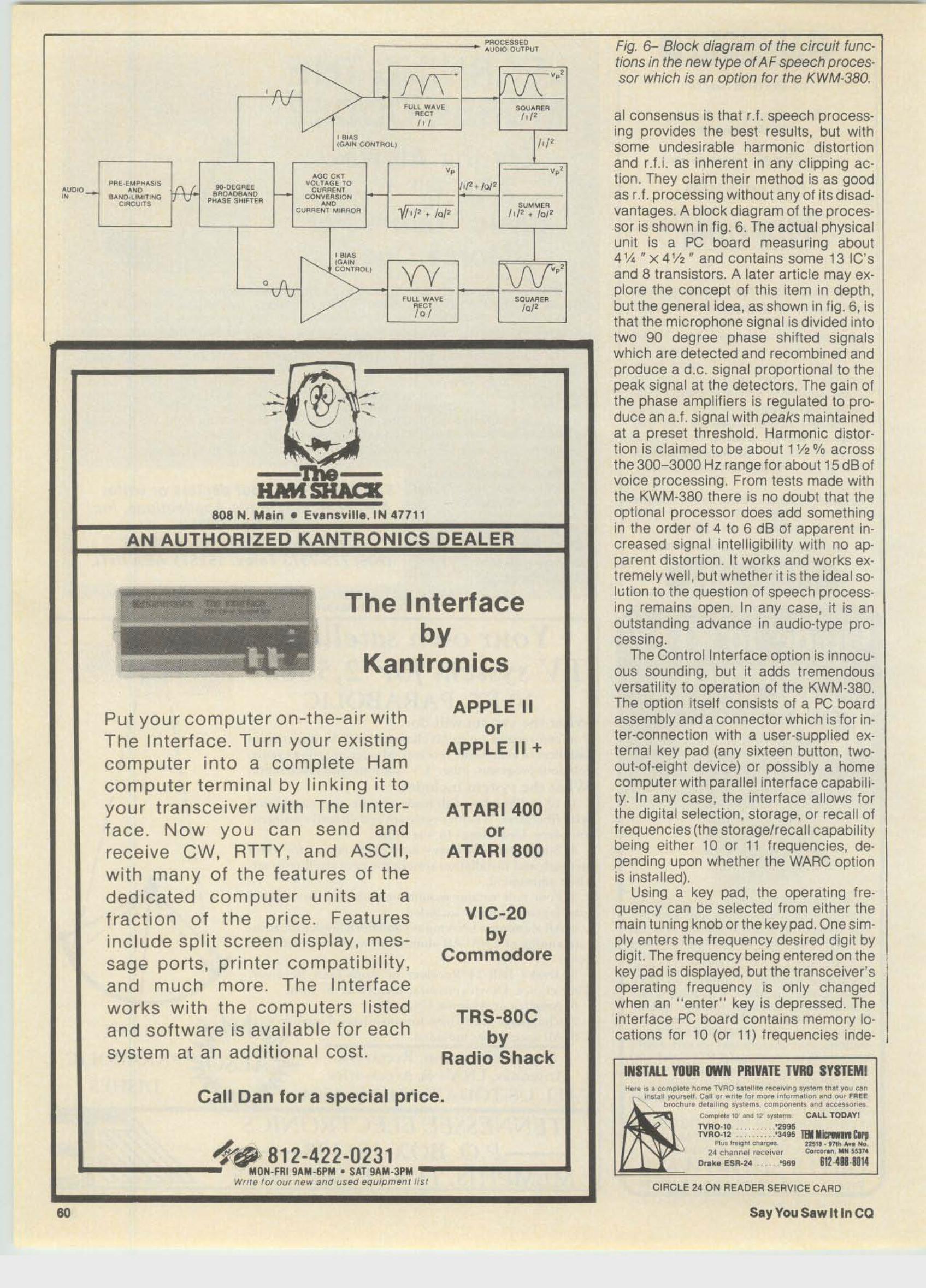
Fig. 6- Block diagram of the circuit functions in the new type of AF speech processor which is an option for the KWM-380.
INSTALL YOUR OWN PRIVATE TVJlO SYSTEMI
at consensus is that r.t. speech processing provides the best results, but withsome undesirable harmonic distortionand r.t.i. as inherent in any clipping action . They claim their method is as goodas r.f. processing without any of its disadvantages. A block diagram of the processor is shown in fig. 6. The actual physicalunit is a PC board measuring about41.4 "x 4 h • and contains some 13 IC'sand 8 transistors. A later article may explore the concept of this item in depth,but the general idea, as shown in fig. 6. isthat the microphone signal is divided intotwo 90 degree phase shifted signalswhich are detected and recombined andproduce a d.c. signal proportional to thepeak signal at the detectors. The gain ofthe phase amplifiers is regulated to ereduce an a.f . signal with peaks maintainedat a preset threshold. Harmonic distortion is claimed to be about 1Y2 % acrossthe 300-3000 Hz range for about 15dB ofvoice processing . From tests made withthe KWM-380 there is no doubt that theoptional processor does add somethingin the order of 4 to 6 dB of apparent increased signal intelligibility with no apparent distortion. It works and works extremely welt, but whether it is the idea l solution to the question of speech processing remains open. In any case, it is anoutstanding advance in audio-type processing .
The Control Interface option is innocuous sounding. but it adds tremendousversatility to operation of the KWM-380.The option itself consists of a PC boardassembly and a connector which is for ln.ter -connectlon with a user-supplied external key pad (any sixteen button, twoout-ot-erqbt device) or possibly a homecomputer with parallel interface capabi!ity. In any case, the interface allows forthe digital selection, storage, or recall offrequencies (the storage/recall capabilitybeing either 10 or 11 frequencies, depending upon whether the WARC optionis installed).
Using a key pad, the operating frequency can be selected from either themai n tuning knob or the keypad.One sfrnply enters the frequency desired digit bydigit. The frequency being entered on thekey pad is displayed, but the transceiver's I
operating frequency is only changedwhen an "enter " key is depressed. Theinterface PC board contains memory locations for 10 (or 11) frequencies inde-
/ ./,
s" .....,"1,12 • /0/'
PROC..SED'UOI0 00''''-''
APPLE IIor
APPLE II +
ATARI400or
ATARI800
VIC-20by
Commodore
TRS-80Cby
Radio Shack
FUll "'.V,.ECT101
VY
1N' • 10/'
The Interfaceby
Kantronics
, 8<• •,GAIN CON'~Ol. I
' 8 ....5,G~tN
CO~T"""-)
808 N. Mein • EV8nsvllle , IN 47711
••
•• ••
AN AUTHORIZED KANTRONICS DEALER
Put your computer on-the-air wi thThe Interface. T urn your existingcomputer into a comp lete Hamcompute r te rmi na l by linki ng it toyour transceiver with Th e Interface . Now you can send andreceive CW, RTTY, and ASC II,with many of the features of thededicated compute r un its at afraction of the price. Fea turesinc lude spl it screen display, message ports, printer compatibi li ty,and much more. T he Interfacewo rks w ith the compu ters listedand software is available for eachsystem at an additional cost.
.~
•
Call Dan lor a special price.
+~ 812-422-0231L. ~ MDN-FRlgAM-6PM • SAT 9AM-3PM --------wme for au' new an" used equ.pmf!nt IiSl
...... .. . com_. "0"" TliRO ••to"'" ,.".""no ,,,,tomIho' \'0" 00",,;n,to"10'''''" Col t '" ""'010' mo'. '"'0""""" . ""0"" FR••~ " ''''Cn"'' dO""''''l ...at.",.. oom"""o"" ."" .cco...,....
eom.o- ,.' _ 0> .......... CAL L TODAYI
lVRo-l0 , . , " " '2_lVRO-12 ':Wll!i lBIlirlwMCIr,..........'" , "'" ...... - ......-....
24 "...nM! 'OCO;'" Co<_" ,,," ..0<.~.ESR· 2' . .. '160 BU·4II·lt14
CIRCLE 24 ON READER SERVICE CARD
eo Say You Saw It In CQ

Table 1/- Transceive frequency coverages of the KWM-380 when the S8 10 WARe option ROM is installed.
$23.00
...$ 18.95 $3.05 $22 .00
$19.95 $3 .05u usem . ...c
Order botl'l books at the same time fOt'$41.95 Il'Ic l ud l l'lg sl'llpplng.
1983CALLBOOKS
SPECIAL DFFER!~ Amateur Radiol~I Emblem Patch.......1I .... - only $2.50 postpaid
...10 '.'''UR116 kca aa INC .
~ ::t~h~·;~·~ Orl ....Uke Bluff. IL 60044. USA
Th. la test .dltlons of the world·famousR.-dlo Amat.ur C:allbook w ill be a...allabl.soon . Th. U ,S, .dltlon f.a tures o ....r400,000 llst lngs. w ith o ....r 75.000 changesfrom last year. The For.lgn . d l tlol'l I'las o ....r370,000 listings, o ...er 50,000 chan!l8s. Eachb ook li st s calls and the address Informationyou nee c t o send QSL'5 . Spacia l f . al u r. sInclu de call ch anges. census of ama leu rlicenses, worte-wtae QS L b u reaus, p re flKesof the w orld , Internati onal postal rat es , , n dmuch more. The new 1 9 8 3 Call1)ooks willb. pub lished December 1, 1982. Order yourcooles now.
••
Order today!NEW 1983RADID AMATEUR CALLBDDKSREADY DECEMBER 1ST!
PtoIgasu s o n b lu e field, rec I.tterl n g. 3" w ideK 3" h i gh . G reat on Jack.ts and cap s,
O rder from your oeaier or directly fromthe PUbllsh.r. All direc t orders add sl'llpPlngCl'large . Forel9n resld.n ts ,dd $4 .55 forshiPPing. 1111"015 resld .nts add 5.. sales t,K.
wnh S8 10 (MHz)
No change3.25104.256.75107.55
10.10101 0.1513.751014.60
1B,060101 B.17020.75 1021.70
24.890 10 24,990No change
postcard reply form which will put thepurchaser on automatic distr ibution forall future service bulletins as long as theKWM-380 remains in production. Quite afew such service bulletins were issued upto January 1981, The last one containedin the manua l reviewed was dated August1981 and was only info rmation on WAReconversion.
Deale r and fac tory service for theKWM-380 is available and there is a oneyear warranty. Those restric ted to certain APO/FPO addresses. howeve r,might note that the KWM-380 is too large(with packing) for Parcel Post shipment,and freight shipment must be used.
The KWM-380 can be remotely controfled by a key pad such as the one shownhere (or a similar one supplied by theuser). A control interface cotton has to beinstalled in the KWM-380 to use the keypad, but then one will have key-pad control of frequenc y entry. storage, and reocall. If one imagines the key pad on theright of the trom-oenet view of theKWM-380 showing the microphone onthe left. one has a comoetetv integrated,
automated h.f. station.
SummaryThe KWM·380 is an outstanding piece
of equ ipment . It offers ex tremely sophisticated operating capabilities using stateot-the-arttechnoloqy. but without a frontpanel so c luttered with knobs, push buttons. and switches that one misses out onthe fun of operating whi le trying to figureout how to operate a tra nsceive r. It is notinexpensive. But, its design concept issound, and, as RockwellfCollins is willingto put in black and white, " No yearly model changes. As circuit improvements andmodifications are made to the KWM·380.its style does not become obsolete." II
14.0 10 14.35
28.0 to 29.7
2 1.001021.45
Without $B 10 (MHz)
1.BI02.03.5 10 4.07.010 7.3
Band (Mltlrs)
160BO40so201615t210
pendent of the two v.f .o. registers. Tostore any frequency, it is entered by key'board selection and addressed to a desired memory location (e.g. , 1,2,3, etc .).The transceive r can continue on its tun ing knob selected operating frequency, ifdesired, during the process. Or, the current operating frequency can be storedby a store and memory location key padcommand. Recalling a frequency consrsts ctpressing a recall key and a memory location. This action loads the storedfrequency into the v.t.o. reg ister in use (Aor B) and sets the transceiver's operatingfrequency to the reca lled frequency. Onecan also use key pad commands to manually step the transceiver through eachmemory star ting from the present memory location in use . Blank or cle ared memory locations are skipped during the manual stepping process.
The key pad frequency cont rol optionObviously adds all sorts of operating pessibillties to the KWM·380, ranging fromserious DX chasing across several bandsif desired (remember, the re is no bandswi tc h) to switching to a news programdu ring a boring net session. Removingpower from the transceiver will clea r allmemory locations .
Manual and Service NotesAn operati ng manua l does, of course,
come with the KWM-380, and it con tainsvery clear, practical information for getting the uni t into operation. It has a multitude of photos and illustrations all directed towards telling the operator hOw 10
hook up the transceiver, which controlsto turn for various functions, etc. It alsocontains a limited amount of informationon maintenance and some PC board interconnection data , so jf a PC board is exchanged. one can understand wh ich Interconnecting cables are involved.
A separate, outre elaborate servicemanual is ava ilable for about $40. Thismanual is extremely complete with thorough information on PC board layouts.schematic diagrams, alignment and testdata, etc. Complete parts data is givenalong wit h the name and address in theU.S. of the manufacturer of every component used (except common resistors, capacitors, hardware, etc .). The manualalso contains a complete set of servicebulletins issued for the KWM·380 and a
Say You Saw It In COCIRCLE 11. ON READER SERVICE CARD
63