Embed Size (px)
Citation preview
Rockwell Automation Library of Process Objects: Condition Gate Delay (P_Gate)Version 3.5
Reference Manual
IMPORTANT This manual applies to the Rockwell Automation Library of Process Objects version 3.5 or earlier.For Rockwell Automation Library of Process Objects version 4.0 or later, use the following manuals:• PROCES-RM013 contains logic instructions• PROCES-RM014 contains display elements
Important User Information
Read this document and the documents listed in the additional resources section about installation, configuration, and operation of this equipment before you install, configure, operate, or maintain this product. Users are required to familiarize themselves with installation and wiring instructions in addition to requirements of all applicable codes, laws, and standards.
Activities including installation, adjustments, putting into service, use, assembly, disassembly, and maintenance are required to be carried out by suitably trained personnel in accordance with applicable code of practice.
If this equipment is used in a manner not specified by the manufacturer, the protection provided by the equipment may be impaired.
In no event will Rockwell Automation, Inc. be responsible or liable for indirect or consequential damages resulting from the use or application of this equipment.
The examples and diagrams in this manual are included solely for illustrative purposes. Because of the many variables and requirements associated with any particular installation, Rockwell Automation, Inc. cannot assume responsibility or liability for actual use based on the examples and diagrams.
No patent liability is assumed by Rockwell Automation, Inc. with respect to use of information, circuits, equipment, or software described in this manual.
Reproduction of the contents of this manual, in whole or in part, without written permission of Rockwell Automation, Inc., is prohibited.
Throughout this manual, when necessary, we use notes to make you aware of safety considerations.
Labels may also be on or inside the equipment to provide specific precautions.
Allen-Bradley, Rockwell Software, Rockwell Automation, RSLogix, Logix5000, FactoryTalk, PlantPAx, and ControlLogix are trademarks of Rockwell Automation, Inc.
Trademarks not belonging to Rockwell Automation are property of their respective companies.
WARNING: Identifies information about practices or circumstances that can cause an explosion in a hazardous environment, which may lead to personal injury or death, property damage, or economic loss.
ATTENTION: Identifies information about practices or circumstances that can lead to personal injury or death, property damage, or economic loss. Attentions help you identify a hazard, avoid a hazard, and recognize the consequence.
IMPORTANT Identifies information that is critical for successful application and understanding of the product.
SHOCK HAZARD: Labels may be on or inside the equipment, for example, a drive or motor, to alert people that dangerous voltage may be present.
BURN HAZARD: Labels may be on or inside the equipment, for example, a drive or motor, to alert people that surfaces may reach dangerous temperatures.
ARC FLASH HAZARD: Labels may be on or inside the equipment, for example, a motor control center, to alert people to potential Arc Flash. Arc Flash will cause severe injury or death. Wear proper Personal Protective Equipment (PPE). Follow ALL Regulatory requirements for safe work practices and for Personal Protective Equipment (PPE).
Table of Contents
Preface Software Compatibility and Content Revision. . . . . . . . . . . . . . . . . . . . . . . 5Additional Resources . . . . . . . . . . . . . . . . . . . . . . . . . . . . . . . . . . . . . . . . . . . . . . 5
Condition Gate Delay (P_Gate) Guidelines . . . . . . . . . . . . . . . . . . . . . . . . . . . . . . . . . . . . . . . . . . . . . . . . . . . . . . . . 8Functional Description . . . . . . . . . . . . . . . . . . . . . . . . . . . . . . . . . . . . . . . . . . . . 8Required Files. . . . . . . . . . . . . . . . . . . . . . . . . . . . . . . . . . . . . . . . . . . . . . . . . . . . . 8
Controller File . . . . . . . . . . . . . . . . . . . . . . . . . . . . . . . . . . . . . . . . . . . . . . . . 8Visualization Files . . . . . . . . . . . . . . . . . . . . . . . . . . . . . . . . . . . . . . . . . . . . . 9
Controller Code . . . . . . . . . . . . . . . . . . . . . . . . . . . . . . . . . . . . . . . . . . . . . . . . . 10Condition Gate Delay Input Structure . . . . . . . . . . . . . . . . . . . . . . . . . 10Condition Gate Delay Output Structure . . . . . . . . . . . . . . . . . . . . . . . 11Condition Gate Delay Local Configuration Tags. . . . . . . . . . . . . . . . 11
Operations . . . . . . . . . . . . . . . . . . . . . . . . . . . . . . . . . . . . . . . . . . . . . . . . . . . . . . 12Modes . . . . . . . . . . . . . . . . . . . . . . . . . . . . . . . . . . . . . . . . . . . . . . . . . . . . . . . 12Alarms. . . . . . . . . . . . . . . . . . . . . . . . . . . . . . . . . . . . . . . . . . . . . . . . . . . . . . . 12Simulation . . . . . . . . . . . . . . . . . . . . . . . . . . . . . . . . . . . . . . . . . . . . . . . . . . . 12Execution . . . . . . . . . . . . . . . . . . . . . . . . . . . . . . . . . . . . . . . . . . . . . . . . . . . . 12Implementation by Using the EnableIn False Feature . . . . . . . . . . . . 13
Display Elements . . . . . . . . . . . . . . . . . . . . . . . . . . . . . . . . . . . . . . . . . . . . . . . . . 15Faceplate . . . . . . . . . . . . . . . . . . . . . . . . . . . . . . . . . . . . . . . . . . . . . . . . . . . . . . . . 15
Operator Tab . . . . . . . . . . . . . . . . . . . . . . . . . . . . . . . . . . . . . . . . . . . . . . . . 16
Rockwell Automation Publication SYSLIB-RM041C-EN-P - January 2016 3

Table of Contents
Notes:
4 Rockwell Automation Publication SYSLIB-RM041C-EN-P - January 2016
Preface
This manual contains new and updated information. Changes throughout this revision are marked by change bars, as shown to the right of this paragraph.
Software Compatibility and Content Revision
For the latest compatible software information and to download the Rockwell Automation® Library of Process Objects, see the Product Compatibility and Download Center at http://www.rockwellautomation.com/rockwellautomation/support/pcdc.page.
For general library considerations, see Rockwell Automation Library of Process Objects, publication PROCES-RM002.
Additional Resources These documents contain additional information concerning related products from Rockwell Automation.
You can view or download publications athttp:/www.rockwellautomation.com/literature/. To order paper copies of technical documentation, contact your local Allen-Bradley® distributor or Rockwell Automation sales representative.
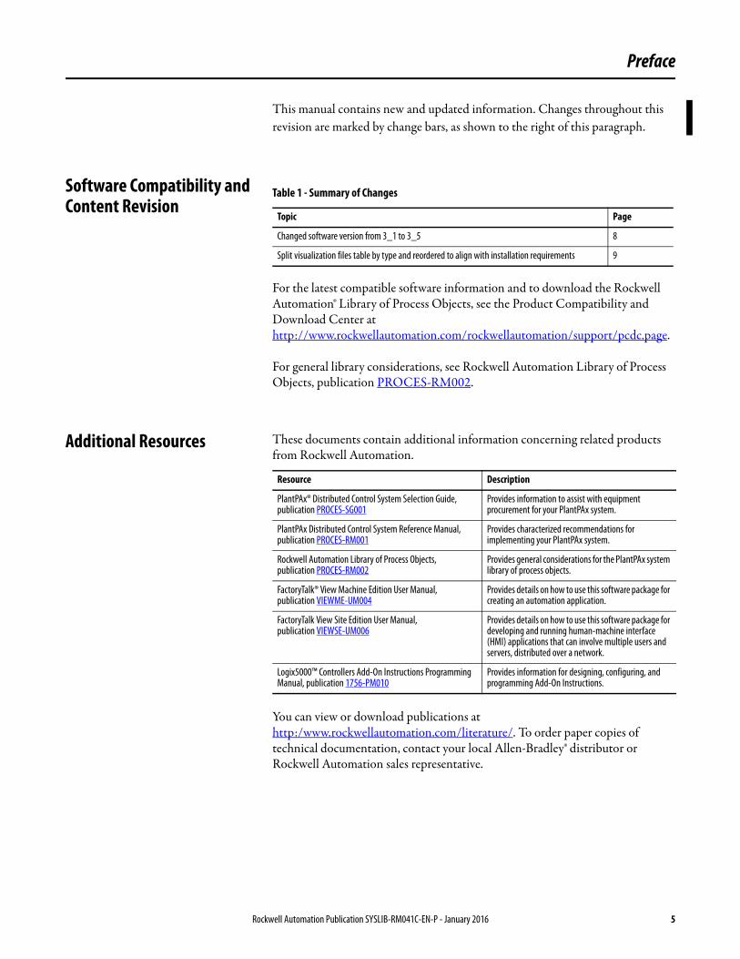
Table 1 - Summary of Changes
Topic Page
Changed software version from 3_1 to 3_5 8
Split visualization files table by type and reordered to align with installation requirements 9
Resource Description
PlantPAx® Distributed Control System Selection Guide, publication PROCES-SG001
Provides information to assist with equipment procurement for your PlantPAx system.
PlantPAx Distributed Control System Reference Manual, publication PROCES-RM001
Provides characterized recommendations for implementing your PlantPAx system.
Rockwell Automation Library of Process Objects,publication PROCES-RM002
Provides general considerations for the PlantPAx system library of process objects.
FactoryTalk® View Machine Edition User Manual,publication VIEWME-UM004
Provides details on how to use this software package for creating an automation application.
FactoryTalk View Site Edition User Manual,publication VIEWSE-UM006
Provides details on how to use this software package for developing and running human-machine interface (HMI) applications that can involve multiple users and servers, distributed over a network.
Logix5000™ Controllers Add-On Instructions Programming Manual, publication 1756-PM010
Provides information for designing, configuring, and programming Add-On Instructions.
Rockwell Automation Publication SYSLIB-RM041C-EN-P - January 2016 5

Preface
Notes:
6 Rockwell Automation Publication SYSLIB-RM041C-EN-P - January 2016
Condition Gate Delay (P_Gate)
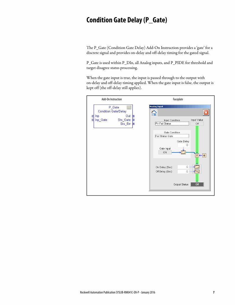
The P_Gate (Condition Gate Delay) Add-On Instruction provides a ‘gate’ for a discrete signal and provides on-delay and off-delay timing for the gated signal.
P_Gate is used within P_DIn, all Analog inputs, and P_PIDE for threshold and target disagree status processing.
When the gate input is true, the input is passed through to the output with on-delay and off-delay timing applied. When the gate input is false, the output is kept off (the off-delay still applies).
Add-On Instruction Faceplate
Rockwell Automation Publication SYSLIB-RM041C-EN-P - January 2016 7
Condition Gate Delay (P_Gate)
Guidelines This instruction is integrated with the following Rockwell Automation Library Objects:
• Basic Analog Input (P_AIn)• Advanced Analog Input (P_AInAdv)• Dual Sensor Analog Input (P_AInDual)• Multiple Analog Input (P_AInMulti)• Discrete Input Object (P_DIn)• Enhanced PID (P_PIDE)
Functional Description The primary operations of the P_Gate Add-On Instruction and its faceplate are: • Provides gate input to turn on and off input monitoring• Provides Gate delay to define the time the gate input must be on for status
outputs to be enabled• Provides on and off delays for the status output• Provides configurable strings for gate and status condition descriptions• Provides faceplate for setup of gate delay, on delay, off delay, and strings
Required Files Add-On Instructions are reusable code objects that contain encapsulated logic that can streamline implementing your system. This lets you create your own instruction set for programming logic as a supplement to the instruction set provided natively in the ControlLogix® firmware. An Add-On Instruction is defined once in each controller project, and can be instantiated multiple times in your application code as needed.
Controller File
The P_Gate_3_5-00_AOI.L5X Add-On Instruction must be imported into the controller project to be used in the controller configuration. The service release number (boldfaced) can change as service revisions are created.
8 Rockwell Automation Publication SYSLIB-RM041C-EN-P - January 2016
Condition Gate Delay (P_Gate)
Visualization Files
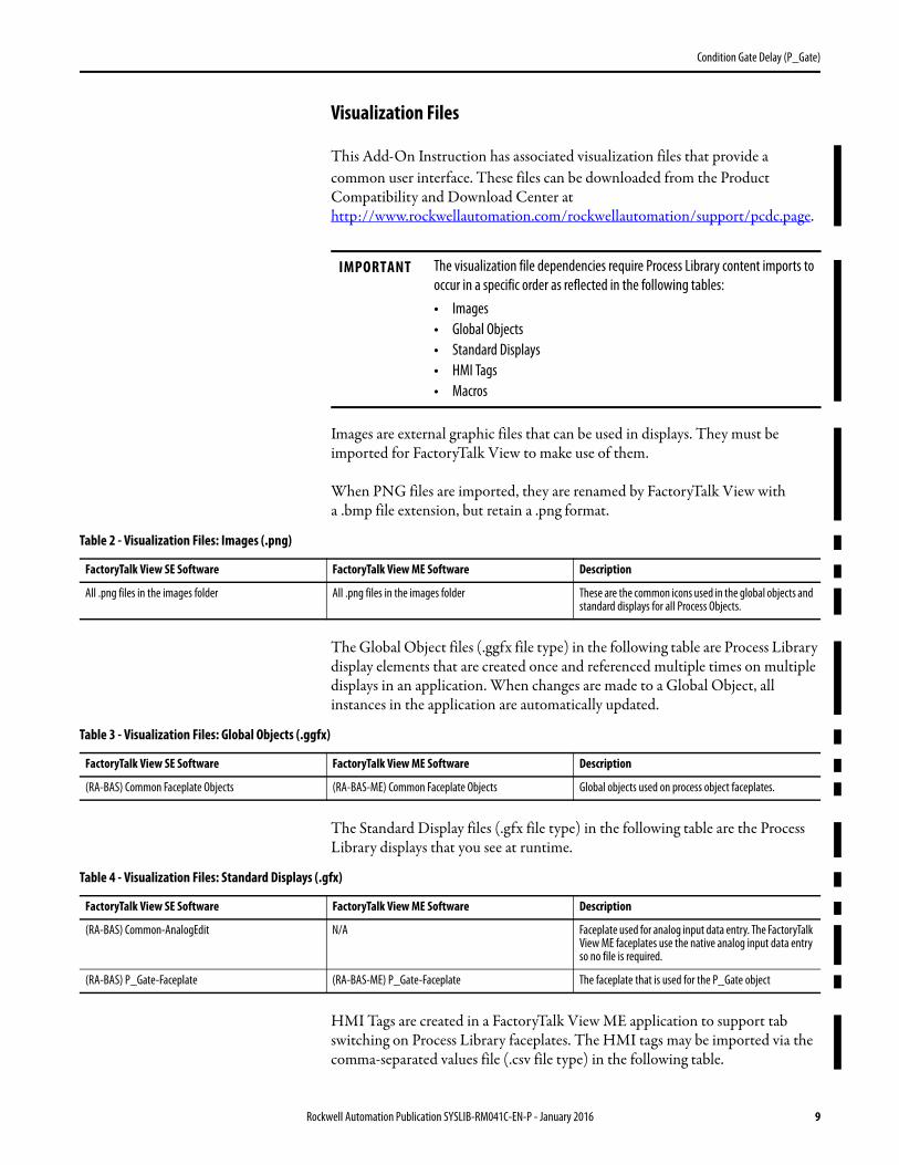
This Add-On Instruction has associated visualization files that provide a common user interface. These files can be downloaded from the Product Compatibility and Download Center at http://www.rockwellautomation.com/rockwellautomation/support/pcdc.page.
Images are external graphic files that can be used in displays. They must be imported for FactoryTalk View to make use of them.
When PNG files are imported, they are renamed by FactoryTalk View with a .bmp file extension, but retain a .png format.
The Global Object files (.ggfx file type) in the following table are Process Library display elements that are created once and referenced multiple times on multiple displays in an application. When changes are made to a Global Object, all instances in the application are automatically updated.
The Standard Display files (.gfx file type) in the following table are the Process Library displays that you see at runtime.
HMI Tags are created in a FactoryTalk View ME application to support tab switching on Process Library faceplates. The HMI tags may be imported via the comma-separated values file (.csv file type) in the following table.
IMPORTANT The visualization file dependencies require Process Library content imports to occur in a specific order as reflected in the following tables:• Images• Global Objects• Standard Displays• HMI Tags• Macros
Table 2 - Visualization Files: Images (.png)
FactoryTalk View SE Software FactoryTalk View ME Software Description
All .png files in the images folder All .png files in the images folder These are the common icons used in the global objects and standard displays for all Process Objects.
Table 3 - Visualization Files: Global Objects (.ggfx)
FactoryTalk View SE Software FactoryTalk View ME Software Description
(RA-BAS) Common Faceplate Objects (RA-BAS-ME) Common Faceplate Objects Global objects used on process object faceplates.
Table 4 - Visualization Files: Standard Displays (.gfx)
FactoryTalk View SE Software FactoryTalk View ME Software Description
(RA-BAS) Common-AnalogEdit N/A Faceplate used for analog input data entry. The FactoryTalk View ME faceplates use the native analog input data entry so no file is required.
(RA-BAS) P_Gate-Faceplate (RA-BAS-ME) P_Gate-Faceplate The faceplate that is used for the P_Gate object
Rockwell Automation Publication SYSLIB-RM041C-EN-P - January 2016 9
Condition Gate Delay (P_Gate)
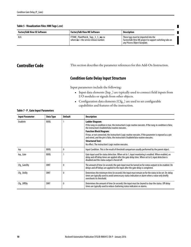
Controller Code This section describes the parameter references for this Add-On Instruction.
Condition Gate Delay Input Structure
Input parameters include the following:• Input data elements (Inp_) are typically used to connect field inputs from
I/O modules or signals from other objects.• Configuration data elements (Cfg_) are used to set configurable
capabilities and features of the instruction.
Table 5 - Visualization Files: HMI Tags (.csv)
FactoryTalk View SE Software FactoryTalk View ME Software Description
N/A FTVME_PlantPAxLib_Tags_3_5_xx.csvwhere xx = the service release number.
These tags must be imported into theFactoryTalk View ME project to support switching tabs on any Process Object faceplate.
Table 7 - P_Gate Input Parameters
Input Parameter Data Type Default Description
EnableIn BOOL 1 Ladder Diagram:If the rung-in condition is true, the instruction’s Logic routine executes. If the rung-in condition is false, the instruction’s EnableInFalse routine executes.Function Block Diagram:If true, or not connected, the instruction’s Logic routine executes. If the parameter is exposed as a pin and wired, and the pin is false, the instruction’s EnableInFalse routine executes.Structured Text:No effect. The instruction’s Logic routine executes.
Inp BOOL 0 Input Condition. This is the result of threshold comparison usually performed by the parent object.
Inp_Gate BOOL 1 Gate input used for status detection. When set to 1, input monitoring is enabled. When enabled, on delay and off delay times are applied after the gate delay time. When set to 0, input detection is disabled and the status output is forced off.
Cfg_GateDly DINT 0 The amount of time (in seconds) the gate input must be turned on for status outputs to be enabled. On delays and off delays are applied to the input after the gate delay is completed.
Cfg_OnDly DINT 0 Determines the minimum time (in seconds) the input must remain on for the status to be set. On-delay times are typically used to avoid unnecessary status indication or alarm when a value only briefly overshoots its threshold.
Cfg_OffDly DINT 0 Determines the amount of time (in seconds) the input must be cleared to clear the status. Off delay times are typically used to reduce chattering status indicators or alarms.
10 Rockwell Automation Publication SYSLIB-RM041C-EN-P - January 2016
Condition Gate Delay (P_Gate)
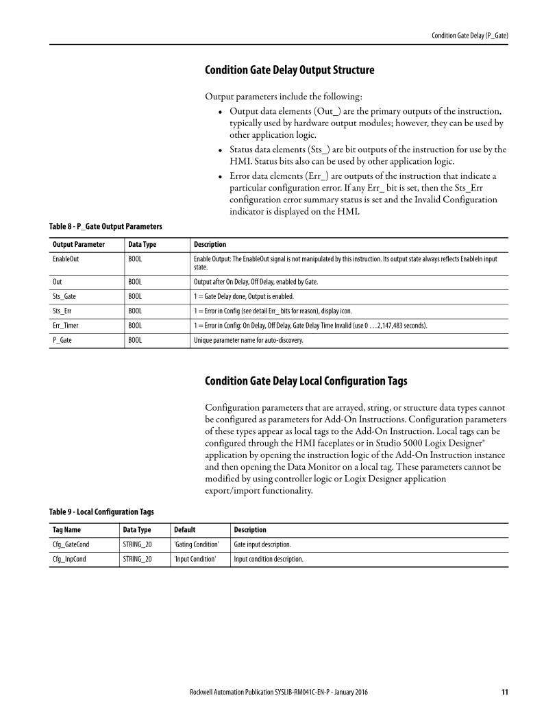
Condition Gate Delay Output Structure
Output parameters include the following:• Output data elements (Out_) are the primary outputs of the instruction,
typically used by hardware output modules; however, they can be used by other application logic.
• Status data elements (Sts_) are bit outputs of the instruction for use by the HMI. Status bits also can be used by other application logic.
• Error data elements (Err_) are outputs of the instruction that indicate a particular configuration error. If any Err_ bit is set, then the Sts_Err configuration error summary status is set and the Invalid Configuration indicator is displayed on the HMI.
Condition Gate Delay Local Configuration Tags
Configuration parameters that are arrayed, string, or structure data types cannot be configured as parameters for Add-On Instructions. Configuration parameters of these types appear as local tags to the Add-On Instruction. Local tags can be configured through the HMI faceplates or in Studio 5000 Logix Designer® application by opening the instruction logic of the Add-On Instruction instance and then opening the Data Monitor on a local tag. These parameters cannot be modified by using controller logic or Logix Designer application export/import functionality.
Table 8 - P_Gate Output Parameters
Output Parameter Data Type Description
EnableOut BOOL Enable Output: The EnableOut signal is not manipulated by this instruction. Its output state always reflects EnableIn input state.
Out BOOL Output after On Delay, Off Delay, enabled by Gate.
Sts_Gate BOOL 1 = Gate Delay done, Output is enabled.
Sts_Err BOOL 1 = Error in Config (see detail Err_ bits for reason), display icon.
Err_Timer BOOL 1 = Error in Config: On Delay, Off Delay, Gate Delay Time Invalid (use 0 …2,147,483 seconds).
P_Gate BOOL Unique parameter name for auto-discovery.
Table 9 - Local Configuration Tags
Tag Name Data Type Default Description
Cfg_GateCond STRING_20 'Gating Condition' Gate input description.
Cfg_InpCond STRING_20 'Input Condition' Input condition description.
Rockwell Automation Publication SYSLIB-RM041C-EN-P - January 2016 11
Condition Gate Delay (P_Gate)
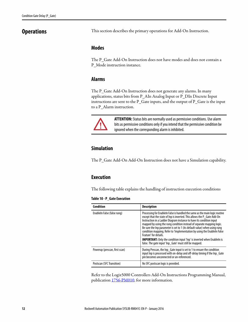
Operations This section describes the primary operations for Add-On Instruction.
Modes
The P_Gate Add-On Instruction does not have modes and does not contain a P_Mode instruction instance.
Alarms
The P_Gate Add-On Instruction does not generate any alarms. In many applications, status bits from P_AIn Analog Input or P_DIn Discrete Input instructions are sent to the P_Gate inputs, and the output of P_Gate is the input to a P_Alarm instruction.
Simulation
The P_Gate Add-On Add-On Instruction does not have a Simulation capability.
Execution
The following table explains the handling of instruction execution conditions
Refer to the Logix5000 Controllers Add-On Instructions Programming Manual, publication 1756-PM010, for more information.
ATTENTION: Status bits are normally used as permissive conditions. Use alarm bits as permissive conditions only if you intend that the permissive condition be ignored when the corresponding alarm is inhibited.
Table 10 - P_Gate Execution
Condition Description
EnableIn False (false rung) Processing for EnableIn False is handled the same as the main logic routine except that the state of Inp is inverted. This allows the P_Gate Add-On Instruction in a Ladder Diagram instance to have its condition input mapped by using the rung condition instead of separate mapping logic. Be sure the Inp parameter is set to 1 (its default value) when using rung condition mapping. Refer to ‘Implementation by using the EnableIn False Feature’ for details. IMPORTANT: Only the condition input ‘Inp’ is inverted when EnableIn is false. The gate input ‘Inp_Gate’ must still be mapped.
Powerup (prescan, first scan) During Prescan, the Inp_Gate input is set to 1 to ensure the condition input Inp is processed with on-delay and off-delay timing if the Inp_Gate pin becomes unconnected or un-referenced.
Postscan (SFC Transition) No SFC postscan logic is provided.
12 Rockwell Automation Publication SYSLIB-RM041C-EN-P - January 2016
Condition Gate Delay (P_Gate)
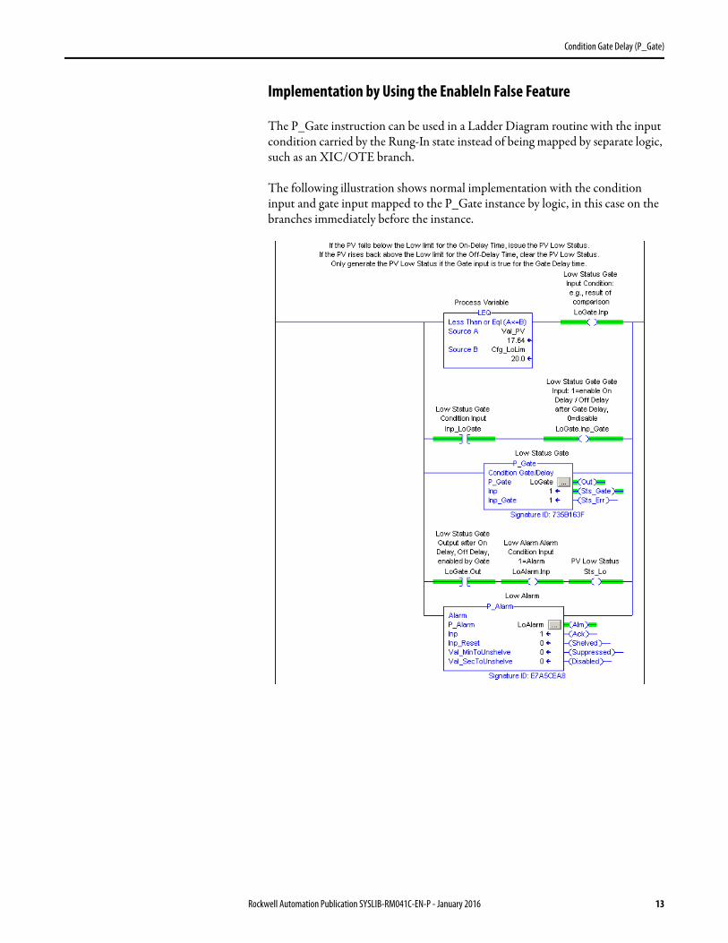
Implementation by Using the EnableIn False Feature
The P_Gate instruction can be used in a Ladder Diagram routine with the input condition carried by the Rung-In state instead of being mapped by separate logic, such as an XIC/OTE branch.
The following illustration shows normal implementation with the condition input and gate input mapped to the P_Gate instance by logic, in this case on the branches immediately before the instance.
Rockwell Automation Publication SYSLIB-RM041C-EN-P - January 2016 13
Condition Gate Delay (P_Gate)
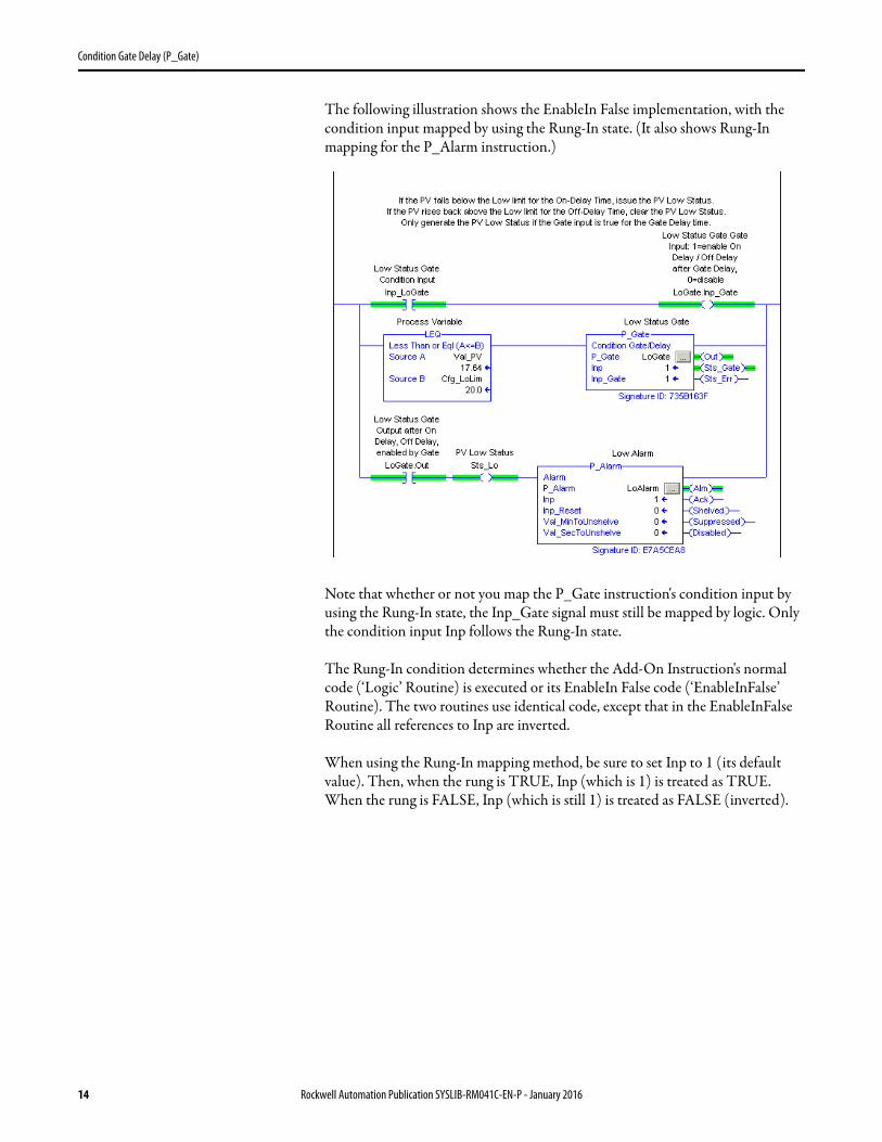
The following illustration shows the EnableIn False implementation, with the condition input mapped by using the Rung-In state. (It also shows Rung-In mapping for the P_Alarm instruction.)
Note that whether or not you map the P_Gate instruction's condition input by using the Rung-In state, the Inp_Gate signal must still be mapped by logic. Only the condition input Inp follows the Rung-In state.
The Rung-In condition determines whether the Add-On Instruction's normal code (‘Logic’ Routine) is executed or its EnableIn False code (‘EnableInFalse’ Routine). The two routines use identical code, except that in the EnableInFalse Routine all references to Inp are inverted.
When using the Rung-In mapping method, be sure to set Inp to 1 (its default value). Then, when the rung is TRUE, Inp (which is 1) is treated as TRUE. When the rung is FALSE, Inp (which is still 1) is treated as FALSE (inverted).
14 Rockwell Automation Publication SYSLIB-RM041C-EN-P - January 2016
Condition Gate Delay (P_Gate)
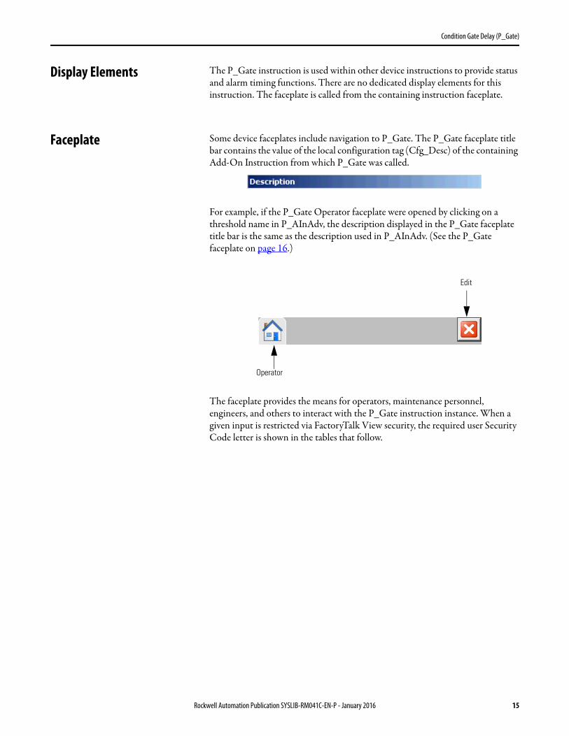
Display Elements The P_Gate instruction is used within other device instructions to provide status and alarm timing functions. There are no dedicated display elements for this instruction. The faceplate is called from the containing instruction faceplate.
Faceplate Some device faceplates include navigation to P_Gate. The P_Gate faceplate title bar contains the value of the local configuration tag (Cfg_Desc) of the containing Add-On Instruction from which P_Gate was called.
For example, if the P_Gate Operator faceplate were opened by clicking on a threshold name in P_AInAdv, the description displayed in the P_Gate faceplate title bar is the same as the description used in P_AInAdv. (See the P_Gate faceplate on page 16.)
The faceplate provides the means for operators, maintenance personnel, engineers, and others to interact with the P_Gate instruction instance. When a given input is restricted via FactoryTalk View security, the required user Security Code letter is shown in the tables that follow.
Operator
Edit
Rockwell Automation Publication SYSLIB-RM041C-EN-P - January 2016 15
Condition Gate Delay (P_Gate)
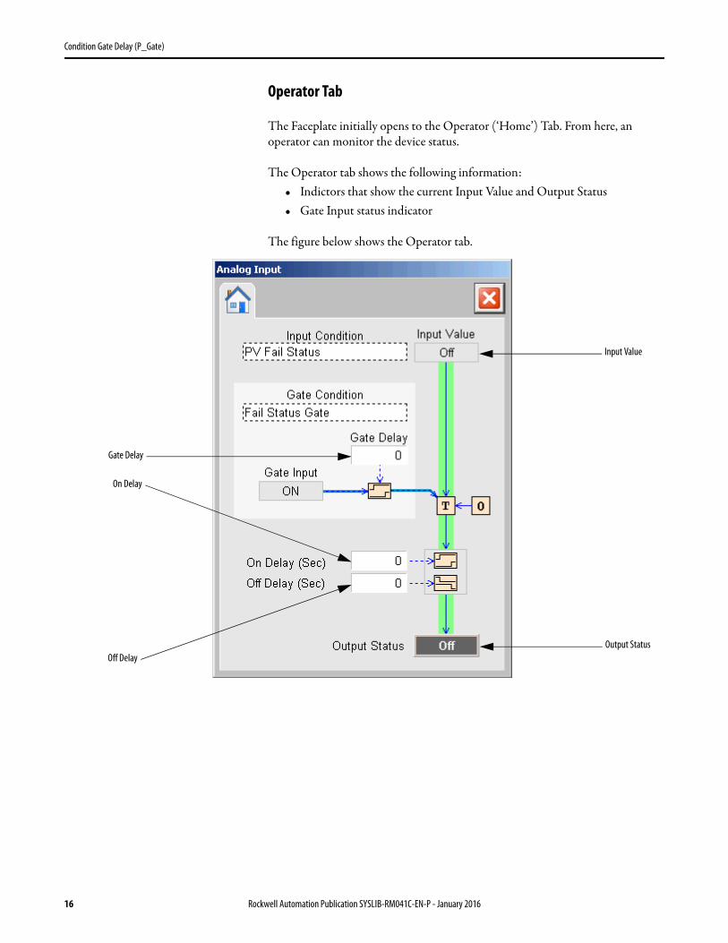
Operator Tab
The Faceplate initially opens to the Operator (‘Home’) Tab. From here, an operator can monitor the device status.
The Operator tab shows the following information:• Indictors that show the current Input Value and Output Status• Gate Input status indicator
The figure below shows the Operator tab.
Gate Delay
Input Value
On Delay
Off DelayOutput Status
16 Rockwell Automation Publication SYSLIB-RM041C-EN-P - January 2016
Condition Gate Delay (P_Gate)
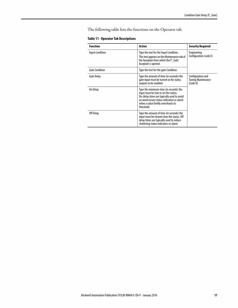
The following table lists the functions on the Operator tab.
Table 11 - Operator Tab Descriptions
Function Action Security Required
Input Condition Type the text for the Input Condition.This text appears on the Maintenance tab of the faceplate from which the P_Gate faceplate is opened.
Engineering Configuration (code E)
Gate Condition Type the text for the gate Condition.
Gate Delay Type the amount of time (in seconds) the gate input must be turned on for status outputs to be enabled.
Configuration and Tuning Maintenance (Code D)
On Delay Type the minimum time (in seconds) the input must be true to set the status. On-delay times are typically used to avoid an unnecessary status indication or alarm when a value briefly overshoots its threshold.
Off Delay Type the amount of time (in seconds) the input must be cleared clear the status. Off delay times are typically used to reduce chattering status indicators or alarm.
Rockwell Automation Publication SYSLIB-RM041C-EN-P - January 2016 17

Condition Gate Delay (P_Gate)
Notes:
18 Rockwell Automation Publication SYSLIB-RM041C-EN-P - January 2016

Publication SYSLIB-RM041C-EN-P - January 2016Supersedes Publication SYSLIB-RM041B-EN-P - August 2014 Copyright © 2016 Rockwell Automation, Inc. All rights reserved. Printed in the U.S.A.
Rockwell Automation Support
Rockwell Automation provides technical information on the Web to assist you in using its products.At http://www.rockwellautomation.com/support you can find technical and application notes, sample code, and links to software service packs. You can also visit our Support Center at https://rockwellautomation.custhelp.com/ for software updates, support chats and forums, technical information, FAQs, and to sign up for product notification updates.
In addition, we offer multiple support programs for installation, configuration, and troubleshooting. For more information, contact your local distributor or Rockwell Automation representative, or visithttp://www.rockwellautomation.com/services/online-phone.
Installation Assistance
If you experience a problem within the first 24 hours of installation, review the information that is contained in this manual. You can contact Customer Support for initial help in getting your product up and running.
New Product Satisfaction Return
Rockwell Automation tests all of its products to help ensure that they are fully operational when shipped from the manufacturing facility. However, if your product is not functioning and needs to be returned, follow these procedures.
Documentation Feedback
Your comments will help us serve your documentation needs better. If you have any suggestions on how to improve this document, complete this form, publication RA-DU002, available at http://www.rockwellautomation.com/literature/.
United States or Canada 1.440.646.3434
Outside United States or Canada Use the Worldwide Locator at http://www.rockwellautomation.com/rockwellautomation/support/overview.page, or contact your local Rockwell Automation representative.
United States Contact your distributor. You must provide a Customer Support case number (call the phone number above to obtain one) to your distributor to complete the return process.
Outside United States Please contact your local Rockwell Automation representative for the return procedure.
Rockwell Otomasyon Ticaret A.Ş., Kar Plaza İş Merkezi E Blok Kat:6 34752 İçerenköy, İstanbul, Tel: +90 (216) 5698400
Rockwell Automation maintains current product environmental information on its website athttp://www.rockwellautomation.com/rockwellautomation/about-us/sustainability-ethics/product-environmental-compliance.page.