Embed Size (px)
Citation preview
Proceedings of the 25th UKACM Conference on Computational Mechanics12 - 13 April 2017, University of Birmingham
Birmingham, United Kingdom
ROCKING OF SINGLE AND DUAL RIGID-BLOCK SYSTEMSSUBJECT TO GROUND EXCITATION: EXPERIMENTAL AND
COMPUTATIONAL ANALYSIS OF OVERTURNING CONDITIONS
Gordan Jelenić∗, Nina Čeh and Nenad Bićanić†
Faculty of Civil Engineering, University of Rijeka, R. Matejčić 3, 51 000 Rijeka, Republic of Croatia†Deceased
ABSTRACT
A prismatic block is analysed for overturning when subject to a constant ground acceleration of prescribedmagnitude and duration. The analytical overturning condition and a special numerical procedure are developedand assessed against experiments. Generalisation of the approach to rocking of a dual-block stack is outlined.
Key Words: rocking; rigid block; constant ground acceleration; overturning
1. IntroductionThe esteemed member of the United Kingdom Association of Computational Mechanics, and EmeritusProfessor at University of Glasgow, Nenad Bićanić, joined the Engineering Mechanics research groupat the Faculty of Civil Enineering of University of Rijeka in his native Republic of Croatia upon hisretirement from Glasgow in autumn 2010. Following his life-long interests in earthquake engineeringand computational dynamics and recognising the need to characterise in more detail dynamic sensitivityof discontinuous systems, from dry walls in ancient and traditional construction to thermal insulation ofgraphite cores in nuclear power-plant reactors, he set up an experimental dynamics laboratory and starteda number of new and exciting research topics in experimental and computational dynamics. Followinghis untimely demise in October 2016, we present to the Association a part of the research its valuedmember led so enthusiastically, related to rocking of blocky structures subject to ground motion.For this occasion, we investigate the conditions under which a single slender prismatic rigid blockoverturns under influence of constant-acceleration ground motion of various duration analytically, nu-merically and experimentally. A closed-form solution clearly separating the regions of pure translation,stable rocking, and overturning, is derived. A non-linear numerical time-stepping scheme specificallydesigned to detect the precise time of contact and preserve the angular momentum balance at the time ofcontact is also presented and its accuracy assessed against the analytical solution. An experimental testrig is described next involving the set-up designed to eliminate slipping and prescribe various magnitudesof constant acceleration and their duration, and used to validate the analytical and numerical results.The method may be generalised to the dual-block stack, where a situation in which the ground is setin motion by an impulse through a relatively short time period, left in uniform motion during whichthe system rocks in a stable fashion, and then subjected to a counter-impulse, is of critical importance.Such acceleration history often makes the upper block overturn and was a subject of Nenad’s specialinterest, and we conclude this contribution by presenting a test-rig designed by Nenad himself, capableof performing such a counter-impulse in a controlled manner.
2. Single block: analytical, numerical and experimental analysisA rigid prismatic block of mass m, a rectangular base of unit thickness, width b and height h (or thehalf-diagonal R of its frontal side and the angle of slenderness α = tan−1 b
h ) lies on a rigid groundplatform subject to a constant acceleration a0 during the prescribed time-segment t ∈ [0, ta] which drops
to zero for t > ta. We address the case whereby sliding between the block and the ground is preventedand investigate whether for a prescribed set of input parameters R, α, a0, ta the block will translate withthe ground, rock in a stable fashion or overturn. It is assumed that contact between the block and theground is maintained throughout the motion.For a relatively small a0, the block moves along with the ground without rocking. The block shall tiltaround one of its corners when the moment of its weight with respect to that corner becomes equal toan infinitesimal time change of the corresponding angular momentum. In particular, for a0 > g tanα theblock ceases to move translationally and starts rotating by θ around one of its corners according to
Üθ + p2[sin(α − θ) − a cos(α − θ)/g] = 0, (1)
where p = 12
√3gR is the so-called frequency parameter. For small α and θ, this equation becomes linear
with a constant coefficient of the form Üθ−p2θ = p2 (a/g − α), having the solution θ = ( a0g −α)(cosh pt−1)
for t ≤ ta and θ = α(1 − cosh pt) + a0g [(1 − cosh pta) cosh pt + sinh pta sinh pt] for t > ta. The least
critical situation in which the block will overturn takes place when θ = α and Ûθ > 0 (i.e. when θ > α)for t > ta. This gives the following condition for overturning
α − a0g (1 − cosh pta)a0g sinh pta
< tanh pt ≤ 1 =⇒ pta > − lna0αg − 1
a0αg
. (2)
The problem may be also analysed numerically. The motion is described via
Üθ + p2[sin(α − θ) − a cos(α − θ)/g] = 0, θ ≥ 0Üθ − p2[sin(α − θ) + a cos(α − θ)/g] = 0, θ ≤ 0. (3)
These equationswill be numerically solved usingNewmark’s trapezoidal time-stepping rule [1] at discretetime instants separated by a time step ∆t, along with the Newton–Raphson iterative solution procedure.To make the transition from one of the equations of motion to the other without any constraint violation itbecomes important to detect the time of contact precisely. We propose a technique in which the rotationat the end of a time step is monitored throughout the analysis for the change of sign. When such change isdetected, say at a time tn+1, dynamic equilibrium over the time step is repeated for an unknown time-steplength ∆t ′ under the condition that θn+1 := 0. After the impact, the original time-step length is restoredand the time-stepping procedure switches to the other equation of motion.When the exact time of the impact is detected, angular velocity Ûθ+ at the start of the first post-impactstep needs to be reduced with respect to that at the end of the last pre-impact step ( Ûθ−) following theangular-momentum balance via Ûθ+ =
(1 − 1.5 sin2 α
)Ûθ− [2], while angular acceleration Üθ+ follows from
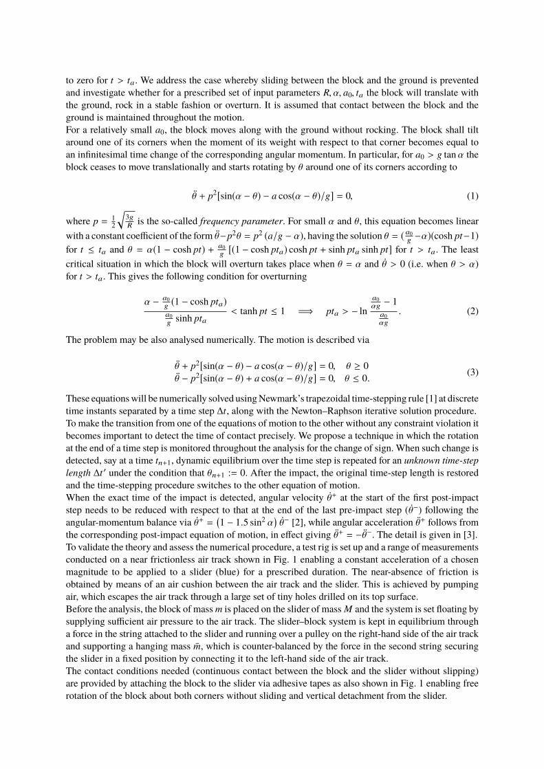
the corresponding post-impact equation of motion, in effect giving Üθ+ = − Üθ−. The detail is given in [3].To validate the theory and assess the numerical procedure, a test rig is set up and a range of measurementsconducted on a near frictionless air track shown in Fig. 1 enabling a constant acceleration of a chosenmagnitude to be applied to a slider (blue) for a prescribed duration. The near-absence of friction isobtained by means of an air cushion between the air track and the slider. This is achieved by pumpingair, which escapes the air track through a large set of tiny holes drilled on its top surface.Before the analysis, the block of mass m is placed on the slider of mass M and the system is set floating bysupplying sufficient air pressure to the air track. The slider–block system is kept in equilibrium througha force in the string attached to the slider and running over a pulley on the right-hand side of the air trackand supporting a hanging mass m̄, which is counter-balanced by the force in the second string securingthe slider in a fixed position by connecting it to the left-hand side of the air track.The contact conditions needed (continuous contact between the block and the slider without slipping)are provided by attaching the block to the slider via adhesive tapes as also shown in Fig. 1 enabling freerotation of the block about both corners without sliding and vertical detachment from the slider.
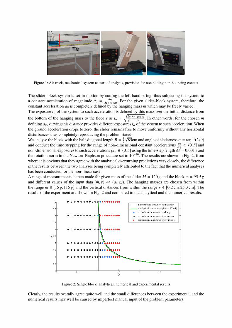
Figure 1: Air-track, mechanical system at start of analysis, provision for non-sliding non-bouncing contact
The slider–block system is set in motion by cutting the left-hand string, thus subjecting the system toa constant acceleration of magnitude a0 =
m̄gM+m+m̄ . For the given slider–block system, therefore, the
constant acceleration a0 is completely defined by the hanging mass m̄ which may be freely varied.The exposure ta of the system to such acceleration is defined by this mass and the initial distance fromthe bottom of the hanging mass to the floor y as ta =
√2yg
M+m+m̄m̄ . In other words, for the chosen m̄
defining a0, varying this distance provides different exposures ta of the system to such acceleration.Whenthe ground acceleration drops to zero, the slider remains free to move uniformly without any horizontaldisturbances thus completely reproducing the problem stated.We analyse the block with the half-diagonal length R = 1
2√
85cm and angle of slederness α ≡ tan−1(2/9)and conduct the time stepping for the range of non-dimensional constant accelerations a0
αg ∈ 〈0, 3] andnon-dimensional exposures to such accelerations pta ∈ 〈0, 5] using the time-step length∆t = 0.001 s andthe rotation norm in the Newton–Raphson procedure set to 10−10. The results are shown in Fig. 2, fromwhere it is obvious that they agree with the analytical overturning predictions very closely, the differencein the results between the two analyses being completely attributed to the fact that the numerical analyseshas been conducted for the non-linear case.A range of measurements is then made for given mass of the slider M = 120 g and the block m = 95.5 gand different values of the input data (m̄, y) ⇔ (a0, ta). The hanging masses are chosen from withinthe range m̄ ∈ [15 g, 115 g] and the vertical distances from within the range y ∈ [0.2 cm, 25.3 cm]. Theresults of the experiment are shown in Fig. 2 and compared to the analytical and the numerical results.
Figure 2: Single block: analytical, numerical and experimental results
Clearly, the results overally agree quite well and the small differences between the experimental and thenumerical results may well be caused by imperfect manual input of the problem parameters.
3. Dual-block stack: problem description, partial overturning and future workThe above analysis may be applied to motion of a non-bouncing dual-block stack subject to groundacceleration a and in our future work we plan to address this problem in more detail. Such motion canbe described by four different motion patterns as shown in Fig. 3.
Figure 3: Dual-block stack: patterns of rocking motion
For such a problem, the so-called partial overturning (overturning of the upper block) may take place foran alternative acceleration history, in which at a time tb > ta a constant acceleration a1 < 0 takes placeand lasts until tc > tb, after which it again drops to zero.
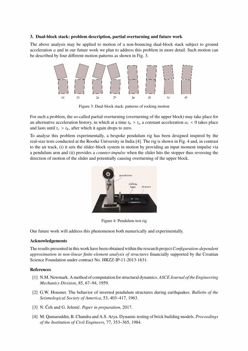
To analyse this problem experimentally, a bespoke pendulum rig has been designed inspired by thereal-size tests conducted at the Roorke University in India [4]. The rig is shown in Fig. 4 and, in contrastto the air track, (i) it sets the slider–block system in motion by providing an input moment impulse viaa pendulum arm and (ii) provides a counter-impulse when the slider hits the stopper thus reversing thedirection of motion of the slider and potentially causing overturning of the upper block.
Figure 4: Pendulum test rig
Our future work will address this phenomenon both numerically and experimentally.
AcknowledgementsThe results presented in thiswork have been obtainedwithin the research projectConfiguration-dependentapproximation in non-linear finite-element analysis of structures financially supported by the CroatianScience Foundation under contract No. HRZZ-IP-11-2013-1631.
References[1] N.M.Newmark.Amethod of computation for structural dynamics.ASCEJournal of theEngineering
Mechanics Division, 85, 67–94, 1959.
[2] G.W. Housner. The behavior of inverted pendulum structures during earthquakes. Bulletin of theSeismological Society of America, 53, 403–417, 1963.
[3] N. Čeh and G. Jelenić. Paper in preparation, 2017.
[4] M. Qamaruddin, B. Chandra and A.S. Arya. Dynamic testing of brick buildingmodels.Proceedingsof the Institution of Civil Engineers, 77, 353–365, 1984.