Embed Size (px)
Citation preview

Rocket Propulsion
Prof. K. Ramamurthi
Department of Mechanical Engineering
Indian institute of Technology, Madras
Lecture 30 Analysis of Gas Generator and Staged Combustion Cycles and introduction to injectors
In the last class, we derived an expression for the fraction of the total propellant flow into
the gas generator as a function of R, the overall mixture ratio that means, from the tank
whatever be the oxidizer, which is being supplied to the fuel which is supplied. We also
had the other parameters as density of the fuel, which we called as rho f, density of the
oxidizer rho naught, the pressure increase across the pump delta p so much Newton
meter square, the value of Cp and the expansion ratio in the turbine.
(Refer Slide Time: 00:58)
What does this expression tell us? Immediately we see f increases as delta p goes up,
delta p is the pressure increase across the pump. That means, for a high pressure engine
and a high pressure engine will demand a higher value of pressure at the inlet to the
engine. Therefore, the pump pressure ratio must be high. Therefore, the fraction of the
propellant f, which goes into the gas generator, must be high. If we want to plot, the
value of f as a function of delta p across the pump, the trend of the change of delta p

should be similar, to the trend of the change of chamber pressure.
We can write here pc as the chamber pressure instead of delta p on the x axis. The
fraction of propellant, which is required to flow through the gas generator, should
increase as the chamber pressure increases; this is first observation; is this alright?
How will the fraction change with the overall mixture ratio? If overall mixture ratio is
higher that means, the value of ‘f’ will be smaller, because we have R in the
denominator. This R in the numerator is modulated by the density and multiplied by
some number and added to a quantity; therefore, the R in the denominator tends to be
stronger or rather the value of f will decrease as R increases.
(Refer Slide Time: 02:37)
And therefore, we can represent the influence of the overall mixture ratio if we plot delta
p over here or which is same as we said as pc; may be we will get a series of lines for
different values of R and as R increases the value of f decreases. Let us try to interpret
these two graphs which I have just drawn. We find that as the pump pressure increases or
equivalently the chamber pressure increases, we need more of the fraction of the
propellant to be introduced through the gas generator and what is the implication.

(Refer Slide Time: 03:17)
The total impulse now I call it is total specific impulse is equal to f through your gas
generator whatever was available, plus 1 minus f of through the main chamber.
(Refer Slide Time: 03:37)
And we found in the case of a gas generator cycle, if we increase this f the Isp,T will
decrease. In the gas generator cycle, if we plot the total specific impulse of the total
engine system as a function of let us say the value of pc, in the case of the gas generator
cycle net Isp will fall with pressure if the specific impulse of an engine will not increase
with chamber pressure.
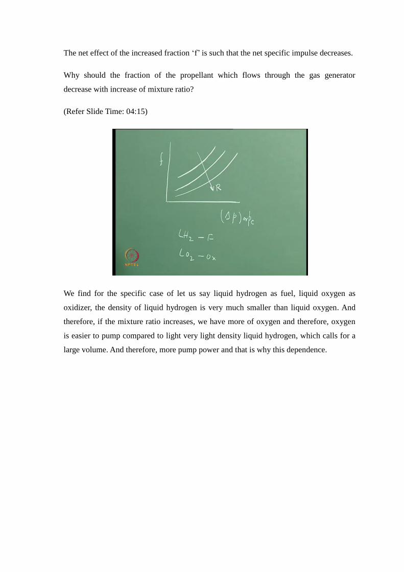
The net effect of the increased fraction ‘f’ is such that the net specific impulse decreases.
Why should the fraction of the propellant which flows through the gas generator
decrease with increase of mixture ratio?
(Refer Slide Time: 04:15)
We find for the specific case of let us say liquid hydrogen as fuel, liquid oxygen as
oxidizer, the density of liquid hydrogen is very much smaller than liquid oxygen. And
therefore, if the mixture ratio increases, we have more of oxygen and therefore, oxygen
is easier to pump compared to light very light density liquid hydrogen, which calls for a
large volume. And therefore, more pump power and that is why this dependence.

(Refer Slide Time: 04:55)
Therefore, let us summarize these two observations, which I show through these slides
here. We had derived the expression that f is equal to this expression, which I had written
on the board earlier.
(Refer Slide Time: 05:01)
And we said as ‘f’, the fraction of the propellant which flows through the gas generator,
as a function of p increases. We are considering the delta p as 0.1 MPa, 1 MPa, 10 MPa,
100 MPa and f increases. You know it is a linear with respect to delta p, but since we use
a logarithmic scale the higher values of pressures get compressed as they increase on the

X axis and hence the curve. As R increases the value of ‘f’ decreases.
(Refer Slide Time: 05:34)
If the chamber pressure is chosen as a parameter and we plot fraction f as a function of
the overall mixture ratio, for a high chamber pressure we have a large fraction ‘f’. The
mixture ratio of the gas generator is assumed to be 0.6. And for eta for the turbine pump
system is 0.6; the temperatures of gas generator is 900 Kelvin. We find that for a high
value of chamber pressure we require large flow rates through the gas generator whereas,
if the chamber pressure is small we need a small flow rate.
What is the implication of this? I think this is something which you all can readily work
out and see? The implication is if my chamber pressure is small, then what is it we find?
The value of ‘f’ is negligibly small.

(Refer Slide Time: 06:48)
If ‘f’ is small you know I do not really spend so much of propellant in the gas generator
and therefore, the Isp is not much adversely affected. However, if the value of ‘f’ is
going to be large, we are pumping so much fuel and oxidizer into the gas generator, that
the net Isp comes down. Rather if I have to make a plot now of the value of the net Isp as
a function of let us say the chamber pressure, I find that Isp monotonically decreases
with increase of pressure if the influence of pressure on specific impulse is not
accounted. If Isp is plotted as a function of the overall mixture ratio, we find that at low
chamber pressures the Isp decreases with mixture ratios. At higher pressure, we get an
increase followed by a drop. This is because, though the Isp is more due to the enhanced
value of pressure, the large fraction of propellants used in the gas generator at the rich
mixture ratio causes the Isp curve to droop.
Whereas if we allow the net propellant into the main chamber like we have in a staged
combustion cycle, may be in that case, we will get a small increase for the stage
combustion cycle. This is value is at a chamber pressure of 1 MPa i.e.,10 bar. But if we
have to operate the engine at a value of let us say 10 MPa, which is slightly higher
pressure, the GG cycle will give a performance over here, slightly higher performance,
but my stage combustion cycle is going to give me a performance, which is going to be
very much higher, because this increase of Isp came from pressure. In fact, for the GG
cycle, the performance drops off rapidly with overall mixture ratio since the mixture ratio
in the main chamber becomes very much oxidizer rich. The stage combustion cycle will

give a high performance even at the higher mixture ratios. If we go to still higher
pressures, this we are talking of 10 MPa, and if we go to something like 20 MPa or 200
bar may be the G G cycle will come down like this, because I am losing lot of lot of my
impulse in the auxiliary nozzle, whereas, my stage combustion cycle will be much better.
In other words at low pressures by operating a gas generator cycle we do not lose much;
whereas at high pressure we keep losing more and more to the extent that the G G cycle
is not competitive any more.
(Refer Slide Time: 09:32)
Therefore, we can say that a gas generator cycle is more suited for low pressure engines
whereas, the stage combustion cycle or an expander cycle which uses all the propellant
in the main chamber is more adapted for high pressure engines. Of course, if we talk in
terms of this stage combustion cycle, we need a high pressure pump and maybe we will
examine it when we talk in terms of pumps and turbines. To repeat again: let us go
through this in the slides, because this tends to be a little important.

(Refer Slide Time: 10:17)
All what I am saying is. If I operate a gas generator cycle at a small value of pressure,
this is the net value of specific impulse I get. If I operate the same engine on a stage
combustion cycle at low pressure, I get a slightly better performance, because I have not
lost very much, because f is still small. I have lost something from stage combustion
cycle to gas generator cycle; therefore I still find gas generator cycle is lower than stage
combustion cycle, but the loss in performance of the gas generator cycle is small.
The loss is small, because f might be something like 0.01 or something of this order. If I
go to higher pressure what is it I find? At higher pressure the gas generator, because the
pressure is high, I get a slightly higher value of specific impulse, but at the same value
the stage combustion gives me a much higher value of specific impulse. That means, by
operating at something like 100 bar, I lose if I were to operate the rocket in a gas
generator cycle and I will have a lower value of specific impulse whereas, if I operate it
in a stage combustion cycle, I get a higher value. Please remember that the x axis in this
graph represents, the overall mixture ratio R, and as R increases, the quantity of the
oxidizer increases, since we are in an oxidizer rich region there is a fall in pressure as the
mixture ratio increases.
If I go to something like 20 MPa say 200 bar, because of the very high value of ‘f’ the G
G cycle has this performance whereas, I do not lose anything in stage combustion cycle
and the performance is very high in terms of specific impulse. We loose a lot by

operating a liquid propellant engine in a gas generator cycle at high pressures.
If we have a low pressure engine, may be a G G cycle is adequate while if we have a
high pressure engine it is necessary to go for stage combustion cycle.
(Refer Slide Time: 12:20)
And generally for cryo engines a chamber pressure upto about 10 MPa or 100 bar seems
to be the limit for a gas generator cycle, above this to operate a gas generator cycle you
will lose more then what you can gain. And this follows from a cycle analysis.
To be able to complete the cycle analysis, we must also find out why the droop or fall in
Isp with the overall mixture ratio especially for the gas generator cycle. It fell so rapidly
at higher pressures. The reason is that the overall mixture ratio in the main combustion
chamber becomes very oxidizer rich since the gas generator demands fuel rich mixtures.

(Refer Slide Time: 13:01)
Like for instance we had a gas bottle; from the gas bottle, we had the tanks. What did we
do? We took little bit of the oxidizer, little bit of the fuel into the gas generator, and this
is mind you very fuel rich. And therefore, we are bleeding more and more of it. What
happens when I bleed more and more of the fuel rich mixture, the mixture ratio of the
main engine keeps increasing, because I am drawing lot of fuel into gas generator and
starving the main engine of the oxidizer. Therefore, this becomes oxidizer rich and then
again what is the dependence C star or Isp with respect to mixture ratio. It comes down
after an optimum mixture ratio. And that is why the droop in the curve.
(Refer Slide Time: 13:56)

Therefore, let us quickly derive an expression what will be the value of the mixture ratio
in the main thrust chamber for a gas generator cycle a function of R and ‘f’.
The value of mixture ratio in your main chamber is required. Let us picture this gas
generator cycle in our minds. We say Rmc is equal to m dot o minus m dot o in the gas
generator which is not available in the main chamber divided by m dot h minus m dot h
through the gas generator. We consider the specific case of hydrogen oxygen as
propellants. And this I can now write as equal to m dot o into 1 minus m dot o of G G by
m dot o. Similarly, we express hydrogen as m dot h into 1 minus m dot h through G G by
m dot h. And how do I get this value of m dot o which is going through the gas generator
or m dot h which is going through the gas generator to the total oxygen and hydrogen
flow. We have already done something very similar, in the last class.
(Refer Slide Time: 15:38)
Let us take a look at m dot h through gas generator plus m dot o through gas generator, is
equal to the total propellant flow in the gas generator. This is equal to m dot h through
the gas generator, let us say m dot h through the gas generator, into 1 plus RGG. And
similarly, we can we can write an expression for m dot o plus m dot h which is the total
mass of propellants. And we can write this as equal to m dot h into 1 plus R. And now we
know what is the fraction f. Fraction f is equal to m dot h through the G G into 1 plus
RGG, divided by m dot h through your main engine, into 1 plus R.

(Refer Slide Time: 17:04)
Or rather from this we get m dot h into G G divided by m dot h is equal to f into 1 plus R
divided by 1 plus RGG. And now I can also write, if this is ok, m dot o GG divided by m
dot o. How do we convert m dot h,GG to this m dot o,GG. Multiply it by RGG. Therefore m
dot o GG becomes equal to m dot h GG into RGG. And m dot o by m dot h is equal to R
therefore, m dot o is equal to R m dot h. Therefore, this becomes RGG by R into the same
value gets repeated as f into 1 plus R divided by 1 plus RGG. And now I substitute these
values of m dot h, GG by m dot h from the first expression, and I take m dot o GG by m dot
o from the second expression in the expression for the mixture ratio in the main chamber.
(Refer Slide Time: 18:18)

And I get the value of R for the main chamber is equal to I get and m dot o minus m dot
o GG by m dot h minus m dot h,GG. This is equal to R here mass of oxidizer by fuel into, 1
minus I take from the second expression, RGG by R into f into 1 plus R by 1 plus RGG
divided by 1 minus f into 1 plus R, divided by 1 plus RGG. I think we must learn to do
such derivations for an analysis.
We have obtained the mixture ratio in the main engine as a function of the mixture ratio
in the gas generator and the value of ‘f’. And for combination of parameters like RGG is
being about 0.6 and for different values of R, we can plot RMC as a function of f. We find
that well as ‘f’ increases the value of the mixture ratio in the main chamber keeps
increasing and as the value of R increases, it also increases.
If the value when f is equal to 0, the mixture ratio in the main chamber is same as the
overall mixture ratio. This is the condition for the stage combustion cycle, and the
expander cycle engine, wherein there is no loss in the gas generator, because gas
generator supplies the propellant back into the main chamber. That means, when f is
equal to 0, we regain my solution. As ‘f’ increases the mixture ratio in the main chamber
keeps increasing. And if it increases to a very large value you come to a situation where
in you cannot operate the engine.
(Refer Slide Time: 20:40)
In other words what we just now told was R versus the specific impulse or C star goes
like this. We start operating at these low values and that is why the specific impulse or

equivalently C star or the total performance keeps falling. This is how we compare the
different feed system cycles such as the gas generator cycle, the stage combustion cycle
the expander cycle, etc. We will quickly sum up by telling the following: for pump feed
systems, we could operate the liquid propellant rocket as a gas generator feed system, as
a stage combustion cycle or as an expander cycle or some other cycle
(Refer Slide Time: 21:17)
We found that the stage combustion cycle is something like a topping cycle; we find the
G G suffers at high chamber pressures, because the value of the fraction of the propellant
is used to drive the turbine is not properly utilized. And what is driven out is at a low
value of expansion through an auxiliary nozzle; whereas, in the topping cycle the
mixture ratio of the main chamber is same as the overall mixture ratio. In the case of the
GG cycle, the mixture ratio in the main engine and the overall mixture ratio are related
through f and RGG.
For high pressure of operation, the staged combustion cycle is particularly useful because
we gain the advantages of high pressure, but we will have to take a look at the design of
pumps after two or three classes. I think this is all about the gas generator and the stage
combustion cycles. And the expander cycle we cannot operate at high pressure, because
we use only a vapor that is generated by heating with the chamber, but this also has some
powerful implications. Maybe we will take a look at some examples on why we cannot
operate the expander cycle at high pressure. In an expander cycle, we are using a

chamber which runs hot. We have limited amount of heat transfer possible in a chamber.
And therefore, we cannot have very high power and since I cannot have very high power
expander cycle also operates at low chamber pressures.
But, its performance will be very much higher than the gas generator cycle, because I do
not use any amount of propellant in the gas generator, which is not effectively expanded.
I think this is all about the feed system cycles.
Let us go to the next element of our discussion namely the thrust chamber.
(Refer Slide Time: 23:37)
We need a gas bottle and we could find out how much mass of gas is required. We said
well propellants are stored in tanks, then we said we need something like a pump here,
we need a pump here, which is driven by the turbine and we still have to cover this part
on pumps. We come to the chamber wherein fuel and oxidizer are injected into the
chamber. That means, we have a fuel to be injected into the chamber, similarly the
oxidizer. We need to know how combustion takes place in a chamber and of course, we
have considered the nozzle expansion earlier.
We would like to concentrate on this thrust chamber in this class and may be first half of
the next class. What does the thrust chamber consist of? It consists of a device to inject
the liquid into it into it. May be the liquid must evaporate get mixed together and burn
and the products of combustion must get expanded. Therefore, let us consider the first

part namely the injection device. How do you inject the high pressure fuel into the
chamber?
(Refer Slide Time: 24:56)
The injector admits the requisite quantities of liquid fuel and liquid oxidizer at the given
mixture ratio into the chamber. That means, it must have some control of the mixture
ratio. It must it must inject the required quantity of propellants into the chamber. Not
only does it does it admit the liquid fluid at the given mixture ratio, it must also sort of
increase the surface area of the liquid or it must atomize the liquids. What do we mean
by atomize. It must disintegrate the liquid fuel into something like fine droplets or let us
say droplets, which can easily evaporate. Not only must the injector assist in
vaporization, but the third point is it must help the evaporated vapor of fuel and oxidizer
to mix together. It must ensure that it will push the fuel and oxidizer in some way such
that may be the vapor will mix together. Once mixed, the fuel and oxidizer can
chemically react and burn. In some cases you need an igniter to start the burning, but
once started the hot environment can always promote the chemical reactions and the
burning. Therefore, the requirement of an injector is it must admit suitable quantities to
give the correct mixture ratio and mix the vapors.

(Refer Slide Time: 26:37)
And we are interested in a given mixture ratio. Let us not forget this graph we say C star
or Isp as a function of mixture ratio. It is in the fuel rich region that we get a much higher
specific impulse. Therefore, we are interested in this value of mixture ratio. The injector
must also admit the required amount of fuel oxidizer and fuel such that we get the thrust
as desired, get this mixture ratio and it must also break up the liquid into fine droplets.
And mix them together this is what an injector should do. Therefore, let us start with the
simplest form of injectors, which we are familiar and let us let us build up on it.
(Refer Slide Time: 27:14)

In the figure, I show a shower head. We use it daily for bathing..
(Refer Slide Time: 27:23)
Let us take a look at the streams of water generated. The streams get broken into drops
later on.
(Refer Slide Time: 27:31)
We have something like a like a head and a number of holes or orifices. I brought a
shower head and take a look at it.
You know this is something like what we use in our shower you know you have the

water coming from the water line, water collects in this region known as manifold and
then you have a series of holes or orifices. And this is what we called as a manifold in
which water collects. The pressure in the manifold is higher than the ambient pressure
and water is forced through these orifices. Let me just sketch this shower head on the
board. It tends to be very illustrative of the different types of injectors which we use.
(Refer Slide Time: 28:20)
I have a surface with a number of fine holes. This is what was said to be a head, which
has lot of this orifices. You have something like a place through which the liquid is
admitted. And we have spacing between these two holes or streams. And this is where we
admit the water and this is what we called as a manifold. What does the manifold do? It
admits and maintains the pressure over here such that water squirts out through these
holes here. And you know that very often you find if your shower head is not properly
designed and you are taking a bath let us say, you do not get the streams of water hitting
you. If your shower head is very well designed you find the jets of water come like this
as laminar streams.
If it is not very well designed, you find some drop drops of water coming like this, may
be at the same value of velocity. We would like to have an injector which is something
like a shower head, but which is able to produce droplets and this is one type of injector.
And this type of injector is known as a shower head injector. Let us again go through a
shower head injector. We have manifold in which the water collects and forces through

the orifices.
(Refer Slide Time: 30:06)
Therefore, we are looking for something like flow through an orifice or a hole. The
shower head consist of lot of these holes through which may be water is being pushed
through when we are taking a bath. And a similar scheme can be used in case of liquid
propellants. You have the manifold here. We have the set of orifices here. We could
divide it the manifold into partitions and admit the fuel in some region and admit the
oxidizer in the other portions. We allow them to mix in this region and evaporate and
burn. This becomes the shower head injector. Now, we would like to find out about the
flow through the orifices?
We show one such hole or orfice, this is the manifold here and we have lot of such holes.
This is the manifold; since its volume is large, the liquid as such collects in this manifold
here. That is in the region in the chamber preceding the orifices therefore, the pressure in
the chamber is the supply pressure to the hole or orifice. The velocity is almost zero here
considering the large volume. And the water squirts out through these particular holes.
Therefore, we have the manifold; in the manifold be the pressure is p and the velocity is
almost zero. And in the case of rocket the liquid get supplied into the chamber pressure,
from the orifices. We have chamber pressure downstream of the orifice and the supply
pressure ahead of it in the manifold. We are interested in finding out the flow through the
orifices.

(Refer Slide Time: 32:35)
If we have let us say nf orifices for fuel and I have no orifices for oxidizer, we want to
find the flow rate through the orifices and the mixture ratio. We would like to find out
into flow per orifice and multiply by the number of orifices to determine the net flow
rates.
How do we find the flow through the orifices. We look at this scheme again. We find that
there is lot of science even in a small orifice flow, which we need to understand. The
thing is that we have an orifice whose edges are sharp. We call it as a sharp edged orifice.
How do we make an orifice for the particular shower head? Each of the holes is drilled
on a plate.
If we drill a hole and remove what are the burs at the edges, we get the sharp-edged
orifice. When the fluid enters the sharp edge from the manifold wherein the velocity is
almost zero, it accelerates and sort of contracts over here; The liquid separates from the
walls of the orifice, contracts to a minimum and then reattaches later to the walls. The
minimum contracted area is called as veena contracta. In other words this is the where
the liquid is flowing. If I have my shower head which has a very small dimension that
means a very thin plate instead of having a given length of the orifice. The separated
flow leaves the orifice.
The flow is coming from the manifold contracts and goes straight out. That means, the
flow does not reattach back to the wall of the orifice. In fact, the flow is separated and

the effective area of flow is going to be much lower than the area of the orifice. If we
denote the area of orifice by A0, the area of flow is going to be much lower. How do we
write out the expression for the mass flow through the orifice. Let us try to derive a
simple expression.
(Refer Slide Time: 35:32)
You would have done this in your fluid mechanics class; but let us just do it again. We
have a manifold and we are considering the case of a single orifice. The pressure in the
manifold is higher than the chamber pressure. The difference in pressure is equal to delta
p. We want to write an equation for the velocity here at the exit of the orifice when the
entrance velocity at the manifold is zero. We denote it by V. We use the Bernoulli
equation, the flow is liquid at small values of velocities therefore it is incompressible and
the density rho is a constant. Therefore, we have p by rho plus V1 squared by 2 0 plus we
have gz1, where z1 is height above datum at he entry to the orifice. The value equals here
is pC by rho plus V squared by 2 plus gz2 where z2 is the height above datum over here.
Since the orifice is small in length, we can take gz1 is equal to gz2, because there is not
much change between z1 and z2. And therefore, we immediately get the square of the
velocity of the stream leaving the orifice equal to 2 into delta p by rho. That is V is equal
under root of 2 into p minus pC by rho that is under root of 2 delta p by rho..
The mass flow rate is equal to the above velocity multiplied by the area of the orifice into
into density. The orifice cross sectional area is A0, and we get the mass flow rate as A0

into under root 2 into delta p into the value of density. This is the mass flow rate for a
simple sharp edge orifice.
But we just saw that the orifice sometimes flows full like it is attached over here, there is
some friction over here and sometimes it flows separated from the walls of the orifice.
(Refer Slide Time: 37:44)
Therefore, there are different regimes of flow. Depending on the type of flow through the
orifice, whether attached in which case a it runs full or whether it is detached in which
case it does not run full, the cross sectional area of the flow will change. We find that
based on the orifice area which is A0, we can define a coefficient namely a discharge
coefficient as equal to something based on the ideal flow or ideal mass flow what we
could have and the actual flow. We call it as a discharge coefficient and what is the ideal
flow? When the entire area of the orifice that is the flow is running full when there is no
friction at the wall, I could have the total flow corresponding to delta p. In practice we
have friction at the wall, sometimes the flow is separated and the flow may not be totally
axial. The actual flow will be less than ideal flow and therefore, we have a discharge
coefficient Cd which will always be less than one.
To be able to arrive at this value of discharge coefficient we write in terms of mass flow
rate m dot in the ideal case. What is the value of the ideal mass flow rate? We have flow
runs full through the area A0, the velocity of flow depends on the pressure drop namely
under root of 2 into delta p by rho into the density rho. And therefore, we get the ideal

flow rate as equal to A0 into under root 2 delta p into rho. In practice since you do get
separated flow and frictional effects you do not know what this area of this separated
flow, you base your total flow on the total area A0. The actual flow would therefore be
equal to m dot given by Cd into A0 into under root 2 delta p multiplied by the density.
The flow is incompressible and therefore the density is constant. This is the value of the
flow which takes place and is given by this particular expression. Let us again recall that
A0 is the area of the orifice through which flow is taking place, Cd is the discharge
coefficient, rho is the density of the liquid, and delta p is the pressure drop across the
particular orifice or hole.
(Refer Slide Time: 40:51)
It must be remembered that the value of the discharge coefficient Cd depends on the
regimes of flow through the orifice. What do we mean by regimes of flow? The flow
sometimes runs full such as it happens when the orifice is large, sometimes with
cavitation it gets separated or when the orifice is very very thin, the flow cannot reattach.
And for the different conditions we would like to examine the value of Cd which we now
do.

(Refer Slide Time: 41:28)
We should not spend too much time on it, because we are shifting the topic from liquid
propellant rockets to once particular element of it. This shows your injector head or
shower head wherein you have lot of these small holes through which flow is taking
place.
(Refer Slide Time: 41:32)

(Refer Slide Time: 41:45)
If we do experiments and allow flow at different values of Reynolds number, we have as
flow rate increases, an increase of the Reynolds number. We see in the figure the jet
issuing from an orifice at Reynolds number of about 16,000 32,000 and 33,000. You find
that at smaller values of Reynolds number the texture of the jet is quite smooth; like you
stand under a shower you can see silvery water coming down. At some Reynolds number
it tends to become a little turbulent and rough. At yet higher values of Reynolds number
it becomes violently rough. Let us examine the flow further.
(Refer Slide Time: 42:15)

When we have a long orifice the veena contracta is followed by the flow subsequently
attaching to the orifice walls. Sometimes even for the same length the flow goes straight
through; it does not attach. Whereas for a small length the separation is understandable,
because if we were to cut the orifice much before it attached, well there is no way of
reattachment. What could be the reason for flow not attaching for the longer orifices?
(Refer Slide Time: 42:41)
When flow is taking place at high velocities, and we further enhance the velocity by
increase of the pressure drop, the static pressure of the liquid decreases. If the pressure
decreases to a value equal to or less than the vapor pressure of the liquid itself then
cavities begin to form in the liquid. Once cavities begin to form in the liquid a
reattachment like this is not possible and the flow separates out even for the longer
orifices. Such type of flow is known as cavitated flow, and some books call it as super
cavitation. Though the flow should have reattached, the pressure here has gone to a low
level wherein the pressure of the liquid is equal to or less than the vapor pressure of the
liquid andvapor gets generated and the flow separates.
Therefore, essentially we talk in terms of three types of flows. Reattached flow when we
have long value of length to diameter orifices, a flow which is separated when we have
high velocities or cavitation taking place and separated flow for small length to diameter
orifices. Therefore, we could get different values of discharge coefficients accordingly.

(Refer Slide Time: 44:01)
And if we do an experiment starting at low value of Reynolds number wherein I get an
attached flow, we get a high value of discharge coefficient since the flow is the attached
and the whole flow area is contributing to the flow. Thereafter the discharge coefficient
decreases as the Reynolds number increases because of the frictional losses and losses
due to turbulence. At some value of Reynolds number cavitation starts and the flow
separates to give a smaller discharge coefficient. The small discharge coefficient persists
at still larger Reynolds numbers.
And now if we start reducing the pressure or reducing the velocity from the high
Reynolds numbers, the discharge coefficient does not increase in the same way it
decreased with increased Reynolds numbers. The flow retains the memory of the
separated flow and continues to be separated and abruptly jumps back to give high
values of discharge coefficients. That means, even a sharp edged orifice which makes the
shower head injector can give a multitude of discharge coefficients.

(Refer Slide Time: 44:49)
When we start the experiment and measure the Cd as the function of Reynolds number
we initially get attached flow for which Cd is near to 1. This is because the flow comes
and gets attached and the fully attached flow gives discharge coefficients with losses due
to friction drop and turbulence. But when cavitation starts, the flow separates. The flow
separates giving low Cd when in the forward direction of increasing Reynolds number.
When we reduce the pressure the discharge coefficient does not trace back the original
values and we have a zone for which we get two values of discharge coefficients. This
zone is known as the hysteresis zone.
If we have the length of the orifice to the diameter of some value wherein it is just near
the attachment, the jet issuing from it would have certain characteristics. At the threshold
value the flow attaches and reattaches with the result that there is a flip in the jet and
change in the discharge coefficient. The flip is between attached region and detached
regions of flow.

(Refer Slide Time: 46:29)
Therefore, even to choose a shower head we need to understand the mechanics of flow.
Normally the shower heads are such that the length of your orifice is greater than the
diameter so as to get the attached flow. The orifice length L to the diameter of the orifice
D is known as aspect ratio of the orifice and is about 2.
For control purposes whenever you want a controlled flow experiment we use a very thin
orifice with razor type of blade in which the length is a very small number compared to
the diameter. And the flow in this case is always detached. Therefore, you must choose
whether you want detached flow or attached flow and accordingly choose the
dimensions. And therefore, we say that flow through orifices depends on the length to
diameter ratio, because the Cd depends on it.

(Refer Slide Time: 47:16)
We normally choose sharp edged orifices. If you go to the market and you want to buy a
shower head for bathing, why not choose a shaped orifice which provided streamline
flow? This could provide attached flow without any flow separation compared to the
sharp edged orifices.
(Refer Slide Time: 47:35)
Let say an orifice at the exit of the manifold could be shaped for a smooth entry. Why not
make such orifice which provides smooth streamline along the flow. This will give full
flow. But to fabricate such orifices is difficult especially in large numbers. We could have

an orifice which is like this; however, the next one would be different and to obtain
reproducibility in something like a shaped orifice is more difficult. And we are going to
have 40 holes in a rocket we may have 80 holes or 100 holes or 200 holes. To get so
many holes drilled with shaped orifices is difficult and therefore, we normally use sharp
edged orifices.
We have a manifold in which we fuel and oxidizer. We have a series of orifices through
which oxidizer flows and fuel flows, and that is how we make a shower head injector.
We would like to calculate the mixture ratio formed by the injector.
(Refer Slide Time: 48:56)
The mixture ratio R is equal to the mass flow rate of oxidizer to the mass flow rate of
fuel. Therefore the value of R is equal to Cd for the orifice into the number of oxidizer
orifices, into the area of each oxidizer orifice, into under root of 2 into delta p across the
oxidizer orifice into the density of the oxidizer divided by the Cd of the fuel orifice into
number of fuel orifices into area of the each fuel orifice into under root of 2 of delta p
across the fuel orifice into rho of the fuel. If I have a shower head which has common
delta p and Cd for both the fuel and oxidizer orifices, the terms cancel out. This is how
we obtain the mixture ratio.
This is all about the simple way of injecting fuel in a rocket chamber using what we call
as a shower head. This shower head teaches us one more lesson. We had said that this is
the manifold and this is the orifice. We have a particular manifold volume. What should

be this volume in a liquid propellant rocket. Should it be large or small? From fluid
mechanical considerations if the volume of manifold is large then I will have the same
pressure for all the holes over here. If I have a very small manifold volume, the holes
which are at the center near the tube inlet will get the high pressure the others will get a
low pressure.
Therefore, from fluid mechanical considerations we should have a volume of manifold
which is let us say large in order to get all orifices achieve same inlet pressure and form
similar jets. Let us take an example.
(Refer Slide Time: 51:22)
Supposing I have a multi-story building and I want to supply water from the top which is
on the 10th floor. And I want to supply uniformly to all the floors i.e. to all the
apartments. If I put a common manifold tube or a tube for supplying water, a person on
the 1st floor will get water at high pressure while a person on the top floor will hardly get
water. How do we ensure uniform supply and this is the same problem for the different
orifices in the injector. How to configure the manifold? The flow resistance for the lower
floors has to be increased by reducing the diameter of the pipe conveying water to the
lower floors.
Or else we could introduce resistance by placing filters or gauges. We place a filter with
larger holes on the top floors. At the bottom floors we place finer filter such that we
introduce some pressure drop such that the supply pressure is same. And so also in rocket
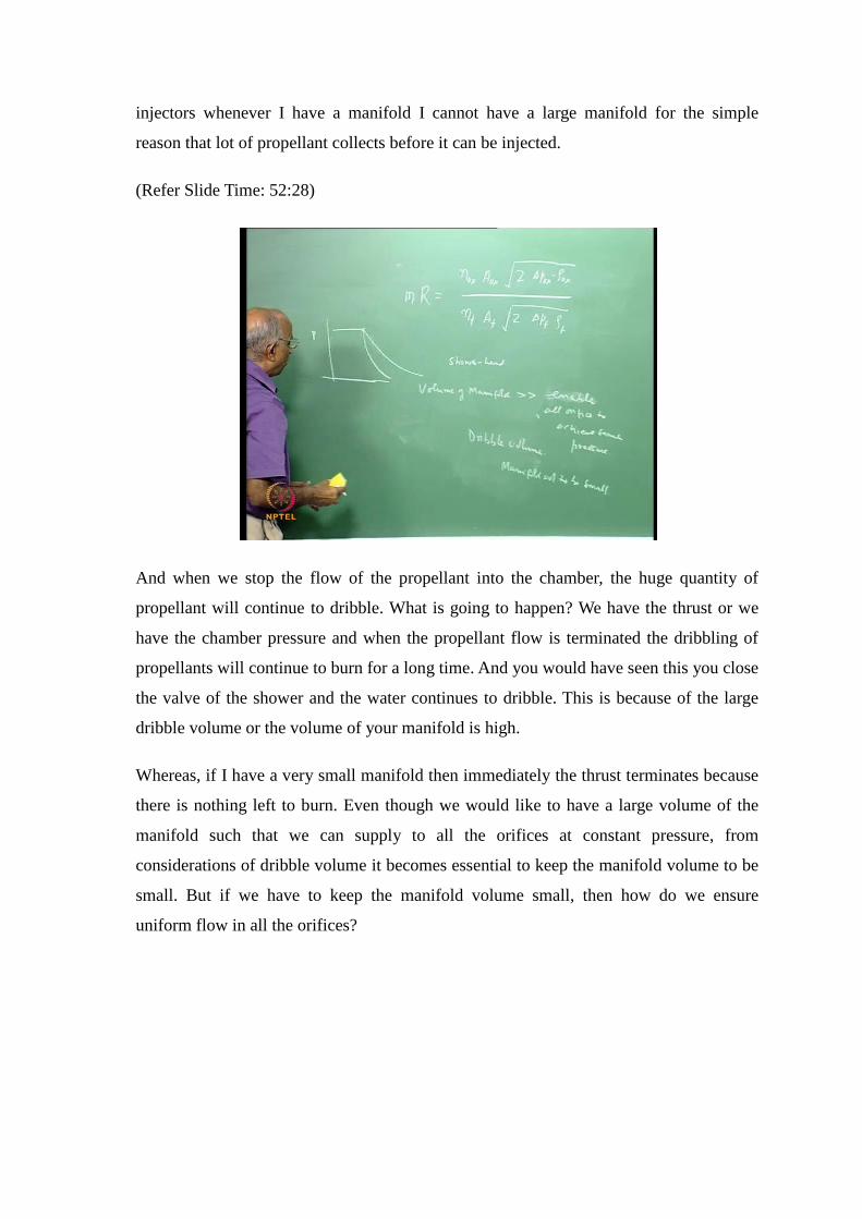
injectors whenever I have a manifold I cannot have a large manifold for the simple
reason that lot of propellant collects before it can be injected.
(Refer Slide Time: 52:28)
And when we stop the flow of the propellant into the chamber, the huge quantity of
propellant will continue to dribble. What is going to happen? We have the thrust or we
have the chamber pressure and when the propellant flow is terminated the dribbling of
propellants will continue to burn for a long time. And you would have seen this you close
the valve of the shower and the water continues to dribble. This is because of the large
dribble volume or the volume of your manifold is high.
Whereas, if I have a very small manifold then immediately the thrust terminates because
there is nothing left to burn. Even though we would like to have a large volume of the
manifold such that we can supply to all the orifices at constant pressure, from
considerations of dribble volume it becomes essential to keep the manifold volume to be
small. But if we have to keep the manifold volume small, then how do we ensure
uniform flow in all the orifices?

(Refer Slide Time: 53:43)
We place something like a sieve over the holes near the inlet and decrease the pressure at
the inlet to the orifices and in regions away on the periphery we communicate the
pressure without any obstruction. These are some common methods used in the design
of shower head injector.
(Refer Slide Time: 54:08)
But shower head injector is something like a weak injector, because as you know the jets
formed are all parallel. It takes some definite time for it to atomize and form droplets, but
you want droplets as early as possible. Mixing of the fuel and oxidizer is also difficult.

And though some of the earlier designs in rockets liquid propellant rockets use shower
head injectors, at the present point in time we never use the shower head injector.
What is it that we do to improve it? Instead of jets being parallel we make them interact
with each other. That means we have impinging jets. And once you impinge jets we form
something like a fan. We will look at the different injection devices in the next class and
also look at some of the problems which we face in the combustion chamber.
In today’s class, we started with the gas generator cycle. We looked at the deficiencies of
a gas generator cycle. Namely some propellant gets wasted which is not fully utilized. A
stage combustion cycle and expanded cycle are preferred especially at high pressures.
Then we just started with the injectors we looked at the shower head injectors. We will
build up on this and look at the other injectors which are used in liquid propellant rockets
in the next class.