Embed Size (px)
Citation preview
G–2
Dimensions are shown: Inches (mm)Specifications and dimensions subject to change
www.ck-components.comG
Ro
ck
er
DT
MiniaturePowerRocker
SPST,DPST
8 Amps,10 Amps
Snap-in
G–66
Rocker
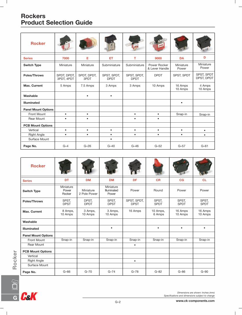
RockersProduct Selection Guide
Series
Switch Type
Poles/Throws
Max. Current
Washable
Illuminated
Panel Mount Options
Front Mount
Rear Mount
PCB Mount Options
Vertical
Right Angle
Surface Mount
Page No.
7000
Miniature
SPDT, DPDT,3PDT, 4PDT
5 Amps
•
•
•
•
G–4
E
Miniature
SPDT, DPDT,3PDT
7.5 Amps
•
•
•
•
•
G–26
ET
Subminiature
SPST, SPDT,DPDT
3 Amps
•
•
•
•
G–40
T
Subminiature
SPST, SPDT,DPDT
3 Amps
•
•
•
•
G–46
9000
Power Rocker & Lever Handle
DPDT
10 Amps
•
•
•
•
G–52
DA
MiniaturePower
SPST, SPDT
16 Amps10 Amps
•
Snap-in
•
•
G–57
D
MiniaturePower
SPST, SPDTDPST, DPDT
4 Amps10 Amps
Snap-in
•
•
G–61
Series
Switch Type
Poles/Throws
Max. Current
Washable
Illuminated
Panel Mount Options
Front Mount
Rear Mount
PCB Mount Options
Vertical
Right Angle
Surface Mount
Page No.
DM
MiniatureIlluminated
Power
SPST,DPST
3 Amps,10 Amps
•
Snap-in
G–74
DM
Miniature2 Pole Power
DPST,DPDT
3 Amps,10 Amps
Snap-in
G–70
DF
Power
SPST, SPDT,DPST
16 Amps
Snap-in
•
•
G–78
CR
Round
SPST, SPDT
10 Amps,6 Amps
•
Snap-in
G–82
CG
Power
SPST, SPDT
16 Amps10 Amps
•
Snap-in
G–86
CL
Power
SPST, SPDT
16 Amps10 Amps
•
Snap-in
G–90
Rocker
G
Ro
ck
er
G–3
Dimensions are shown: Inches (mm)Specifications and dimensions subject to change
www.ck-components.com
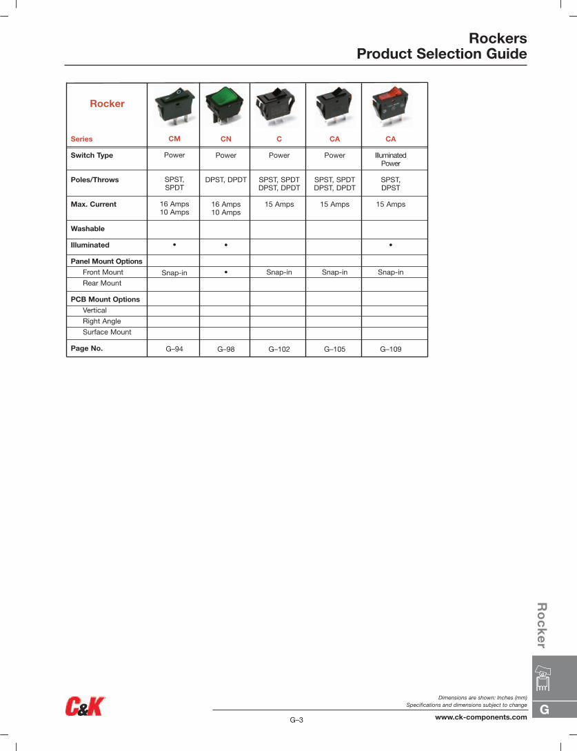
RockersProduct Selection Guide
Series
Switch Type
Poles/Throws
Max. Current
Washable
Illuminated
Panel Mount Options
Front Mount
Rear Mount
PCB Mount Options
Vertical
Right Angle
Surface Mount
Page No.
CN
Power
DPST, DPDT
16 Amps10 Amps
•
•
G–98
C
Power
SPST, SPDTDPST, DPDT
15 Amps
Snap-in
G–102
CA
Power
SPST, SPDTDPST, DPDT
15 Amps
Snap-in
G–105
CA
Illuminated Power
SPST,DPST
15 Amps
•
Snap-in
G–109
Rocker
CM
Power
SPST, SPDT
16 Amps10 Amps
•
Snap-in
G–94
G–4
Dimensions are shown: Inches (mm)Specifications and dimensions subject to change
www.ck-components.comG
Ro
ck
er
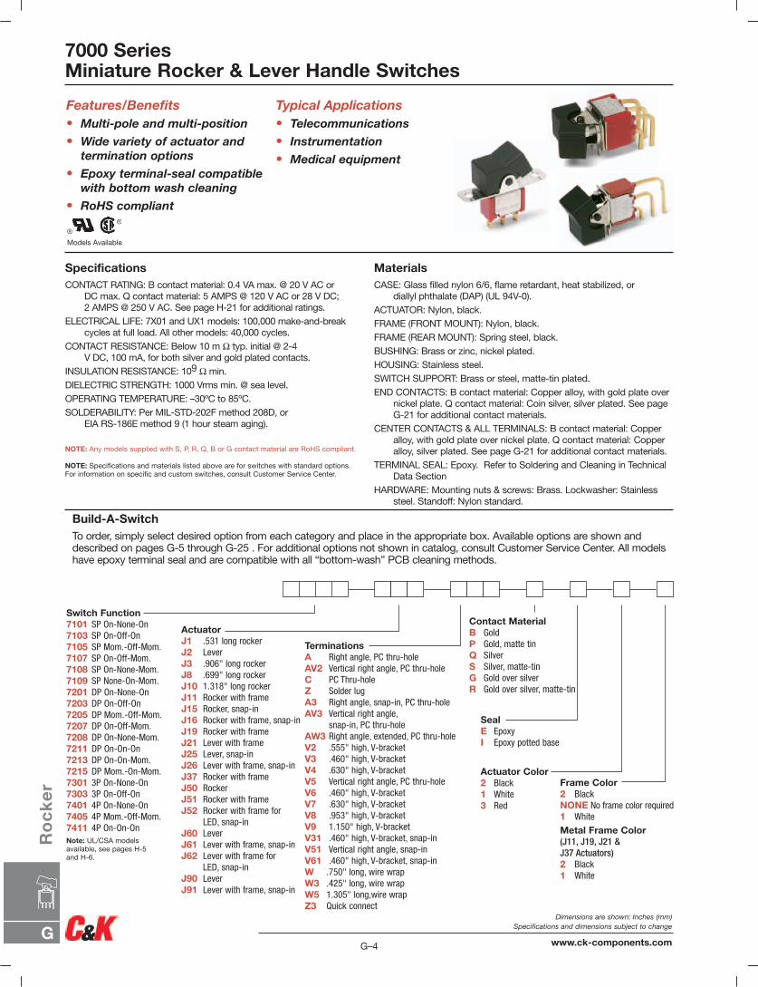
7000 SeriesMiniature Rocker & Lever Handle Switches
Models Available
Features/Benefits• Multi-pole and multi-position
• Wide variety of actuator andtermination options
• Epoxy terminal-seal compatible with bottom wash cleaning
• RoHS compliant
Typical Applications• Telecommunications
• Instrumentation
• Medical equipment
SpecificationsCONTACT RATING: B contact material: 0.4 VA max. @ 20 V AC or
DC max. Q contact material: 5 AMPS @ 120 V AC or 28 V DC;2 AMPS @ 250 V AC. See page H-21 for additional ratings.
ELECTRICAL LIFE: 7X01 and UX1 models: 100,000 make-and-breakcycles at full load. All other models: 40,000 cycles.
CONTACT RESISTANCE: Below 10 m Ω typ. initial @ 2-4V DC, 100 mA, for both silver and gold plated contacts.
INSULATION RESISTANCE: 109 Ω min.DIELECTRIC STRENGTH: 1000 Vrms min. @ sea level.OPERATING TEMPERATURE: –30ºC to 85ºC.SOLDERABILITY: Per MIL-STD-202F method 208D, or
EIA RS-186E method 9 (1 hour steam aging).
NOTE: Any models supplied with S, P, R, Q, B or G contact material are RoHS compliant.
NOTE: Specifications and materials listed above are for switches with standard options.For information on specific and custom switches, consult Customer Service Center.
MaterialsCASE: Glass filled nylon 6/6, flame retardant, heat stabilized, or
diallyl phthalate (DAP) (UL 94V-0).ACTUATOR: Nylon, black.FRAME (FRONT MOUNT): Nylon, black.FRAME (REAR MOUNT): Spring steel, black.BUSHING: Brass or zinc, nickel plated.HOUSING: Stainless steel.SWITCH SUPPORT: Brass or steel, matte-tin plated.END CONTACTS: B contact material: Copper alloy, with gold plate over
nickel plate. Q contact material: Coin silver, silver plated. See pageG-21 for additional contact materials.
CENTER CONTACTS & ALL TERMINALS: B contact material: Copperalloy, with gold plate over nickel plate. Q contact material: Copperalloy, silver plated. See page G-21 for additional contact materials.
TERMINAL SEAL: Epoxy. Refer to Soldering and Cleaning in TechnicalData Section
HARDWARE: Mounting nuts & screws: Brass. Lockwasher: Stainlesssteel. Standoff: Nylon standard.
Build-A-SwitchTo order, simply select desired option from each category and place in the appropriate box. Available options are shown anddescribed on pages G-5 through G-25 . For additional options not shown in catalog, consult Customer Service Center. All modelshave epoxy terminal seal and are compatible with all “bottom-wash” PCB cleaning methods.
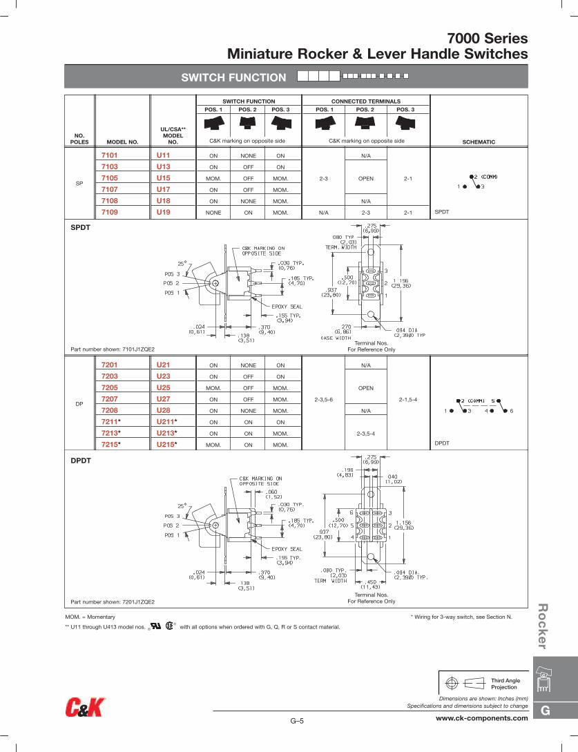
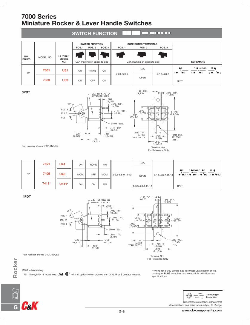
Switch Function7101 SP On-None-On7103 SP On-Off-On7105 SP Mom.-Off-Mom.7107 SP On-Off-Mom.7108 SP On-None-Mom.7109 SP None-On-Mom.7201 DP On-None-On7203 DP On-Off-On7205 DP Mom.-Off-Mom.7207 DP On-Off-Mom.7208 DP On-None-Mom.7211 DP On-On-On7213 DP On-On-Mom.7215 DP Mom.-On-Mom.7301 3P On-None-On7303 3P On-Off-On7401 4P On-None-On7405 4P Mom.-Off-Mom.7411 4P On-On-OnNote: UL/CSA models available, see pages H-5 and H-6.
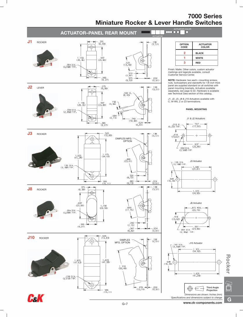
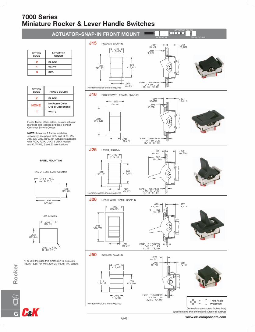
ActuatorJ1 .531 long rockerJ2 LeverJ3 .906" long rockerJ8 .699" long rockerJ10 1.318" long rockerJ11 Rocker with frameJ15 Rocker, snap-inJ16 Rocker with frame, snap-inJ19 Rocker with frameJ21 Lever with frameJ25 Lever, snap-inJ26 Lever with frame, snap-inJ37 Rocker with frameJ50 RockerJ51 Rocker with frameJ52 Rocker with frame for
LED, snap-inJ60 LeverJ61 Lever with frame, snap-inJ62 Lever with frame for
LED, snap-inJ90 LeverJ91 Lever with frame, snap-in
TerminationsA Right angle, PC thru-holeAV2 Vertical right angle, PC thru-holeC PC Thru-holeZ Solder lugA3 Right angle, snap-in, PC thru-holeAV3 Vertical right angle,
snap-in, PC thru-holeAW3 Right angle, extended, PC thru-holeV2 .555" high, V-bracketV3 .460" high, V-bracketV4 .630" high, V-bracketV5 Vertical right angle, PC thru-holeV6 .460" high, V-bracketV7 .630" high, V-bracketV8 .953" high, V-bracketV9 1.150" high, V-bracketV31 .460" high, V-bracket, snap-inV51 Vertical right angle, snap-inV61 .460" high, V-bracket, snap-inW .750" long, wire wrapW3 .425" long, wire wrapW5 1.305" long,wire wrapZ3 Quick connect
SealE EpoxyI Epoxy potted base
Actuator Color2 Black1 White3 Red
Frame Color2 BlackNONE No frame color required1 White
Metal Frame Color(J11, J19, J21 &J37 Actuators)2 Black1 White
Contact MaterialB GoldP Gold, matte tinQ SilverS Silver, matte-tinG Gold over silverR Gold over silver, matte-tin
G
Ro
ck
er
G–5
Dimensions are shown: Inches (mm)Specifications and dimensions subject to change
www.ck-components.com
7000 SeriesMiniature Rocker & Lever Handle Switches
SWITCH FUNCTION
DPDT
2-1,5-4
N/A
OPEN
N/A
2-3,5-4
2-3,5-6
ON NONE ON
ON OFF ON
MOM. OFF MOM.
ON OFF MOM.
ON NONE MOM.
ON ON ON
ON ON MOM.
MOM. ON MOM.
U21
U23
U25
U27
U28
U211*
U213*
U215*
7201
7203
7205
7207
7208
7211*
7213*
7215*
DP
SPDT
2-1
2-1
N/A
OPEN
N/A
2-3
2-3
N/A
ON NONE ON
ON OFF ON
MOM. OFF MOM.
ON OFF MOM.
ON NONE MOM.
NONE ON MOM.
U11
U13
U15
U17
U18
U19
7101
7103
7105
7107
7108
7109
SP
SCHEMATIC
CONNECTED TERMINALS
POS. 1 POS. 2 POS. 3
SWITCH FUNCTION
POS. 1 POS. 2 POS. 3
UL/CSA**MODEL
NO.MODEL NO.NO.
POLES C&K marking on opposite sideC&K marking on opposite side
Terminal Nos.For Reference Only
Terminal Nos.For Reference Only
DPDT
SPDT
Part number shown: 7101J1ZQE2
Part number shown: 7201J1ZQE2
* Wiring for 3-way switch, see Section N.MOM. = Momentary
** U11 through U413 model nos. with all options when ordered with G, Q, R or S contact material.
7000 SeriesMiniature Rocker & Lever Handle Switches
SWITCH FUNCTION
C&K marking on opposite sideC&K marking on opposite side
* Wiring for 3-way switch: See Technical Data section of thiscatalog for RoHS compliant and compatible definitions andspecifications.
MOM. = Momentary
** U11 through U411 model nos. with all options when ordered with G, Q, R or S contact material.
7301
7303
U31
U33
3PON NONE ON
ON OFF ON
7401
7405
7411*
U41
U45
U411*
ON NONE ON
MOM. OFF MOM.
ON ON ON
2-3,5-6,8-9,11-12
N/A
OPEN
2-3,5-4,8-9,11-10
2-1,5-4,8-7,11-10
4PDT
4P
2-3,5-6,8-9
N/A
OPEN
2-1,5-4,8-7
3PDT
NO.POLES
MODEL NO. UL/CSA**MODEL
NO.
SWITCH FUNCTION
POS. 1 POS. 2 POS. 3
CONNECTED TERMINALS
POS. 1 POS. 2 POS. 3
SCHEMATIC
Part number shown: 7301J1ZQE2
3PDT
Terminal Nos.For Reference Only
4PDT
Terminal Nos.For Reference Only
Part number shown: 7401J1ZQE2
G–6
Dimensions are shown: Inches (mm)Specifications and dimensions subject to change
www.ck-components.comG
Ro
ck
er
7000 SeriesMiniature Rocker & Lever Handle Switches
ACTUATOR–PANEL REAR MOUNT
DIMPLESMFG. OPTION
DIMPLES MFG.OPTION
PANEL MOUNTING
J8 Actuator
J3 Actuator
J10 Actuator
J1 & J2 Actuators
2 BLACK
1 WHITE
3 RED
ACTUATORCOLOR
OPTION CODE
Finish: Matte. Other colors, custom actuatormarkings and legends available, consultCustomer Service Center.
NOTE: Hardware: two each—mounting screws,nuts, lockwashers and standoffs for 1/8 inch thickpanel are supplied standard on all switches withpanel mounting brackets. Actuators available separately, see page G-22. Hardware is availablesee Technical Data section of this catalog.
J1, J2, J3, J8 & J10 Actuators available with C, W-W5, Z or Z3 terminations.
J1 ROCKER
J2 LEVER
J3 ROCKER
J8 ROCKER
J10 ROCKER
ACTUATOR COLOR
ACTUATOR
G
Ro
ck
er
G–7
Dimensions are shown: Inches (mm)Specifications and dimensions subject to change
www.ck-components.com
7000 SeriesMiniature Rocker & Lever Handle Switches
ACTUATOR–SNAP-IN FRONT MOUNT
PANEL MOUNTING
J50 Actuator
*
J15, J16, J25 & J26 Actuators
J15 ROCKER, SNAP-IN
J16 ROCKER WITH FRAME, SNAP-IN
J25 LEVER, SNAP-IN
J26 LEVER WITH FRAME, SNAP-IN
J50 ROCKER, SNAP-IN
Finish: Matte. Other colors, custom actuatormarkings and legends available, consultCustomer Service Center.
NOTE: Actuators & frames availableseparately, see pages G-22 and G-25. J15,J16, J25, J26, J50 & J51 Actuators availablewith 71XX, 72XX, U1XX & U2XX models and C, W-W5, Z and Z3 terminations.
* For J50: Increase this dimension to .620/.625(15,75/15,88) for .091/.125 (2,31/3,18) thk. panels.
No frame color choice required
No frame color choice required
No frame color choice required
2 BLACK
1 WHITE
3 RED
ACTUATORCOLOR
OPTION CODE
2 BLACK
NONENo Frame Color(J15 or J25options)
1 WHITE
FRAME COLOROPTION CODE
ACTUATOR COLOR
FRAME COLORACTUATOR
G–8
Dimensions are shown: Inches (mm)Specifications and dimensions subject to change
www.ck-components.comG
Ro
ck
er
7000 SeriesMiniature Rocker & Lever Handle Switches
ACTUATOR–SNAP-IN FRONT MOUNT
PANEL MOUNTING
J51, J60 & J61 Actuators
*
J52 Actuator
*
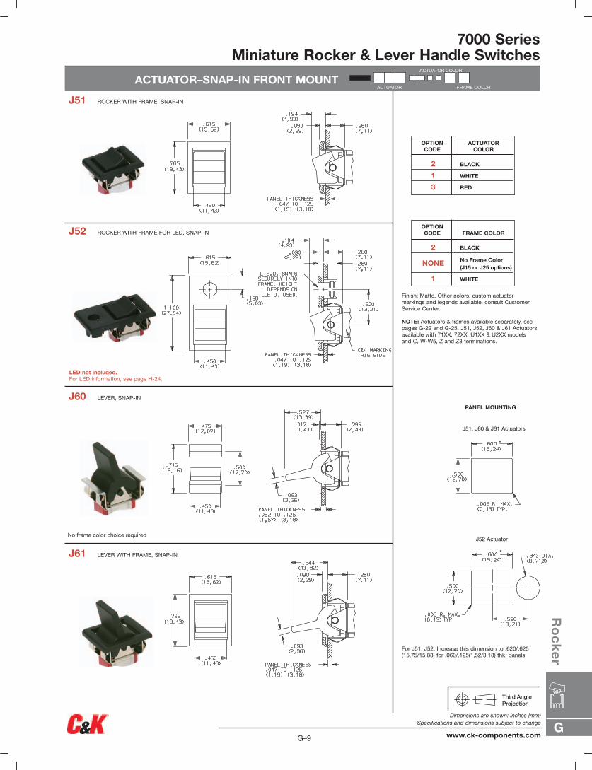
J51 ROCKER WITH FRAME, SNAP-IN
J52 ROCKER WITH FRAME FOR LED, SNAP-IN
J60 LEVER, SNAP-IN
J61 LEVER WITH FRAME, SNAP-IN
Finish: Matte. Other colors, custom actuator markings and legends available, consult CustomerService Center.
NOTE: Actuators & frames available separately, seepages G-22 and G-25. J51, J52, J60 & J61 Actuatorsavailable with 71XX, 72XX, U1XX & U2XX models and C, W-W5, Z and Z3 terminations.
For J51, J52: Increase this dimension to .620/.625(15,75/15,88) for .060/.125(1,52/3,18) thk. panels.
No frame color choice required
LED not included.For LED information, see page H-24.
2 BLACK
1 WHITE
3 RED
ACTUATORCOLOR
OPTION CODE
2 BLACK
NONE No Frame Color(J15 or J25 options)
1 WHITE
FRAME COLOROPTION CODE
ACTUATOR COLOR
FRAME COLORACTUATOR
G
Ro
ck
er
G–9
Dimensions are shown: Inches (mm)Specifications and dimensions subject to change
www.ck-components.com
G–10
Dimensions are shown: Inches (mm)Specifications and dimensions subject to change
www.ck-components.comG
Ro
ck
er
7000 SeriesMiniature Rocker & Lever Handle Switches
ACTUATOR–SNAP-IN FRONT MOUNT
PANEL MOUNTING
J90, J91 & J93 Actuators
*
J62 Actuator
*
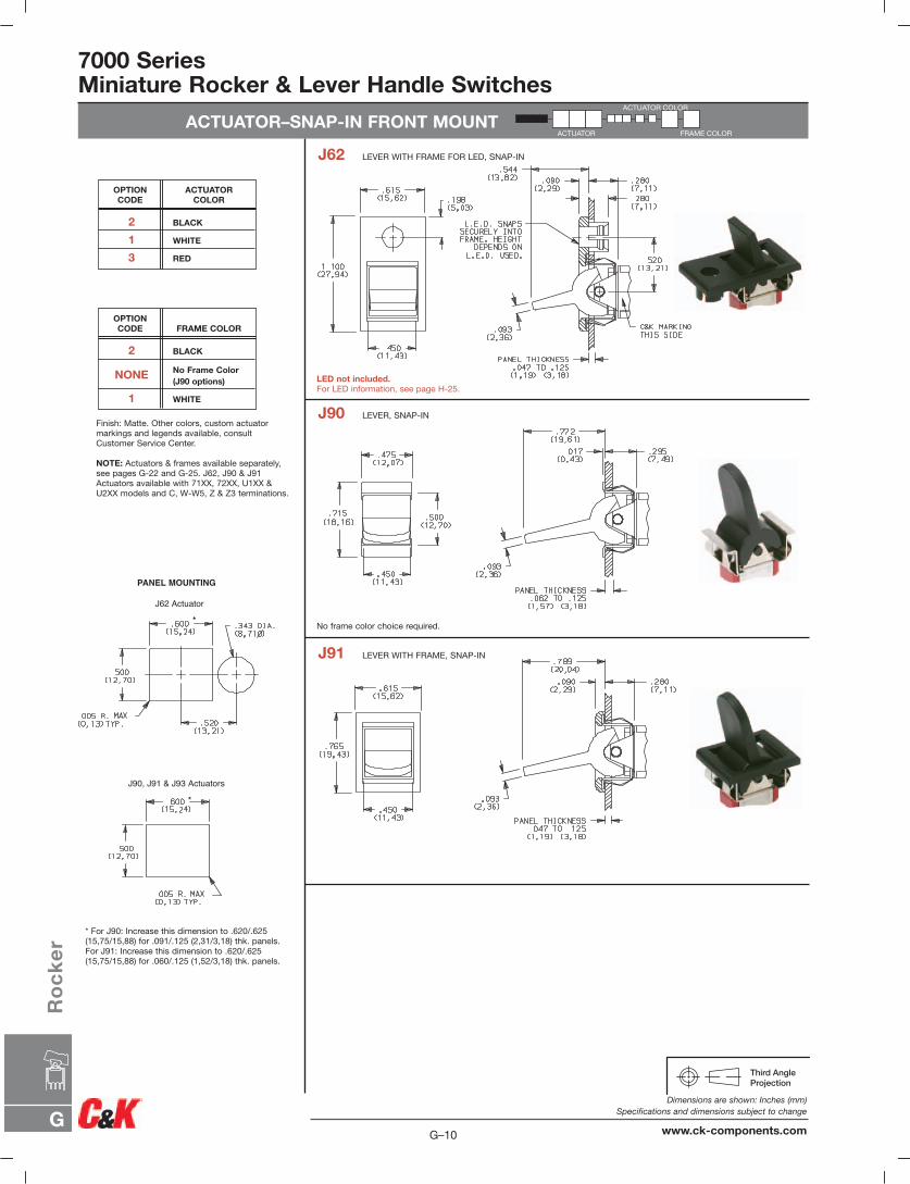
J62 LEVER WITH FRAME FOR LED, SNAP-IN
J90 LEVER, SNAP-IN
J91 LEVER WITH FRAME, SNAP-IN
Finish: Matte. Other colors, custom actuatormarkings and legends available, consultCustomer Service Center.
NOTE: Actuators & frames available separately,see pages G-22 and G-25. J62, J90 & J91Actuators available with 71XX, 72XX, U1XX &U2XX models and C, W-W5, Z & Z3 terminations.
* For J90: Increase this dimension to .620/.625(15,75/15,88) for .091/.125 (2,31/3,18) thk. panels.For J91: Increase this dimension to .620/.625(15,75/15,88) for .060/.125 (1,52/3,18) thk. panels.
2 BLACK
1 WHITE
3 RED
ACTUATORCOLOR
OPTION CODE
2 BLACK
NONE No Frame Color(J90 options)
1 WHITE
FRAME COLOROPTION CODE
No frame color choice required.
LED not included.For LED information, see page H-25.
ACTUATOR COLOR
FRAME COLORACTUATOR
7000 SeriesMiniature Rocker & Lever Handle Switches
ACTUATOR–REAR MOUNT
.313(7,95)
PANEL MOUNTING
J11 & J21 Actuators
J19 Actuator
J37 Actuator
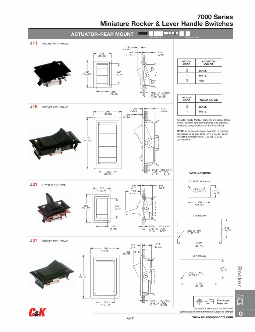
J11 ROCKER WITH FRAME
J19 ROCKER WITH FRAME
J21 LEVER WITH FRAME
J37 ROCKER WITH FRAME
Actuator finish: Matte. Frame finish: Gloss. Othercolors, custom actuator markings and legendsavailable, consult Customer Service Center.
NOTE: Actuators & frames available separately,see pages G-22 and G-25. J11, J19, J21 & J37Actuators available with C, W-W5, Z & Z3 terminations.
2 BLACK
1 WHITE
3 RED
ACTUATORCOLOR
OPTION CODE
2 BLACK
1 WHITE
FRAME COLOROPTION CODE
FRAME COLORACTUATOR
G
Ro
ck
er
G–11
Dimensions are shown: Inches (mm)Specifications and dimensions subject to change
www.ck-components.com
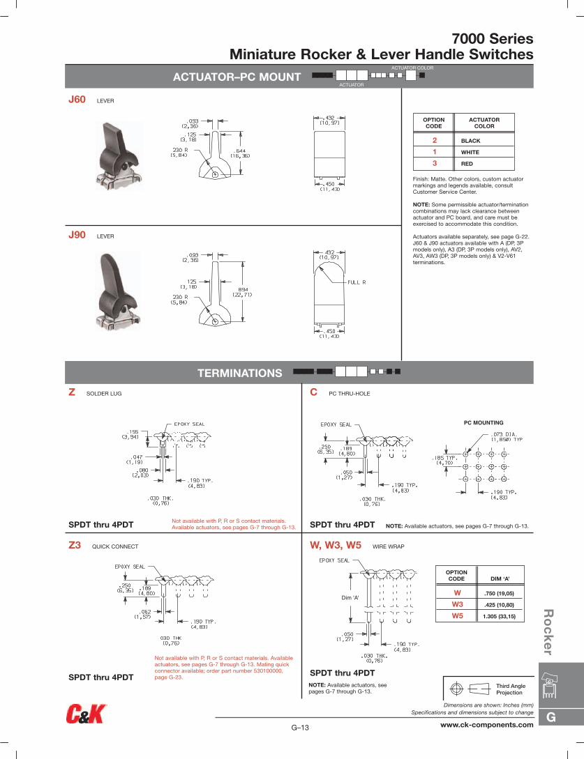
ACTUATOR–PC MOUNT
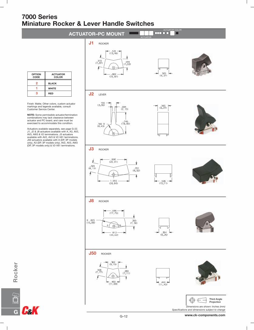
J1 ROCKER
J2 LEVER
J3 ROCKER
J8 ROCKER
J50 ROCKER
Finish: Matte. Other colors, custom actuatormarkings and legends available, consultCustomer Service Center.
NOTE: Some permissible actuator/terminationcombinations may lack clearance betweenactuator and PC board, and care must beexercised to accommodate this condition.
Actuators available separately, see page G-22.J1, J2 & J8 actuators available with A, A3, AV2,AV3, AW3 & V2 terminations. J3 actuatorsavailable with AV2, AV3 & V2-V61 terminations.J50 actuators available with A (DP, 3P modelsonly), A3 (DP, 3P models only), AV2, AV3, AW3(DP, 3P models only) & V2-V61 terminations.
2 BLACK
1 WHITE
3 RED
ACTUATORCOLOR
OPTION CODE
ACTUATOR COLOR
ACTUATOR
7000 SeriesMiniature Rocker & Lever Handle Switches
G–12
Dimensions are shown: Inches (mm)Specifications and dimensions subject to change
www.ck-components.comG
Ro
ck
er
7000 SeriesMiniature Rocker & Lever Handle Switches
ACTUATOR–PC MOUNT
TERMINATIONS
PC MOUNTING
Dim 'A'
SPDT thru 4PDT SPDT thru 4PDT
Z3 QUICK CONNECT W, W3, W5 WIRE WRAP
SPDT thru 4PDT Not available with P, R or S contact materials.Available actuators, see pages G-7 through G-13.
Not available with P, R or S contact materials. Availableactuators, see pages G-7 through G-13. Mating quickconnector available; order part number 530100000,page G-23.
NOTE: Available actuators, see pages G-7 through G-13.
NOTE: Available actuators, see pages G-7 through G-13.
Finish: Matte. Other colors, custom actuatormarkings and legends available, consultCustomer Service Center.
NOTE: Some permissible actuator/terminationcombinations may lack clearance betweenactuator and PC board, and care must beexercised to accommodate this condition.
Actuators available separately, see page G-22.J60 & J90 actuators available with A (DP, 3Pmodels only), A3 (DP, 3P models only), AV2,AV3, AW3 (DP, 3P models only) & V2-V61 terminations.
SPDT thru 4PDT
Z SOLDER LUG C PC THRU-HOLE
J90 LEVER
J60 LEVER
ACTUATOR COLOR
ACTUATOR
2 BLACK
1 WHITE
3 RED
ACTUATORCOLOR
OPTION CODE
W .750 (19,05)
W3 .425 (10,80)
W5 1.305 (33,15)
DIM ‘A’OPTION CODE
G
Ro
ck
er
G–13
Dimensions are shown: Inches (mm)Specifications and dimensions subject to change
www.ck-components.com
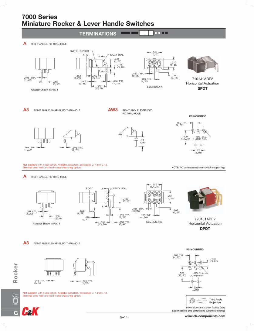
7000 SeriesMiniature Rocker & Lever Handle Switches
TERMINATIONS
PC MOUNTING
Actuator Shown In Pos. 1SECTION A-A
Actuator Shown In Pos. 1SECTION A-A
.14(3,6)
PC MOUNTING
A3 RIGHT ANGLE, SNAP-IN, PC THRU-HOLE
A RIGHT ANGLE, PC THRU-HOLE
A3 RIGHT ANGLE, SNAP-IN, PC THRU-HOLE AW3 RIGHT ANGLE, EXTENDED,PC THRU-HOLE
A RIGHT ANGLE, PC THRU-HOLE
Not available with I seal option. Available actuators, see pages G-7 and G-13.Terminal bend radii and lead-in manufacturing option. NOTE: PC pattern must clear switch support leg.
Not available with I seal option. Available actuators, see pages G-7 and G-13.Terminal bend radii and lead-in manufacturing option.
7101J1ABE2Horizontal Actuation
SPDT
7201J1ABE2Horizontal Actuation
DPDT
G–14
Dimensions are shown: Inches (mm)Specifications and dimensions subject to change
www.ck-components.comG
Ro
ck
er
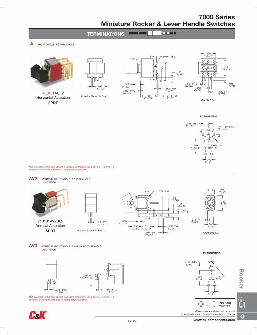
TERMINATIONS
7000 SeriesMiniature Rocker & Lever Handle Switches
Actuator Shown In Pos. 1SECTION A-A
PC MOUNTING
Actuator Shown In Pos. 1SECTION A-A
PC MOUNTING
AV3 VERTICAL RIGHT ANGLE, SNAP-IN, PC THRU-HOLE,.150" PITCH
AV2 VERTICAL RIGHT ANGLE, PC THRU-HOLE,.150" PITCH
A RIGHT ANGLE, PC THRU-HOLE
Not available with I seal option. Available actuators, see pages G-7 and G-13.Terminal bend radii and lead-in manufacturing option.
Not available with I seal option. Available actuators, see pages G-7 and G-13.Terminal bend radii and lead-in manufacturing option.
7301J1ABE2Horizontal Actuation
3PDT
7101J1AV2BE2Vertical Actuation
SPDT
G
Ro
ck
er
G–15
Dimensions are shown: Inches (mm)Specifications and dimensions subject to change
www.ck-components.com

7000 SeriesMiniature Rocker & Lever Handle Switches
TERMINATIONS
Actuator Shown In Pos. 1 SECTION A-A
Actuator Shown In Pos. 1 SECTION A-A
PC MOUNTING
PC MOUNTING
AV3 VERTICAL RIGHT ANGLE, SNAP-IN, PC THRU-HOLE,.150" PITCH
AV2 VERTICAL RIGHT ANGLE, PC THRU-HOLE,.150" PITCH
AV3 VERTICAL RIGHT ANGLE, SNAP-IN, PC THRU-HOLE,.150" PITCH
AV2 VERTICAL RIGHT ANGLE, PC THRU-HOLE,.150" PITCH
7201J1AV2BE2Vertical Actuation
DPDT
7301J1AV2BE2Vertical Actuation
3PDT
Not available with I seal option. Available actuators, see pages G-7 and G-13.Terminal bend radii and lead-in manufacturing option.
Not available with I seal option. Available actuators, see pages G-7 and G-13.Terminal bend radii and lead-in manufacturing option.
G–16
Dimensions are shown: Inches (mm)Specifications and dimensions subject to change
www.ck-components.comG
Ro
ck
er
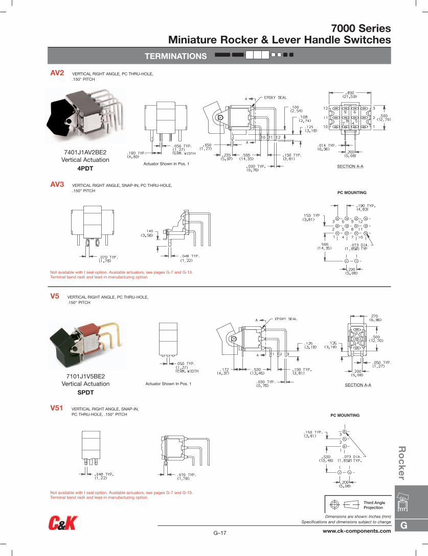
TERMINATIONS
7000 SeriesMiniature Rocker & Lever Handle Switches
Actuator Shown In Pos. 1 SECTION A-A
PC MOUNTING
PC MOUNTING
Actuator Shown In Pos. 1 SECTION A-A
V51 VERTICAL RIGHT ANGLE, SNAP-IN,PC THRU-HOLE, .150" PITCH
V5 VERTICAL RIGHT ANGLE, PC THRU-HOLE,.150" PITCH
AV3 VERTICAL RIGHT ANGLE, SNAP-IN, PC THRU-HOLE,.150" PITCH
AV2 VERTICAL RIGHT ANGLE, PC THRU-HOLE,.150" PITCH
Not available with I seal option. Available actuators, see pages G-7 and G-13.Terminal bend radii and lead-in manufacturing option.
Not available with I seal option. Available actuators, see pages G-7 and G-13.Terminal bend radii and lead-in manufacturing option.
7401J1AV2BE2Vertical Actuation
4PDT
7101J1V5BE2Vertical Actuation
SPDT
G
Ro
ck
er
G–17
Dimensions are shown: Inches (mm)Specifications and dimensions subject to change
www.ck-components.com
7000 SeriesMiniature Rocker & Lever Handle Switches
TERMINATIONS
Actuator Shown In Pos. 1
PC MOUNTING
PC MOUNTING
Actuator Shown In Pos. 1 SECTION A-A
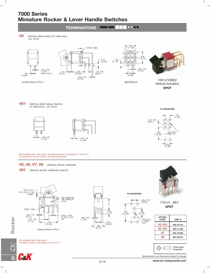
V61 VERTICAL MOUNT, V-BRACKET, SNAP-IN
V2, V6, V7, V8 VERTICAL MOUNT, V-BRACKET
V51 VERTICAL RIGHT ANGLE, SNAP-IN,PC THRU-HOLE, .150" PITCH
V5 VERTICAL RIGHT ANGLE, PC THRU-HOLE,.150" PITCH
Not available with I seal option. Available actuators, see pages G-7 and G-13.Terminal bend radii and lead-in manufacturing option.
Not available with I seal option. Available actuators, see pages G-7 and G-13.
7101J1__BE2SPDT
7201J1V5BE2Vertical Actuation
DPDT
V2, V21 .555 (14,10)
V6, V61 .460 (11,68)
V7 .630 (16,00)
V8 .953 (24,21)
DIM ‘A’OPTION CODE
G–18
Dimensions are shown: Inches (mm)Specifications and dimensions subject to change
www.ck-components.comG
Ro
ck
er
TERMINATIONS
7000 SeriesMiniature Rocker & Lever Handle Switches
Actuator Shown In Pos. 1
SNAP-IN
PC MOUNTING
Actuator Shown In Pos. 1
SNAP-IN
PC MOUNTING
Actuator Shown In Pos. 1
SNAP-IN
PC MOUNTING
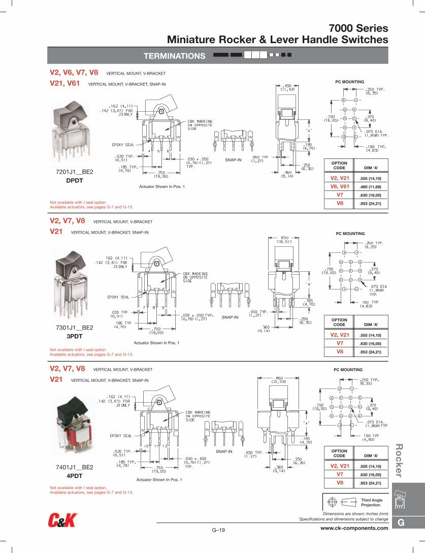
V2, V7, V8 VERTICAL MOUNT, V-BRACKET
V21 VERTICAL MOUNT, V-BRACKET, SNAP-IN
V2, V7, V8 VERTICAL MOUNT, V-BRACKET
V21, V61 VERTICAL MOUNT, V-BRACKET, SNAP-IN
V2, V6, V7, V8 VERTICAL MOUNT, V-BRACKET
Not available with I seal option.Available actuators, see pages G-7 and G-13.
Not available with I seal option.Available actuators, see pages G-7 and G-13.
Not available with I seal option.Available actuators, see pages G-7 and G-13.
V21 VERTICAL MOUNT, V-BRACKET, SNAP-IN
V2, V21 .555 (14,10)
V6, V61 .460 (11,68)
V7 .630 (16,00)
V8 .953 (24,21)
DIM ‘A’OPTION CODE
V2, V21 .555 (14,10)
V7 .630 (16,00)
V8 .953 (24,21)
DIM ‘A’OPTION CODE
V2, V21 .555 (14,10)
V7 .630 (16,00)
V8 .953 (24,21)
DIM ‘A’OPTION CODE
7201J1__BE2DPDT
7401J1__BE24PDT
7301J1__BE23PDT
G
Ro
ck
er
G–19
Dimensions are shown: Inches (mm)Specifications and dimensions subject to change
www.ck-components.com
7000 SeriesMiniature Rocker & Lever Handle Switches
TERMINATIONS
PC MOUNTING
Actuator Shown In Pos. 1
SNAP-IN
PC MOUNTING
Actuator Shown In Pos. 1
SNAP-IN
PC MOUNTING
Actuator Shown In Pos. 1
SNAP-IN
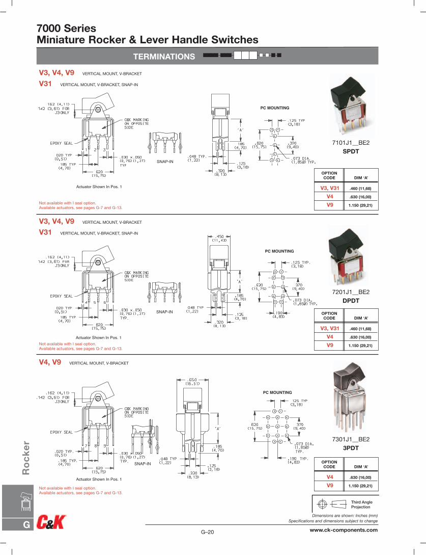
V4, V9 VERTICAL MOUNT, V-BRACKET
V31 VERTICAL MOUNT, V-BRACKET, SNAP-IN
V3, V4, V9 VERTICAL MOUNT, V-BRACKET
V31 VERTICAL MOUNT, V-BRACKET, SNAP-IN
V3, V4, V9 VERTICAL MOUNT, V-BRACKET
Not available with I seal option.Available actuators, see pages G-7 and G-13.
Not available with I seal option.Available actuators, see pages G-7 and G-13.
Not available with I seal option.Available actuators, see pages G-7 and G-13.
7101J1__BE2SPDT
7201J1__BE2DPDT
7301J1__BE23PDT
V3, V31 .460 (11,68)
V4 .630 (16,00)
V9 1.150 (29,21)
DIM ‘A’OPTION CODE
V3, V31 .460 (11,68)
V4 .630 (16,00)
V9 1.150 (29,21)
DIM ‘A’OPTION CODE
V4 .630 (16,00)
V9 1.150 (29,21)
DIM ‘A’OPTION CODE
G–20
Dimensions are shown: Inches (mm)Specifications and dimensions subject to change
www.ck-components.comG
Ro
ck
er
TERMINATIONS
7000 SeriesMiniature Rocker & Lever Handle Switches
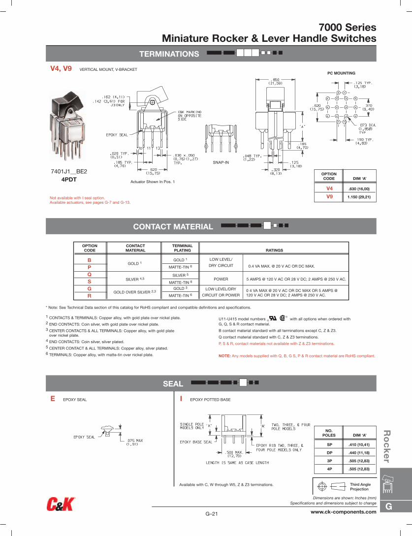
CONTACT MATERIAL
SEAL
'A'
Actuator Shown In Pos. 1
SNAP-IN
PC MOUNTING
* Note: See Technical Data section of this catalog for RoHS compliant and compatible definitions and specifications.
Available with C, W through W5, Z & Z3 terminations.
1 CONTACTS & TERMINALS: Copper alloy, with gold plate over nickel plate.2 END CONTACTS: Coin silver, with gold plate over nickel plate.3 CENTER CONTACTS & ALL TERMINALS: Copper alloy, with gold plate
over nickel plate.4 END CONTACTS: Coin silver, silver plated.5 CENTER CONTACT & ALL TERMINALS: Copper alloy, silver plated.6 TERMINALS: Copper alloy, with matte-tin over nickel plate.
U11-U415 model numbers with all options when ordered with G, Q, S & R contact material.
B contact material standard with all terminations except C, Z & Z3.
Q contact material standard with C, Z & Z3 terminations.
P, S & R, contact materials not available with Z & Z3 terminations.
NOTE: Any models supplied with Q, B, G S, P & R contact material are RoHS compliant.
V4 .630 (16,00)
V9 1.150 (29,21)
DIM ‘A’OPTION CODE
SP .410 (10,41)
DP .440 (11,18)
3P .505 (12,83)
4P .505 (12,83)
DIM ‘A’NO.
POLES
V4, V9 VERTICAL MOUNT, V-BRACKET
7401J1__BE24PDT
E EPOXY SEAL I EPOXY POTTED BASE
Not available with I seal option.Available actuators, see pages G-7 and G-13.
OPTION CODE
CONTACT MATERIAL
TERMINALPLATING RATINGS
SILVER 5
MATTE-TIN 6
GOLD 1
SILVER 4,5
GOLD OVER SILVER 2,3GOLD 3
MATTE-TIN 6
GOLD 1
MATTE-TIN 6
LOW LEVEL/
DRY CIRCUIT
POWER
LOW LEVEL/DRY
CIRCUIT OR POWER
0.4 VA MAX. @ 20 V AC OR DC MAX.
5 AMPS @ 120 V AC OR 28 V DC; 2 AMPS @ 250 V AC.
0 4 VA MAX @ 20 V AC OR DC MAX OR 5 AMPS @ 120 V AC OR 28 V DC; 2 AMPS @ 250 V AC.
BPQSGR
G
Ro
ck
er
G–21
Dimensions are shown: Inches (mm)Specifications and dimensions subject to change
www.ck-components.com
7000 SeriesMiniature Rocker & Lever Handle Switches
AVAILABLE HARDWARE
TYPICAL ASSEMBLYSCREW
PANEL THICKNESS
STAND-OFF
LOCKWASHERNUT
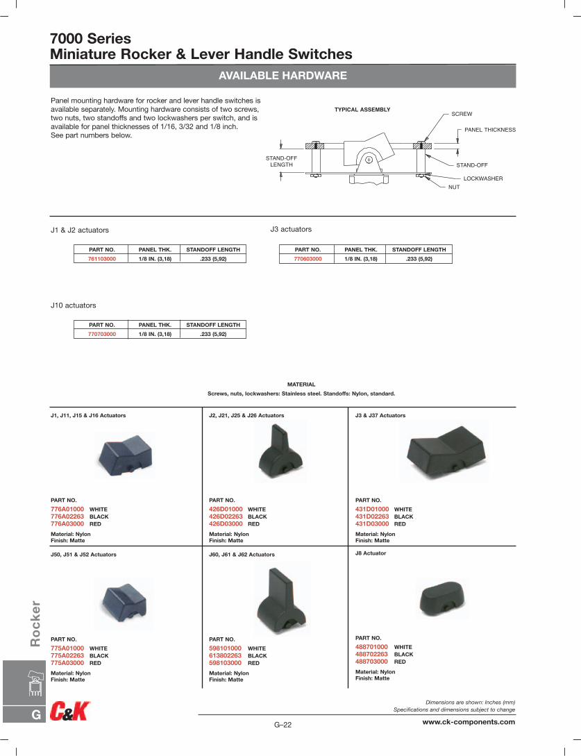
STAND-OFFLENGTH
Panel mounting hardware for rocker and lever handle switches isavailable separately. Mounting hardware consists of two screws,two nuts, two standoffs and two lockwashers per switch, and isavailable for panel thicknesses of 1/16, 3/32 and 1/8 inch. See part numbers below.
J1 & J2 actuators
J10 actuators
J3 actuators
PART NO. PANEL THK. STANDOFF LENGTH
761103000 1/8 IN. (3,18) .233 (5,92)
PART NO. PANEL THK. STANDOFF LENGTH
770703000 1/8 IN. (3,18) .233 (5,92)
PART NO. PANEL THK. STANDOFF LENGTH
770603000 1/8 IN. (3,18) .233 (5,92)
MATERIAL
Screws, nuts, lockwashers: Stainless steel. Standoffs: Nylon, standard.
J1, J11, J15 & J16 Actuators
PART NO.
776A01000 WHITE776A02263 BLACK776A03000 RED
Material: NylonFinish: Matte
J50, J51 & J52 Actuators
PART NO.
775A01000 WHITE775A02263 BLACK775A03000 RED
Material: NylonFinish: Matte
J60, J61 & J62 Actuators
PART NO.
598101000 WHITE613802263 BLACK598103000 RED
Material: NylonFinish: Matte
J8 Actuator
PART NO.
488701000 WHITE488702263 BLACK488703000 RED
Material: NylonFinish: Matte
J2, J21, J25 & J26 Actuators
PART NO.
426D01000 WHITE426D02263 BLACK426D03000 RED
Material: NylonFinish: Matte
J3 & J37 Actuators
PART NO.
431D01000 WHITE431D02263 BLACK431D03000 RED
Material: NylonFinish: Matte
G–22
Dimensions are shown: Inches (mm)Specifications and dimensions subject to change
www.ck-components.comG
Ro
ck
er
AVAILABLE HARDWARE
7000 SeriesMiniature Rocker & Lever Handle Switches
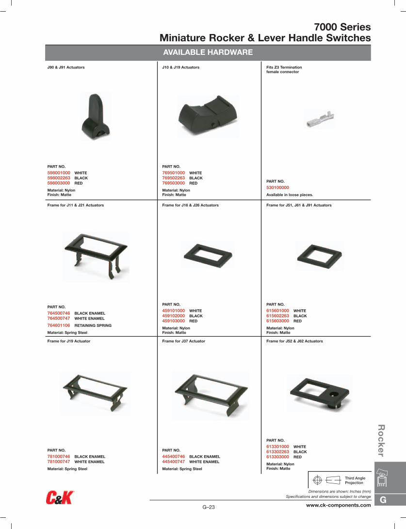
J90 & J91 Actuators
PART NO.
598001000 WHITE598002263 BLACK598003000 RED
Material: NylonFinish: Matte
J10 & J19 Actuators
PART NO.
769501000 WHITE769502263 BLACK769503000 RED
Material: NylonFinish: Matte
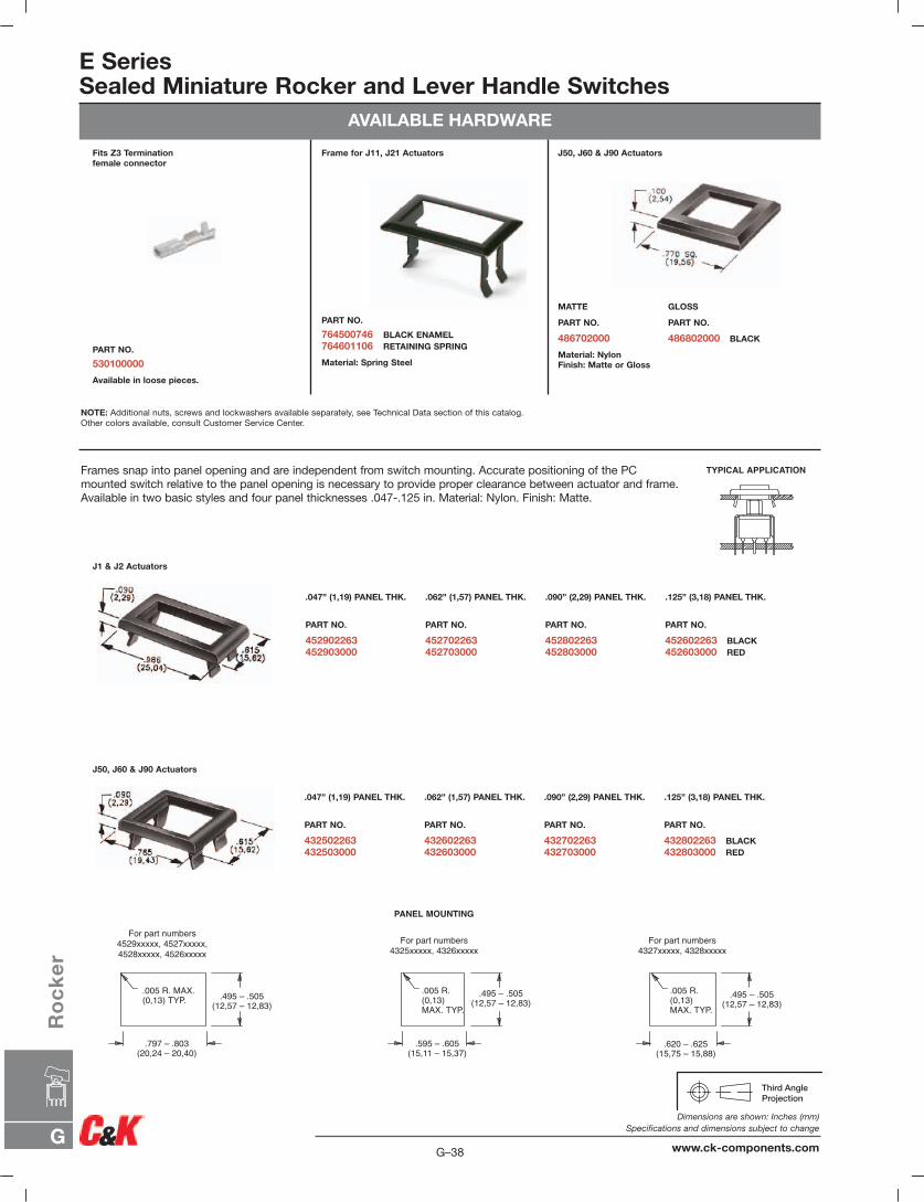
Fits Z3 Terminationfemale connector
PART NO.
530100000
Available in loose pieces.
Frame for J11 & J21 Actuators
PART NO.
764500746 BLACK ENAMEL764500747 WHITE ENAMEL
764601106 RETAINING SPRING
Material: Spring Steel
Frame for J19 Actuator
PART NO.
781000746 BLACK ENAMEL781000747 WHITE ENAMEL
Material: Spring Steel
Frame for J37 Actuator
PART NO.
445400746 BLACK ENAMEL445400747 WHITE ENAMEL
Material: Spring Steel
Frame for J52 & J62 Actuators
PART NO.
613301000 WHITE613302263 BLACK613303000 RED
Material: NylonFinish: Matte
Frame for J16 & J26 Actuators
PART NO.
459101000 WHITE459102000 BLACK459103000 RED
Material: NylonFinish: Matte
Frame for J51, J61 & J91 Actuators
PART NO.
615601000 WHITE615602263 BLACK615603000 RED
Material: NylonFinish: Matte
G
Ro
ck
er
G–23
Dimensions are shown: Inches (mm)Specifications and dimensions subject to change
www.ck-components.com
7000 SeriesMiniature Rocker & Lever Handle Switches
AVAILABLE HARDWARE
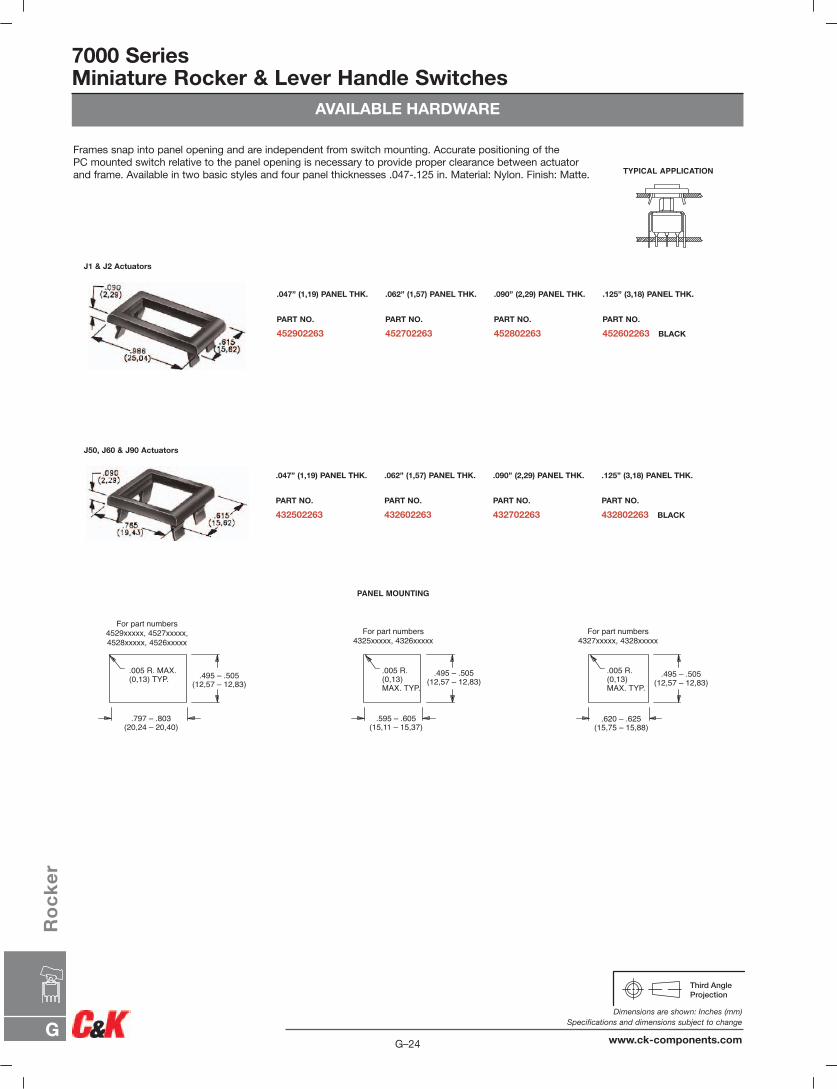
.495 – .505(12,57 – 12,83)
.797 – .803(20,24 – 20,40)
.005 R. MAX.(0,13) TYP.
.495 – .505(12,57 – 12,83)
.595 – .605(15,11 – 15,37)
.005 R.(0,13)MAX. TYP.
.495 – .505(12,57 – 12,83)
.620 – .625(15,75 – 15,88)
.005 R.(0,13)MAX. TYP.
PANEL MOUNTING
For part numbers4529xxxxx, 4527xxxxx,4528xxxxx, 4526xxxxx
For part numbers4325xxxxx, 4326xxxxx
For part numbers4327xxxxx, 4328xxxxx
TYPICAL APPLICATION
J1 & J2 Actuators
J50, J60 & J90 Actuators
.125” (3,18) PANEL THK.
PART NO.
452602263 BLACK
.047” (1,19) PANEL THK.
PART NO.
452902263
.062” (1,57) PANEL THK.
PART NO.
452702263
.090” (2,29) PANEL THK.
PART NO.
452802263
.125” (3,18) PANEL THK.
PART NO.
432802263 BLACK
.047” (1,19) PANEL THK.
PART NO.
432502263
.062” (1,57) PANEL THK.
PART NO.
432602263
.090” (2,29) PANEL THK.
PART NO.
432702263
Frames snap into panel opening and are independent from switch mounting. Accurate positioning of thePC mounted switch relative to the panel opening is necessary to provide proper clearance between actuatorand frame. Available in two basic styles and four panel thicknesses .047-.125 in. Material: Nylon. Finish: Matte.
G–24
Dimensions are shown: Inches (mm)Specifications and dimensions subject to change
www.ck-components.comG
Ro
ck
er
G
Ro
ck
er
G–25
Dimensions are shown: Inches (mm)Specifications and dimensions subject to change
www.ck-components.com
7000 SeriesMiniature Rocker & Lever Handle SwitchesAVAILABLE HARDWARE
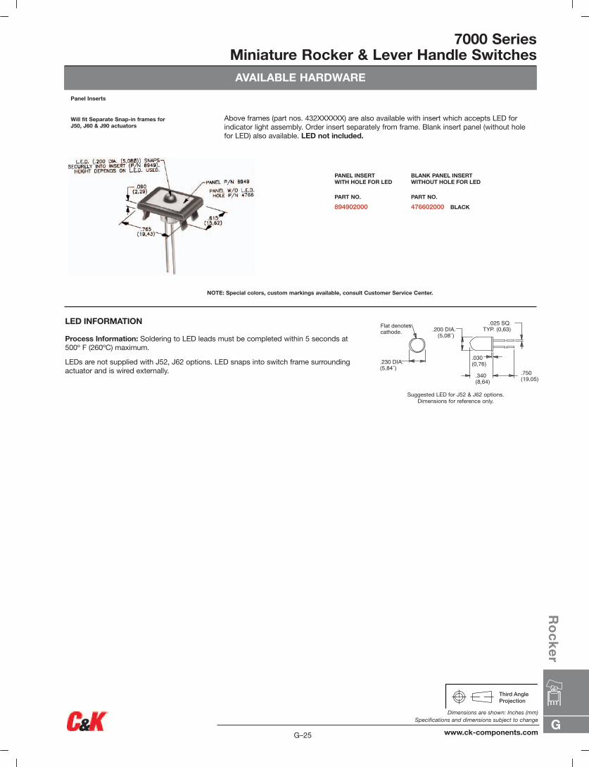
.030(0,76)
.200 DIA.(5,08˘)
.025 SQ.TYP. (0,63)
.750(19,05).340
(8,64)
.230 DIA.(5,84˘)
Flat denotescathode.
Above frames (part nos. 432XXXXXX) are also available with insert which accepts LED for indicator light assembly. Order insert separately from frame. Blank insert panel (without holefor LED) also available. LED not included.
LED INFORMATION
Process Information: Soldering to LED leads must be completed within 5 seconds at500º F (260ºC) maximum.
LEDs are not supplied with J52, J62 options. LED snaps into switch frame surrounding actuator and is wired externally.
Panel Inserts
Will fit Separate Snap-in frames forJ50, J60 & J90 actuators
NOTE: Special colors, custom markings available, consult Customer Service Center.
Suggested LED for J52 & J62 options.Dimensions for reference only.
BLANK PANEL INSERTWITHOUT HOLE FOR LED
PART NO.
476602000 BLACK
PANEL INSERTWITH HOLE FOR LED
PART NO.
894902000
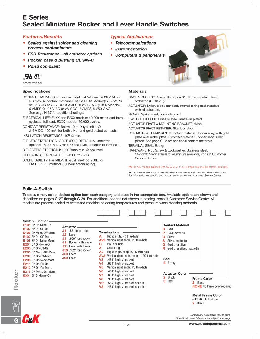
E SeriesSealed Miniature Rocker and Lever Handle Switches
Models Available
Features/Benefits• Sealed against solder and cleaning
process contaminants
• ESD Resistance—all actuator options
• Rocker, case & bushing UL 94V-0
• RoHS compliant
Typical Applications• Telecommunications
• Instrumentation
• Computers & peripherals
SpecificationsCONTACT RATING: B contact material: 0.4 VA max. @ 20 V AC or
DC max. Q contact material (E1XX & E2XX Models): 7.5 AMPS@125 V AC or 28 V DC; 3 AMPS @ 250 V AC. (E3XX Models):5 AMPS @ 125 V AC or 28 V DC; 2 AMPS @ 250 V AC.See page H-37 for additional ratings.
ELECTRICAL LIFE: E1XX and E2XX models: 40,000 make-and-breakcycles at full load. E3XX models: 30,000 cycles.
CONTACT RESISTANCE: Below 10 m Ω typ. initial @2-4 V DC, 100 mA, for both silver and gold plated contacts.
INSULATION RESISTANCE: 109 Ω min.
ELECTROSTATIC DISCHARGE (ESD) OPTION: All actuatoroptions: 15,000 V DC max. @ sea level, actuator to terminals.
DIELECTRIC STRENGTH: 1000 Vrms min. @ sea level.
OPERATING TEMPERATURE: –30ºC to 85ºC.
SOLDERABILITY: Per MIL-STD-202F method 208D, orEIA RS-186E method 9 (1 hour steam aging).
MaterialsCASE & BUSHING: Glass filled nylon 6/6, flame retardant, heat
stabilized (UL 94V-0).ACTUATOR: Nylon, black standard, internal o-ring seal standard
with all actuators.FRAME: Spring steel, black standard.SWITCH SUPPORT: Brass or steel, matte-tin plated.ACTUATOR PIVOT & MOUNTING BRACKET: Nylon.ACTUATOR PIVOT RETAINER: Stainless steel.CONTACTS & TERMINALS: B contact material: Copper alloy, with gold
plate over nickel plate. Q contact material: Copper alloy, silverplated. See page G-37 for additional contact materials.
TERMINAL SEAL: Epoxy.HARDWARE: Nut, Screw & Lockwasher: Stainless steel.
Standoff: Nylon standard, aluminum available, consult CustomerService Center.
NOTE: Any models supplied with Q, B, G, S, P & R contact material are RoHS compliant.
NOTE: Specifications and materials listed above are for switches with standard options.For information on specific and custom switches, consult Customer Service Center.
Build-A-SwitchTo order, simply select desired option from each category and place in the appropriate box. Available options are shown anddescribed on pages G-27 through G-39. For additional options not shown in catalog, consult Customer Service Center. All models are process sealed to withstand machine soldering temperatures and pressure wash cleaning methods.
Switch FunctionE101 SP On-None-OnE103 SP On-Off-OnE105 SP Mom.-Off-Mom.E107 SP On-Off-Mom.E108 SP On-None-Mom.E201 DP On-None-OnE203 DP On-Off-OnE205 DP Mom.-Off-Mom.E207 DP On-Off-Mom.E208 DP On-None-Mom.E211 DP On-On-OnE213 DP On-On-Mom.E215 DP Mom.-On-Mom.E301 3P On-None-On
ActuatorJ1 .531 long rockerJ2 LeverJ3 .906" long rockerJ11 Rocker with frameJ21 Lever with frameJ50 .362" long rockerJ60 LeverJ90 Lever
TerminationsA Right angle, PC thru-holeAV2 Vertical right angle, PC thru-holeC PC Thru-holeZ Solder lugA3 Right angle, snap-in, PC thru-holeAV3 Vertical right angle, snap-in, PC thru-holeV3 .460" high, V-bracketV4 .630" high, V-bracketV5 Vertical right angle, PC thru-holeV6 .460" high, V-bracketV7 .630" high, V-bracketV8 .953" high, V-bracketV21 .555" high, V-bracket, snap-inV31 .460" high, V-bracket, snap-in
Contact MaterialB GoldP Gold, matte tinQ SilverS Silver, matte-tinG Gold over silverR Gold over silver, matte-tin
SealE Epoxy
Actuator Color2 Black3 Red
Frame Color2 BlackNONE No frame color required
Metal Frame Color(J11, J21 Actuators)2 Black
G–26
Dimensions are shown: Inches (mm)Specifications and dimensions subject to change
www.ck-components.comG
Ro
ck
er
DPDT
2-1,5-4
N/A
OPEN
N/A
2-3,5-4
2-3,5-6
ON NONE ON
ON OFF ON
MOM. OFF MOM.
ON OFF MOM.
ON NONE MOM.
ON ON ON
ON ON MOM.
MOM. ON MOM.
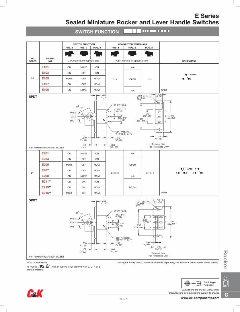
E201
E203
E205
E207
E208
E211**
E213**
E215**
DP
SPDT
2-1
N/A
OPEN
N/A
2-3
ON NONE ON
ON OFF ON
MOM. OFF MOM.
ON OFF MOM.
ON NONE MOM.
E101
E103
E105
E107
E108
SP
SCHEMATIC
CONNECTED TERMINALS
POS. 1 POS. 2 POS. 3
SWITCH FUNCTION
POS. 1 POS. 2 POS. 3
MODEL NO.
NO.POLES
E SeriesSealed Miniature Rocker and Lever Handle Switches
SWITCH FUNCTION
DPDT
SPDT
Part number shown: E101J1ZBE2
Part number shown: E201J1ZBE2
** Wiring for 3-way switch, Hardware available seperately, see Technical Data section of this catalog.MOM. = Momentary
All models with all options when ordered with G, Q, R or S contact material.
Terminal Nos.For Reference Only
Terminal Nos.For Reference Only
C&K marking on opposite sideC&K marking on opposite side
G
Ro
ck
er
G–27
Dimensions are shown: Inches (mm)Specifications and dimensions subject to change
www.ck-components.com
G–28
Dimensions are shown: Inches (mm)Specifications and dimensions subject to change
www.ck-components.comG
Ro
ck
er
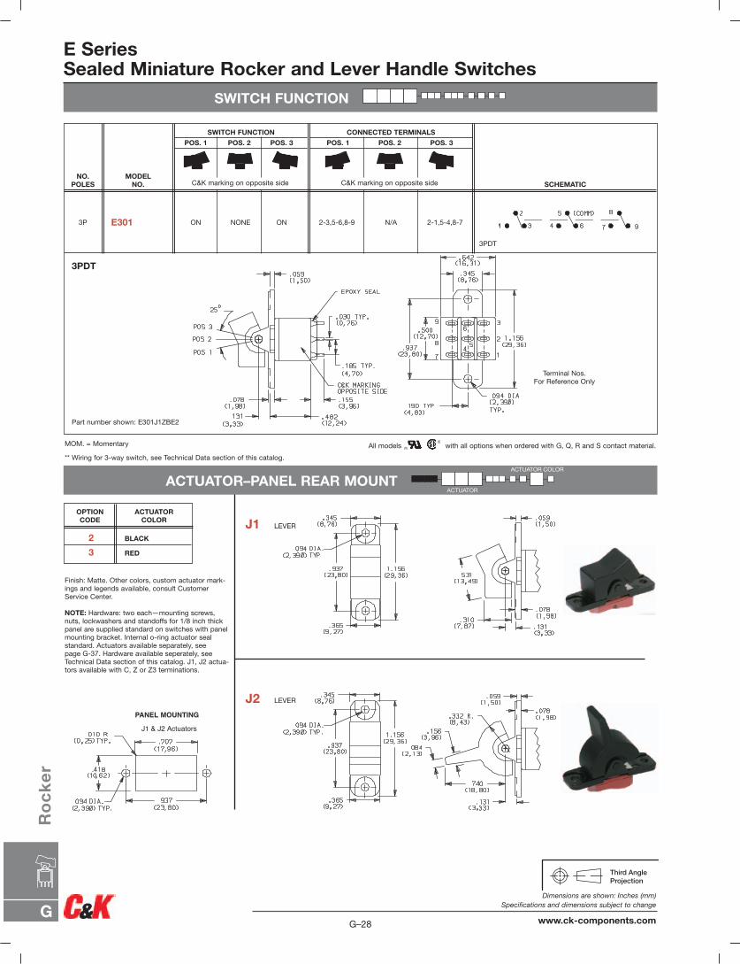
E SeriesSealed Miniature Rocker and Lever Handle Switches
SWITCH FUNCTION
ACTUATOR–PANEL REAR MOUNT
PANEL MOUNTING
J1 & J2 Actuators
3PDT
2-1,5-4,8-7N/A2-3,5-6,8-9ON NONE ONE301 3P
SCHEMATIC
CONNECTED TERMINALS
POS. 1 POS. 2 POS. 3
SWITCH FUNCTION
POS. 1 POS. 2 POS. 3
MODEL NO.
NO.POLES
3PDT
C&K marking on opposite sideC&K marking on opposite side
Part number shown: E301J1ZBE2
All models with all options when ordered with G, Q, R and S contact material.MOM. = Momentary
** Wiring for 3-way switch, see Technical Data section of this catalog.
Terminal Nos.For Reference Only
Finish: Matte. Other colors, custom actuator mark-ings and legends available, consult CustomerService Center.
NOTE: Hardware: two each—mounting screws,nuts, lockwashers and standoffs for 1/8 inch thickpanel are supplied standard on switches with panelmounting bracket. Internal o-ring actuator seal standard. Actuators available separately, see page G-37. Hardware available seperately, seeTechnical Data section of this catalog. J1, J2 actua-tors available with C, Z or Z3 terminations.
2 BLACK
3 RED
ACTUATORCOLOR
OPTION CODE J1 LEVER
J2 LEVER
ACTUATOR COLOR
ACTUATOR

G
Ro
ck
er
G–29
Dimensions are shown: Inches (mm)Specifications and dimensions subject to change
www.ck-components.com
E SeriesSealed Miniature Rocker and Lever Handle Switches
ACTUATOR–REAR MOUNT
PANEL MOUNTING
Actuator finish: Matte, frame finish: gloss.Other colors, custom actuator markings and legends available, consult CustomerService Center.
NOTE: Internal o-ring actuator seal standard.Actuators & frames available separately, seepage G-37. Hardware available seperately, seeTechnical Data section of this catalog. N. J11& J21 actuators available with C, Z & Z3 ter-minations.
2 BLACK
FRAME COLOROPTION CODE
ACTUATOR–PC MOUNT
Finish: Matte. Other colors, custom actuatormarkings and legends available, consultCustomer Service Center.
NOTE: Hardware: two each—mountingscrews, nuts, lockwashers and standoffs for1/8 inch thick panel are supplied standard onswitches with panel mounting bracket. Internalo-ring actuator seal standard. Actuators available separately, see page G-37. Hardwareavailable seperately, see Technical Data sec-tion of this catalog. J1, J2 actuators availablewith A, A3, AV2, AV3, V2-V61 terminations.
ACTUATOR COLOR
ACTUATOR
FRAME COLORACTUATOR
ACTUATOR COLOR
J11 ROCKER WITH FRAME
J21 LEVER WITH FRAME
J1 ROCKER
J2 LEVER
NOTE: This option has reduced anti-static capability.
NOTE: This option has reduced anti-static capability.
2 BLACK
3 RED
ACTUATORCOLOR
OPTION CODE
2 BLACK
3 RED
ACTUATORCOLOR
OPTION CODE
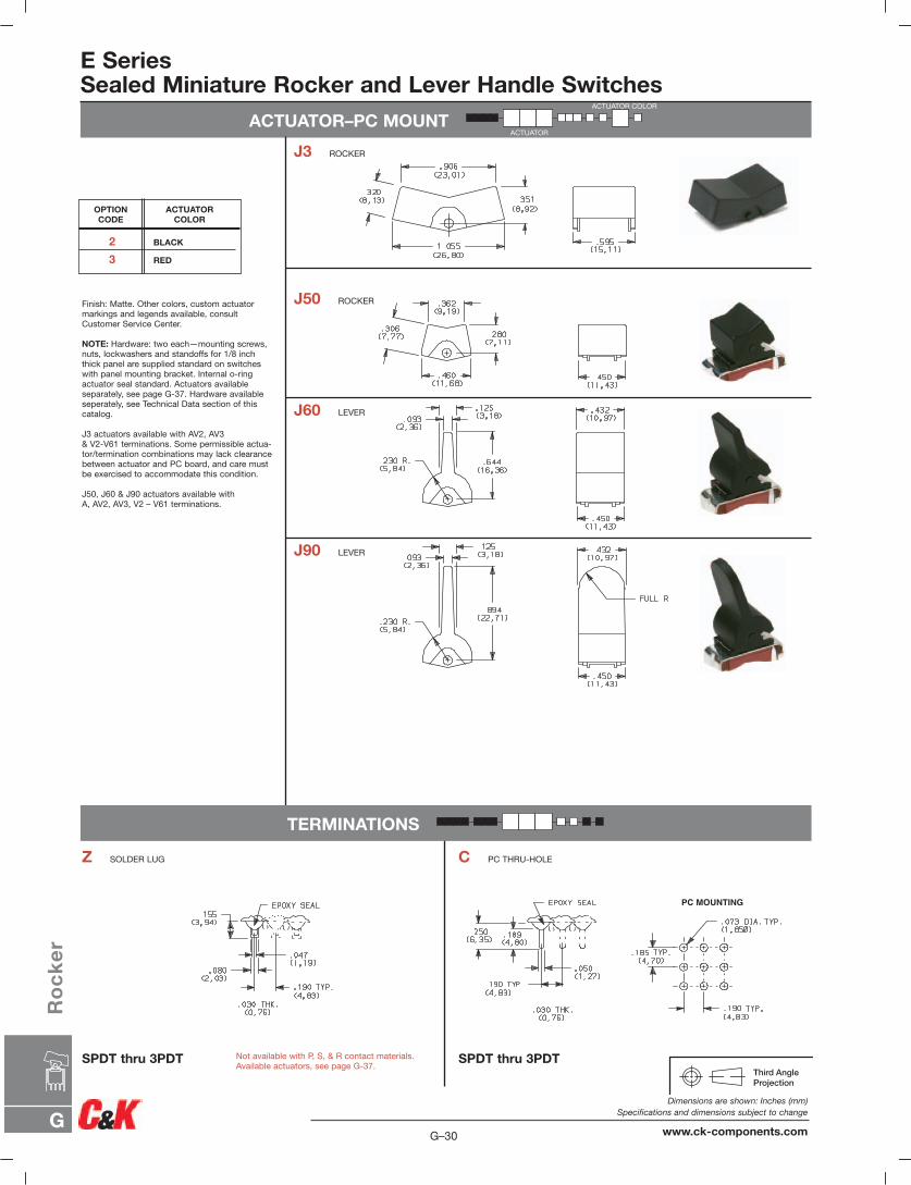
E SeriesSealed Miniature Rocker and Lever Handle Switches
ACTUATOR–PC MOUNT
PC MOUNTING
Finish: Matte. Other colors, custom actuatormarkings and legends available, consultCustomer Service Center.
NOTE: Hardware: two each—mounting screws,nuts, lockwashers and standoffs for 1/8 inchthick panel are supplied standard on switcheswith panel mounting bracket. Internal o-ringactuator seal standard. Actuators available separately, see page G-37. Hardware availableseperately, see Technical Data section of thiscatalog.
J3 actuators available with AV2, AV3 & V2-V61 terminations. Some permissible actua-tor/termination combinations may lack clearancebetween actuator and PC board, and care mustbe exercised to accommodate this condition.
J50, J60 & J90 actuators available with A, AV2, AV3, V2 – V61 terminations.
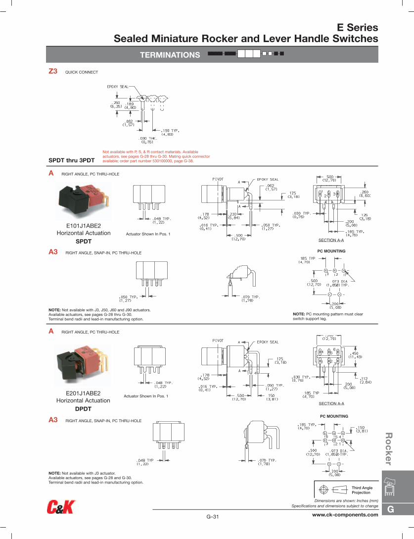
TERMINATIONS
Z SOLDER LUG C PC THRU-HOLE
SPDT thru 3PDT SPDT thru 3PDTNot available with P, S, & R contact materials.Available actuators, see page G-37.
ACTUATOR COLOR
ACTUATOR
J3 ROCKER
J50 ROCKER
J60 LEVER
J90 LEVER
2 BLACK
3 RED
ACTUATORCOLOR
OPTION CODE
G–30
Dimensions are shown: Inches (mm)Specifications and dimensions subject to change
www.ck-components.comG
Ro
ck
er
E SeriesSealed Miniature Rocker and Lever Handle Switches
TERMINATIONS
PC MOUNTING
PC MOUNTING
Actuator Shown In Pos. 1
SECTION A-A
Actuator Shown In Pos. 1SECTION A-A
A3 RIGHT ANGLE, SNAP-IN, PC THRU-HOLE
A RIGHT ANGLE, PC THRU-HOLE
A3 RIGHT ANGLE, SNAP-IN, PC THRU-HOLE
A RIGHT ANGLE, PC THRU-HOLE
SPDT thru 3PDT
Z3 QUICK CONNECT
NOTE: Not available with J3 actuator.Available actuators, see pages G-28 and G-30.Terminal bend radii and lead-in manufacturing option.
NOTE: Not available with J3, J50, J60 and J90 actuators.Available actuators, see pages G-28 thru G-30.Terminal bend radii and lead-in manufacturing option.
Not available with P, S, & R contact materials. Availableactuators, see pages G-28 thru G-30. Mating quick connectoravailable; order part number 530100000, page G-38.
NOTE: PC mounting pattern must clearswitch support leg.
E101J1ABE2Horizontal Actuation
SPDT
E201J1ABE2Horizontal Actuation
DPDT
G
Ro
ck
er
G–31
Dimensions are shown: Inches (mm)Specifications and dimensions subject to change
www.ck-components.com

E SeriesSealed Miniature Rocker and Lever Handle Switches
TERMINATIONS
Actuator Shown In Pos. 1
SECTION A-A
PC MOUNTING
Actuator Shown In Pos. 1 SECTION A-A
PC MOUNTING
AV3 VERTICAL RIGHT ANGLE, SNAP-IN, PC THRU-HOLE,.150" PITCH
AV2 VERTICAL RIGHT ANGLE, PC THRU-HOLE,.150" PITCH
A RIGHT ANGLE, PC THRU-HOLE
NOTE: Terminal bend radii and lead-in manufacturing option.Available actuators, see pages G-28 and G-30.
NOTE: Terminal bend radii and lead-in manufacturing option.Available actuators, see pages G-28 and G-30.
E301J1ABE2Horizontal Actuation
3PDT
E101J1AV2BE2Vertical Actuation
SPDT
G–32
Dimensions are shown: Inches (mm)Specifications and dimensions subject to change
www.ck-components.comG
Ro
ck
er
E SeriesSealed Miniature Rocker and Lever Handle Switches
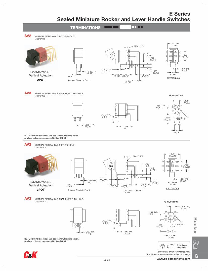
TERMINATIONS
SECTION A-AActuator Shown In Pos. 1
Actuator Shown In Pos. 1SECTION A-A
PC MOUNTING
PC MOUNTING
AV3 VERTICAL RIGHT ANGLE, SNAP-IN, PC THRU-HOLE,.150" PITCH
AV2 VERTICAL RIGHT ANGLE, PC THRU-HOLE,.150" PITCH
AV3 VERTICAL RIGHT ANGLE, SNAP-IN, PC THRU-HOLE,.150" PITCH
AV2 VERTICAL RIGHT ANGLE, PC THRU-HOLE,.150" PITCH
NOTE: Terminal bend radii and lead-in manufacturing option.Available actuators, see pages G-28 and G-30.
NOTE: Terminal bend radii and lead-in manufacturing option.Available actuators, see pages G-28 and G-30.
E301J1AV2BE2Vertical Actuation
3PDT
E201J1AV2BE2Vertical Actuation
DPDT
G
Ro
ck
er
G–33
Dimensions are shown: Inches (mm)Specifications and dimensions subject to change
www.ck-components.com

E SeriesSealed Miniature Rocker and Lever Handle Switches
TERMINATIONS
SECTION A-A
Actuator Shown In Pos. 1
PC MOUNTING
Actuator Shown In Pos. 1 SECTION A-A
PC MOUNTING
V5 VERTICAL RIGHT ANGLE, PC THRU-HOLE,.150" PITCH
NOTE: Terminal bend radii and lead-in manufacturing option.Available actuators, see pages G-28 and G-30.
NOTE: Terminal bend radii and lead-in manufacturing option.Available actuators, see pages G-28 and G-30.
V5 VERTICAL RIGHT ANGLE, PC THRU-HOLE,.150" PITCH
E101J1V5BE2Vertical Actuation
SPDT
E201J1V5BE2Vertical Actuation
DPDT
G–34
Dimensions are shown: Inches (mm)Specifications and dimensions subject to change
www.ck-components.comG
Ro
ck
er
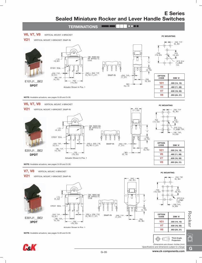
E SeriesSealed Miniature Rocker and Lever Handle Switches
TERMINATIONS
PC MOUNTING
PC MOUNTING
PC MOUNTING
V21 VERTICAL MOUNT, V-BRACKET, SNAP-IN
V7, V8 VERTICAL MOUNT, V-BRACKET
V21 VERTICAL MOUNT, V-BRACKET, SNAP-IN
V6, V7, V8 VERTICAL MOUNT, V-BRACKET
V21 VERTICAL MOUNT, V-BRACKET, SNAP-IN
V6, V7, V8 VERTICAL MOUNT, V-BRACKET
NOTE: Available actuators, see pages G-28 and G-30.
NOTE: Available actuators, see pages G-28 and G-30.
NOTE: Available actuators, see pages G-28 and G-30.
V21 .555 (14, 10)
V6 .460 (11, 68)
V7 .630 (16, 00)
V8 .953 (24, 21)
DIM ‘A’OPTION CODE
V21 .555 (14, 10)
V6 .460 (11, 68)
V7 .630 (16, 00)
V8 .953 (24, 21)
DIM ‘A’OPTION CODE
V21 .555 (14, 10)
V7 .630 (16, 00)
V8 .953 (24, 21)
DIM ‘A’OPTION CODE
E101J1__BE2SPDT
E201J1__BE2DPDT
E301J1__BE23PDT
G
Ro
ck
er
G–35
Dimensions are shown: Inches (mm)Specifications and dimensions subject to change
www.ck-components.com

G–36
Dimensions are shown: Inches (mm)Specifications and dimensions subject to change
www.ck-components.comG
Ro
ck
er
E SeriesSealed Miniature Rocker and Lever Handle Switches
TERMINATIONS
PC MOUNTING
PC MOUNTING
PC MOUNTING
V31 VERTICAL MOUNT, V-BRACKET, SNAP-IN
V3, V4 VERTICAL MOUNT, V-BRACKET
VERTICAL MOUNT, V-BRACKET, SNAP-IN
V4 VERTICAL MOUNT, V-BRACKET
V31 VERTICAL MOUNT, V-BRACKET, SNAP-IN
V3, V4 VERTICAL MOUNT, V-BRACKET
NOTE: Available actuators, see pages G-28 and G-30.
NOTE: Available actuators, see pages G-28 and G-30.
NOTE: Available actuators, see pages G-28 and G-30.
V3, V31 .460 (11,68)
V4 .630 (16,00)
DIM ‘A’OPTION CODE
V41 .630 (16,00)
DIM ‘A’OPTION CODE
V3, V31 .460 (11,68)
V4 .630 (16,00)
DIM ‘A’OPTION CODE
E101J1__BE2SPDT
E201J1__BE2DPDT
E301J1__BE23PDT
G
Ro
ck
er
G–37
Dimensions are shown: Inches (mm)Specifications and dimensions subject to change
www.ck-components.com
E SeriesSealed Miniature Rocker and Lever Handle Switches
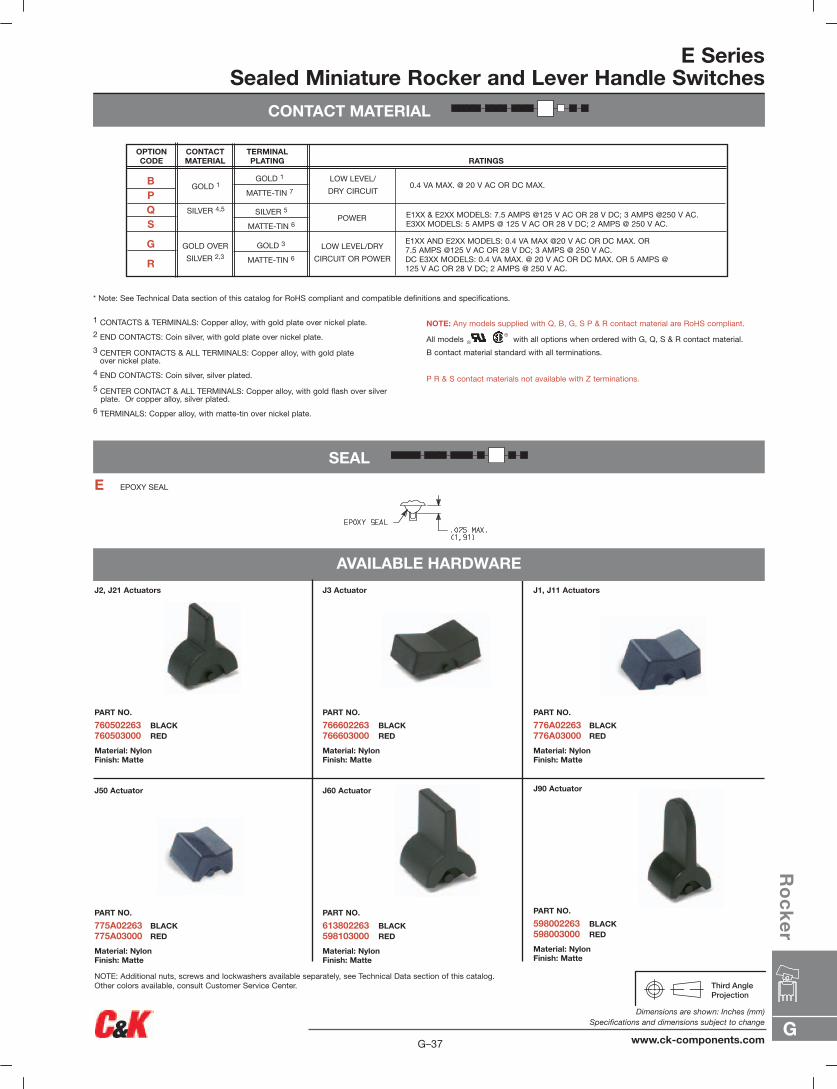
CONTACT MATERIAL
SEAL
AVAILABLE HARDWARE
J2, J21 Actuators
PART NO.
760502263 BLACK760503000 RED
Material: NylonFinish: Matte
J50 Actuator
PART NO.
775A02263 BLACK775A03000 RED
Material: NylonFinish: Matte
J60 Actuator
PART NO.
613802263 BLACK598103000 RED
Material: NylonFinish: Matte
J90 Actuator
PART NO.
598002263 BLACK598003000 RED
Material: NylonFinish: Matte
J3 Actuator
PART NO.
766602263 BLACK766603000 RED
Material: NylonFinish: Matte
J1, J11 Actuators
PART NO.
776A02263 BLACK776A03000 RED
Material: NylonFinish: Matte
NOTE: Additional nuts, screws and lockwashers available separately, see Technical Data section of this catalog.Other colors available, consult Customer Service Center.
* Note: See Technical Data section of this catalog for RoHS compliant and compatible definitions and specifications.
1 CONTACTS & TERMINALS: Copper alloy, with gold plate over nickel plate.
2 END CONTACTS: Coin silver, with gold plate over nickel plate.
3 CENTER CONTACTS & ALL TERMINALS: Copper alloy, with gold plateover nickel plate.
4 END CONTACTS: Coin silver, silver plated.
5 CENTER CONTACT & ALL TERMINALS: Copper alloy, with gold flash over silverplate. Or copper alloy, silver plated.
6 TERMINALS: Copper alloy, with matte-tin over nickel plate.
NOTE: Any models supplied with Q, B, G, S P & R contact material are RoHS compliant.
All models with all options when ordered with G, Q, S & R contact material.
B contact material standard with all terminations.
P R & S contact materials not available with Z terminations.
E EPOXY SEAL
OPTION CODE
CONTACT MATERIAL
TERMINALPLATING RATINGS
SILVER 5
MATTE-TIN 6
GOLD 1
SILVER 4,5
GOLD OVER
SILVER 2,3
GOLD 3
MATTE-TIN 6
GOLD 1
MATTE-TIN 7
LOW LEVEL/
DRY CIRCUIT
POWER
LOW LEVEL/DRY
CIRCUIT OR POWER
0.4 VA MAX. @ 20 V AC OR DC MAX.
E1XX & E2XX MODELS: 7.5 AMPS @125 V AC OR 28 V DC; 3 AMPS @250 V AC.E3XX MODELS: 5 AMPS @ 125 V AC OR 28 V DC; 2 AMPS @ 250 V AC.
E1XX AND E2XX MODELS: 0.4 VA MAX @20 V AC OR DC MAX. OR7.5 AMPS @125 V AC OR 28 V DC; 3 AMPS @ 250 V AC.DC E3XX MODELS: 0.4 VA MAX. @ 20 V AC OR DC MAX. OR 5 AMPS @125 V AC OR 28 V DC; 2 AMPS @ 250 V AC.
BPQS
G
R
E SeriesSealed Miniature Rocker and Lever Handle Switches
AVAILABLE HARDWARE
.495 – .505(12,57 – 12,83)
.797 – .803(20,24 – 20,40)
.005 R. MAX.(0,13) TYP.
.495 – .505(12,57 – 12,83)
.595 – .605(15,11 – 15,37)
.005 R.(0,13)MAX. TYP.
.495 – .505(12,57 – 12,83)
.620 – .625(15,75 – 15,88)
.005 R.(0,13)MAX. TYP.
PANEL MOUNTING
For part numbers4529xxxxx, 4527xxxxx,4528xxxxx, 4526xxxxx
For part numbers4325xxxxx, 4326xxxxx
For part numbers4327xxxxx, 4328xxxxx
TYPICAL APPLICATION
Fits Z3 Terminationfemale connector
PART NO.
530100000
Available in loose pieces.
Frame for J11, J21 Actuators
PART NO.
764500746 BLACK ENAMEL764601106 RETAINING SPRING
Material: Spring Steel
J50, J60 & J90 Actuators
MATTE
PART NO.
486702000
Material: NylonFinish: Matte or Gloss
GLOSS
PART NO.
486802000 BLACK
NOTE: Additional nuts, screws and lockwashers available separately, see Technical Data section of this catalog. Other colors available, consult Customer Service Center.
Frames snap into panel opening and are independent from switch mounting. Accurate positioning of the PCmounted switch relative to the panel opening is necessary to provide proper clearance between actuator and frame.Available in two basic styles and four panel thicknesses .047-.125 in. Material: Nylon. Finish: Matte.
J1 & J2 Actuators
J50, J60 & J90 Actuators
.125” (3,18) PANEL THK.
PART NO.
452602263 BLACK452603000 RED
.047” (1,19) PANEL THK.
PART NO.
452902263452903000
.062” (1,57) PANEL THK.
PART NO.
452702263452703000
.090” (2,29) PANEL THK.
PART NO.
452802263452803000
.125” (3,18) PANEL THK.
PART NO.
432802263 BLACK432803000 RED
.047” (1,19) PANEL THK.
PART NO.
432502263432503000
.062” (1,57) PANEL THK.
PART NO.
432602263432603000
.090” (2,29) PANEL THK.
PART NO.
432702263432703000
G–38
Dimensions are shown: Inches (mm)Specifications and dimensions subject to change
www.ck-components.comG
Ro
ck
er
AVAILABLE HARDWARE
E SeriesSealed Miniature Rocker and Lever Handle Switches
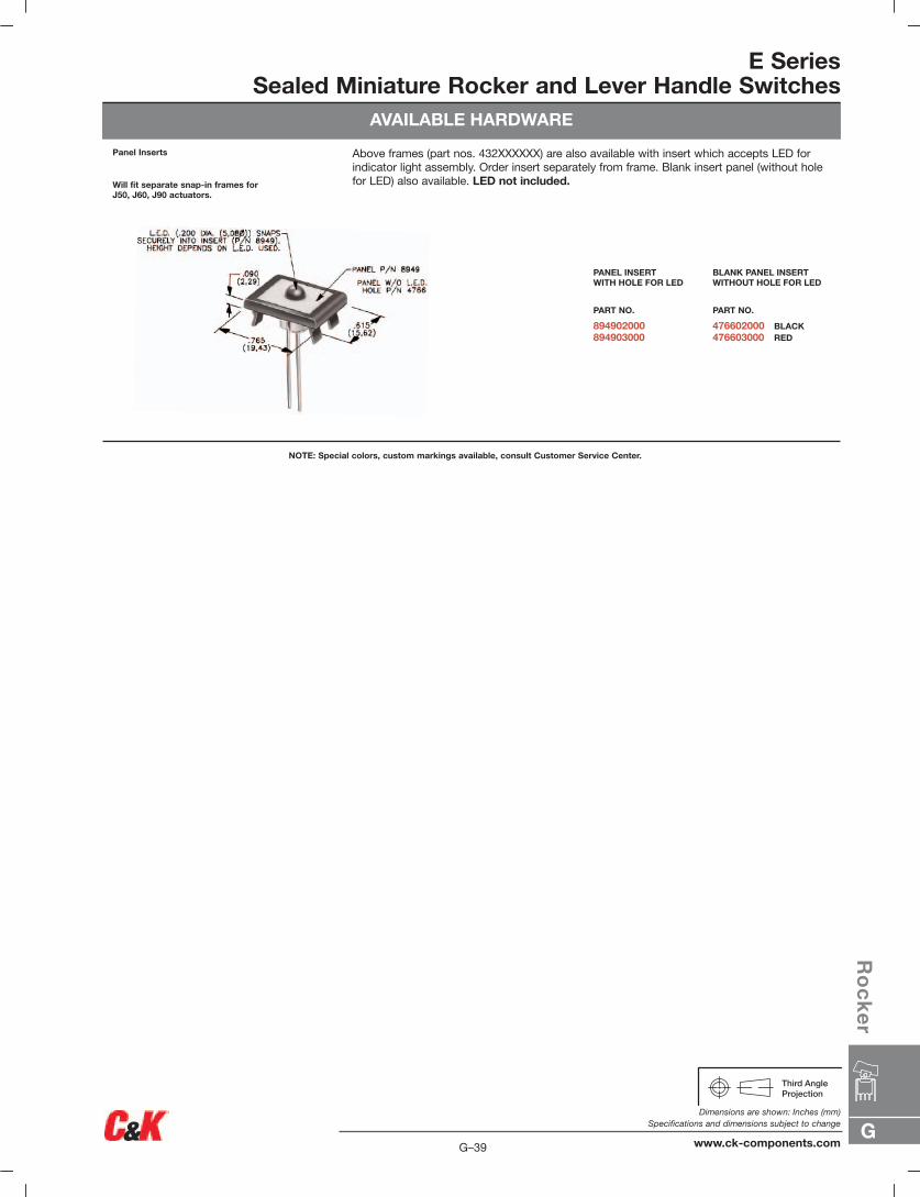
Above frames (part nos. 432XXXXXX) are also available with insert which accepts LED for indicator light assembly. Order insert separately from frame. Blank insert panel (without holefor LED) also available. LED not included.
Panel Inserts
Will fit separate snap-in frames forJ50, J60, J90 actuators.
NOTE: Special colors, custom markings available, consult Customer Service Center.
BLANK PANEL INSERTWITHOUT HOLE FOR LED
PART NO.
476602000 BLACK476603000 RED
PANEL INSERTWITH HOLE FOR LED
PART NO.
894902000894903000
G
Ro
ck
er
G–39
Dimensions are shown: Inches (mm)Specifications and dimensions subject to change
www.ck-components.com
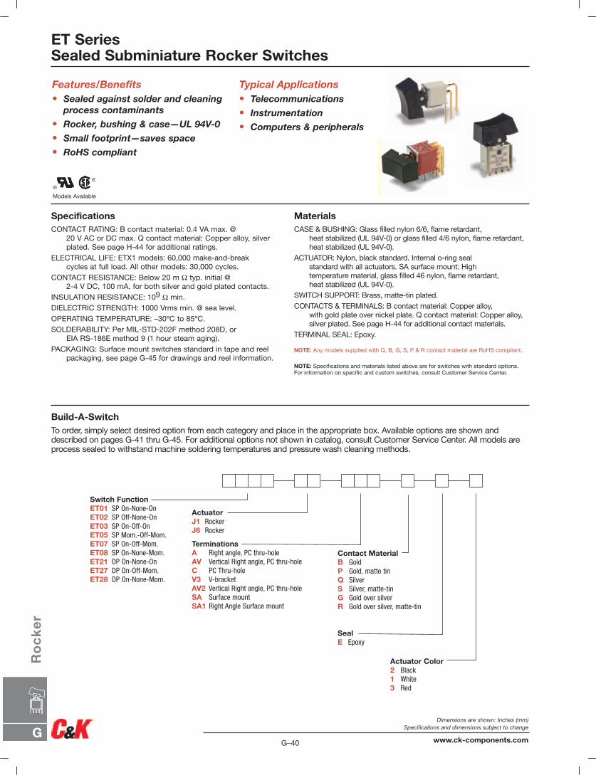
ET SeriesSealed Subminiature Rocker Switches
Models Available
Features/Benefits• Sealed against solder and cleaning
process contaminants
• Rocker, bushing & case—UL 94V-0
• Small footprint—saves space
• RoHS compliant
Typical Applications• Telecommunications
• Instrumentation
• Computers & peripherals
SpecificationsCONTACT RATING: B contact material: 0.4 VA max. @
20 V AC or DC max. Q contact material: Copper alloy, silverplated. See page H-44 for additional ratings.
ELECTRICAL LIFE: ETX1 models: 60,000 make-and-breakcycles at full load. All other models: 30,000 cycles.
CONTACT RESISTANCE: Below 20 m Ω typ. initial @2-4 V DC, 100 mA, for both silver and gold plated contacts.
INSULATION RESISTANCE: 109 Ω min.DIELECTRIC STRENGTH: 1000 Vrms min. @ sea level.OPERATING TEMPERATURE: –30ºC to 85ºC.SOLDERABILITY: Per MIL-STD-202F method 208D, or
EIA RS-186E method 9 (1 hour steam aging).PACKAGING: Surface mount switches standard in tape and reel
packaging, see page G-45 for drawings and reel information.
MaterialsCASE & BUSHING: Glass filled nylon 6/6, flame retardant,
heat stabilized (UL 94V-0) or glass filled 4/6 nylon, flame retardant,heat stabilized (UL 94V-0).
ACTUATOR: Nylon, black standard. Internal o-ring sealstandard with all actuators. SA surface mount: Hightemperature material, glass filled 46 nylon, flame retardant,heat stabilized (UL 94V-0).
SWITCH SUPPORT: Brass, matte-tin plated.CONTACTS & TERMINALS: B contact material: Copper alloy,
with gold plate over nickel plate. Q contact material: Copper alloy,silver plated. See page H-44 for additional contact materials.
TERMINAL SEAL: Epoxy.
NOTE: Any models supplied with Q, B, G, S, P & R contact material are RoHS compliant.
NOTE: Specifications and materials listed above are for switches with standard options. For information on specific and custom switches, consult Customer Service Center.
Build-A-SwitchTo order, simply select desired option from each category and place in the appropriate box. Available options are shown anddescribed on pages G-41 thru G-45. For additional options not shown in catalog, consult Customer Service Center. All models areprocess sealed to withstand machine soldering temperatures and pressure wash cleaning methods.
Switch FunctionET01 SP On-None-OnET02 SP Off-None-OnET03 SP On-Off-OnET05 SP Mom.-Off-Mom.ET07 SP On-Off-Mom.ET08 SP On-None-Mom.ET21 DP On-None-OnET27 DP On-Off-Mom.ET28 DP On-None-Mom.
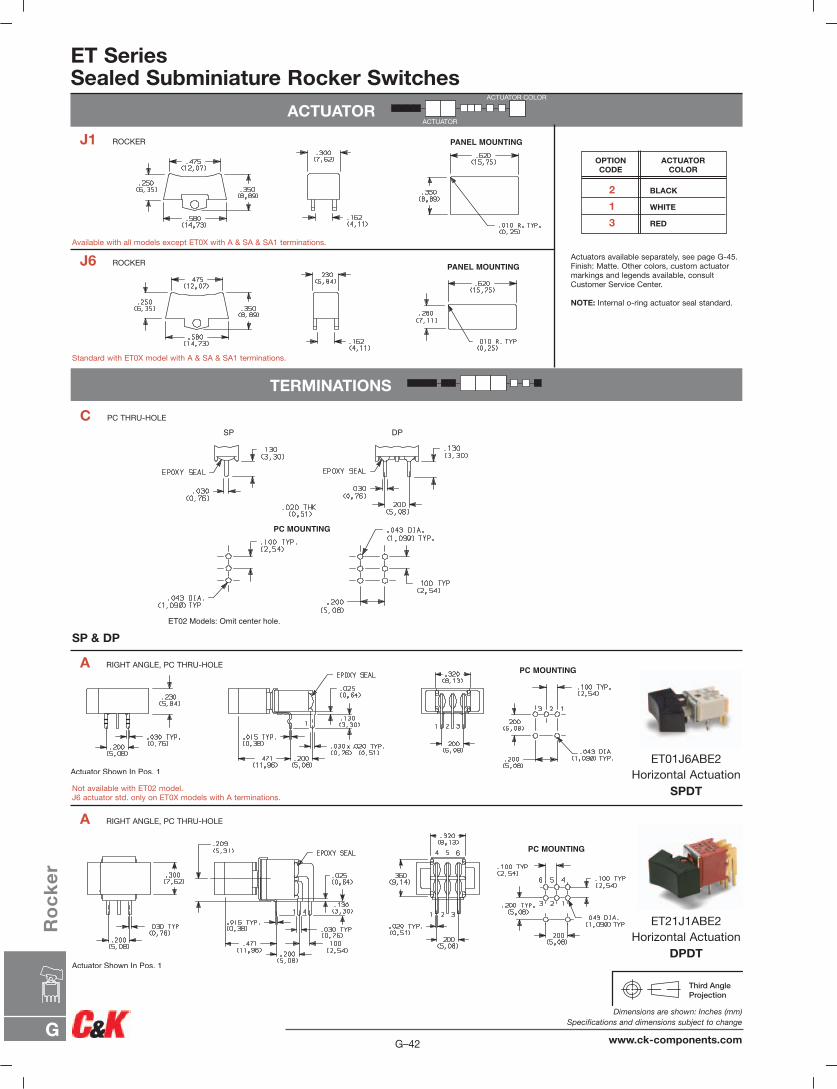
ActuatorJ1 RockerJ6 Rocker
TerminationsA Right angle, PC thru-holeAV Vertical Right angle, PC thru-holeC PC Thru-holeV3 V-bracketAV2 Vertical Right angle, PC thru-holeSA Surface mountSA1 Right Angle Surface mount
Contact MaterialB GoldP Gold, matte tinQ SilverS Silver, matte-tinG Gold over silverR Gold over silver, matte-tin
SealE Epoxy
Actuator Color2 Black1 White3 Red
G–40
Dimensions are shown: Inches (mm)Specifications and dimensions subject to change
www.ck-components.comG
Ro
ck
er
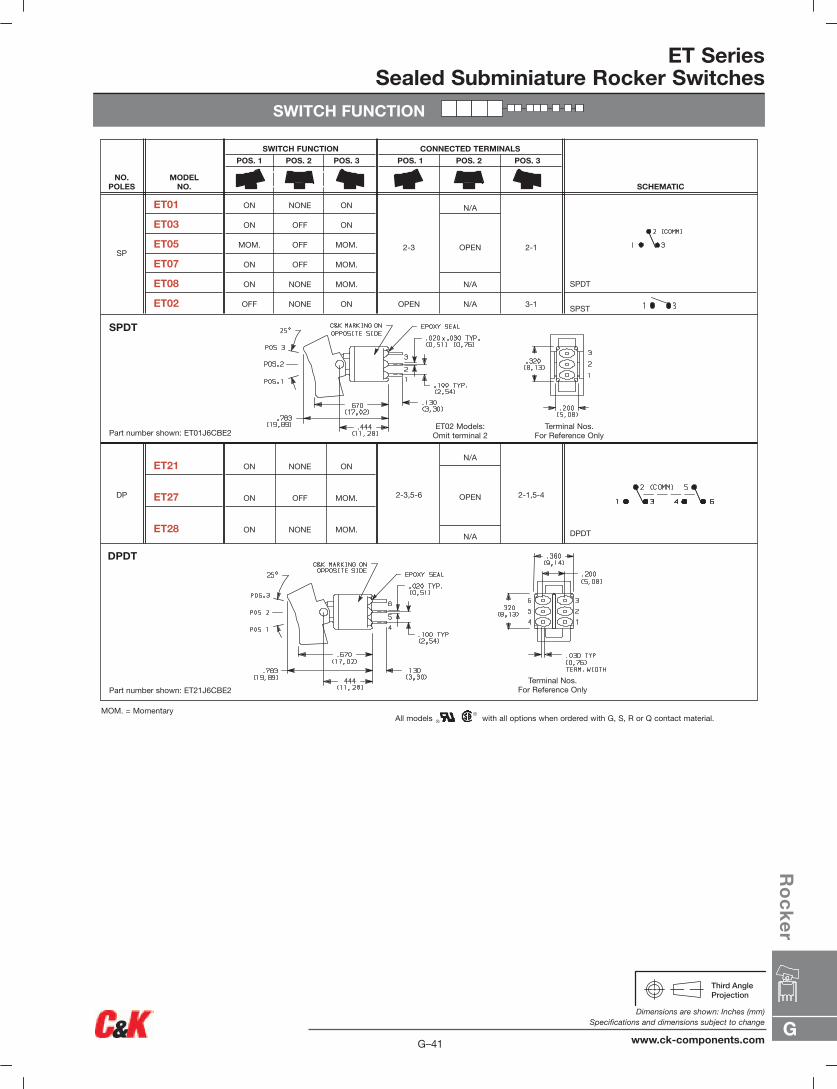
ET SeriesSealed Subminiature Rocker Switches
SWITCH FUNCTION
DPDT
2-1,5-4
N/A
OPEN
N/A
2-3,5-6
ON NONE ON
ON OFF MOM.
ON NONE MOM.
ET21
ET27
ET28
DP
SPDT
SPST
2-1
3-1
N/A
OPEN
N/A
N/A
2-3
OPEN
ON NONE ON
ON OFF ON
MOM. OFF MOM.
ON OFF MOM.
ON NONE MOM.
OFF NONE ON
ET01
ET03
ET05
ET07
ET08
ET02
SP
SCHEMATIC
CONNECTED TERMINALS
POS. 1 POS. 2 POS. 3
SWITCH FUNCTION
POS. 1 POS. 2 POS. 3
MODEL NO.
NO.POLES
DPDT
SPDT
Part number shown: ET01J6CBE2
Part number shown: ET21J6CBE2
All models with all options when ordered with G, S, R or Q contact material.MOM. = Momentary
Terminal Nos.For Reference Only
Terminal Nos.For Reference Only
ET02 Models:Omit terminal 2
G
Ro
ck
er
G–41
Dimensions are shown: Inches (mm)Specifications and dimensions subject to change
www.ck-components.com
ET SeriesSealed Subminiature Rocker Switches
ACTUATOR
TERMINATIONS
PANEL MOUNTING
PANEL MOUNTING
PC MOUNTING
PC MOUNTING
SP DP
Actuators available separately, see page G-45.Finish: Matte. Other colors, custom actuatormarkings and legends available, consultCustomer Service Center.
NOTE: Internal o-ring actuator seal standard.
2 BLACK
1 WHITE
3 RED
ACTUATORCOLOR
OPTION CODE
J1 ROCKER
C PC THRU-HOLE
A RIGHT ANGLE, PC THRU-HOLE
A RIGHT ANGLE, PC THRU-HOLE
J6 ROCKER
ET01J6ABE2Horizontal Actuation
SPDT
ET21J1ABE2Horizontal Actuation
DPDT
SP & DP
Available with all models except ET0X with A & SA & SA1 terminations.
Standard with ET0X model with A & SA & SA1 terminations.
Not available with ET02 model.J6 actuator std. only on ET0X models with A terminations.
ACTUATOR COLOR
ACTUATOR
G–42
Dimensions are shown: Inches (mm)Specifications and dimensions subject to change
www.ck-components.comG
Ro
ck
er

ET SeriesSealed Subminiature Rocker Switches
TERMINATIONS
PC MOUNTING
PC MOUNTING
PC MOUNTING
AV VERTICAL RIGHT ANGLE, PC THRU-HOLE
AV2 VERTICAL RIGHT ANGLE, PC THRU-HOLE
AV VERTICAL RIGHT ANGLE, PC THRU-HOLE
NOTE: Terminal bend radii and lead-in manufacturing option.
NOTE: Terminal bend radii and lead-in manufacturing option.
ET01J1AVBE2Vertical Actuation
SPDT
ET21J1AVBE2Vertical Actuation
DPDT
ET01J1AV2BE2Vertical Actuation
SPDT
.079 TYP.(2,0)
.200(5,08).051
(1,30)
.032 TYP.(0,80)
.272(6,90)
.059(1,50)
.071 TYP.(1,80)
.100(2,54)
.041(1,04)
.020 TYP(0,51)
.403(10,24)
.276(7,0)
.133(3,37)
.059(1,50)
.403(10,24)
.245(6,22)
.264(6,70)
.354(9,00)
.483(12,27)
.575(14,61)
.230(5,84)
2 13
EPOXY SEAL
SA1 SURFACE MOUNT
NOTE: Standard with tape & reel packaging, see page G-45.
NOTE: Available in B contactmaterials only.
Available in J6 actuator blackonly.
Not available in ET02.
ET01J6SA1BE2Horizontal Actuation
SPDT
PC MOUNTINGACTUATOR SHOWNPOS. 1
G
Ro
ck
er
G–43
Dimensions are shown: Inches (mm)Specifications and dimensions subject to change
www.ck-components.com
ET SeriesSealed Subminiature Rocker Switches
TERMINATIONS
CONTACT MATERIAL
PANEL MOUNTING
PC MOUNTING
1 2 3
.200(5,08)
PC MOUNTING
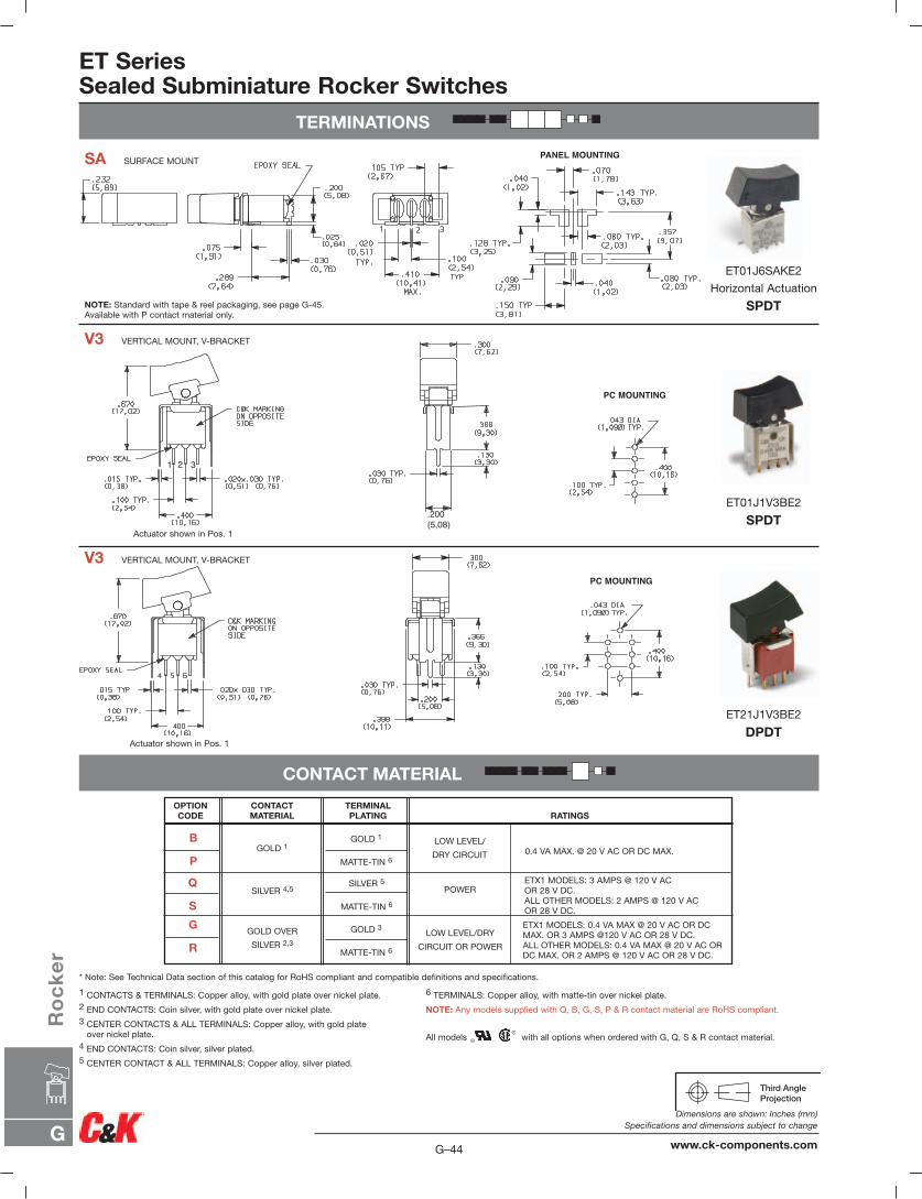
SA SURFACE MOUNT
V3 VERTICAL MOUNT, V-BRACKET
V3 VERTICAL MOUNT, V-BRACKET
Actuator shown in Pos. 1
Actuator shown in Pos. 1
NOTE: Standard with tape & reel packaging, see page G-45.Available with P contact material only.
ET21J1V3BE2
DPDT
ET01J1V3BE2
SPDT
ET01J6SAKE2
Horizontal Actuation
SPDT
* Note: See Technical Data section of this catalog for RoHS compliant and compatible definitions and specifications.
1 CONTACTS & TERMINALS: Copper alloy, with gold plate over nickel plate.2 END CONTACTS: Coin silver, with gold plate over nickel plate.3 CENTER CONTACTS & ALL TERMINALS: Copper alloy, with gold plate
over nickel plate.4 END CONTACTS: Coin silver, silver plated.5 CENTER CONTACT & ALL TERMINALS: Copper alloy, silver plated.
6 TERMINALS: Copper alloy, with matte-tin over nickel plate.
NOTE: Any models supplied with Q, B, G, S, P & R contact material are RoHS compliant.
All models with all options when ordered with G, Q, S & R contact material.
OPTION CODE
CONTACT MATERIAL
TERMINALPLATING RATINGS
SILVER 5
MATTE-TIN 6
GOLD 1
SILVER 4,5
GOLD OVER
SILVER 2,3
GOLD 3
MATTE-TIN 6
GOLD 1
MATTE-TIN 6
LOW LEVEL/
DRY CIRCUIT
POWER
LOW LEVEL/DRY
CIRCUIT OR POWER
0.4 VA MAX. @ 20 V AC OR DC MAX.
ETX1 MODELS: 3 AMPS @ 120 V AC OR 28 V DC.ALL OTHER MODELS: 2 AMPS @ 120 V AC OR 28 V DC.
ETX1 MODELS: 0.4 VA MAX @ 20 V AC OR DC MAX. OR 3 AMPS @120 V AC OR 28 V DC.ALL OTHER MODELS: 0.4 VA MAX @ 20 V AC OR DC MAX. OR 2 AMPS @ 120 V AC OR 28 V DC.
B
P
G
R
Q
S
G–44
Dimensions are shown: Inches (mm)Specifications and dimensions subject to change
www.ck-components.comG
Ro
ck
er
SEAL
ET SeriesSealed Subminiature Rocker Switches
AVAILABLE HARDWARE
TAPE & REEL SA TERMINATION
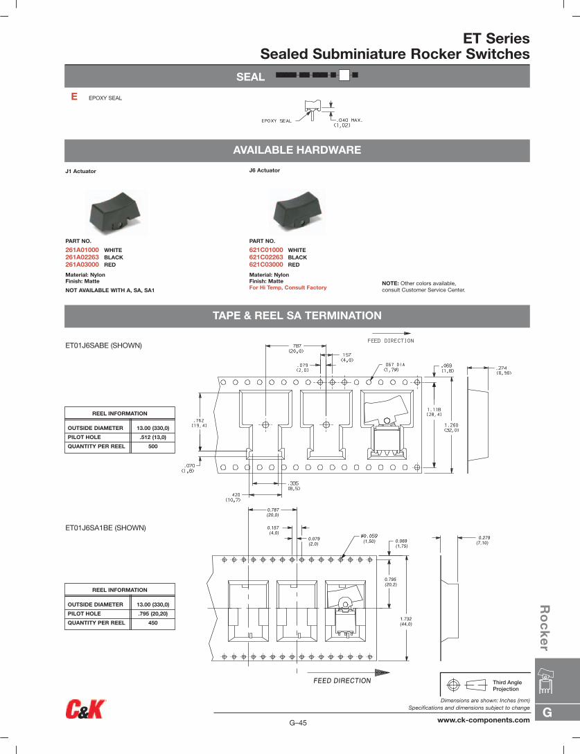
J1 Actuator
PART NO.
261A01000 WHITE261A02263 BLACK261A03000 RED
Material: NylonFinish: Matte
NOT AVAILABLE WITH A, SA, SA1
J6 Actuator
PART NO.
621C01000 WHITE621C02263 BLACK621C03000 RED
Material: NylonFinish: MatteFor Hi Temp, Consult Factory
E EPOXY SEAL
NOTE: Other colors available, consult Customer Service Center.
ET01J6SABE (SHOWN)
OUTSIDE DIAMETER 13.00 (330,0)
PILOT HOLE .512 (13,0)
QUANTITY PER REEL 500
REEL INFORMATION
FEED DIRECTION
0.079(2,0)
0.157(4,0)
0.069(1,75)
1.732(44,0)
0.795(20,2)
(1,50)
0.787(20,0)
0.279(7,10)
ET01J6SA1BE (SHOWN)
OUTSIDE DIAMETER 13.00 (330,0)
PILOT HOLE .795 (20,20)
QUANTITY PER REEL 450
REEL INFORMATION
G
Ro
ck
er
G–45
Dimensions are shown: Inches (mm)Specifications and dimensions subject to change
www.ck-components.com
G–46
Dimensions are shown: Inches (mm)Specifications and dimensions subject to change
www.ck-components.comG
Ro
ck
er
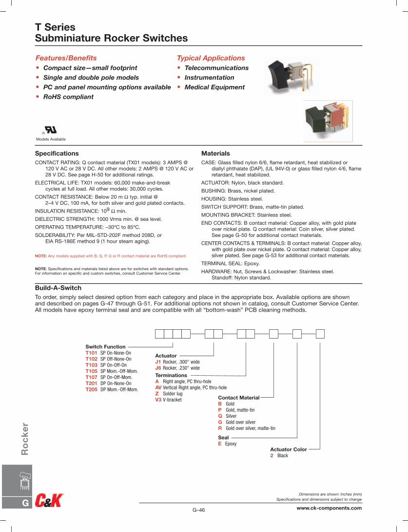
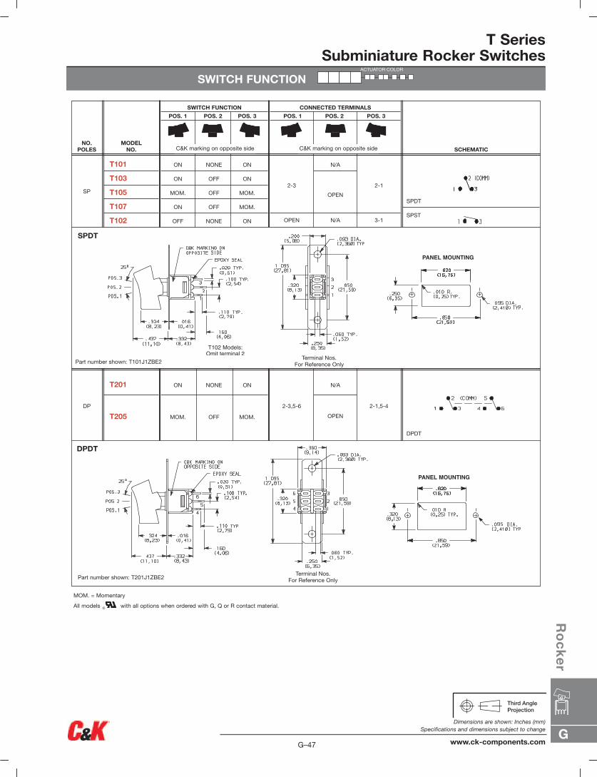
T SeriesSubminiature Rocker Switches
Models Available
Features/Benefits• Compact size—small footprint
• Single and double pole models
• PC and panel mounting options available
• RoHS compliant
Typical Applications• Telecommunications
• Instrumentation
• Medical Equipment
SpecificationsCONTACT RATING: Q contact material (TX01 models): 3 AMPS @
120 V AC or 28 V DC. All other models: 2 AMPS @ 120 V AC or28 V DC. See page H-50 for additional ratings.
ELECTRICAL LIFE: TX01 models: 60,000 make-and-breakcycles at full load. All other models: 30,000 cycles.
CONTACT RESISTANCE: Below 20 m Ω typ. initial @2–4 V DC, 100 mA, for both silver and gold plated contacts.
INSULATION RESISTANCE: 109 Ω min.
DIELECTRIC STRENGTH: 1000 Vrms min. @ sea level.
OPERATING TEMPERATURE: –30ºC to 85ºC.
SOLDERABILITY: Per MIL-STD-202F method 208D, orEIA RS-186E method 9 (1 hour steam aging).
NOTE: Any models supplied with B, G, P, Q or R contact material are RoHS compliant.
NOTE: Specifications and materials listed above are for switches with standard options.For information on specific and custom switches, consult Customer Service Center.
MaterialsCASE: Glass filled nylon 6/6, flame retardant, heat stabilized or
diallyl phthalate (DAP), (UL 94V-0) or glass filled nylon 4/6, flameretardant, heat stabilized.
ACTUATOR: Nylon, black standard.
BUSHING: Brass, nickel plated.
HOUSING: Stainless steel.
SWITCH SUPPORT: Brass, matte-tin plated.
MOUNTING BRACKET: Stainless steel.
END CONTACTS: B contact material: Copper alloy, with gold plateover nickel plate. Q contact material: Coin silver, silver plated.See page G-50 for additional contact materials.
CENTER CONTACTS & TERMINALS: B contact material: Copper alloy,with gold plate over nickel plate. Q contact material: Copper alloy,silver plated. See page G-53 for additional contact materials.
TERMINAL SEAL: Epoxy.
HARDWARE: Nut, Screws & Lockwasher: Stainless steel.Standoff: Nylon standard.
Build-A-SwitchTo order, simply select desired option from each category and place in the appropriate box. Available options are shown and described on pages G-47 through G-51. For additional options not shown in catalog, consult Customer Service Center. All models have epoxy terminal seal and are compatible with all “bottom-wash” PCB cleaning methods.
Switch FunctionT101 SP On-None-OnT102 SP Off-None-OnT103 SP On-Off-OnT105 SP Mom.-Off-Mom.T107 SP On-Off-Mom.T201 DP On-None-OnT205 DP Mom.-Off-Mom.
ActuatorJ1 Rocker, .300" wideJ6 Rocker, .230" wide
TerminationsA Right angle, PC thru-holeAV Vertical Right angle, PC thru-holeZ Solder lugV3 V-bracket Contact Material
B GoldP Gold, matte-tinQ SilverG Gold over silverR Gold over silver, matte-tin
SealE Epoxy
Actuator Color2 Black
G
Ro
ck
er
G–47
Dimensions are shown: Inches (mm)Specifications and dimensions subject to change
www.ck-components.com
T SeriesSubminiature Rocker Switches
SWITCH FUNCTION
DPDT
2-1,5-4
N/A
OPEN
2-3,5-6
ON NONE ON
MOM. OFF MOM.
T201
T205DP
SPDT
SPST
2-1
3-1
N/A
OPEN
N/A
2-3
OPEN
ON NONE ON
ON OFF ON
MOM. OFF MOM.
ON OFF MOM.
OFF NONE ON
T101
T103
T105
T107
T102
SP
SCHEMATIC
CONNECTED TERMINALS
POS. 1 POS. 2 POS. 3
SWITCH FUNCTION
POS. 1 POS. 2 POS. 3
MODEL NO.
NO.POLES
DPDT
SPDT
Part number shown: T101J1ZBE2
Part number shown: T201J1ZBE2
MOM. = Momentary
All models with all options when ordered with G, Q or R contact material.
Terminal Nos.For Reference Only
Terminal Nos.For Reference Only
C&K marking on opposite sideC&K marking on opposite side
PANEL MOUNTING
PANEL MOUNTING
ACTUATOR COLOR

T SeriesSubminiature Rocker Switches
ACTUATOR
PC MOUNTING
SP DP
Actuators available separately, see page G 51-G53. Finish: Matte. Other colors, custom actu-ator markings and legends available, consultCustomer Service Center.
2 BLACK
ACTUATORCOLOR
OPTION CODE
J1 ROCKER, .300 WIDE
A RIGHT ANGLE, PC THRU-HOLE
Z SOLDER LUG
J6 ROCKER, .230 WIDE
TERMINATIONS
SP and DP
T101J6ABE2Horizontal Actuation
SPDT
Standard with all models except T10X with A terminations.
Standard with T10X model with A terminations.
Not available with P or R contact material.
Not available with T102 model. J6 actuator standard onlyon T10X models with A terminations.
ACTUATOR
G–48
Dimensions are shown: Inches (mm)Specifications and dimensions subject to change
www.ck-components.comG
Ro
ck
er
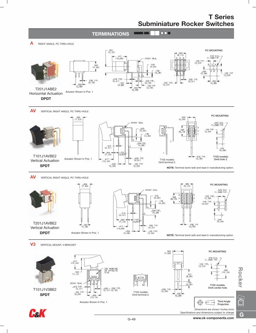
T SeriesSubminiature Rocker Switches
TERMINATIONS
V3 VERTICAL MOUNT, V-BRACKET
AV VERTICAL RIGHT ANGLE, PC THRU-HOLE
AV VERTICAL RIGHT ANGLE, PC THRU-HOLE
A RIGHT ANGLE, PC THRU-HOLE
NOTE: Terminal bend radii and lead-in manufacturing option.
NOTE: Terminal bend radii and lead-in manufacturing option.
T201J1ABE2Horizontal Actuation
DPDT
T101J1AVBE2Vertical Actuation
SPDT
T201J1AVBE2Vertical Actuation
DPDT
T101J1V3BE2SPDT
G
Ro
ck
er
G–49
Dimensions are shown: Inches (mm)Specifications and dimensions subject to change
www.ck-components.com
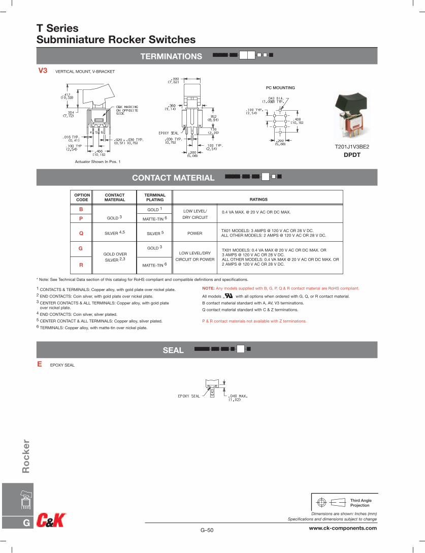
T SeriesSubminiature Rocker Switches
TERMINATIONS
V3 VERTICAL MOUNT, V-BRACKET
CONTACT MATERIAL
* Note: See Technical Data section of this catalog for RoHS compliant and compatible definitions and specifications.
1 CONTACTS & TERMINALS: Copper alloy, with gold plate over nickel plate.2 END CONTACTS: Coin silver, with gold plate over nickel plate.3 CENTER CONTACTS & ALL TERMINALS: Copper alloy, with gold plate
over nickel plate.4 END CONTACTS: Coin silver, silver plated.5 CENTER CONTACT & ALL TERMINALS: Copper alloy, silver plated.6 TERMINALS: Copper alloy, with matte-tin over nickel plate.
NOTE: Any models supplied with B, G, P, Q & R contact material are RoHS compliant.
All models with all options when ordered with G, Q, or R contact material.
B contact material standard with A, AV, V3 terminations.
Q contact material standard with C & Z terminations.
P & R contact materials not available with Z terminations.
SEAL
E EPOXY SEAL
T201J1V3BE2
DPDT
0.4 VA MAX. @ 20 V AC OR DC MAX.
TX01 MODELS: 3 AMPS @ 120 V AC OR 28 V DC.ALL OTHER MODELS: 2 AMPS @ 120 V AC OR 28 V DC.
TX01 MODELS: 0.4 VA MAX @ 20 V AC OR DC MAX. OR3 AMPS @ 120 V AC OR 28 V DC.ALL OTHER MODELS: 0.4 VA MAX @ 20 V AC OR DC MAX. OR2 AMPS @ 120 V AC OR 28 V DC.
RATINGS
B
P
Q
G
OPTION CODE
CONTACT MATERIAL
TERMINALPLATING
LOW LEVEL/
DRY CIRCUIT
POWER
LOW LEVEL/DRY
CIRCUIT OR POWER
GOLD 1
MATTE-TIN 6
SILVER 5
GOLD 3
GOLD 3
SILVER 4,5
GOLD OVER
SILVER 2,3
R MATTE-TIN 6
G–50
Dimensions are shown: Inches (mm)Specifications and dimensions subject to change
www.ck-components.comG
Ro
ck
er
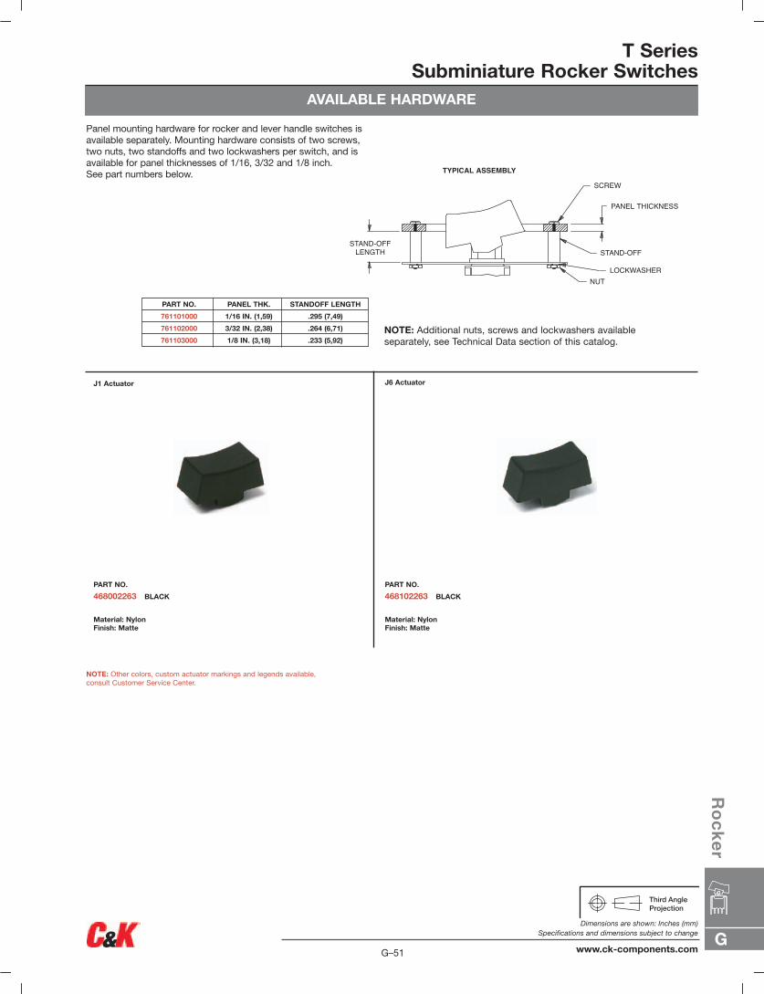
T SeriesSubminiature Rocker Switches
AVAILABLE HARDWARE
J1 Actuator
PART NO.
468002263 BLACK
Material: NylonFinish: Matte
J6 Actuator
PART NO.
468102263 BLACK
Material: NylonFinish: Matte
NOTE: Other colors, custom actuator markings and legends available, consult Customer Service Center.
NOTE: Additional nuts, screws and lockwashers availableseparately, see Technical Data section of this catalog.
TYPICAL ASSEMBLY
SCREW
PANEL THICKNESS
STAND-OFF
LOCKWASHERNUT
STAND-OFFLENGTH
Panel mounting hardware for rocker and lever handle switches isavailable separately. Mounting hardware consists of two screws,two nuts, two standoffs and two lockwashers per switch, and isavailable for panel thicknesses of 1/16, 3/32 and 1/8 inch. See part numbers below.
PART NO. PANEL THK. STANDOFF LENGTH
761101000 1/16 IN. (1,59) .295 (7,49)
761102000 3/32 IN. (2,38) .264 (6,71)
761103000 1/8 IN. (3,18) .233 (5,92)
G
Ro
ck
er
G–51
Dimensions are shown: Inches (mm)Specifications and dimensions subject to change
www.ck-components.com
Models Available
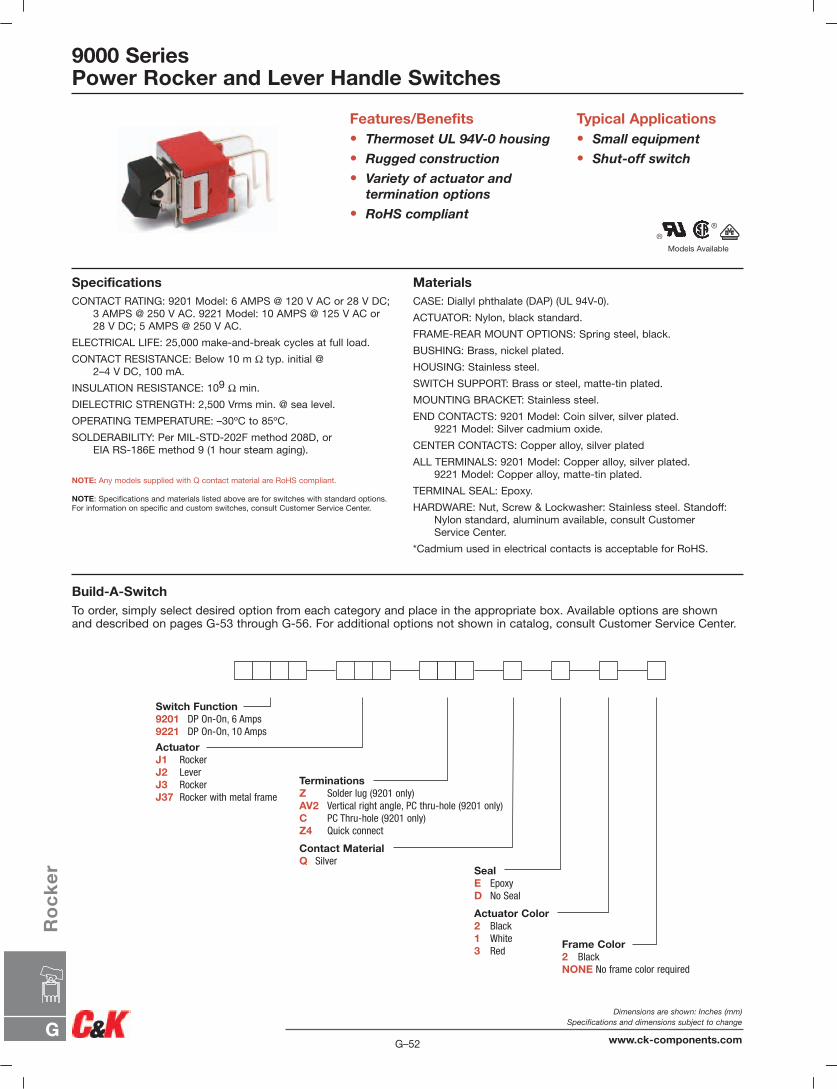
9000 SeriesPower Rocker and Lever Handle Switches
Features/Benefits• Thermoset UL 94V-0 housing
• Rugged construction
• Variety of actuator andtermination options
• RoHS compliant
Typical Applications• Small equipment
• Shut-off switch
SpecificationsCONTACT RATING: 9201 Model: 6 AMPS @ 120 V AC or 28 V DC;
3 AMPS @ 250 V AC. 9221 Model: 10 AMPS @ 125 V AC or28 V DC; 5 AMPS @ 250 V AC.
ELECTRICAL LIFE: 25,000 make-and-break cycles at full load.
CONTACT RESISTANCE: Below 10 m Ω typ. initial @2–4 V DC, 100 mA.
INSULATION RESISTANCE: 109 Ω min.
DIELECTRIC STRENGTH: 2,500 Vrms min. @ sea level.
OPERATING TEMPERATURE: –30ºC to 85ºC.
SOLDERABILITY: Per MIL-STD-202F method 208D, orEIA RS-186E method 9 (1 hour steam aging).
NOTE: Any models supplied with Q contact material are RoHS compliant.
NOTE: Specifications and materials listed above are for switches with standard options.For information on specific and custom switches, consult Customer Service Center.
MaterialsCASE: Diallyl phthalate (DAP) (UL 94V-0).
ACTUATOR: Nylon, black standard.
FRAME-REAR MOUNT OPTIONS: Spring steel, black.
BUSHING: Brass, nickel plated.
HOUSING: Stainless steel.
SWITCH SUPPORT: Brass or steel, matte-tin plated.
MOUNTING BRACKET: Stainless steel.
END CONTACTS: 9201 Model: Coin silver, silver plated.9221 Model: Silver cadmium oxide.
CENTER CONTACTS: Copper alloy, silver plated
ALL TERMINALS: 9201 Model: Copper alloy, silver plated.9221 Model: Copper alloy, matte-tin plated.
TERMINAL SEAL: Epoxy.
HARDWARE: Nut, Screw & Lockwasher: Stainless steel. Standoff:Nylon standard, aluminum available, consult Customer Service Center.
*Cadmium used in electrical contacts is acceptable for RoHS.
Build-A-SwitchTo order, simply select desired option from each category and place in the appropriate box. Available options are shown and described on pages G-53 through G-56. For additional options not shown in catalog, consult Customer Service Center.
Switch Function9201 DP On-On, 6 Amps9221 DP On-On, 10 Amps
ActuatorJ1 RockerJ2 LeverJ3 RockerJ37 Rocker with metal frame
Actuator Color2 Black1 White3 Red
Frame Color2 BlackNONE No frame color required
Contact MaterialQ Silver
TerminationsZ Solder lug (9201 only)AV2 Vertical right angle, PC thru-hole (9201 only)C PC Thru-hole (9201 only)Z4 Quick connect
SealE EpoxyD No Seal
G–52
Dimensions are shown: Inches (mm)Specifications and dimensions subject to change
www.ck-components.comG
Ro
ck
er
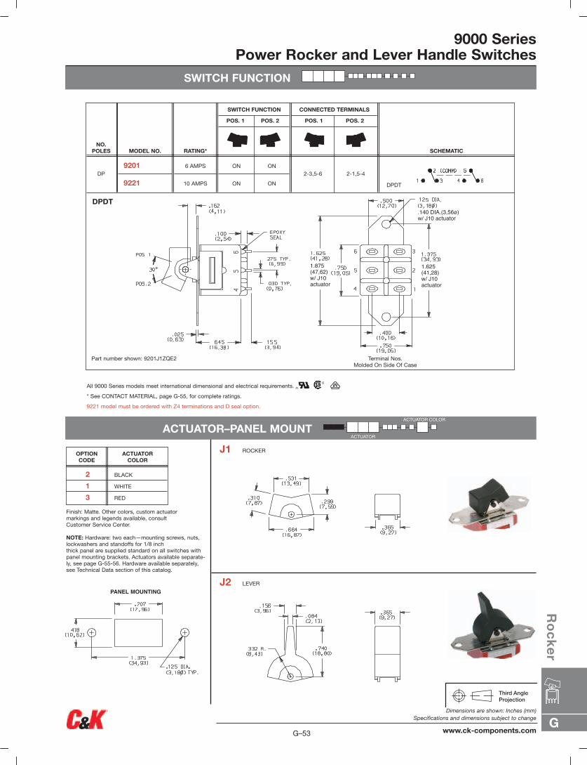
9000 SeriesPower Rocker and Lever Handle Switches
SWITCH FUNCTION
PANEL MOUNTING
1.875(47,62)w/ J10actuator
1.625(41,28)w/ J10actuator
.140 DIA.(3,56ø) w/ J10 actuator
DPDT
2-1,5-42-3,5-6ON
ON
ON
ON
6 AMPS
10 AMPS
9201
9221 DP
SCHEMATIC
CONNECTED TERMINALS
POS. 1 POS. 2
SWITCH FUNCTION
POS. 1 POS. 2
RATING*MODEL NO.NO.
POLES
DPDT
Part number shown: 9201J1ZQE2 Terminal Nos.Molded On Side Of Case
All 9000 Series models meet international dimensional and electrical requirements.
* See CONTACT MATERIAL, page G-55, for complete ratings.
9221 model must be ordered with Z4 terminations and D seal option.
ACTUATOR–PANEL MOUNT
Finish: Matte. Other colors, custom actuator markings and legends available, consult Customer Service Center.
NOTE: Hardware: two each—mounting screws, nuts,lockwashers and standoffs for 1/8 inch thick panel are supplied standard on all switches withpanel mounting brackets. Actuators available separate-ly, see page G-55-56. Hardware available separately,see Technical Data section of this catalog.
2 BLACK
1 WHITE
3 RED
ACTUATORCOLOR
OPTION CODE
J1 ROCKER
J2 LEVER
ACTUATOR COLOR
ACTUATOR
G
Ro
ck
er
G–53
Dimensions are shown: Inches (mm)Specifications and dimensions subject to change
www.ck-components.com
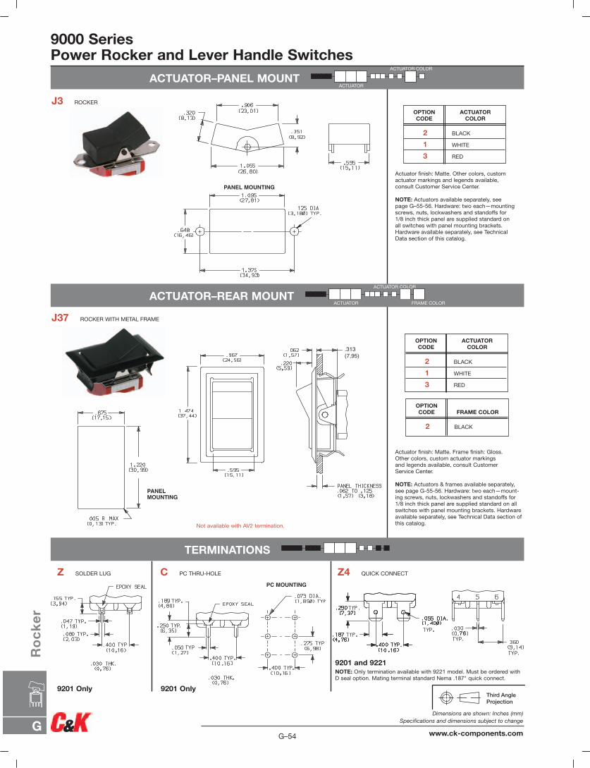
9000 SeriesPower Rocker and Lever Handle Switches
.313(7,95)
PANEL MOUNTING
PANELMOUNTING
PC MOUNTING
Actuator finish: Matte. Other colors, custom actuator markings and legends available, consult Customer Service Center.
NOTE: Actuators available separately, seepage G–55-56. Hardware: two each—mountingscrews, nuts, lockwashers and standoffs for1/8 inch thick panel are supplied standard onall switches with panel mounting brackets.Hardware available separately, see TechnicalData section of this catalog.
2 BLACK
1 WHITE
3 RED
ACTUATORCOLOR
OPTION CODE
Actuator finish: Matte. Frame finish: Gloss. Other colors, custom actuator markings and legends available, consult Customer Service Center.
NOTE: Actuators & frames available separately,see page G-55-56. Hardware: two each—mount-ing screws, nuts, lockwashers and standoffs for1/8 inch thick panel are supplied standard on allswitches with panel mounting brackets. Hardwareavailable separately, see Technical Data section ofthis catalog.Not available with AV2 termination.
2 BLACK
1 WHITE
3 RED
ACTUATORCOLOR
OPTION CODE
2 BLACK
FRAME COLOROPTION CODE
J3 ROCKER
J37 ROCKER WITH METAL FRAME
Z SOLDER LUG C PC THRU-HOLE
9201 and 9221NOTE: Only termination available with 9221 model. Must be ordered withD seal option. Mating terminal standard Nema .187" quick connect.
9201 Only9201 Only
Z4 QUICK CONNECT
ACTUATOR–REAR MOUNT
TERMINATIONS
ACTUATOR–PANEL MOUNTACTUATOR
ACTUATOR COLOR
ACTUATOR COLOR
FRAME COLORACTUATOR
G–54
Dimensions are shown: Inches (mm)Specifications and dimensions subject to change
www.ck-components.comG
Ro
ck
er
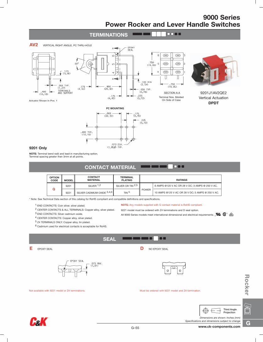
9000 SeriesPower Rocker and Lever Handle Switches
TERMINATIONS
CONTACT MATERIAL
SEAL
AV2 VERTICAL RIGHT ANGLE, PC THRU-HOLE
9201J1AV2QE2Vertical Actuation
DPDT
NOTE: Terminal bend radii and lead-in manufacturing option.Terminal spacing greater than 3mm at all points.
Terminal Nos. MoldedOn Side of Case
Not available with 9221 model or Z4 terminations. Must be ordered with 9221 model and Z4 termination.
9201 Only
1 END CONTACTS: Coin silver, silver plated.2 CENTER CONTACTS & ALL TERMINALS: Copper alloy, silver plated.3 END CONTACTS: Silver cadmium oxide.4 CENTER CONTACTS: Copper alloy, silver plated.5 Z4 TERMINALS ONLY: Copper alloy, tin plated.6 Cadmium used for electrical contacts is acceptable for RoHS.
NOTE: Any models supplied with Q contact material is RoHS compliant.
9221 model must be ordered with Z4 terminations and D seal option.
All 9000 Series models meet international dimensional and electrical requirements.
* Note: See Technical Data section of this catalog for RoHS compliant and compatible definitions and specifications.
E EPOXY SEAL D NO EPOXY SEAL
OPTION CODE
Q9201
9221
MODELCONTACT MATERIAL
SILVER 1,2
SILVER CADMIUM OXIDE 3,4,0
SILVER OR TIN 2,5
TIN 5
TERMINAL PLATING RATINGS
POWER
6 AMPS @120 V AC OR 28 V DC; 3 AMPS @ 250 V AC.
10 AMPS @125 V AC OR 28 V DC; 5 AMPS @ 250 V AC.
G
Ro
ck
er
G–55
Dimensions are shown: Inches (mm)Specifications and dimensions subject to change
www.ck-components.com
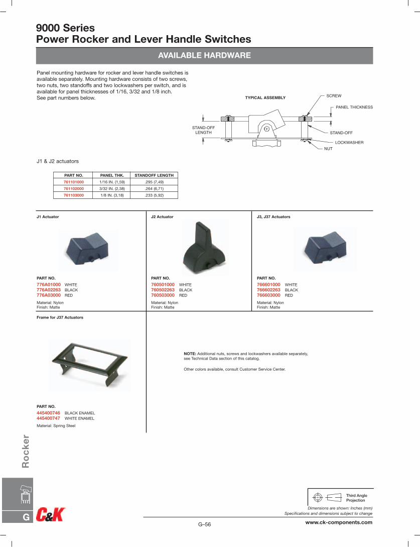
9000 SeriesPower Rocker and Lever Handle Switches
AVAILABLE HARDWARE
Panel mounting hardware for rocker and lever handle switches isavailable separately. Mounting hardware consists of two screws,two nuts, two standoffs and two lockwashers per switch, and isavailable for panel thicknesses of 1/16, 3/32 and 1/8 inch. See part numbers below.
J1 & J2 actuators
PART NO. PANEL THK. STANDOFF LENGTH
761101000 1/16 IN. (1,59) .295 (7,49)
761102000 3/32 IN. (2,38) .264 (6,71)
761103000 1/8 IN. (3,18) .233 (5,92)
J1 Actuator
PART NO.
776A01000 WHITE776A02263 BLACK776A03000 RED
Material: NylonFinish: Matte
Frame for J37 Actuators
PART NO.
445400746 BLACK ENAMEL445400747 WHITE ENAMEL
Material: Spring Steel
J2 Actuator
PART NO.
760501000 WHITE760502263 BLACK760503000 RED
Material: NylonFinish: Matte
J3, J37 Actuators
PART NO.
766601000 WHITE766602263 BLACK766603000 RED
Material: NylonFinish: Matte
TYPICAL ASSEMBLY SCREW
PANEL THICKNESS
STAND-OFF
LOCKWASHERNUT
STAND-OFFLENGTH
NOTE: Additional nuts, screws and lockwashers available separately, see Technical Data section of this catalog.
Other colors available, consult Customer Service Center.
G–56
Dimensions are shown: Inches (mm)Specifications and dimensions subject to change
www.ck-components.comG
Ro
ck
er
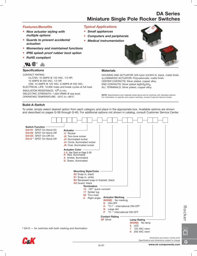
DA SeriesMiniature Single Pole Rocker Switches
Build-A-SwitchTo order, simply select desired option from each category and place in the appropriate box. Available options are shown and described on pages G-58 through G-60. For additional options not shown in catalog, consult Customer Service Center.
SpecificationsCONTACT RATING:
UL/CSA: 16 AMPS @ 125 VAC, 1/3 HP;10 AMPS @ 250 VAC, 1/2 HP.VDE: 10 AMPS @ 125 VAC, 6 AMPS @ 250 VAC.
ELECTRICAL LIFE: 10,000 make and break cycles at full load.
INSULATION RESISTANCE: 108 Ω min.DIELECTRIC STRENGTH: 1,500 VRMS @ sea level.OPERATING TEMPERATURE: -20ºC to +85ºC
Features/Benefits• Nice actuator styling with
multiple options
• Guards to prevent accidental actuation
• Momentary and maintained functions
• IP65 splash proof rubber boot option
• RoHS compliant
MaterialsHOUSING AND ACTUATOR: 6/6 nylon (UL94V-2), black, matte finish.ILLUMINATED ACTUATOR: Polycarbonate, matte finish.CENTER CONTACTS: Silver plated, copper alloy.END CONTACTS: Silver plated AgSn02ln03.ALL TERMINALS: Silver plated, copper alloy.
NOTE: Specifications and materials listed above are for switches with standard options. For information on specific and custom switches, consult Customer Service Center.
Typical Applications• Small appliances
• Computers and peripherals
• Medical instrumentation
Lamp Rating(NONE) No lamp6 LED7 125 VAC neon8 250 VAC neon
ActuatorJ1 RockerJ2 Two-tone rockerJ3 Illuminated rockerJ4 Circle, illuminated rockerJ5 Oval, illuminated rocker
Switch FunctionDA101 SPDT On-None-OnDA102 SPST On-None-OffDA103 SPDT On-Off-OnDA12 * SPST On-None-Off
Actuator Color1-5 See Chart on Page G-59R Red, illuminatedA Amber, illuminatedG Green, illuminated
Contact RatingQF Silver
Mounting Style/ColorS2 Snap-in, blackS1 Snap-in, whiteB2 Recessed snap-in bracket, blackG2 Guard, black
Actuator Marking(NONE) No markingD ON-OFFH ”O l” - international ON-OFFN Large dotP ”O -” international ON-OFF
Termination15 .187” quick connect17 Solder lug02 Thru-holeA Right angle
* DA12 — for switches with both marking and illumination
G
Ro
ck
er
G–57
Dimensions are shown: Inches (mm)Specifications and dimensions subject to change
www.ck-components.com
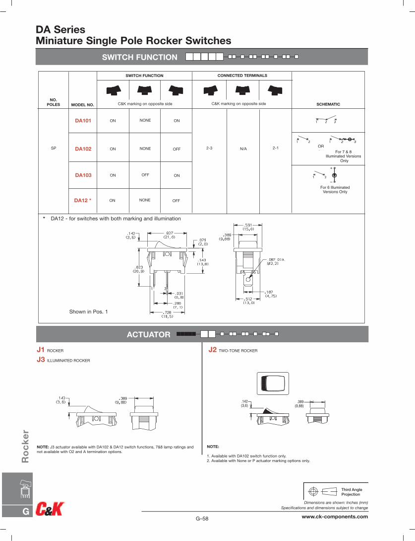
SWITCH FUNCTION
DA SeriesMiniature Single Pole Rocker Switches
SWITCH FUNCTION CONNECTED TERMINALS
C&K marking on opposite side C&K marking on opposite sideNO.
POLES MODEL NO. SCHEMATIC
SP
ON ON
ON OFF
DA101
DA102 2-3 2-1 ORFor 7 & 8
Illuminated VersionsOnly
NONE
NONE N/A
For 6 IlluminatedVersions Only
+
–
ACTUATOR
J1 ROCKER J2 TWO-TONE ROCKER
J3 ILLUMINATED ROCKER
.389(9,88)
.142(3,6)
ON ONDA103 OFF
ON OFFDA12 * NONE
* DA12 - for switches with both marking and illumination
Shown in Pos. 1
NOTE: J3 actuator available with DA102 & DA12 switch functions, 7&8 lamp ratings andnot available with O2 and A termination options.
NOTE:
1. Available with DA102 switch function only.2. Available with None or P actuator marking options only.
OR
For IlluminatedVersion
G–58
Dimensions are shown: Inches (mm)Specifications and dimensions subject to change
www.ck-components.comG
Ro
ck
er
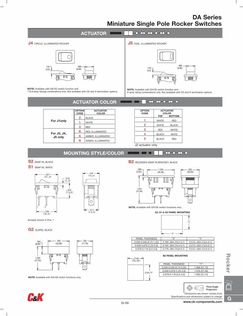
ACTUATOR
DA SeriesMiniature Single Pole Rocker Switches
ACTUATOR COLOR
OPTION ACTUATORCODE COLOR
2 BLACK
1 WHITE
3 RED
R RED, ILLUMINATED
A AMBER, ILLUMINATED
G GREEN, ILLUMINATED
J4 CIRCLE, ILLUMINATED ROCKER
NOTE: Available with DA102 switch function and7 & 8 lamp ratings combinations only. Not available with O2 and A termination options.
J5 OVAL, ILLUMINATED ROCKER
NOTE: Available with DA102 switch function and6 lamp rating combinations only. Not available with O2 and A termination options.
.389(9,88)
.142(3,6)
.389(9,88).142
(3,6)
MOUNTING STYLE/COLOR
S2, S1 & G2 PANEL MOUNTING
PANEL THICKNESS “X” “Y”
0.030-0.049 (0,75-1,25) 0.756-.004 (19,2-0,1) 0.512+.004 (13,0+0,1)
0.049-0.079 (1,25-2,0) 0.764-.004 (19,4-0,1) 0.512+.004 (13,0+0,1)
0.079-0.118 (2,0-3,0) 0.779-.004 (19,8-0,1) 0.512+.004 (13,0+0,1)
S2 SNAP-IN, BLACK
Actuator shown in Pos. 1
S1 SNAP-IN, WHITE
B2 RECESSED SNAP-IN BRACKET, BLACK
G2 GUARD, BLACK
NOTE: Available with DA10X switch functions only.
.820(20,83)
1.200(30,48)
.080(2,03)
1.244(31,60)
.700(17,78)
.350(8,89)
1.064(27,03)
.940(23,88)
NOTE: Available with DA10X switch functions only.
PANEL THICKNESS “Y”
0.030-0.049 (0,75-0,25) 1.068 (27,13)
0.049-0.079 (1,25-2,0) 1.076 (27,33)
0.079-0.118 (2,0-3,0) 1.092 (27,74)
B2 PANEL MOUNTING
OPTION ACTUATORCODE COLOR
TOP BOTTOM
1 WHITE RED
2 WHITE BLACK
3 RED WHITE
4 BLACK WHTE
5 BLACK RED
J2 actuator only
For J1only
For J3, J4, J5 only
G
Ro
ck
er
G–59
Dimensions are shown: Inches (mm)Specifications and dimensions subject to change
www.ck-components.com
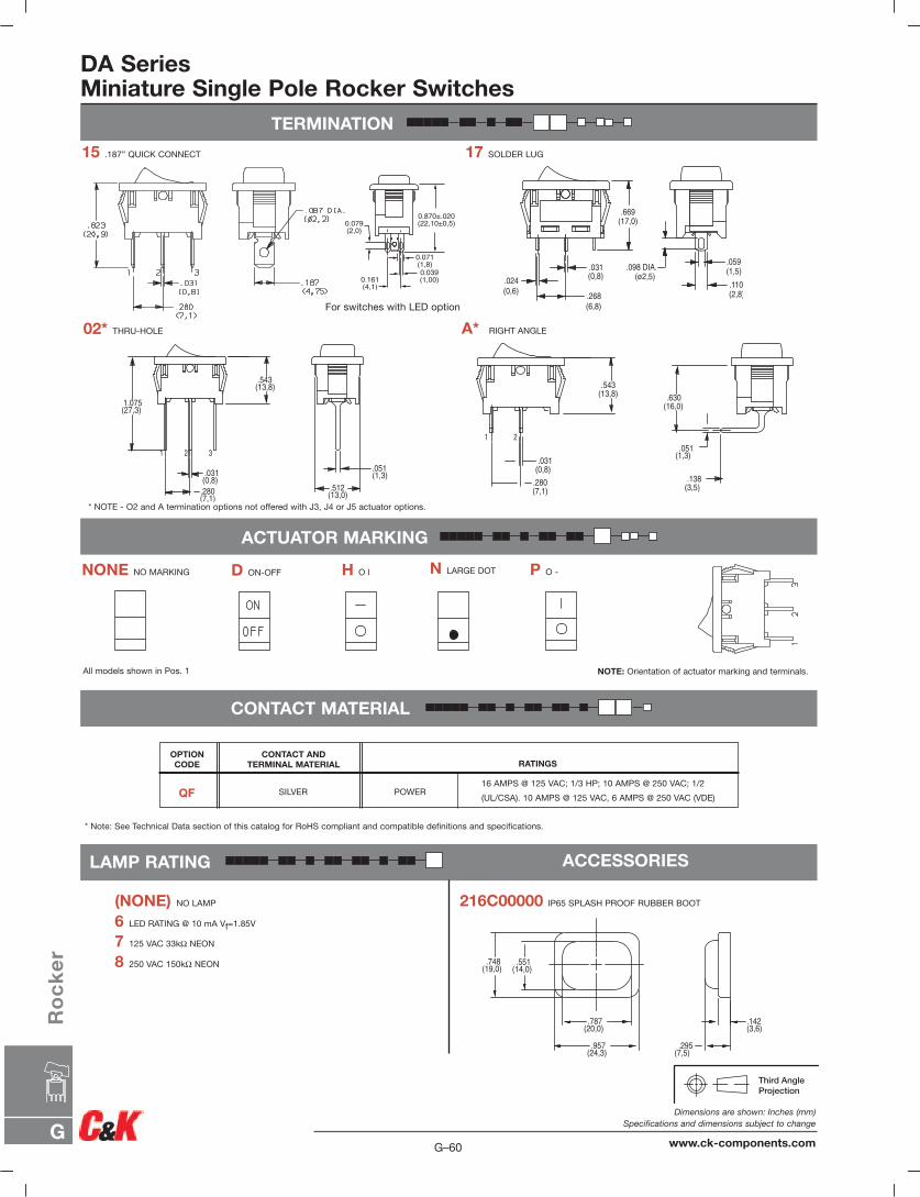
TERMINATION
15 .187” QUICK CONNECT 17 SOLDER LUG
ACTUATOR MARKING
CONTACT MATERIAL
NONE NO MARKING D ON-OFF H O l N LARGE DOT P O -
NOTE: Orientation of actuator marking and terminals.All models shown in Pos. 1
DA SeriesMiniature Single Pole Rocker Switches
02* THRU-HOLE A* RIGHT ANGLE
LAMP RATING
(NONE) NO LAMP
6 LED RATING @ 10 mA Vf=1.85V
7 125 VAC 33kΩ NEON
8 250 VAC 150kΩ NEON
ACCESSORIES
.551(14,0)
.748(19,0)
.787(20,0)
.957(24,3)
.142(3,6)
.295(7,5)
216C00000 IP65 SPLASH PROOF RUBBER BOOT
* Note: See Technical Data section of this catalog for RoHS compliant and compatible definitions and specifications.
16 AMPS @ 125 VAC; 1/3 HP; 10 AMPS @ 250 VAC; 1/2
(UL/CSA). 10 AMPS @ 125 VAC, 6 AMPS @ 250 VAC (VDE)
RATINGSCONTACT AND
TERMINAL MATERIAL
SILVER POWER
OPTION CODE
QF
0.079(2,0)
0.161(4,1)
0.071(1,8)0.039(1,00)
0.870±.020(22,10±0,5)
For switches with LED option
* NOTE - O2 and A termination options not offered with J3, J4 or J5 actuator options.
G–60
Dimensions are shown: Inches (mm)Specifications and dimensions subject to change
www.ck-components.comG
Ro
ck
er
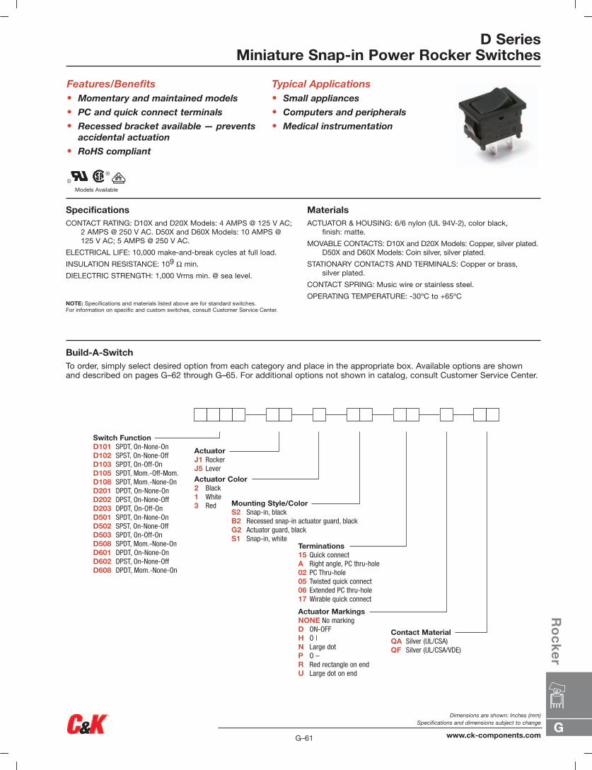
D SeriesMiniature Snap-in Power Rocker Switches
Features/Benefits• Momentary and maintained models
• PC and quick connect terminals
• Recessed bracket available — preventsaccidental actuation
• RoHS compliant
Typical Applications• Small appliances
• Computers and peripherals
• Medical instrumentation
SpecificationsCONTACT RATING: D10X and D20X Models: 4 AMPS @ 125 V AC;
2 AMPS @ 250 V AC. D50X and D60X Models: 10 AMPS @125 V AC; 5 AMPS @ 250 V AC.
ELECTRICAL LIFE: 10,000 make-and-break cycles at full load.
INSULATION RESISTANCE: 109 Ω min.
DIELECTRIC STRENGTH: 1,000 Vrms min. @ sea level.
NOTE: Specifications and materials listed above are for standard switches.For information on specific and custom switches, consult Customer Service Center.
MaterialsACTUATOR & HOUSING: 6/6 nylon (UL 94V-2), color black,
finish: matte.
MOVABLE CONTACTS: D10X and D20X Models: Copper, silver plated.D50X and D60X Models: Coin silver, silver plated.
STATIONARY CONTACTS AND TERMINALS: Copper or brass,silver plated.
CONTACT SPRING: Music wire or stainless steel.
OPERATING TEMPERATURE: -30ºC to +65ºC
Build-A-SwitchTo order, simply select desired option from each category and place in the appropriate box. Available options are shown and described on pages G–62 through G–65. For additional options not shown in catalog, consult Customer Service Center.
Switch FunctionD101 SPDT, On-None-OnD102 SPST, On-None-OffD103 SPDT, On-Off-OnD105 SPDT, Mom.-Off-Mom.D108 SPDT, Mom.-None-OnD201 DPDT, On-None-OnD202 DPST, On-None-OffD203 DPDT, On-Off-OnD501 SPDT, On-None-OnD502 SPST, On-None-OffD503 SPDT, On-Off-OnD508 SPDT, Mom.-None-OnD601 DPDT, On-None-OnD602 DPST, On-None-OffD608 DPDT, Mom.-None-On
ActuatorJ1 RockerJ5 Lever
Actuator Color2 Black1 White 3 Red Mounting Style/Color
S2 Snap-in, blackB2 Recessed snap-in actuator guard, black G2 Actuator guard, black S1 Snap-in, white
Contact MaterialQA Silver (UL/CSA)QF Silver (UL/CSA/VDE)
Terminations15 Quick connectA Right angle, PC thru-hole02 PC Thru-hole05 Twisted quick connect06 Extended PC thru-hole17 Wirable quick connect
Actuator MarkingsNONE No markingD ON-OFFH O |N Large dotP O –R Red rectangle on endU Large dot on end
Models Available
G
Ro
ck
er
G–61
Dimensions are shown: Inches (mm)Specifications and dimensions subject to change
www.ck-components.com
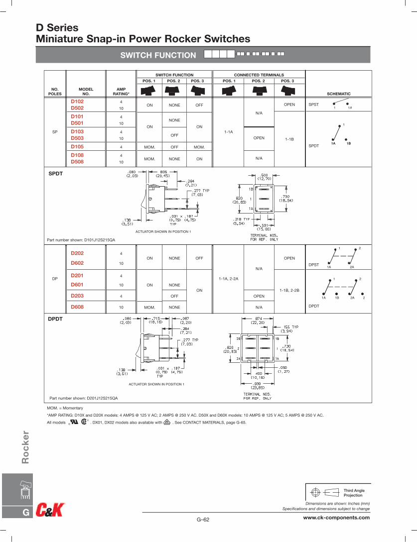
D SeriesMiniature Snap-in Power Rocker Switches
SWITCH FUNCTION
ACTUATOR SHOWN IN POSITION 1
DPST
DPDT
OPEN
1-1B, 2-2B
N/A
OPEN
N/A
1-1A, 2-2A
OFF
ON
NONE
NONE
OFF
NONE
ON
ON
MOM.
4
10
4
10
4
10
D202
D602
D201
D601
D203
D608
DP
SPST
SPDT
OPEN
1-1B
N/A
OPEN
N/A
1-1A
OFF
ON
MOM.
ON
NONE
NONE
OFF
OFF
NONE
ON
ON
MOM.
MOM.
4
10
4
10
4
10
4
4
10
D102 D502
D101 D501
D103 D503
D105
D108D508
SP
SCHEMATIC
CONNECTED TERMINALS
POS. 1 POS. 2 POS. 3
SWITCH FUNCTION
POS. 1 POS. 2 POS. 3
AMPRATING*
MODEL NO.
NO.POLES
DPDT
SPDT
Part number shown: D101J12S215QA
Part number shown: D201J12S215QA
MOM. = Momentary
*AMP RATING: D10X and D20X models: 4 AMPS @ 125 V AC; 2 AMPS @ 250 V AC. D50X and D60X models: 10 AMPS @ 125 V AC; 5 AMPS @ 250 V AC.
All models . DX01, DX02 models also available with . See CONTACT MATERIALS, page G-65.
1 1A
1
1A 1B1A 1B
1 2
1A 2A
1 2
1A 1B 2A 2
G–62
Dimensions are shown: Inches (mm)Specifications and dimensions subject to change
www.ck-components.comG
Ro
ck
er

D SeriesMiniature Snap-in Power Rocker Switches
ACTUATOR
MOUNTING STYLE/COLOR
SP
DP
PANEL MOUNTING
SP MODELS'S' & 'G2' mounting styles
DP MODELS'S' mounting style
SP MODELS'B2' mounting style
2 BLACK
1 WHITE
3 RED
ACTUATORCOLOR
OPTION CODE
NOTE: Actuator finish: matte.Other colors available, consultCustomer Service Center.
NOTE: Frame finish on housing: matte.Other colors available, consult CustomerService Center.
2 (STD.) BLACK
1 WHITE
HOUSING COLOR
OPTION CODE
J1 ROCKER
S SNAP-IN B2 RECESSED SNAP-IN ACTUATOR GUARD, BLACK
G2 ACTUATOR GUARD, BLACK
J5 LEVER
NOTE: Vertical mount, SP models only.
NOTE: Vertical mount, SP models only.
NOTE: Blank insert available for SP models only, see page G-65.
‘J5’ actuator available only with DPmodels D201, D202, D601 and D602.
ACTUATOR COLOR
ACTUATOR
NEW!
PANEL THICKNESS
.030–.049(0,76) (1,24)
.049–.079(1,24) (2,01)
.079–.118(2,01) (3,00)
.756(19,20)
.764(19,41)
.780(19,81)
.764(19,41)
.780(19,81)
n/a
1.068(27,13)
1.076(27,33)
1.092(27,74)
DIM ‘A’SP & DP MODELS
‘S’ MOUNTING STYLE
DIM ‘A’WITH ‘G2” OPTIONSP MODELS ONLY
DIM ‘A’SP MODELS
‘B’ MOUNTING STYLE
G
Ro
ck
er
G–63
Dimensions are shown: Inches (mm)Specifications and dimensions subject to change
www.ck-components.com
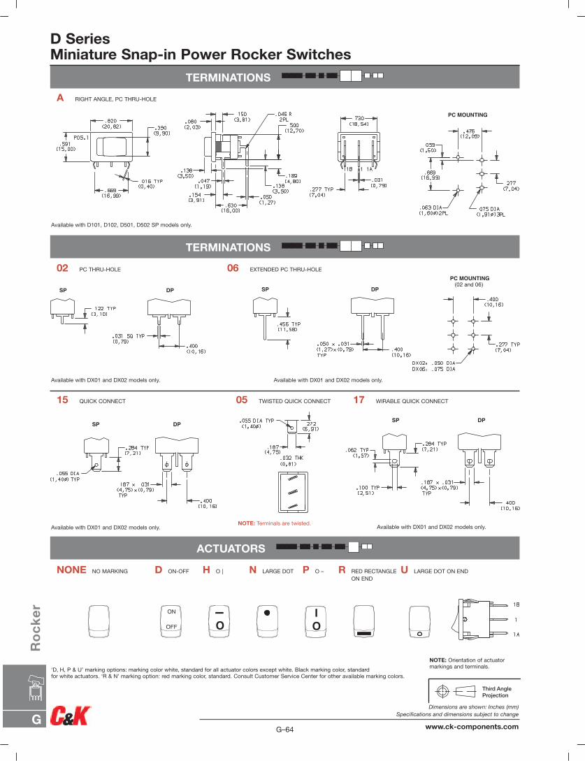
D SeriesMiniature Snap-in Power Rocker Switches
TERMINATIONS
TERMINATIONS
ACTUATORS
ON
OFF O
I
OI
SP DP SP DP
PC MOUNTING (02 and 06)
SP DPSP DP
PC MOUNTING
A RIGHT ANGLE, PC THRU-HOLE
02 PC THRU-HOLE
15 QUICK CONNECT
06 EXTENDED PC THRU-HOLE
05 TWISTED QUICK CONNECT 17 WIRABLE QUICK CONNECT
NONE NO MARKING D ON-OFF H O | N LARGE DOT U LARGE DOT ON ENDP O – R RED RECTANGLE ON END
Available with D101, D102, D501, D502 SP models only.
Available with DX01 and DX02 models only.
Available with DX01 and DX02 models only.
‘D, H, P & U’ marking options: marking color white, standard for all actuator colors except white. Black marking color, standardfor white actuators. ‘R & N’ marking option: red marking color, standard. Consult Customer Service Center for other available marking colors.
NOTE: Terminals are twisted. Available with DX01 and DX02 models only.
NOTE: Orientation of actuatormarkings and terminals.
Available with DX01 and DX02 models only.
G–64
Dimensions are shown: Inches (mm)Specifications and dimensions subject to change
www.ck-components.comG
Ro
ck
er
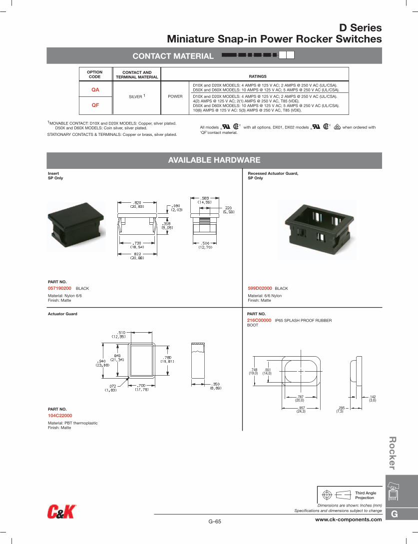
D SeriesMiniature Snap-in Power Rocker Switches
CONTACT MATERIAL
1MOVABLE CONTACT: D10X and D20X MODELS: Copper, silver plated.D50X and D60X MODELS: Coin silver, silver plated.
STATIONARY CONTACTS & TERMINALS: Copper or brass, silver plated.
All models with all options. DX01, DX02 models when ordered with‘QF’contact material.
AVAILABLE HARDWARE
InsertSP Only
PART NO.
057190200 BLACK
Material: Nylon 6/6Finish: Matte
Recessed Actuator Guard,SP Only
599D02000 BLACK
Material: 6/6 NylonFinish: Matte
PART NO.
216C00000 IP65 SPLASH PROOF RUBBERBOOT
Actuator Guard
PART NO.
104C22000
Material: PBT thermoplasticFinish: Matte
OPTION CODE
QA
QF
CONTACT ANDTERMINAL MATERIAL
POWERSILVER 1
RATINGS
D10X and D20X MODELS: 4 AMPS @ 125 V AC; 2 AMPS @ 250 V AC (UL/CSA).D50X and D60X MODELS: 10 AMPS @ 125 V AC; 5 AMPS @ 250 V AC (UL/CSA).
D10X and D20X MODELS: 4 AMPS @ 125 V AC; 2 AMPS @ 250 V AC (UL/CSA).4(2) AMPS @ 125 V AC; 2(1) AMPS @ 250 V AC, T85 (VDE).D50X and D60X MODELS: 10 AMPS @ 125 V AC; 5 AMPS @ 250 V AC (UL/CSA).10(6) AMPS @ 125 V AC: 5(3) AMPS @ 250 V AC, T85 (VDE).
.551(14,0)
.748(19,0)
.787(20,0)
.957(24,3)
.142(3,6)
.295(7,5)
G
Ro
ck
er
G–65
Dimensions are shown: Inches (mm)Specifications and dimensions subject to change
www.ck-components.com
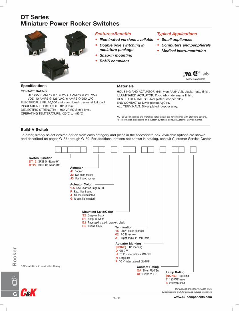
DT SeriesMiniature Power Rocker Switches
Build-A-SwitchTo order, simply select desired option from each category and place in the appropriate box. Available options are shownand described on pages G–67 through G–69. For additional options not shown in catalog, consult Customer Service Center.
SpecificationsCONTACT RATING:
UL/CSA: 8 AMPS @ 125 VAC, 4 AMPS @ 250 VACVDE: 10 AMPS @ 125 VAC, 6 AMPS @ 250 VAC.
ELECTRICAL LIFE: 10,000 make and break cycles at full load.INSULATION RESISTANCE: 108 Ω min.DIELECTRIC STRENGTH: 1,500 VRMS @ sea level.OPERATING TEMTERATURE: -20ºC to +85ºC
Features/Benefits• Illuminated versions available
• Double pole switching inminiature package
• Snap-in mounting
• RoHS compliant
MaterialsHOUSING AND ACTUATOR: 6/6 nylon (UL94V-2), black, matte finish.ILLUMINATED ACTUATOR: Polycarbonate, matte finish.CENTER CONTACTS: Silver plated, copper alloy.END CONTACTS: Silver plated AgCdo.ALL TERMINALS: Silver plated, copper alloy.
NOTE: Specifications and materials listed above are for switches with standard options. For information on specific and custom switches, consult Customer Service Center.
Typical Applications• Small appliances
• Computers and peripherals
• Medical instrumentation
Lamp Rating(NONE) No lamp7 125 VAC neon8 250 VAC neon
ActuatorJ1 RockerJ2 Two-tone rockerJ3 Illuminated rocker
Switch FunctionDT12 SPST On-None-OffDT22 DPST On-None-Off
Actuator Color1-5 See Chart on Page G-68R Red, illuminatedA Amber, illuminatedG Green, illuminated
Contact RatingQA Silver (UL/CSA)QF Silver (VDE)*
Mounting Style/ColorS2 Snap-in, blackS1 Snap-in, whiteB2 Recessed snap-in bracket, blackG2 Guard, black
Actuator Marking(NONE) No markingD ON-OFFH ”O l” - international ON-OFFN Large dotP ”O -” international ON-OFF
Termination15 .187” quick connect02 PC Thru-holeA Right angle, PC thru-hole
* QF available with termination 15 only.
Models Available
G–66
Dimensions are shown: Inches (mm)Specifications and dimensions subject to change
www.ck-components.comG
Ro
ck
er

SWITCH FUNCTION
DT SeriesMiniature Power Rocker Switches
ACTUATOR
J1 ROCKER
J3 ILLUMINATED ROCKER
J2 TWO-TONE ROCKER
SWITCH FUNCTION CONNECTED TERMINALS
C&K marking on opposite side C&K marking on opposite sideNO.
POLES MODEL NO. SCHEMATIC
DP
SP ON OFF
ON OFF
DT12
DT22
2-1 OPEN
OR
For IlluminatedVersions
1 2
OR
For IlluminatedVersions
a1 a2
b1 b2
1a 2a
1b 2b
POS 1 POS 3 POS 1 POS 3
G
Ro
ck
er
G–67
Dimensions are shown: Inches (mm)Specifications and dimensions subject to change
www.ck-components.com
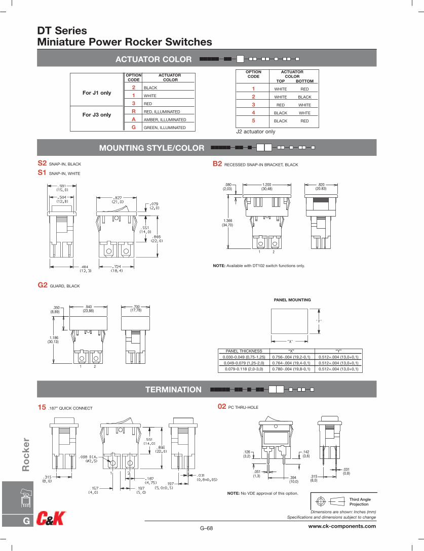
ACTUATOR COLOR
DT SeriesMiniature Power Rocker Switches
MOUNTING STYLE/COLOR
TERMINATION
PANEL MOUNTING
PANEL THICKNESS “X” “Y”
0.030-0.049 (0,75-1,25) 0.756-.004 (19,2-0,1) 0.512+.004 (13,0+0,1)
0.049-0.079 (1,25-2,0) 0.764-.004 (19,4-0,1) 0.512+.004 (13,0+0,1)
0.079-0.118 (2,0-3,0) 0.780-.004 (19,8-0,1) 0.512+.004 (13,0+0,1)
S2 SNAP-IN, BLACK
S1 SNAP-IN, WHITE
B2 RECESSED SNAP-IN BRACKET, BLACK
G2 GUARD, BLACK
NOTE: Available with DT102 switch functions only.
15 .187” QUICK CONNECT 02 PC THRU-HOLE
NOTE: No VDE approval of this option.
1 2
.820(20.83)
1.200(30,48)
.080(2,03)
1.366(34,70)
1 2
.700(17,78)
.940(23,88)
.350(8,89)
1.186(30,13)
.315(8,0)
.031(0,8).051
(1,3) .394(10,0)
.126(3,2)
.142(3,6)
OPTION ACTUATORCODE COLOR
TOP BOTTOM
1 WHITE RED
2 WHITE BLACK
3 RED WHITE
4 BLACK WHTE
5 BLACK RED
J2 actuator only
OPTION ACTUATORCODE COLOR
2 BLACK
1 WHITE
3 RED
R RED, ILLUMINATED
A AMBER, ILLUMINATED
G GREEN, ILLUMINATED
For J1 only
For J3 only
G–68
Dimensions are shown: Inches (mm)Specifications and dimensions subject to change
www.ck-components.comG
Ro
ck
er
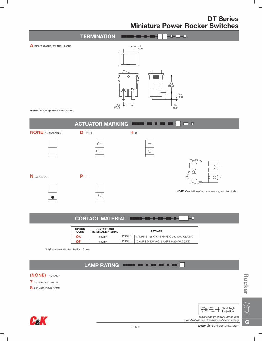
OPTIONCODE
CONTACT AND TERMINAL MATERIAL RATINGS
TERMINATION
DT SeriesMiniature Power Rocker Switches
ACTUATOR MARKING
CONTACT MATERIAL
LAMP RATING
(NONE) NO LAMP
7 125 VAC 33kΩ NEON
8 250 VAC 150kΩ NEON
NONE NO MARKING D ON-OFF H O-l
N LARGE DOT P O –
NOTE: Orientation of actuator marking and terminals.
A RIGHT ANGLE, PC THRU-HOLE
NOTE: No VDE approval of this option.
.394(10,0)
.708(18,0)
.256(6,5)
.049(1,3)
.031(0,8)
*1 QF available with termination 15 only.
QA
QF
SILVER
SILVER
POWER
POWER
8 AMPS @ 125 VAC; 4 AMPS @ 250 VAC (UL/CSA)
10 AMPS @ 125 VAC; 6 AMPS @ 250 VAC (VDE)
G
Ro
ck
er
G–69
Dimensions are shown: Inches (mm)Specifications and dimensions subject to change
www.ck-components.com
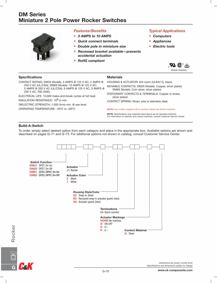
G–70
Dimensions are shown: Inches (mm)Specifications and dimensions subject to change
www.ck-components.comG
Ro
ck
er
DM SeriesMiniature 2 Pole Power Rocker Switches
Models Available
Features/Benefits• 3 AMPS to 10 AMPS
• Quick connect terminals
• Double pole in miniature size
• Recessed bracket available—preventsaccidental actuation
• RoHS compliant
Typical Applications• Computers
• Appliances
• Electric tools
SpecificationsCONTACT RATING: DM2X Models: 3 AMPS @ 125 V AC; 2 AMPS @
250 V AC (UL/CSA). DM6X Models: 10 AMPS @ 125 V AC;5 AMPS @ 250 V AC (UL/CSA). 6 AMPS @ 125 V AC, 3 AMPS @250 V AC, T85 (VDE).
ELECTRICAL LIFE: 10,000 make-and-break cycles at full load.
INSULATION RESISTANCE: 109 Ω min.
DIELECTRIC STRENGTH: 1,000 Vrms min. @ sea level.
OPERATING TEMPERATURE: -20ºC to +85ºC
MaterialsHOUSING & ACTUATOR: 6/6 nylon (UL94V-2), black.
MOVABLE CONTACTS: DM2X Models: Copper, silver plated.DM6X Models: Coin silver, silver plated.
STATIONARY CONTACTS & TERMINALS: Copper or brass,silver plated.
CONTACT SPRING: Music wire or stainless steel.
NOTE: Any models supplied with Q contact material are RoHS compliant.
NOTE: Specifications and materials listed above are for standard switches.For information on specific and custom switches, consult Customer Service Center.
Build-A-SwitchTo order, simply select desired option from each category and place in the appropriate box. Available options are shown anddescribed on pages G–71 and G–73. For additional options not shown in catalog, consult Customer Service Center.
Switch FunctionDM21 DPDT, On-OnDM22 DPST, On-OffDM61 (STD.) DPDT, On-OnDM62 (STD.) DPST, On-Off
ActuatorJ1 Rocker
Actuator Color2 Black1 White
Housing Style/ColorS2 Snap-in, blackB2 Recessed snap-in actuator guard, blackG2 Actuator guard, black
Contact MaterialQ Silver
Terminations05 Quick connect
Actuator MarkingsNONE No markingD ON-OFFH O |P O –
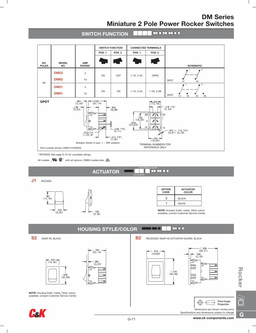
G
Ro
ck
er
G–71
Dimensions are shown: Inches (mm)Specifications and dimensions subject to change
www.ck-components.com
DM SeriesMiniature 2 Pole Power Rocker Switches
SWITCH FUNCTION
ACTUATOR
HOUSING STYLE/COLOR
Actuator shown in pos. 1 – 'ON' position. TERMINAL NUMBERS FORREFERENCE ONLY
2B 1B
DPST
DPDT
OPEN
1-1B, 2-2B
1-1A, 2-2A
1-1A, 2-2A
OFF
ON
ON
ON
3
10
3
10
DM22
DM62
DM21
DM61
DP
SCHEMATIC
CONNECTED TERMINALS
POS. 1 POS. 2
SWITCH FUNCTION
POS. 1 POS. 2
AMPRATING*
MODEL NO.
NO.POLES
DPDT
1 2
1A 2A
1A
1
1B 2A 2B
2
Part number shown: DM61J12S205Q
* RATINGS: See page G-72 for complete ratings.
All models with all options. DM6X models also
S2 SNAP-IN, BLACK
J1 ROCKER
B2 RECESSED SNAP-IN ACTUATOR GUARD, BLACK
ACTUATOR COLOR
ACTUATOR
NOTE: Actuator finish: matte. Other colorsavailable, consult Customer Service Center.
NOTE: Housing finish: matte. Other colorsavailable, consult Customer Service Center.
2 BLACK
1 WHITE
ACTUATORCOLOR
OPTION CODE
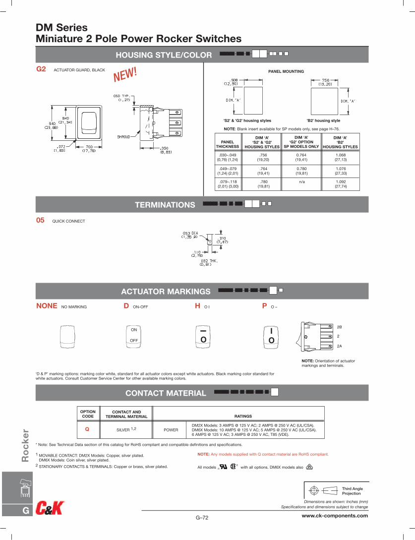
DM SeriesMiniature 2 Pole Power Rocker Switches
HOUSING STYLE/COLOR
TERMINATIONS
ACTUATOR MARKINGS
CONTACT MATERIAL
ON
OFF O
I
OI 2B
2
2A
PANEL MOUNTING
'B2' housing style'S2' & 'G2' housing styles
1 MOVABLE CONTACT: DM2X Models: Copper, silver plated.DM6X Models: Coin silver, silver plated.
2 STATIONARY CONTACTS & TERMINALS: Copper or brass, silver plated.
‘D & P’ marking options: marking color white, standard for all actuator colors except white actuators. Black marking color standard forwhite actuators. Consult Customer Service Center for other available marking colors.
NOTE: Orientation of actuatormarkings and terminals.
NOTE: Blank insert available for SP models only, see page H–76.
NOTE: Any models supplied with Q contact material are RoHS compliant.
All models with all options. DM6X models also
* Note: See Technical Data section of this catalog for RoHS compliant and compatible definitions and specifications.
05 QUICK CONNECT
NONE NO MARKING D ON-OFF H O I P O –
G2 ACTUATOR GUARD, BLACK
NEW!
OPTION CODE
CONTACT ANDTERMINAL MATERIAL RATINGS
Q SILVER 1,2 POWERDM2X Models: 3 AMPS @ 125 V AC; 2 AMPS @ 250 V AC (UL/CSA).DM6X Models: 10 AMPS @ 125 V AC; 5 AMPS @ 250 V AC (UL/CSA).6 AMPS @ 125 V AC; 3 AMPS @ 250 V AC, T85 (VDE).
PANEL THICKNESS
.030–.049(0,76) (1,24)
.049–.079(1,24) (2,01)
.079–.118(2,01) (3,00)
.756(19,20)
.764(19,41)
.780(19,81)
0.764(19,41)
0.780(19,81)
n/a
1.068(27,13)
1.076(27,33)
1.092(27,74)
DIM ‘A’‘S2’ & ‘G2’
HOUSING STYLES
DIM ‘A’‘G2’ OPTION
SP MODELS ONLY
DIM ‘A’‘B2’
HOUSING STYLES
G–72
Dimensions are shown: Inches (mm)Specifications and dimensions subject to change
www.ck-components.comG
Ro
ck
er
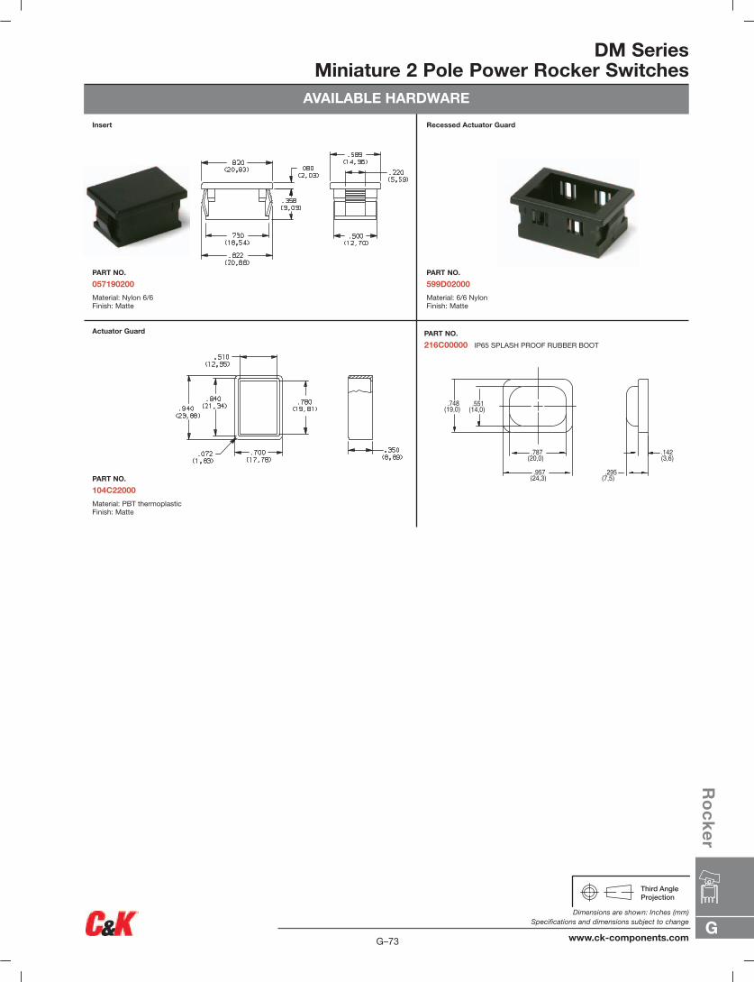
DM SeriesMiniature 2 Pole Power Rocker Switches
AVAILABLE HARDWARE
Insert
PART NO.
057190200
Material: Nylon 6/6Finish: Matte
Recessed Actuator Guard
PART NO.
599D02000
Material: 6/6 NylonFinish: Matte
Actuator Guard
PART NO.
104C22000
Material: PBT thermoplasticFinish: Matte
PART NO.
216C00000 IP65 SPLASH PROOF RUBBER BOOT
.551(14,0)
.748(19,0)
.787(20,0)
.957(24,3)
.142(3,6)
.295(7,5)
G
Ro
ck
er
G–73
Dimensions are shown: Inches (mm)Specifications and dimensions subject to change
www.ck-components.com
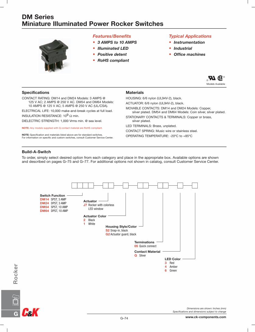
Models Available
DM SeriesMiniature Illuminated Power Rocker Switches
Features/Benefits• 3 AMPS to 10 AMPS
• Illuminated LED
• Positive detent
• RoHS compliant
Typical Applications• Instrumentation
• Industrial
• Office machines
SpecificationsCONTACT RATING: DM14 and DM24 Models: 3 AMPS @
125 V AC; 2 AMPS @ 250 V AC. DM54 and DM64 Models:10 AMPS @ 125 V AC; 5 AMPS @ 250 V AC (UL/CSA).
ELECTRICAL LIFE: 10,000 make-and-break cycles at full load.
INSULATION RESISTANCE: 109 Ω min.
DIELECTRIC STRENGTH: 1,000 Vrms min. @ sea level.
NOTE: Any models supplied with Q contact material are RoHS compliant.
NOTE: Specification and materials listed above are for standard switches.For information on specific and custom switches, consult Customer Service Center.
MaterialsHOUSING: 6/6 nylon (UL94V-2), black.
ACTUATOR: 6/6 nylon (UL94V-2), black.
MOVABLE CONTACTS: DM14 and DM24 Models: Copper,silver plated. DM54 and DM64 Models: Coin silver, silver plated.
STATIONARY CONTACTS & TERMINALS: Copper or brass,silver plated.
LED TERMINALS: Brass, unplated.
CONTACT SPRING: Music wire or stainless steel.
OPERATING TEMPERATURE: -20ºC to +85ºC
Build-A-SwitchTo order, simply select desired option from each category and place in the appropriate box. Available options are shown and described on pages G–75 and G–77. For additional options not shown in catalog, consult Customer Service Center.
Switch FunctionDM14 SPST, 3 AMP DM24 DPST, 3 AMPDM54 SPST, 10 AMPDM64 DPST, 10 AMP
ActuatorJ7 Rocker with colorless
LED window
Actuator Color2 Black1 White
Housing Style/ColorS2 Snap-in, blackG2 Actuator guard, black
Contact MaterialQ Silver
Terminations05 Quick connect
LED Color3 Red4 Amber6 Green
G–74
Dimensions are shown: Inches (mm)Specifications and dimensions subject to change
www.ck-components.comG
Ro
ck
er
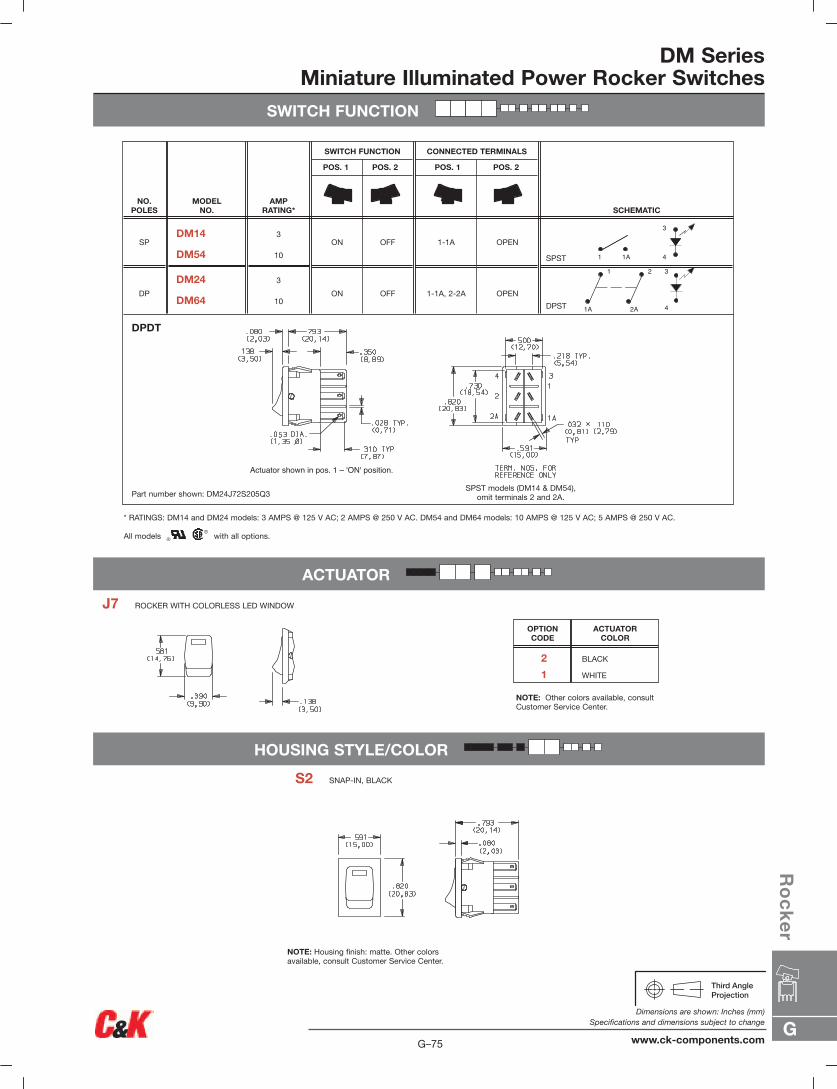
DM SeriesMiniature Illuminated Power Rocker Switches
SWITCH FUNCTION
ACTUATOR
HOUSING STYLE/COLOR
Actuator shown in pos. 1 – 'ON' position.
SPST
DPST
OPEN
OPEN
1-1A
1-1A, 2-2A
OFF
OFF
ON
ON
3
10
3
10
DM14
DM54
DM24
DM64
SP
DP
SCHEMATIC
CONNECTED TERMINALS
POS. 1 POS. 2
SWITCH FUNCTION
POS. 1 POS. 2
AMPRATING*
MODEL NO.
NO.POLES
DPDT
Part number shown: DM24J72S205Q3SPST models (DM14 & DM54),
omit terminals 2 and 2A.
* RATINGS: DM14 and DM24 models: 3 AMPS @ 125 V AC; 2 AMPS @ 250 V AC. DM54 and DM64 models: 10 AMPS @ 125 V AC; 5 AMPS @ 250 V AC.
All models with all options.
S2 SNAP-IN, BLACK
J7 ROCKER WITH COLORLESS LED WINDOW
NOTE: Other colors available, consultCustomer Service Center.
NOTE: Housing finish: matte. Other colorsavailable, consult Customer Service Center.
2 BLACK
1 WHITE
ACTUATORCOLOR
OPTION CODE
1A
1
2A
2 3
4
3
1 1A 4
G
Ro
ck
er
G–75
Dimensions are shown: Inches (mm)Specifications and dimensions subject to change
www.ck-components.com
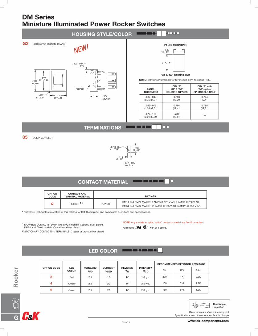
DM SeriesMiniature Illuminated Power Rocker Switches
HOUSING STYLE/COLOR
PANEL MOUNTING
'S2' & 'G2' housing style
TERMINATIONS
CONTACT MATERIAL
LED COLOR
150 510 1.2K2.0 typ.4V202.1Green6
150 510 1.2K2.5 typ.4V202.2Amber4
270 1K 2.2K1.6 typ.4V102.1Red3
RECOMMENDED RESISTOR @ VOLTAGE
5V 12V 24VINTENSITY
MCD
REVERSEVR
CURRENTLLED
FORWARDVFD
LEDCOLOR
OPTION CODE
1 MOVABLE CONTACTS: DM14 and DM24 models: Copper, silver plated.DM54 and DM64 models: Coin silver, silver plated.
2 STATIONARY CONTACTS & TERMINALS: Copper or brass, silver plated.
NOTE: Blank insert available for SP models only, see page H-80.
NOTE: Any models supplied with Q contact material are RoHS compliant.
All models with all options.
* Note: See Technical Data section of this catalog for RoHS compliant and compatible definitions and specifications.
05 QUICK CONNECT
G2 ACTUATOR GUARD, BLACK
n/a.780
(19,81).079–.118
(2,01) (3,00)
0.780(19,81)
0.764(19,41)
.049–.079(1,24) (2,01)
0.764(19,41)
0.756(19,20)
.030–.049(0,76) (1,24)
DIM ‘A’ with‘G2’ option
SP MODELS ONLY
DIM ‘A’‘S2’ & ‘G2’
HOUSING STYLESPANEL
THICKNESS
NEW!
DM14 and DM24 Models: 3 AMPS @ 125 V AC; 2 AMPS @ 250 V AC.
DM54 and DM64 Models: 10 AMPS @ 125 V AC; 5 AMPS @ 250 V AC.
RATINGSCONTACT AND
TERMINAL MATERIAL
SILVER 1,2 POWER
OPTION CODE
Q
G–76
Dimensions are shown: Inches (mm)Specifications and dimensions subject to change
www.ck-components.comG
Ro
ck
er
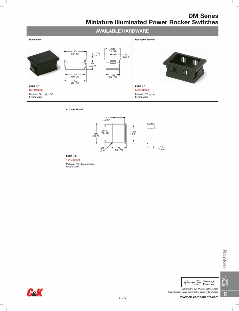
DM SeriesMiniature Illuminated Power Rocker Switches
AVAILABLE HARDWARE
Blank Insert
PART NO.
057190200
Material: Zinc nylon 6/6Finish: Matte
Recessed Bracket
PART NO.
599D02000
Material: 6/6 NylonFinish: Matte
Actuator Guard
PART NO.
104C22000
Material: PBT thermoplasticFinish: Matte
G
Ro
ck
er
G–77
Dimensions are shown: Inches (mm)Specifications and dimensions subject to change
www.ck-components.com
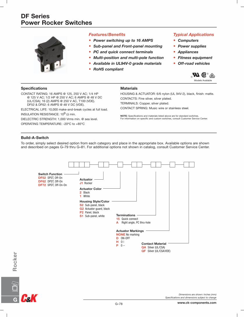
Models Available
DF SeriesPower Rocker Switches
Features/Benefits• Power switching up to 16 AMPS
• Sub-panel and Front-panel mounting
• PC and quick connect terminals
• Multi-position and multi-pole function
• Available in UL94V-0 grade materials
• RoHS compliant
Typical Applications• Computers
• Power supplies
• Appliances
• Fitness equipment
• Off-road vehicles
SpecificationsCONTACT RATING: 16 AMPS @ 125, 250 V AC; 1/4 HP
@ 125 V AC; 1/2 HP @ 250 V AC; 6 AMPS @ 48 V DC(UL/CSA); 16 (2) AMPS @ 250 V AC, T100 (VDE).DF52 & DF62: 6 AMPS @ 48 V DC (VDE).
ELECTRICAL LIFE: 10,000 make-and-break cycles at full load.
INSULATION RESISTANCE: 109 Ω min.
DIELECTRIC STRENGTH: 1,000 Vrms min. @ sea level.
OPERATING TEMPERATURE: -20ºC to +85ºC
MaterialsHOUSING & ACTUATOR: 6/6 nylon (UL 94V-2), black, finish: matte.
CONTACTS: Fine silver, silver plated.
TERMINALS: Copper, silver plated.
CONTACT SPRING: Music wire or stainless steel.
NOTE: Specifications and materials listed above are for standard switches.For information on specific and custom switches, consult Customer Service Center.
Build-A-SwitchTo order, simply select desired option from each category and place in the appropriate box. Available options are shown and described on pages G–79 thru G–81. For additional options not shown in catalog, consult Customer Service Center.
Switch FunctionDF52 SPST, Off-OnDF62 DPST, Off-OnDF72 SPDT, Off-On-On
ActuatorJ1 Rocker
Actuator Color2 Black1 White
Housing Style/ColorS2 Sub-panel, blackG2 Actuator guard, blackP2 Panel, blackS1 Sub-panel, white
Contact MaterialQA Silver (UL/CSA)QF Silver (UL/CSA/VDE)
Terminations15 Quick connectA Right angle, PC thru-hole
Actuator MarkingsNONE No markingD ON-OFFH O |P 0 –
G–78
Dimensions are shown: Inches (mm)Specifications and dimensions subject to change
www.ck-components.comG
Ro
ck
er
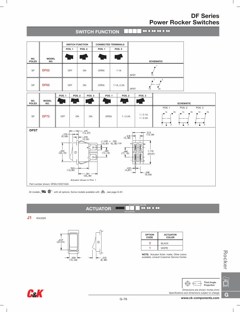
DF SeriesPower Rocker Switches
SWITCH FUNCTION
ACTUATOR
SPST
DPST
1-1A
1-1A, 2-2A
OPEN
OPEN
ON
ON
OFF
OFF
DF52
DF62
SP
DP
SCHEMATIC
CONNECTED TERMINALS
POS. 1 POS. 2
SWITCH FUNCTION
POS. 1 POS. 2
MODEL NO.
NO.POLES
1A
1
1A
1
2A
2
NOTE: Actuator finish: matte. Other colorsavailable, consult Customer Service Center.
2 BLACK
1 WHITE
ACTUATORCOLOR
OPTION CODE
J1 ROCKER
ACTUATOR COLOR
ACTUATOR
All models with all options. Some models available with , see page G–81.
1 / 2-1A
1 / 2-2A1 / 2-2AOPENOFF ON ONDF72SP
SCHEMATIC
POS. 1 POS. 2 POS. 3POS. 1 POS. 2 POS. 3
MODELNO.
NO.POLES
DPST
Part number shown: DF62J12S215QA
1.176(29,87)
1
1a
2
2a
1
1a
2
2a
1
1a
2
2a
POS. 1 POS. 2 POS. 3
G
Ro
ck
er
G–79
Dimensions are shown: Inches (mm)Specifications and dimensions subject to change
www.ck-components.com
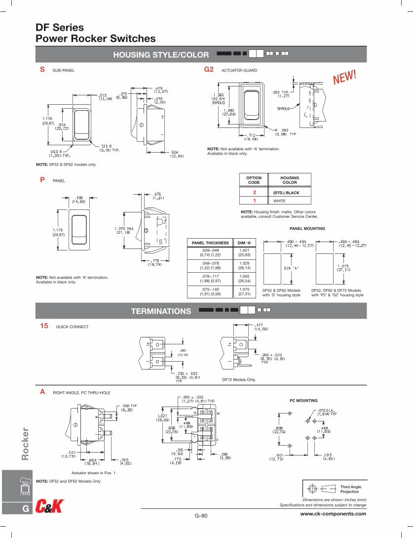
DF SeriesPower Rocker Switches
HOUSING STYLE/COLOR
TERMINATIONS
1.176(29,87)
PANEL MOUNTING
1.176(29,87)
.480(12,19)
DF72 Models Only
PC MOUNTING
S SUB-PANEL
P PANEL
A RIGHT ANGLE, PC THRU-HOLE
15 QUICK CONNECT
G2 ACTUATOR GUARD
NOTE: DF52 & DF62 models only.
NOTE: Not available with ‘A’ termination.Available in black only.
NOTE: DF52 and DF62 Models Only
NOTE: Not available with ‘A’ termination.Available in black only.
NOTE: Housing finish: matte. Other colorsavailable, consult Customer Service Center.
DF52 & DF62 Modelswith ‘S’ housing style
DF52, DF62 & DF72 Modelswith ‘P2’ & ‘G2’ housing style
2 (STD.) BLACK
1 WHITE
HOUSINGCOLOR
OPTION CODE
1.075(27,31)
.075–.140(1,91) (3,56)
1.045(26,54)
.078–.117(1,98) (2,97)
1.029(26,14)
.048–.078(1,22) (1,98)
1.021(25,93)
.029–.048(0,74) (1,22)
DIM ‘A’PANEL THICKNESS
NEW!
G–80
Dimensions are shown: Inches (mm)Specifications and dimensions subject to change
www.ck-components.comG
Ro
ck
er
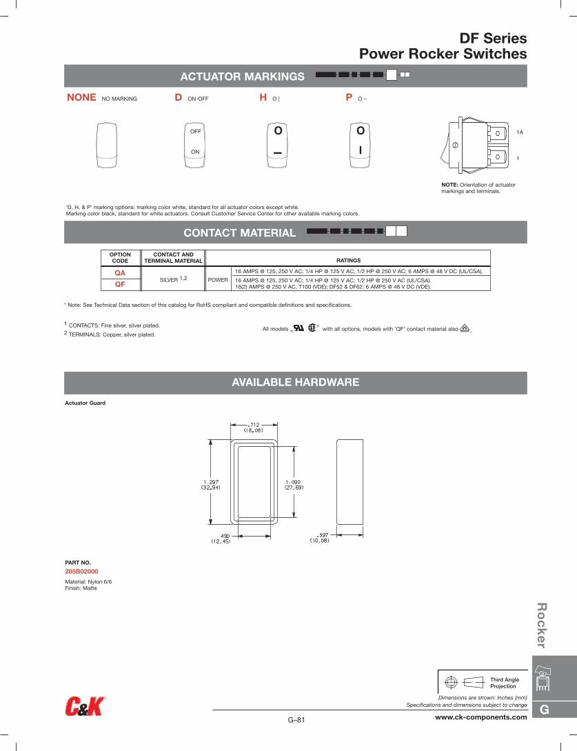
DF SeriesPower Rocker Switches
ACTUATOR MARKINGS
CONTACT MATERIAL
AVAILABLE HARDWARE
ON
OFF O
I
OI
1A
1
OII I
‘D, H, & P’ marking options: marking color white, standard for all actuator colors except white.Marking color black, standard for white actuators. Consult Customer Service Center for other available marking colors.
NOTE: Orientation of actuatormarkings and terminals.
NONE NO MARKING D ON-OFF H O | P O –
1 CONTACTS: Fine silver, silver plated.2 TERMINALS: Copper, silver plated.
All models with all options, models with ‘QF’ contact material also .
* Note: See Technical Data section of this catalog for RoHS compliant and compatible definitions and specifications.
Actuator Guard
PART NO.
285B02000
Material: Nylon 6/6Finish: Matte
16 AMPS @ 125, 250 V AC; 1/4 HP @ 125 V AC; 1/2 HP @ 250 V AC; 6 AMPS @ 48 V DC (UL/CSA).
16 AMPS @ 125, 250 V AC; 1/4 HP @ 125 V AC; 1/2 HP @ 250 V AC (UL/CSA).16(2) AMPS @ 250 V AC, T100 (VDE); DF52 & DF62: 6 AMPS @ 48 V DC (VDE).
RATINGSCONTACT AND
TERMINAL MATERIAL
SILVER 1,2 POWER
OPTION CODE
QA
QF
G
Ro
ck
er
G–81
Dimensions are shown: Inches (mm)Specifications and dimensions subject to change
www.ck-components.com
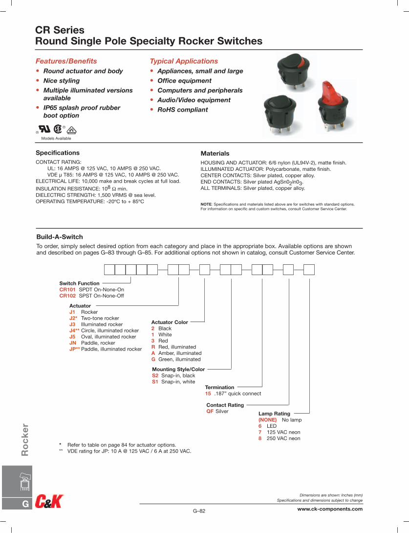
CR SeriesRound Single Pole Specialty Rocker Switches
Build-A-SwitchTo order, simply select desired option from each category and place in the appropriate box. Available options are shownand described on pages G–83 through G–85. For additional options not shown in catalog, consult Customer Service Center.
SpecificationsCONTACT RATING:
UL: 16 AMPS @ 125 VAC, 10 AMPS @ 250 VAC.VDE µ T85: 16 AMPS @ 125 VAC, 10 AMPS @ 250 VAC.
ELECTRICAL LIFE: 10,000 make and break cycles at full load.
INSULATION RESISTANCE: 108 Ω min.DIELECTRIC STRENGTH: 1,500 VRMS @ sea level.OPERATING TEMPERATURE: -20ºC to + 85ºC
Features/Benefits• Round actuator and body
• Nice styling
• Multiple illuminated versionsavailable
• IP65 splash proof rubber boot option
MaterialsHOUSING AND ACTUATOR: 6/6 nylon (UL94V-2), matte finish.ILLUMINATED ACTUATOR: Polycarbonate, matte finish.CENTER CONTACTS: Silver plated, copper alloy.END CONTACTS: Silver plated AgSn02ln03.ALL TERMINALS: Silver plated, copper alloy.
NOTE: Specifications and materials listed above are for switches with standard options. For information on specific and custom switches, consult Customer Service Center.
Typical Applications• Appliances, small and large
• Office equipment
• Computers and peripherals
• Audio/Video equipment
• RoHS compliant
Lamp Rating(NONE) No lamp6 LED7 125 VAC neon8 250 VAC neon
Mounting Style/ColorS2 Snap-in, blackS1 Snap-in, white
ActuatorJ1 RockerJ2* Two-tone rockerJ3 Illuminated rockerJ4** Circle, illuminated rockerJ5 Oval, illuminated rockerJN Paddle, rockerJP** Paddle, illuminated rocker
Termination15 .187” quick connect
Switch FunctionCR101 SPDT On-None-OnCR102 SPST On-None-Off
Actuator Color2 Black1 White3 RedR Red, illuminatedA Amber, illuminatedG Green, illuminated
Contact RatingQF Silver
* Refer to table on page 84 for actuator options.** VDE rating for JP: 10 A @ 125 VAC / 6 A at 250 VAC.
Models Available
G–82
Dimensions are shown: Inches (mm)Specifications and dimensions subject to change
www.ck-components.comG
Ro
ck
er
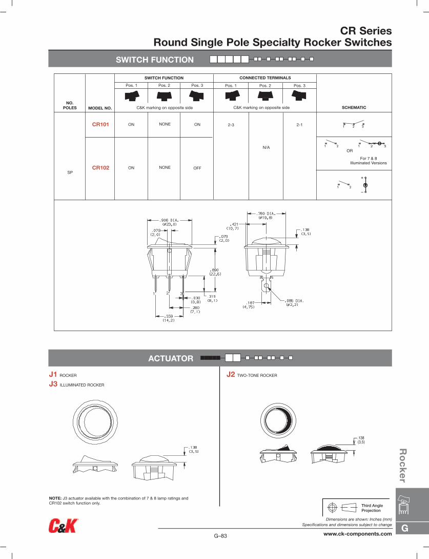
SWITCH FUNCTION
CR SeriesRound Single Pole Specialty Rocker Switches
ACTUATOR
J1 ROCKER
J3 ILLUMINATED ROCKER
NOTE: J3 actuator available with the combination of 7 & 8 lamp ratings andCR102 switch function only.
J2 TWO-TONE ROCKER
.138(3,5)
SWITCH FUNCTION CONNECTED TERMINALS
C&K marking on opposite side C&K marking on opposite sideNO.
POLES MODEL NO. SCHEMATIC
SP
ON ON
ON OFF
CR101
CR102
2-3 2-1
ORFor 7 & 8
Illuminated Versions
NONE
NONE
N/A
For 6 IlluminatedVersions
+
–
OR
For IlluminatedVersion
Pos. 1 Pos. 2 Pos. 3 Pos. 1 Pos. 2 Pos. 3
G
Ro
ck
er
G–83
Dimensions are shown: Inches (mm)Specifications and dimensions subject to change
www.ck-components.com
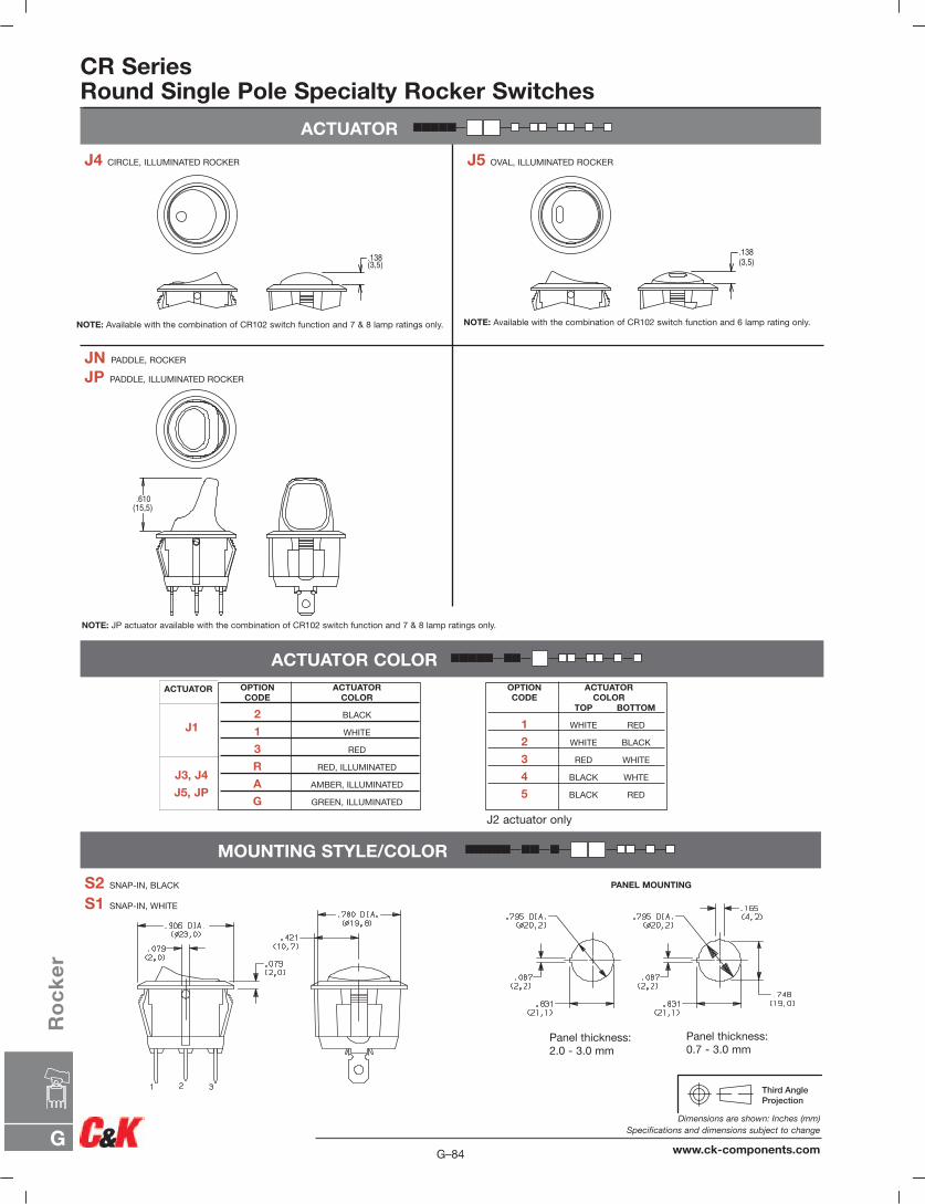
G–84
Dimensions are shown: Inches (mm)Specifications and dimensions subject to change
www.ck-components.comG
Ro
ck
er
ACTUATOR
CR SeriesRound Single Pole Specialty Rocker Switches
ACTUATOR COLOR
MOUNTING STYLE/COLOR
OPTION ACTUATORCODE COLOR
2 BLACK
1 WHITE
3 RED
R RED, ILLUMINATED
A AMBER, ILLUMINATED
G GREEN, ILLUMINATED
J4 CIRCLE, ILLUMINATED ROCKER
JN PADDLE, ROCKER
JP PADDLE, ILLUMINATED ROCKER
NOTE: Available with the combination of CR102 switch function and 7 & 8 lamp ratings only.
J5 OVAL, ILLUMINATED ROCKER
NOTE: Available with the combination of CR102 switch function and 6 lamp rating only.
NOTE: JP actuator available with the combination of CR102 switch function and 7 & 8 lamp ratings only.
S2 SNAP-IN, BLACK
S1 SNAP-IN, WHITE
.138(3,5)
.138(3,5)
.610(15,5)
PANEL MOUNTING
OPTION ACTUATORCODE COLOR
TOP BOTTOM
1 WHITE RED
2 WHITE BLACK
3 RED WHITE
4 BLACK WHTE
5 BLACK RED
J2 actuator only
J1
J3, J4
J5, JP
ACTUATOR
Panel thickness:2.0 - 3.0 mm
Panel thickness:0.7 - 3.0 mm
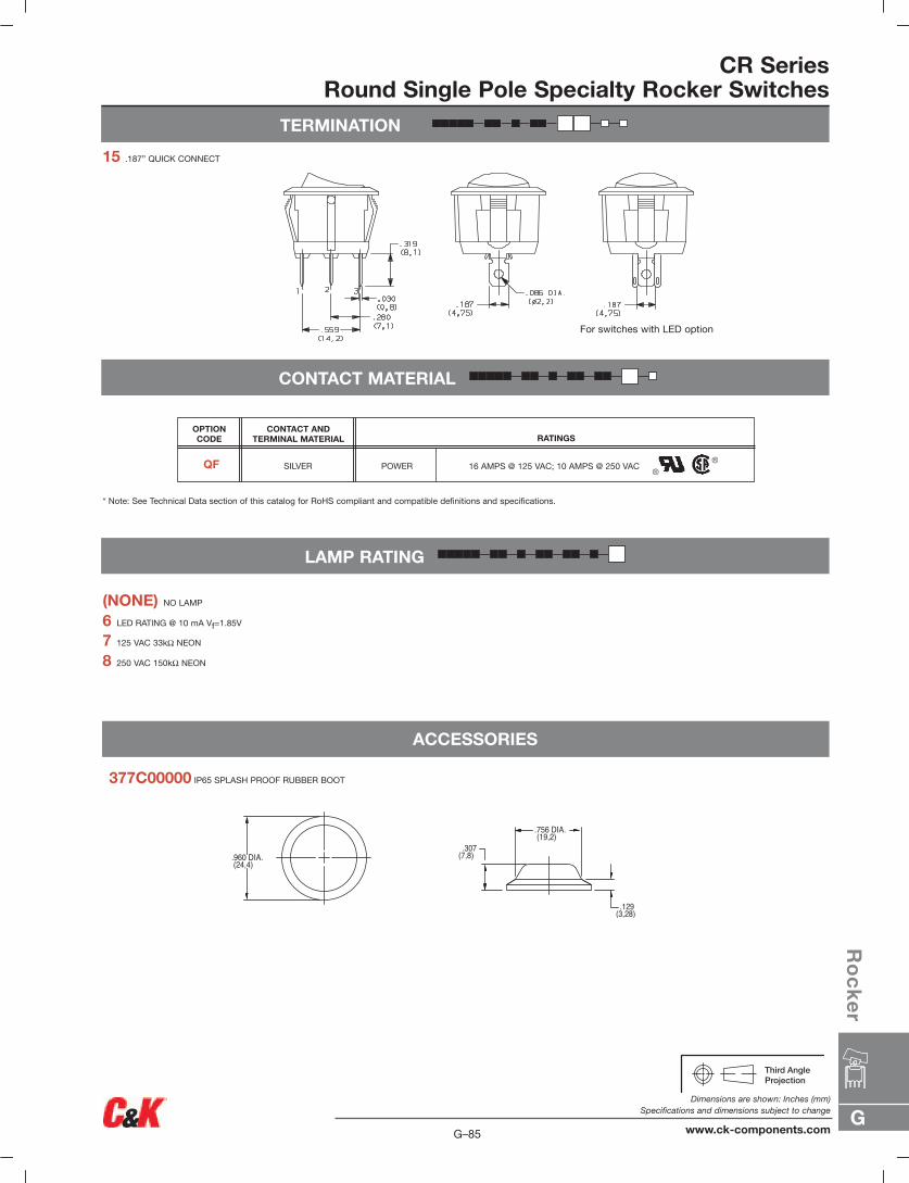
G
Ro
ck
er
G–85
Dimensions are shown: Inches (mm)Specifications and dimensions subject to change
www.ck-components.com
TERMINATION
CR SeriesRound Single Pole Specialty Rocker Switches
CONTACT MATERIAL
LAMP RATING
(NONE) NO LAMP
6 LED RATING @ 10 mA Vf=1.85V
7 125 VAC 33kΩ NEON
8 250 VAC 150kΩ NEON
15 .187” QUICK CONNECT
.307(7,8)
.129(3,28)
.960 DIA.(24,4)
.756 DIA.(19,2)
ACCESSORIES
377C00000 IP65 SPLASH PROOF RUBBER BOOT
* Note: See Technical Data section of this catalog for RoHS compliant and compatible definitions and specifications.
16 AMPS @ 125 VAC; 10 AMPS @ 250 VAC
RATINGSCONTACT AND
TERMINAL MATERIAL
SILVER POWER
OPTION CODE
QF
For switches with LED option
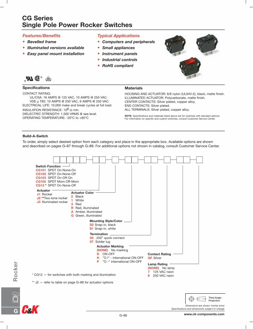
Features/Benefits• Bevelled frame
• Illuminated versions available
• Easy panel mount installation
CG SeriesSingle Pole Power Rocker Switches
Build-A-Switch
To order, simply select desired option from each category and place in the appropriate box. Available options are shown and described on pages G–87 through G–89. For additional options not shown in catalog, consult Customer Service Center.
SpecificationsCONTACT RATING:
UL/CSA: 16 AMPS @ 125 VAC, 10 AMPS @ 250 VAC.VDE µ T85: 10 AMPS @ 250 VAC, 6 AMPS @ 250 VAC.
ELECTRICAL LIFE: 10,000 make and break cycles at full load.
INSULATION RESISTANCE: 108 Ω min.DIELECTRIC STRENGTH: 1,500 VRMS @ sea level.OPERATING TEMPERATURE: -20ºC to +85ºC
MaterialsHOUSING AND ACTUATOR: 6/6 nylon (UL94V-2), black, matte finish.ILLUMINATED ACTUATOR: Polycarbonate, matte finish.CENTER CONTACTS: Silver plated, copper alloy.END CONTACTS: Silver plated.ALL TERMINALS: Silver plated, copper alloy.
NOTE: Specifications and materials listed above are for switches with standard options. For information on specific and custom switches, consult Customer Service Center.
Typical Applications• Computers and peripherals
• Small appliances
• Instrument panels
• Industrial controls
• RoHS compliant
Lamp Rating(NONE) No lamp7 125 VAC neon8 250 VAC neon
Actuator Marking(NONE) No markingD ON-OFFH ”O l” - international ON-OFFP ”O -” international ON-OFF
ActuatorJ1 RockerJ2 **Two-tone rockerJ3 Illuminated rocker
Termination05 .250” quick connect07 Solder lug
Switch FunctionCG101 SPDT On-None-OnCG102 SPST On-None-OffCG103 SPDT On-Off-OnCG105 SPDT Mom-Off-MomCG12 * SPST On-None-Off
Actuator Color2 Black1 White3 RedR Red, illuminatedA Amber, illuminatedG Green, illuminated
Contact RatingQF Silver
Mounting Style/ColorS2 Snap-in, blackS1 Snap-in, white
* CG12 — for switches with both marking and illumination
** J2 — refer to table on page G–88 for actuator options
G–86
Dimensions are shown: Inches (mm)Specifications and dimensions subject to change
www.ck-components.comG
Ro
ck
er

SWITCH FUNCTION
CG SeriesSingle Pole Power Rocker Switches
ACTUATOR
J1 ROCKER
J3 ILLUMINATED ROCKER
J2 TWO-TONE ROCKER
NOTE: J3 actuator available with CG102 switch function only. NOTE: Available with CG102 switch function only.
SWITCH FUNCTION CONNECTED TERMINALS
C&K marking on opposite side
Pos. 1 Pos. 2 Pos. 3 Pos. 1 Pos. 2 Pos. 3
C&K marking on opposite sideNO.
POLES MODEL NO. SCHEMATIC
SP
ON ON
ON OFF
CG101
CG102 1-2
1-2
1-2
1-2
2-3
2-3
2-3
1-2
OR
For IlluminatedVersion
ON ONCG103
NONE
NONE
OFF
N/A
OPEN
OPEN
N/A
OPEN
OPEN
MOM MOMCG105 OFF
ON OFFCG12 * NONE
* CG12 - for switches with both marking and illumination
Shown in Pos. 1
G
Ro
ck
er
G–87
Dimensions are shown: Inches (mm)Specifications and dimensions subject to change
www.ck-components.com
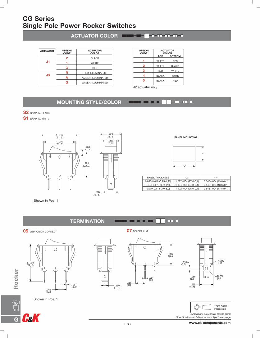
ACTUATOR COLOR
CG SeriesSingle Pole Power Rocker Switches
MOUNTING STYLE/COLOR
S2 SNAP-IN, BLACK
S1 SNAP-IN, WHITE
PANEL MOUNTING
PANEL THICKNESS “X” “Y”
0.030-0.049 (0,75-1,25) 1.087-.004 (27,6-0,1) 0.543+.004 (13,8+0,1)
0.049-0.079 (1,25-2,0) 1.094-.004 (27,8-0,1) 0.543+.004 (13,8+0,1)
0.079-0.118 (2,0-3,0) 1.102-.004 (28,0-0,1) 0.543+.004 (13,8+0,1)
OPTION ACTUATORCODE COLOR
2 BLACK
1 WHITE
3 RED
R RED, ILLUMINATED
A AMBER, ILLUMINATED
G GREEN, ILLUMINATED
TERMINATION
05 .250” QUICK CONNECT
OPTION ACTUATORCODE COLOR
TOP BOTTOM
1 WHITE RED
2 WHITE BLACK
3 RED WHITE
4 BLACK WHTE
5 BLACK RED
J2 actuator only
07 SOLDER LUG
Shown in Pos. 1
Shown in Pos. 1
J1
J3
ACTUATOR
G–88
Dimensions are shown: Inches (mm)Specifications and dimensions subject to change
www.ck-components.comG
Ro
ck
er
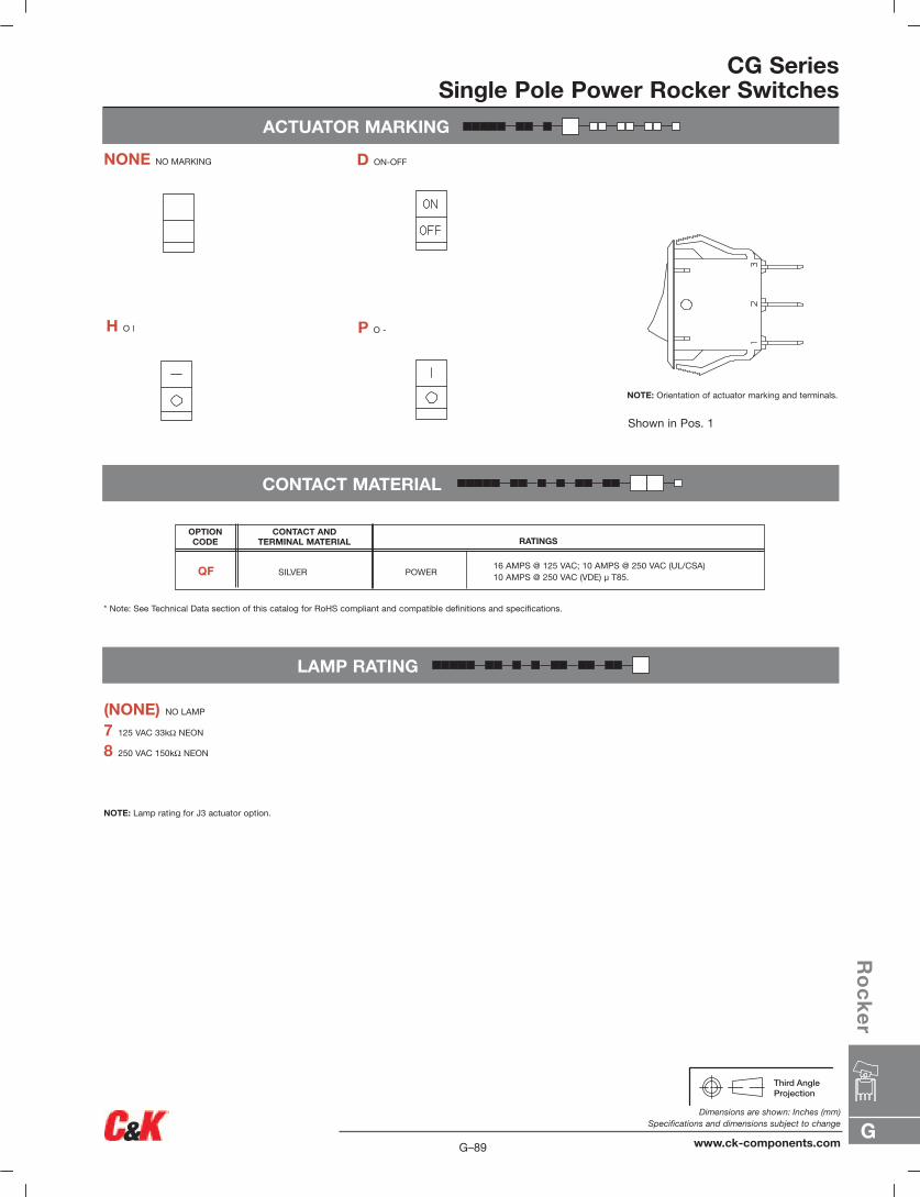
ACTUATOR MARKING
NONE NO MARKING D ON-OFF
H O l P O -
NOTE: Orientation of actuator marking and terminals.
CG SeriesSingle Pole Power Rocker Switches
CONTACT MATERIAL
LAMP RATING
7 125 VAC 33kΩ NEON
8 250 VAC 150kΩ NEON
NOTE: Lamp rating for J3 actuator option.
(NONE) NO LAMP
* Note: See Technical Data section of this catalog for RoHS compliant and compatible definitions and specifications.
16 AMPS @ 125 VAC; 10 AMPS @ 250 VAC (UL/CSA)10 AMPS @ 250 VAC (VDE) µ T85.
RATINGSCONTACT AND
TERMINAL MATERIAL
SILVER POWER
OPTION CODE
QF
Shown in Pos. 1
G
Ro
ck
er
G–89
Dimensions are shown: Inches (mm)Specifications and dimensions subject to change
www.ck-components.com
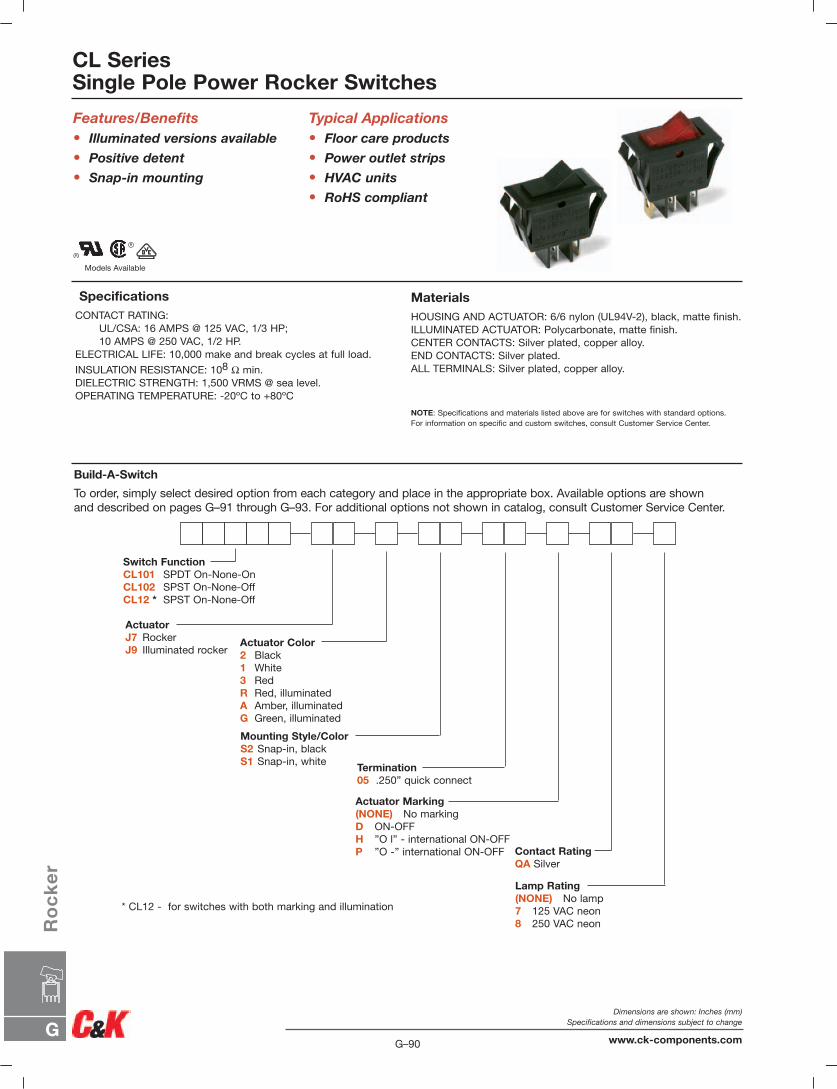
Mounting Style/ColorS2 Snap-in, blackS1 Snap-in, white
CL SeriesSingle Pole Power Rocker Switches
Build-A-Switch
To order, simply select desired option from each category and place in the appropriate box. Available options are shown and described on pages G–91 through G–93. For additional options not shown in catalog, consult Customer Service Center.
SpecificationsCONTACT RATING:
UL/CSA: 16 AMPS @ 125 VAC, 1/3 HP;10 AMPS @ 250 VAC, 1/2 HP.
ELECTRICAL LIFE: 10,000 make and break cycles at full load.
INSULATION RESISTANCE: 108 Ω min.DIELECTRIC STRENGTH: 1,500 VRMS @ sea level.OPERATING TEMPERATURE: -20ºC to +80ºC
Features/Benefits• Illuminated versions available
• Positive detent
• Snap-in mounting
MaterialsHOUSING AND ACTUATOR: 6/6 nylon (UL94V-2), black, matte finish.ILLUMINATED ACTUATOR: Polycarbonate, matte finish.CENTER CONTACTS: Silver plated, copper alloy.END CONTACTS: Silver plated.ALL TERMINALS: Silver plated, copper alloy.
NOTE: Specifications and materials listed above are for switches with standard options. For information on specific and custom switches, consult Customer Service Center.
Typical Applications• Floor care products
• Power outlet strips
• HVAC units
• RoHS compliant
Lamp Rating(NONE) No lamp7 125 VAC neon8 250 VAC neon
Actuator Marking(NONE) No markingD ON-OFFH ”O l” - international ON-OFFP ”O -” international ON-OFF
ActuatorJ7 RockerJ9 Illuminated rocker
Termination05 .250” quick connect
Switch FunctionCL101 SPDT On-None-OnCL102 SPST On-None-OffCL12 * SPST On-None-Off
Actuator Color2 Black1 White3 RedR Red, illuminatedA Amber, illuminatedG Green, illuminated
Contact RatingQA Silver
* CL12 - for switches with both marking and illumination
Models Available
G–90
Dimensions are shown: Inches (mm)Specifications and dimensions subject to change
www.ck-components.comG
Ro
ck
er
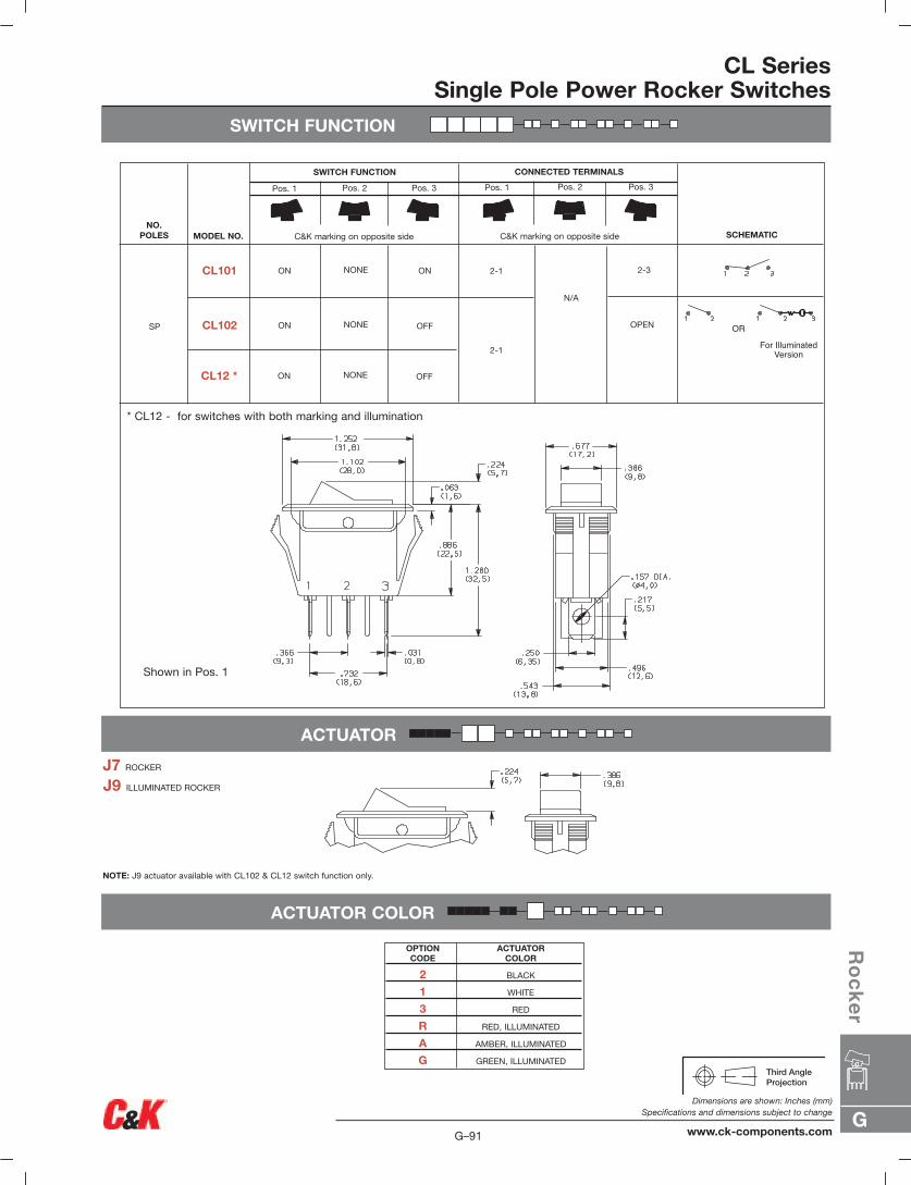
SWITCH FUNCTION
CL SeriesSingle Pole Power Rocker Switches
ACTUATOR
ACTUATOR COLOR
OPTION ACTUATORCODE COLOR
2 BLACK
1 WHITE
3 RED
R RED, ILLUMINATED
A AMBER, ILLUMINATED
G GREEN, ILLUMINATED
J7 ROCKER
J9 ILLUMINATED ROCKER
NOTE: J9 actuator available with CL102 & CL12 switch function only.
SWITCH FUNCTION CONNECTED TERMINALS
C&K marking on opposite side C&K marking on opposite side
Pos. 1 Pos. 2 Pos. 3 Pos. 1 Pos. 2 Pos. 3
NO.POLES MODEL NO. SCHEMATIC
SP
ON ON
ON OFF
CL101
CL102
2-1
2-1 2-3
OPEN OR
For IlluminatedVersion
NONE
NONE
N/A
ON OFFCL12 * NONE
* CL12 - for switches with both marking and illumination
Shown in Pos. 1
G
Ro
ck
er
G–91
Dimensions are shown: Inches (mm)Specifications and dimensions subject to change
www.ck-components.com
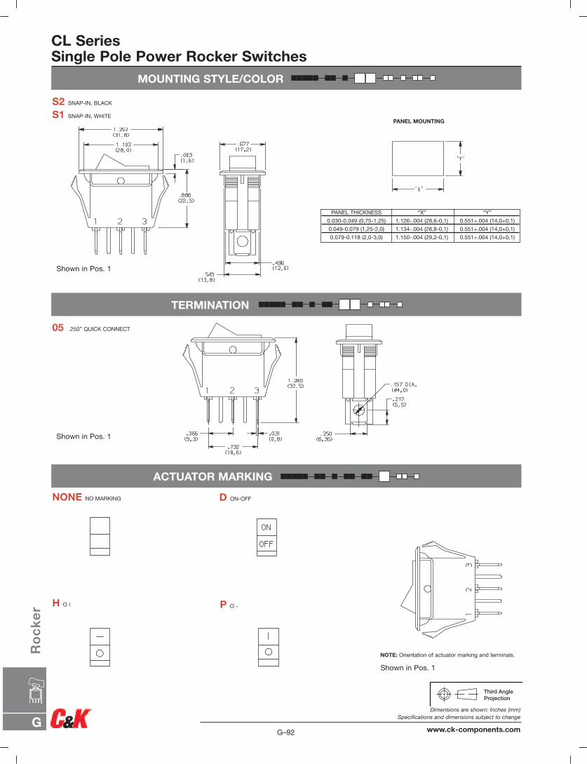
MOUNTING STYLE/COLOR
CL SeriesSingle Pole Power Rocker Switches
TERMINATION
ACTUATOR MARKING
PANEL MOUNTING
PANEL THICKNESS “X” “Y”
0.030-0.049 (0,75-1,25) 1.126-.004 (28,6-0,1) 0.551+.004 (14,0+0,1)
0.049-0.079 (1,25-2,0) 1.134-.004 (28,8-0,1) 0.551+.004 (14,0+0,1)
0.079-0.118 (2,0-3,0) 1.150-.004 (29,2-0,1) 0.551+.004 (14,0+0,1)
S2 SNAP-IN, BLACK
S1 SNAP-IN, WHITE
05 .250” QUICK CONNECT
NONE NO MARKING D ON-OFF
H O l P O -
NOTE: Orientation of actuator marking and terminals.
Shown in Pos. 1
Shown in Pos. 1
Shown in Pos. 1
G–92
Dimensions are shown: Inches (mm)Specifications and dimensions subject to change
www.ck-components.comG
Ro
ck
er
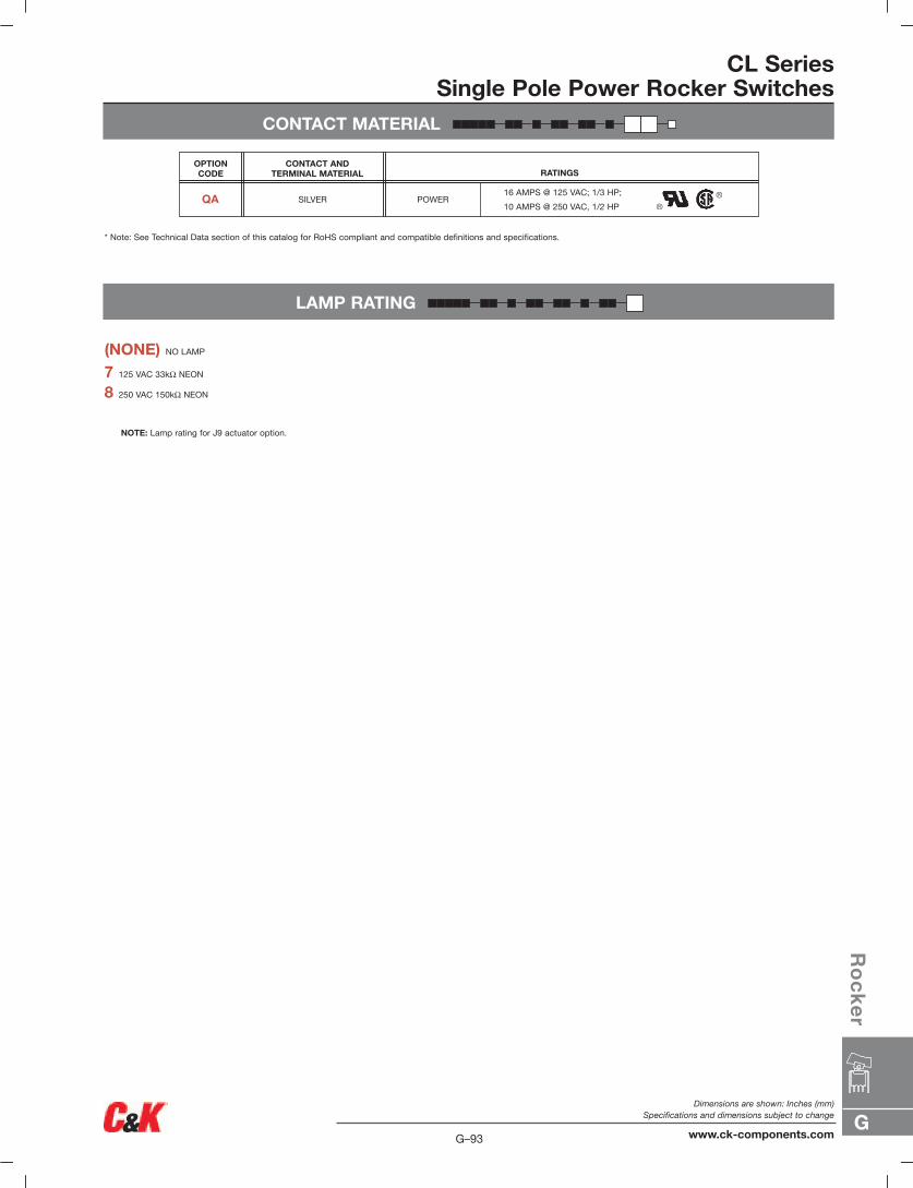
CONTACT MATERIAL
CL SeriesSingle Pole Power Rocker Switches
LAMP RATING
7 125 VAC 33kΩ NEON
8 250 VAC 150kΩ NEON
NOTE: Lamp rating for J9 actuator option.
(NONE) NO LAMP
* Note: See Technical Data section of this catalog for RoHS compliant and compatible definitions and specifications.
16 AMPS @ 125 VAC; 1/3 HP;
10 AMPS @ 250 VAC, 1/2 HP
RATINGSCONTACT AND
TERMINAL MATERIAL
SILVER POWER
OPTION CODE
QA
G
Ro
ck
er
G–93
Dimensions are shown: Inches (mm)Specifications and dimensions subject to change
www.ck-components.com
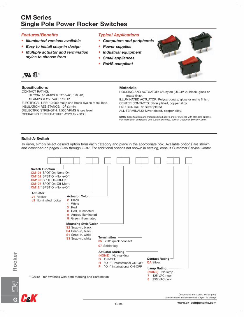
Build-A-SwitchTo order, simply select desired option from each category and place in the appropriate box. Available options are shownand described on pages G–95 through G–97. For additional options not shown in catalog, consult Customer Service Center.
SpecificationsCONTACT RATING:
UL/CSA: 16 AMPS @ 125 VAC, 1/8 HP;10 AMPS @ 250 VAC, 1/3 HP.
ELECTRICAL LIFE: 10,000 make and break cycles at full load.INSULATION RESISTANCE: 108 Ω min.DIELECTRIC STRENGTH: 1,500 VRMS @ sea level.OPERATING TEMPERATURE: -20ºC to +80ºC
Features/Benefits• Illuminated versions available
• Easy to install snap-in design
• Multiple actuator and terminationstyles to choose from
MaterialsHOUSING AND ACTUATOR: 6/6 nylon (UL94V-2), black, gloss or
matte finish.ILLUMINATED ACTUATOR: Polycarbonate, gloss or matte finish.CENTER CONTACTS: Silver plated, copper alloy.END CONTACTS: Silver plated.ALL TERMINALS: Silver plated, copper alloy.
NOTE: Specifications and materials listed above are for switches with standard options. For information on specific and custom switches, consult Customer Service Center.
Typical Applications• Computers and peripherals
• Power supplies
• Industrial equipment
• Small appliances
• RoHS compliant
Lamp Rating(NONE) No lamp7 125 VAC neon8 250 VAC neon
Actuator Marking(NONE) No markingD ON-OFFH ”O l” - international ON-OFFP ”O -” international ON-OFF
ActuatorJ1 RockerJ3 Illuminated rocker
Switch FunctionCM101 SPDT On-None-OnCM102 SPST On-None-OffCM103 SPDT On-Off-OnCM107 SPDT On-Off-Mom.CM12 * SPST On-None-Off
Actuator Color2 Black1 White3 RedR Red, illuminatedA Amber, illuminatedG Green, illuminated
Contact RatingQA Silver
Mounting Style/ColorS2 Snap-in, blackS4 Snap-in, blackS1 Snap-in, whiteS3 Snap-in, white Termination
05 .250” quick connect
07 Solder lug
* CM12 - for switches with both marking and illumination
CM SeriesSingle Pole Power Rocker Switches
G–94
Dimensions are shown: Inches (mm)Specifications and dimensions subject to change
www.ck-components.comG
Ro
ck
er
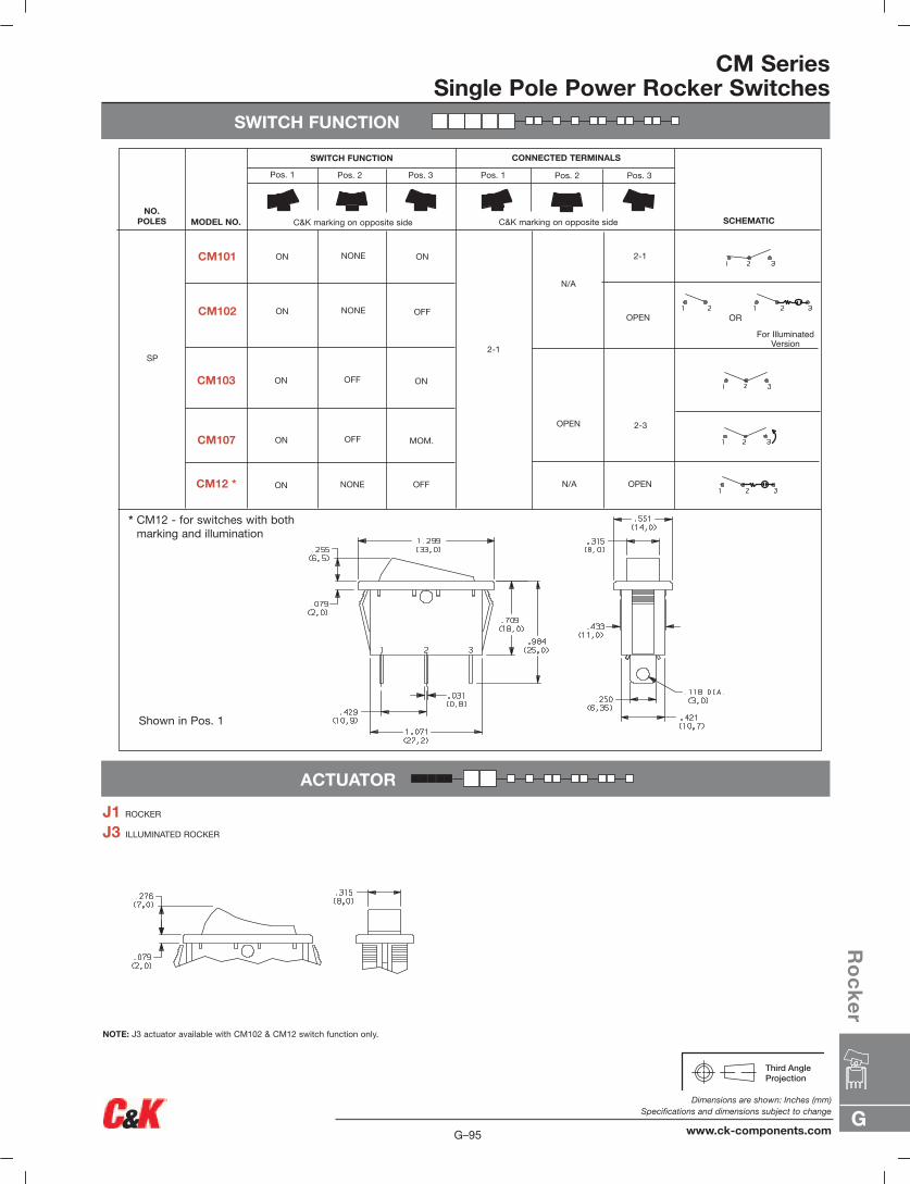
SWITCH FUNCTION
CM SeriesSingle Pole Power Rocker Switches
ACTUATOR
J1 ROCKER
J3 ILLUMINATED ROCKER
NOTE: J3 actuator available with CM102 & CM12 switch function only.
SWITCH FUNCTION CONNECTED TERMINALS
C&K marking on opposite side
Pos. 1 Pos. 2 Pos. 3 Pos. 1 Pos. 2 Pos. 3
C&K marking on opposite sideNO.
POLES MODEL NO. SCHEMATIC
SP
ON ON
ON OFF
CM101
CM102
2-1
2-1
2-3
N/A OPEN
OPEN OR
For IlluminatedVersion
ON ONCM103
NONE
NONE
OFF
N/A
OPEN
ON MOM.CM107 OFF
ON OFFCM12 * NONE
* CM12 - for switches with bothmarking and illumination
Shown in Pos. 1
G
Ro
ck
er
G–95
Dimensions are shown: Inches (mm)Specifications and dimensions subject to change
www.ck-components.com
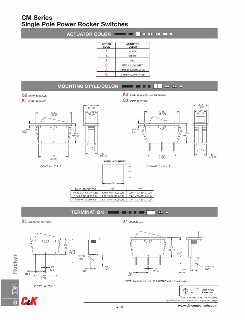
ACTUATOR COLOR
CM SeriesSingle Pole Power Rocker Switches
MOUNTING STYLE/COLOR
OPTION ACTUATORCODE COLOR
2 BLACK
1 WHITE
3 RED
R RED, ILLUMINATED
A AMBER, ILLUMINATED
G GREEN, ILLUMINATED
PANEL MOUNTING
PANEL THICKNESS “X” “Y”
0.030-0.049 (0,75-1,25) 1.189-.004 (30,2-0,1) 0.441+.004 (11,2+0,1)
0.049-0.079 (1,25-2,0) 1.197-.004 (30,4-0,1) 0.441+.004 (11,2+0,1)
0.079-0.118 (2,0-3,0) 1.212-.004 (30,8-0,1) 0.441+.004 (11,2+0,1)
S2 SNAP-IN, BLACK
S1 SNAP-IN, WHITE
S4 SNAP-IN, BLACK (SHORT FRAME)
S3 SNAP-IN, WHITE
TERMINATION
05 .250 QUICK CONNECT 07 SOLDER LUG
NOTE: Available with CM101 & CM102 switch functions only.
.709(18,0)
1.124(28,55)
.031(0,8)
.429(10,9) 1.071
(27,2)
.250(6,35)
.185(4,7)
.063 DIA.(1,60)
31 2
Shown in Pos. 1
Shown in Pos. 1
Shown in Pos. 1
G–96
Dimensions are shown: Inches (mm)Specifications and dimensions subject to change
www.ck-components.comG
Ro
ck
er

ACTUATOR MARKING
NONE NO MARKING D ON-OFF
H O l P O -
NOTE: Orientation of actuator marking and terminals.
CM SeriesSingle Pole Power Rocker Switches
CONTACT MATERIAL
LAMP RATING
7 125 VAC 33kΩ NEON
8 250 VAC 150kΩ NEON
NOTE: Lamp rating for J3 & J8 actuator option.
(NONE) NO LAMP
* Note: See Technical Data section of this catalog for RoHS compliant and compatible definitions and specifications.
16 AMPS @ 125 VAC; 1/8 HP
10 AMPS @ 250 VAC, 1/3 HP (UL/CSA).
RATINGSCONTACT AND
TERMINAL MATERIAL
SILVER POWER
OPTION CODE
QA
Shown in Pos. 1
G
Ro
ck
er
G–97
Dimensions are shown: Inches (mm)Specifications and dimensions subject to change
www.ck-components.com
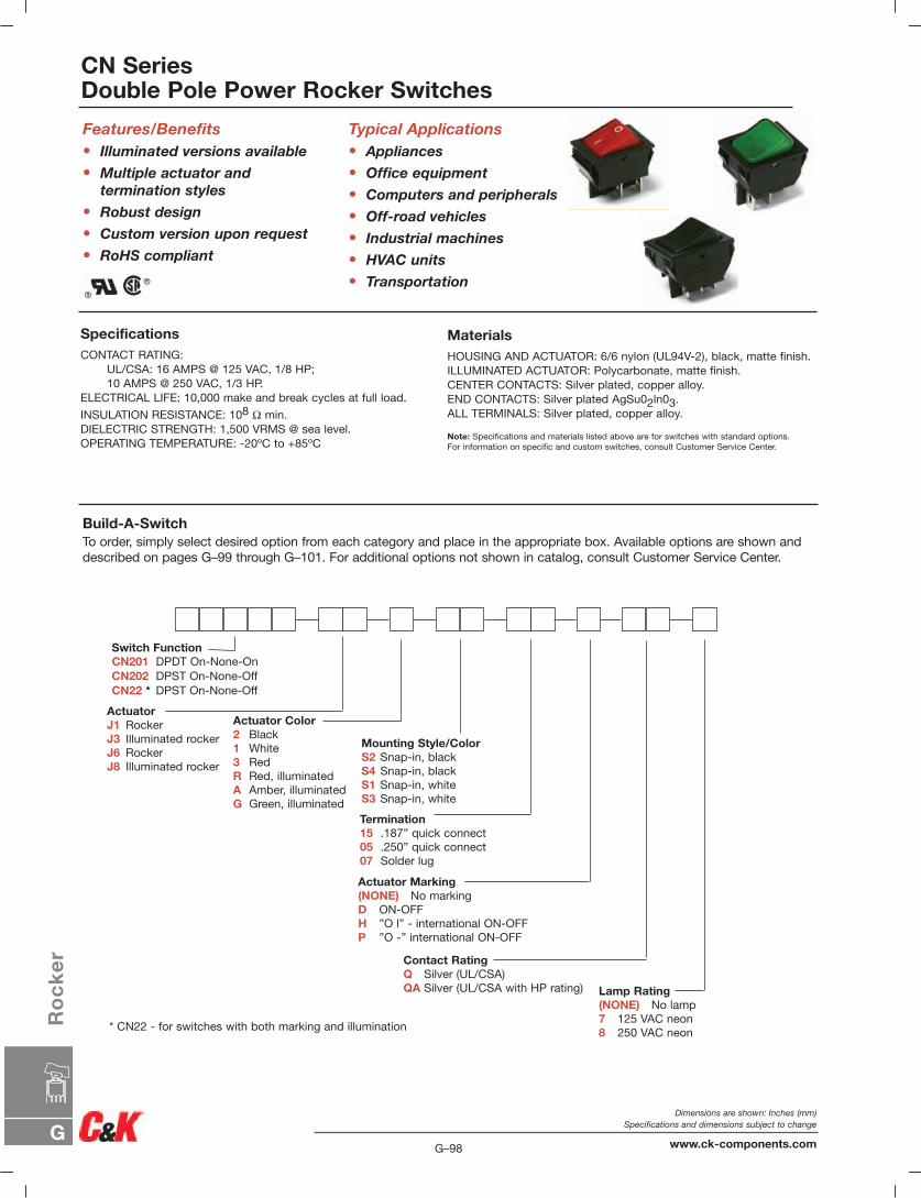
Switch FunctionCN201 DPDT On-None-OnCN202 DPST On-None-OffCN22 * DPST On-None-Off
CN SeriesDouble Pole Power Rocker Switches
Build-A-SwitchTo order, simply select desired option from each category and place in the appropriate box. Available options are shown anddescribed on pages G–99 through G–101. For additional options not shown in catalog, consult Customer Service Center.
SpecificationsCONTACT RATING:
UL/CSA: 16 AMPS @ 125 VAC, 1/8 HP;10 AMPS @ 250 VAC, 1/3 HP.
ELECTRICAL LIFE: 10,000 make and break cycles at full load.
INSULATION RESISTANCE: 108 Ω min.DIELECTRIC STRENGTH: 1,500 VRMS @ sea level.OPERATING TEMPERATURE: -20ºC to +85ºC
Features/Benefits• Illuminated versions available
• Multiple actuator and termination styles
• Robust design
• Custom version upon request
• RoHS compliant
MaterialsHOUSING AND ACTUATOR: 6/6 nylon (UL94V-2), black, matte finish.ILLUMINATED ACTUATOR: Polycarbonate, matte finish.CENTER CONTACTS: Silver plated, copper alloy.END CONTACTS: Silver plated AgSu02ln03.ALL TERMINALS: Silver plated, copper alloy.
Note: Specifications and materials listed above are for switches with standard options. For information on specific and custom switches, consult Customer Service Center.
Typical Applications• Appliances
• Office equipment
• Computers and peripherals
• Off-road vehicles
• Industrial machines
• HVAC units
• Transportation
Lamp Rating(NONE) No lamp7 125 VAC neon8 250 VAC neon
Actuator Marking(NONE) No markingD ON-OFFH ”O l” - international ON-OFFP ”O -” international ON-OFF
ActuatorJ1 RockerJ3 Illuminated rockerJ6 RockerJ8 Illuminated rocker
Termination15 .187” quick connect05 .250” quick connect07 Solder lug
Actuator Color2 Black1 White3 RedR Red, illuminatedA Amber, illuminatedG Green, illuminated
Contact RatingQ Silver (UL/CSA)QA Silver (UL/CSA with HP rating)
Mounting Style/ColorS2 Snap-in, blackS4 Snap-in, blackS1 Snap-in, whiteS3 Snap-in, white
* CN22 - for switches with both marking and illumination
G–98
Dimensions are shown: Inches (mm)Specifications and dimensions subject to change
www.ck-components.comG
Ro
ck
er
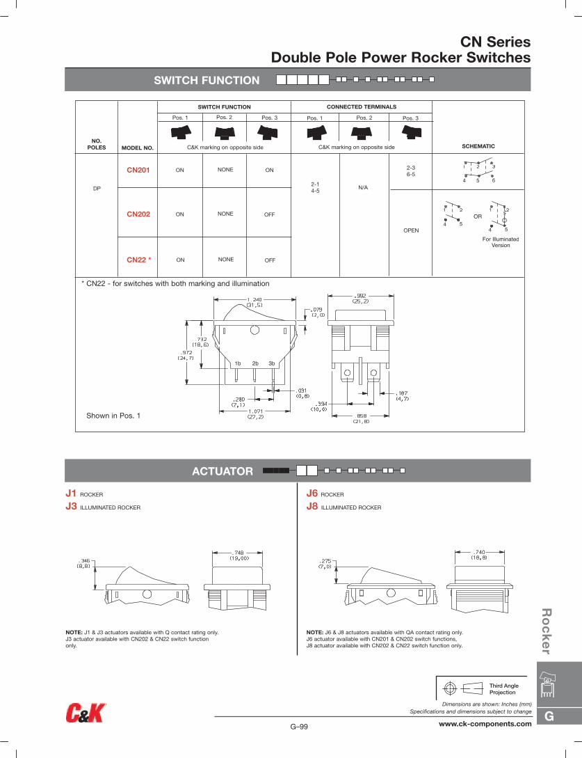
SWITCH FUNCTION
CN SeriesDouble Pole Power Rocker Switches
ACTUATOR
J1 ROCKER
J3 ILLUMINATED ROCKER
NOTE: J1 & J3 actuators available with Q contact rating only.J3 actuator available with CN202 & CN22 switch functiononly.
J6 ROCKER
J8 ILLUMINATED ROCKER
NOTE: J6 & J8 actuators available with QA contact rating only.J6 actuator available with CN201 & CN202 switch functions,J8 actuator available with CN202 & CN22 switch function only.
1b 3b2b
SWITCH FUNCTION CONNECTED TERMINALS
C&K marking on opposite side
Pos. 1
C&K marking on opposite sideNO.
POLES MODEL NO. SCHEMATIC
DP
ON ON
ON OFF
CN201
CN202
2-14-5
2-36-5
OR
For IlluminatedVersion
NONE
NONE
N/A
OPEN
ON OFFCN22 * NONE
* CN22 - for switches with both marking and illumination
Shown in Pos. 1
Pos. 2 Pos. 3 Pos. 1 Pos. 2 Pos. 3
G
Ro
ck
er
G–99
Dimensions are shown: Inches (mm)Specifications and dimensions subject to change
www.ck-components.com
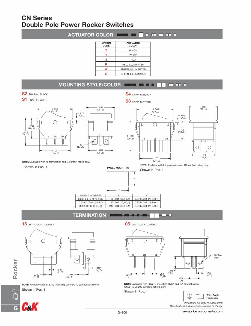
ACTUATOR COLOR
MOUNTING STYLE/COLOR
CN SeriesDouble Pole Power Rocker Switches
OPTION ACTUATORCODE COLOR
2 BLACK
1 WHITE
3 RED
R RED, ILLUMINATED
A AMBER, ILLUMINATED
G GREEN, ILLUMINATED
PANEL MOUNTING
PANEL THICKNESS “X” “Y”
0.030-0.049 (0,75-1,25) 1.190-.004 (30,2-0,1) 0.874+.004 (22,2+0,1)
0.049-0.079 (1,25-2,0) 1.197-.004 (30,4-0,1) 0.874+.004 (22,2+0,1)
0.079-0.118 (2,0-3,0) 1.213-.004 (30,8-0,1) 0.874+.004 (22,2+0,1)
S4 SNAP-IN, BLACK
S3 SNAP-IN, WHITE
S2 SNAP-IN, BLACK
S1 SNAP-IN, WHITE
1b 3b2b1b 3b2b
TERMINATION
15 .187” QUICK CONNECT 05 .250” QUICK CONNECT
NOTE: Available with S1 & S2 mounting style and Q contact rating only.
TERMINA
1b 3b2b
.425(1,8)
.102 DIA.(ø2,6)
.250(6,35)
.413(10,5)
NOTE: Available with 15 termination and Q contact rating only.NOTE: Available with 05 termination and QA contact rating only.
NOTE: Available with S3 & S4 mounting styles and QA contact rating,CN201 & CN202 switch functions only.
Shown in Pos. 1Shown in Pos. 1
Shown in Pos. 1Shown in Pos. 1
G–100
Dimensions are shown: Inches (mm)Specifications and dimensions subject to change
www.ck-components.comG
Ro
ck
er
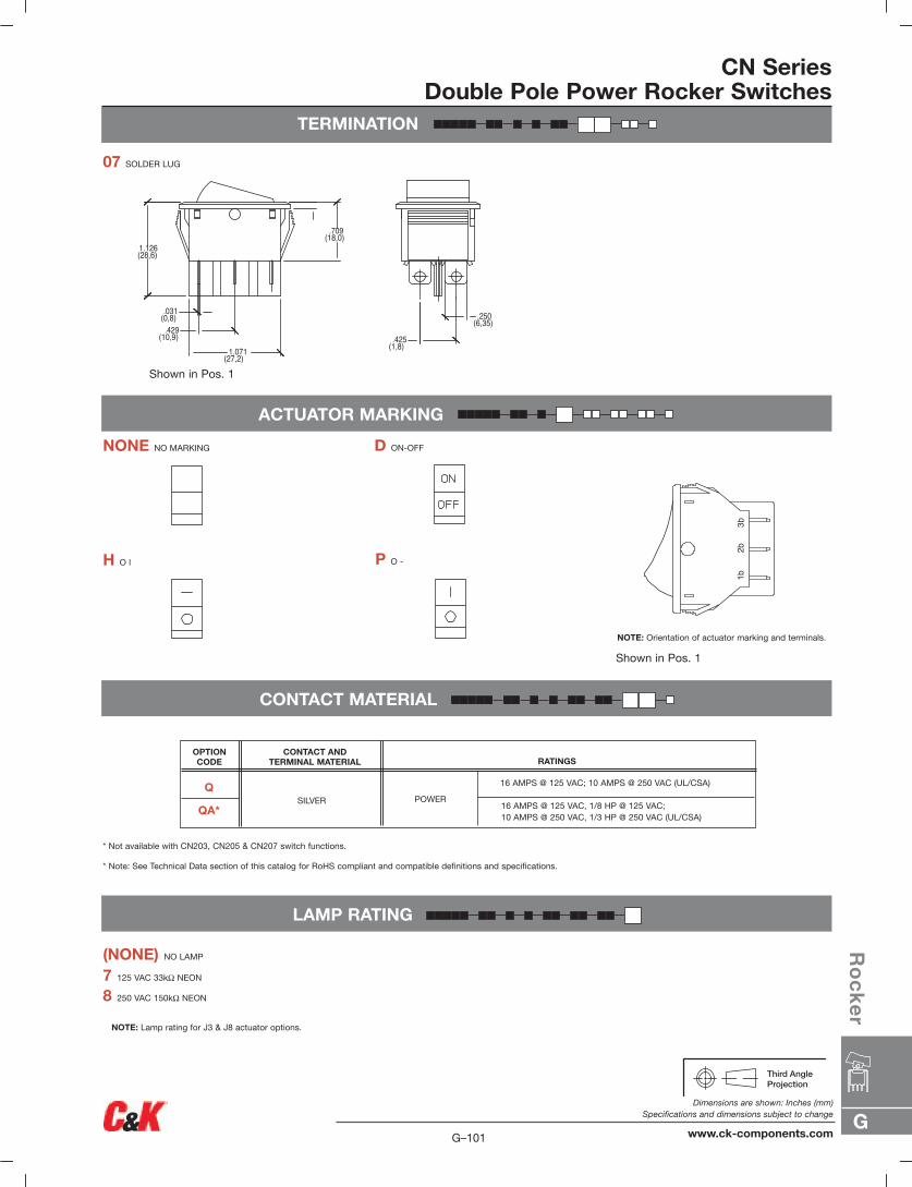
CONTACT MATERIAL
LAMP RATING
7 125 VAC 33kΩ NEON
8 250 VAC 150kΩ NEON
NOTE: Lamp rating for J3 & J8 actuator options.
* Not available with CN203, CN205 & CN207 switch functions.
(NONE) NO LAMP
ACTUATOR MARKING
NONE NO MARKING D ON-OFF
H O l P O -
NOTE: Orientation of actuator marking and terminals.
1b3b
2b
CN SeriesDouble Pole Power Rocker Switches
07 SOLDER LUG
.031(0,8).429
(10,9)1.071
(27,2)
.709(18,0)
1.126(28,6)
.425(1,8)
.250(6,35)
TERMINATION
* Note: See Technical Data section of this catalog for RoHS compliant and compatible definitions and specifications.
16 AMPS @ 125 VAC, 1/8 HP @ 125 VAC;10 AMPS @ 250 VAC, 1/3 HP @ 250 VAC (UL/CSA)
RATINGSCONTACT AND
TERMINAL MATERIAL
SILVER POWER
OPTION CODE
Q
QA*
16 AMPS @ 125 VAC; 10 AMPS @ 250 VAC (UL/CSA)
Shown in Pos. 1
Shown in Pos. 1
G
Ro
ck
er
G–101
Dimensions are shown: Inches (mm)Specifications and dimensions subject to change
www.ck-components.com

Models Available
C SeriesPower Rocker Switches
Features/Benefits• Positive detent
• Attractive design
• Snap-in mounting
Typical Applications• Floor care products
• Power outlet strips
• Small appliances
• RoHS compliant
Specifications
CONTACT RATING: All Models: 15 AMPS @ 125 V AC; 10 AMPS
@ 250 V AC . Models also available with
see rating section.
ELECTRICAL LIFE: 10,000 make-and-break cycles at full load.
INSULATION RESISTANCE: 109 Ω min.
DIELECTRIC STRENGTH: 2,500 Vrms min. @ sea level.
NOTE: Specifications and materials listed above are for switches with standard options.For information on specific and custom switches, consult Customer Service center.
MaterialsHOUSING & ACTUATOR: 6/6 nylon (UL 94V-2), black (standard).
MOVABLE CONTACTS: Copper, silver plated.
STATIONARY CONTACT & TERMINALS:C121, C122 models with ‘QA’ rating: Copper, silver plated.C221, C222 models with ‘QA’ rating: Copper.All models with ‘QF’ rating: Copper, silver plated.
CONTACT SPRING: Music wire or stainless steel.
OPERATING TEMPERATURE: -30ºC to +65ºC
Build-A-SwitchTo order, simply select desired option from each category and place in the appropriate box. Available options are shown anddescribed on pages G-103 and G-104. For additional options not shown in catalog, consult Customer Service Center.
Switch FunctionC121 SPDT, On-OnC122 SPST, On-OffC221 DPDT, On-OnC222 DPST, On-Off
ActuatorJ1 Rocker
Actuator Color2 Black1 White3 Red
Mounting Style/ColorS2 Snap-in, blackS1 Snap-in, white
Contact MaterialQA Silver (UL/CSA)QF Silver (UL/CSA/VDE)
Terminations05 Quick connectWC Wire Wrap
Actuator MarkingsNONE No markingsD ON-OFFP O –
G–102
Dimensions are shown: Inches (mm)Specifications and dimensions subject to change
www.ck-components.comG
Ro
ck
er
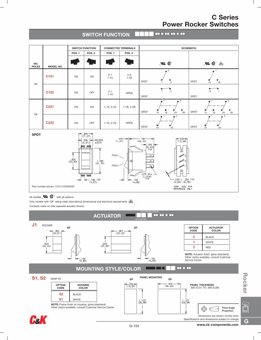
C SeriesPower Rocker Switches
SWITCH FUNCTION
SP DP
PANEL MOUNTINGSP DP
PANEL THICKNESS:.020 (0,51) TO .200 (5,08)
DPDT
DPST
DPDT
DPST
1-1B, 2-2B
OPEN
1-1A, 2-2A
1-1A, 2-2A
ON
OFF
ON
ON
C221
C222
DP
SPDT
SPST
SPDT
SPST
2-31-1B
OPEN
2-11-1A
2-11-1A
ON
OFF
ON
ON
C121
C122
SP
SCHEMATICCONNECTED TERMINALS
POS. 1 POS. 2
SWITCH FUNCTION
POS. 1 POS. 2
MODEL NO.NO.
POLES
1 3
2
1A 1B
1
1 2 1A 1
1A
1
2A
2
1A
1
2A
21A
1
1B 2A 2B
2
1A
1
1B 2A 2B
2
SPDT
Part number shown: C121J12S205QF
All models with all options.
Only models with ‘QF’ rating meet international dimensional and electrical requirements .Contacts make on side opposite actuator thrown.
NOTE: Actuator finish: gloss (standard). Other colors available, consult CustomerService Center.
2 BLACK
1 WHITE
3 RED
ACTUATORCOLOR
OPTION CODE
J1 ROCKER
S1, S2 SNAP-IN
ACTUATOR
MOUNTING STYLE/COLOR
ACTUATOR COLOR
ACTUATOR
NOTE: Frame finish on housing: gloss (standard).Other colors available, consult Customer Service Center.
S2 BLACK
S1 WHITE
HOUSINGCOLOR
OPTION CODE
G
Ro
ck
er
G–103
Dimensions are shown: Inches (mm)Specifications and dimensions subject to change
www.ck-components.com
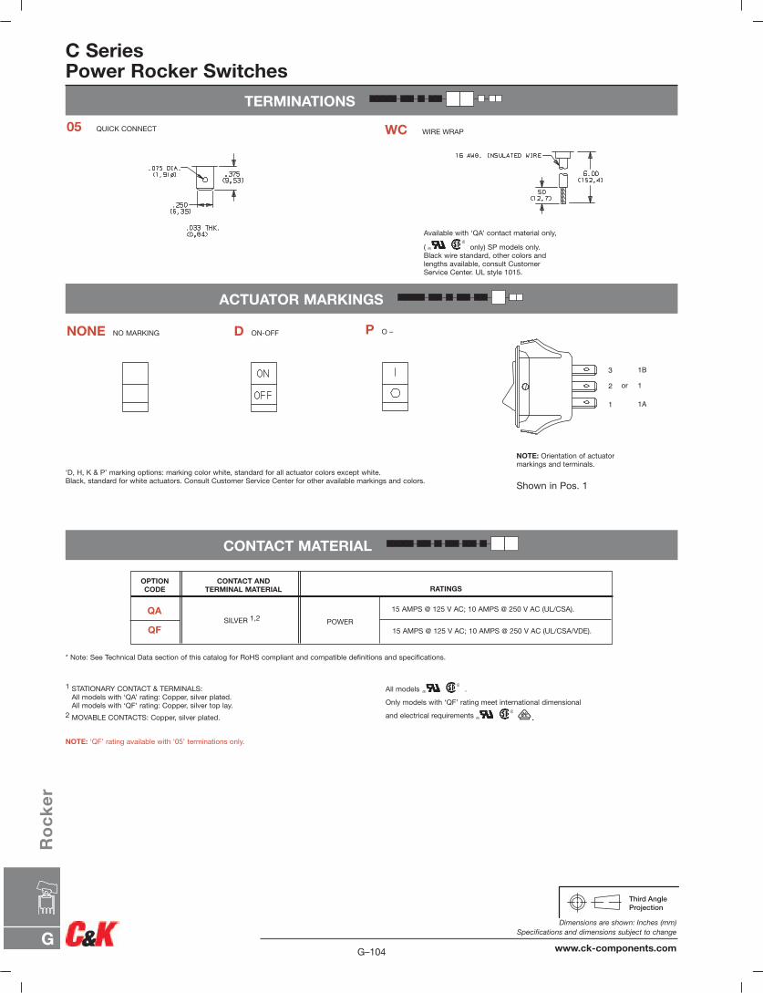
C SeriesPower Rocker Switches
TERMINATIONS
ACTUATOR MARKINGS
CONTACT MATERIAL
2
1
3
or
1B
1
1A
05 QUICK CONNECT WC WIRE WRAP
NONE NO MARKING D ON-OFF P O –
‘D, H, K & P’ marking options: marking color white, standard for all actuator colors except white.Black, standard for white actuators. Consult Customer Service Center for other available markings and colors.
NOTE: Orientation of actuatormarkings and terminals.
Available with ‘QA’ contact material only,
( only) SP models only.Black wire standard, other colors andlengths available, consult CustomerService Center. UL style 1015.
1 STATIONARY CONTACT & TERMINALS:All models with ‘QA’ rating: Copper, silver plated.All models with ‘QF’ rating: Copper, silver top lay.
2 MOVABLE CONTACTS: Copper, silver plated.
NOTE: ‘QF’ rating available with ‘05’ terminations only.
All models .
Only models with ‘QF’ rating meet international dimensional
and electrical requirements .
* Note: See Technical Data section of this catalog for RoHS compliant and compatible definitions and specifications.
15 AMPS @ 125 V AC; 10 AMPS @ 250 V AC (UL/CSA/VDE).
RATINGSCONTACT AND
TERMINAL MATERIAL
SILVER 1,2 POWER
OPTION CODE
QA
QF
15 AMPS @ 125 V AC; 10 AMPS @ 250 V AC (UL/CSA).
Shown in Pos. 1
G–104
Dimensions are shown: Inches (mm)Specifications and dimensions subject to change
www.ck-components.comG
Ro
ck
er
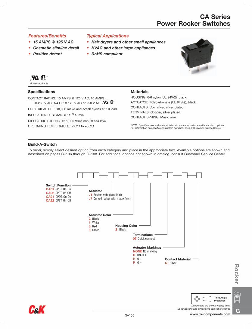
Models Available
CA SeriesPower Rocker Switches
Features/Benefits• 15 AMPS @ 125 V AC
• Cosmetic slimline detail
• Positive detent
Typical Applications• Hair dryers and other small appliances
• HVAC and other large appliances
• RoHS compliant
Specifications
CONTACT RATING: 15 AMPS @ 125 V AC; 10 AMPS
@ 250 V AC; 1/4 HP @ 125 V AC or 250 V AC .
ELECTRICAL LIFE: 10,000 make-and-break cycles at full load.
INSULATION RESISTANCE: 109 Ω min.
DIELECTRIC STRENGTH: 1,000 Vrms min. @ sea level.
OPERATING TEMPERATURE: -30ºC to +85ºC
MaterialsHOUSING: 6/6 nylon (UL 94V-2), black.
ACTUATOR: Polycarbonate (UL 94V-2), black.
CONTACTS: Coin silver, silver plated.
TERMINALS: Copper, silver plated.
CONTACT SPRING: Music wire.
NOTE: Specifications and material listed above are for switches with standard options.For information on specific and custom switches, consult Customer Service Center.
Build-A-SwitchTo order, simply select desired option from each category and place in the appropriate box. Available options are shown anddescribed on pages G–106 through G–108. For additional options not shown in catalog, consult Customer Service Center.
Switch FunctionCA01 SPDT, On-OnCA02 SPST, On-OffCA21 DPDT, On-OnCA22 DPST, On-Off
ActuatorJ1 Rocker with gloss finishJ7 Curved rocker with matte finish
Actuator Color2 Black1 White3 Red6 Green
Housing Color2 Black
Contact MaterialQ Silver
Terminations07 Quick connect
Actuator MarkingsNONE No markingD ON-OFFH O |P O –
G
Ro
ck
er
G–105
Dimensions are shown: Inches (mm)Specifications and dimensions subject to change
www.ck-components.com

CA SeriesPower Rocker Switches
SWITCH FUNCTION
DPDT
DPST
1-1B, 2-2B
OPEN
1-1A, 2-2A
1-1A, 2-2A
ON
OFF
ON
ON
CA21
CA22
DP
SPDT
SPST
1-1B
OPEN
1-1A
1-1A
ON
OFF
ON
ON
CA01
CA02
SP
SCHEMATIC
CONNECTED TERMINALS
POS. 1 POS. 2
SWITCH FUNCTION
POS. 1 POS. 2
MODEL NO.
NO.POLES
DPDT
SPDT
Part number shown: CA01J12207Q
Part number shown: CA21J12207Q
For complete contact ratings and agency approvals, see CONTACT MATERIAL section, page G–108.Contacts make on side opposite actuator thrown.
All models with all options.
1A 1
G–106
Dimensions are shown: Inches (mm)Specifications and dimensions subject to change
www.ck-components.comG
Ro
ck
er
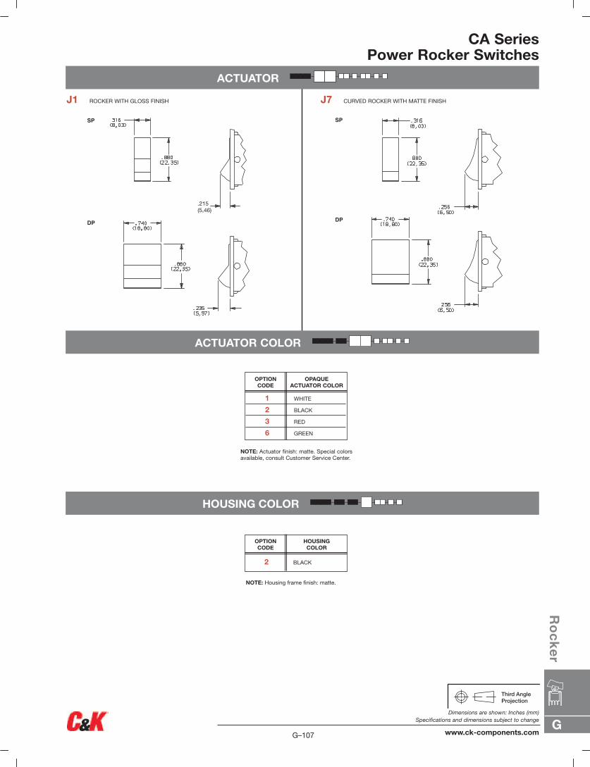
ACTUATOR COLOR
HOUSING COLOR
CA SeriesPower Rocker Switches
ACTUATOR
SP
DP
.215(5,46)
SP
DP
J1 ROCKER WITH GLOSS FINISH J7 CURVED ROCKER WITH MATTE FINISH
2 BLACK
HOUSINGCOLOR
OPTION CODE
OPAQUEACTUATOR COLOR
OPTION CODE
NOTE: Housing frame finish: matte.
NOTE: Actuator finish: matte. Special colorsavailable, consult Customer Service Center.
1 WHITE
2 BLACK
3 RED
6 GREEN
G
Ro
ck
er
G–107
Dimensions are shown: Inches (mm)Specifications and dimensions subject to change
www.ck-components.com
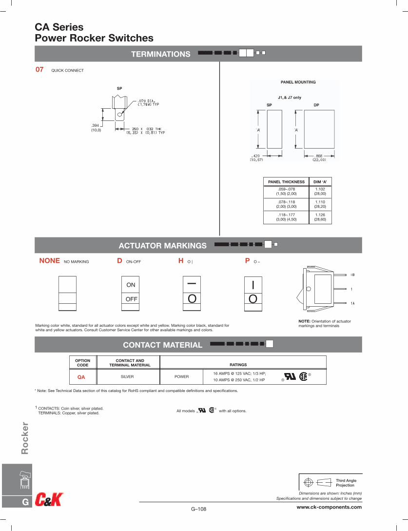
CA SeriesPower Rocker Switches
CONTACT MATERIAL
ON
OFF O
I
OI
SP
.394(10,0)
ACTUATOR MARKINGS
07 QUICK CONNECT
TERMINATIONS
NONE NO MARKING D ON-OFF H O | P O –
NOTE: Orientation of actuator markings and terminalsMarking color white, standard for all actuator colors except white and yellow. Marking color black, standard for
white and yellow actuators. Consult Customer Service Center for other available markings and colors.
1.126(28,60)
.118–.177(3,00) (4,50)
1.110(28,20)
.078–.118(2,00) (3,00)
1.102(28,00)
.059–.078(1,50) (2,00)
DIM ‘A’PANEL THICKNESS
1 CONTACTS: Coin silver, silver plated.TERMINALS: Copper, silver plated. All models with all options.
* Note: See Technical Data section of this catalog for RoHS compliant and compatible definitions and specifications.
16 AMPS @ 125 VAC; 1/3 HP;
10 AMPS @ 250 VAC, 1/2 HP
RATINGSCONTACT AND
TERMINAL MATERIAL
SILVER POWER
OPTION CODE
QA
G–108
Dimensions are shown: Inches (mm)Specifications and dimensions subject to change
www.ck-components.comG
Ro
ck
er
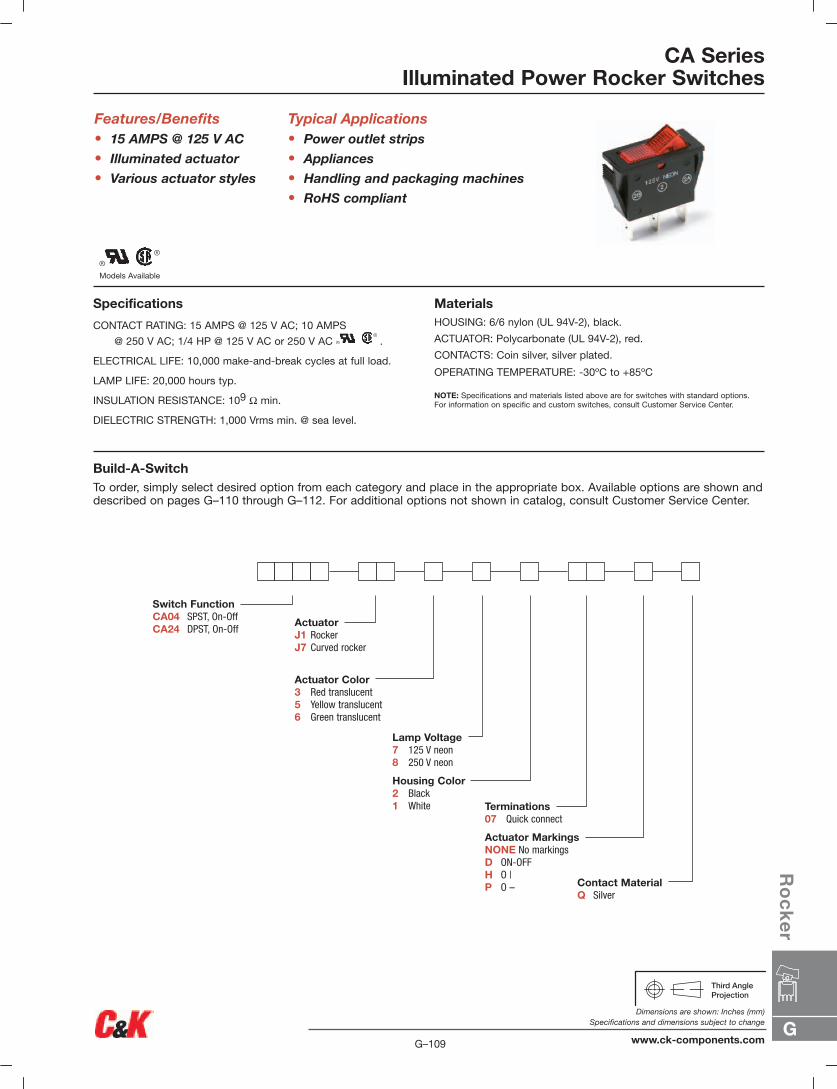
Models Available
Specifications
CONTACT RATING: 15 AMPS @ 125 V AC; 10 AMPS
@ 250 V AC; 1/4 HP @ 125 V AC or 250 V AC .
ELECTRICAL LIFE: 10,000 make-and-break cycles at full load.
LAMP LIFE: 20,000 hours typ.
INSULATION RESISTANCE: 109 Ω min.
DIELECTRIC STRENGTH: 1,000 Vrms min. @ sea level.
CA SeriesIlluminated Power Rocker Switches
Features/Benefits• 15 AMPS @ 125 V AC
• Illuminated actuator
• Various actuator styles
Typical Applications• Power outlet strips
• Appliances
• Handling and packaging machines
• RoHS compliant
MaterialsHOUSING: 6/6 nylon (UL 94V-2), black.
ACTUATOR: Polycarbonate (UL 94V-2), red.
CONTACTS: Coin silver, silver plated.
OPERATING TEMPERATURE: -30ºC to +85ºC
NOTE: Specifications and materials listed above are for switches with standard options.For information on specific and custom switches, consult Customer Service Center.
Build-A-SwitchTo order, simply select desired option from each category and place in the appropriate box. Available options are shown anddescribed on pages G–110 through G–112. For additional options not shown in catalog, consult Customer Service Center.
Switch FunctionCA04 SPST, On-OffCA24 DPST, On-Off
ActuatorJ1 RockerJ7 Curved rocker
Actuator Color3 Red translucent5 Yellow translucent6 Green translucent
Lamp Voltage7 125 V neon8 250 V neon
Housing Color2 Black1 White
Contact MaterialQ Silver
Terminations07 Quick connect
Actuator MarkingsNONE No markingsD ON-OFFH O |P O –
G
Ro
ck
er
G–109
Dimensions are shown: Inches (mm)Specifications and dimensions subject to change
www.ck-components.com
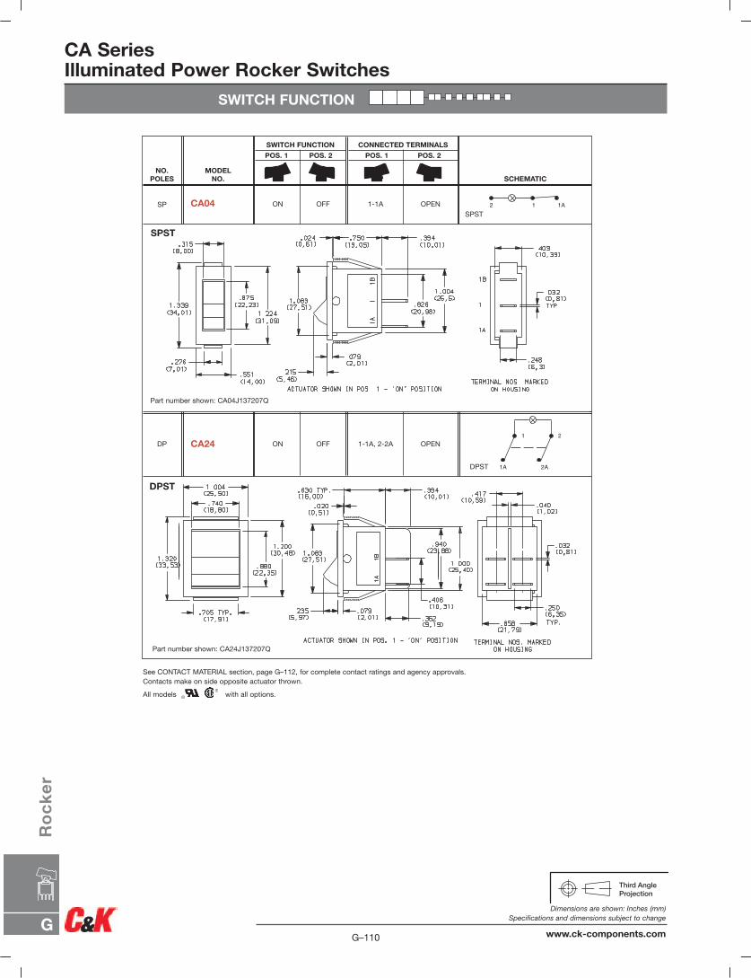
CA SeriesIlluminated Power Rocker Switches
SWITCH FUNCTION
DPST
OPEN1-1A, 2-2AOFFONCA24 DP
SPSTOPEN1-1AOFFONCA04 SP
SCHEMATIC
CONNECTED TERMINALS
POS. 1 POS. 2
SWITCH FUNCTION
POS. 1 POS. 2
MODEL NO.
NO.POLES
DPST
SPST
Part number shown: CA04J137207Q
Part number shown: CA24J137207Q
See CONTACT MATERIAL section, page G–112, for complete contact ratings and agency approvals.Contacts make on side opposite actuator thrown.
All models with all options.
1 1A2
1A
1
2A
2
G–110
Dimensions are shown: Inches (mm)Specifications and dimensions subject to change
www.ck-components.comG
Ro
ck
er
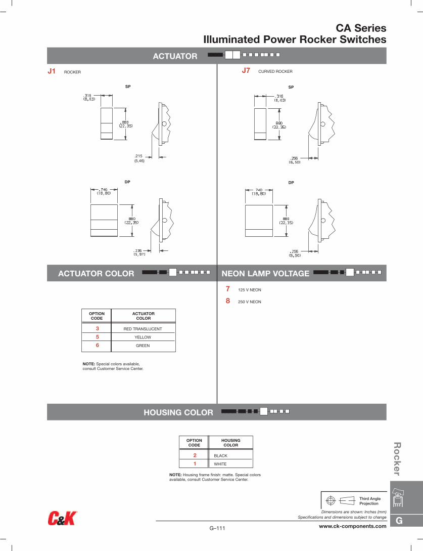
ACTUATOR
CA SeriesIlluminated Power Rocker Switches
SP
DP
.215(5,46)
SP
DP
J1 ROCKER J7 CURVED ROCKER
7 125 V NEON
8 250 V NEON
2 BLACK
1 WHITE
HOUSINGCOLOR
OPTION CODE
3 RED TRANSLUCENT
5 YELLOW
6 GREEN
ACTUATOR COLOR
OPTION CODE
NOTE: Housing frame finish: matte. Special colorsavailable, consult Customer Service Center.
NOTE: Special colors available,consult Customer Service Center.
ACTUATOR COLOR NEON LAMP VOLTAGE
HOUSING COLOR
G
Ro
ck
er
G–111
Dimensions are shown: Inches (mm)Specifications and dimensions subject to change
www.ck-components.com
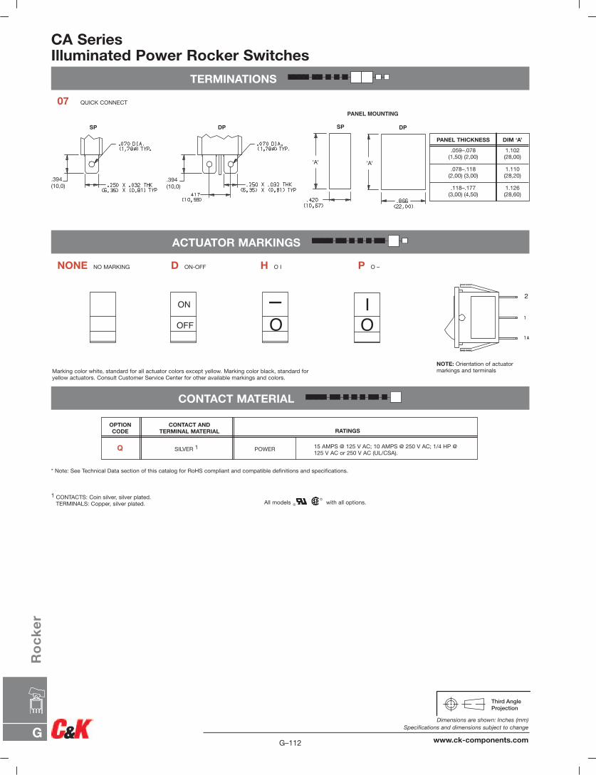
CA SeriesIlluminated Power Rocker Switches
TERMINATIONS
ACTUATOR MARKINGS
CONTACT MATERIAL
ON
OFF O
I 2
OI
SP DP
.394(10,0)
.394(10,0)
PANEL MOUNTING
SP DP
'A' 'A'
1.126(28,60)
.118–.177(3,00) (4,50)
1.110(28,20)
.078–.118(2,00) (3,00)
1.102(28,00)
.059–.078(1,50) (2,00)
DIM ‘A’PANEL THICKNESS
07 QUICK CONNECT
NONE NO MARKING D ON-OFF H O I P O –
1 CONTACTS: Coin silver, silver plated.TERMINALS: Copper, silver plated. All models with all options.
* Note: See Technical Data section of this catalog for RoHS compliant and compatible definitions and specifications.
Marking color white, standard for all actuator colors except yellow. Marking color black, standard foryellow actuators. Consult Customer Service Center for other available markings and colors.
NOTE: Orientation of actuator markings and terminals
15 AMPS @ 125 V AC; 10 AMPS @ 250 V AC; 1/4 HP @125 V AC or 250 V AC (UL/CSA).
RATINGSCONTACT AND
TERMINAL MATERIAL
SILVER 1 POWER
OPTION CODE
Q
G–112
Dimensions are shown: Inches (mm)Specifications and dimensions subject to change
www.ck-components.comG
Ro
ck
er