Embed Size (px)
Citation preview
Rock Slope StabilizationAMTRAK Harrisburg LineLancaster County, PA
Paul Deering, P.Eng, P.Geo, Stantec, St. John’s, NL, CARich Williams, PhD, PE, Stantec, Columbus, OH, US
Ohio Transportation Engineering Conference
Agenda
1Location / Background
2Project Scope
3 Investigation / Analysis
4Design
5Construction
6 Summary
Project location
Background information
1 Project Location / Background
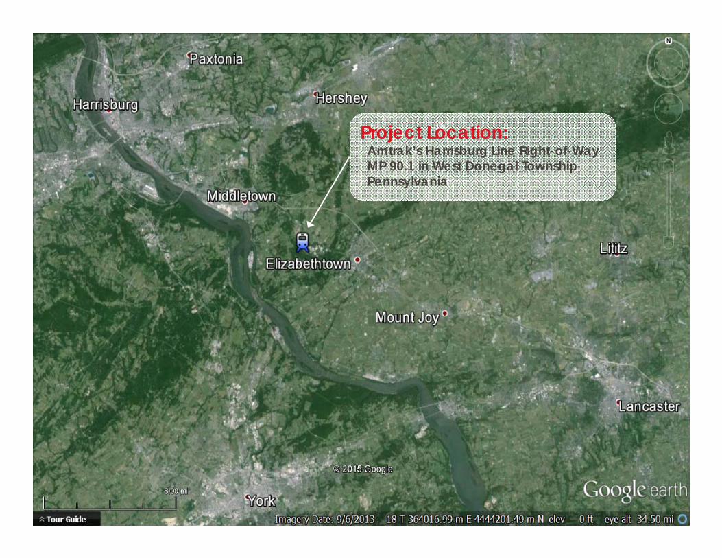
Project Location:Amtrak’s Harrisburg Line Right-of-Way MP 90.1 in West Donegal TownshipPennsylvania
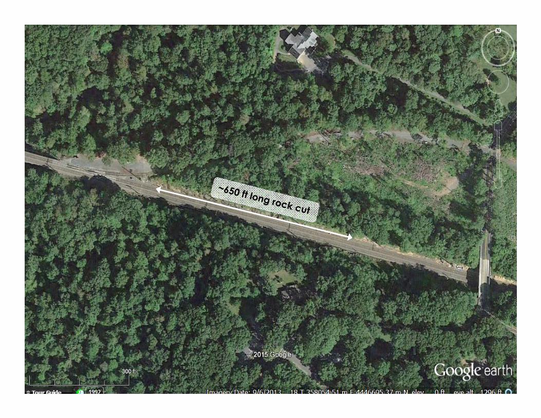
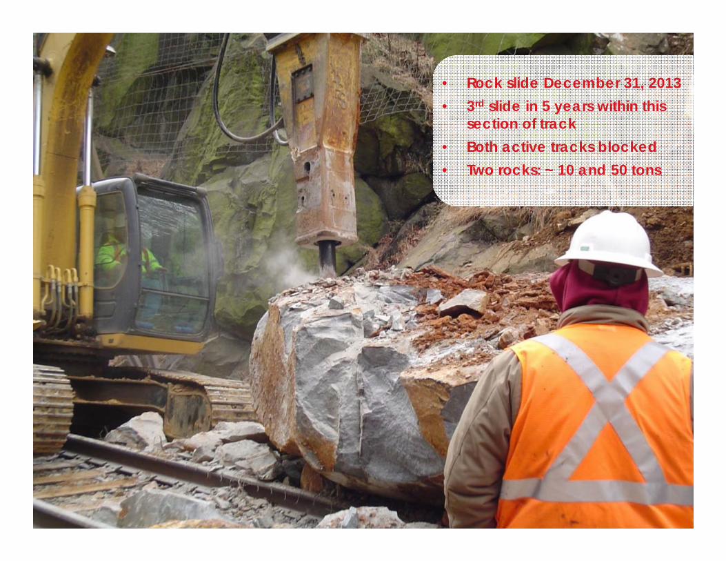
• Rock slide December 31, 2013 • 3rd slide in 5 years within this
section of track • Both active tracks blocked• Two rocks: ~ 10 and 50 tons
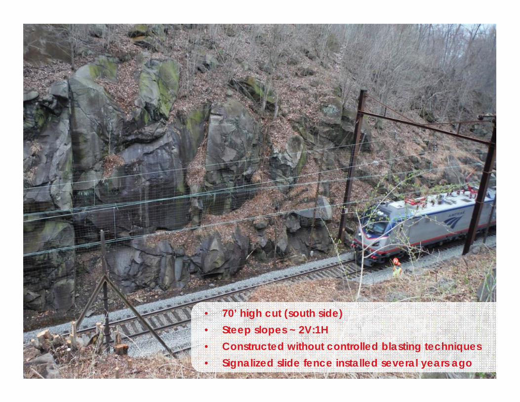
• 70’ high cut (south side) • Steep slopes ~ 2V:1H • Constructed without controlled blasting techniques • Signalized slide fence installed several years ago
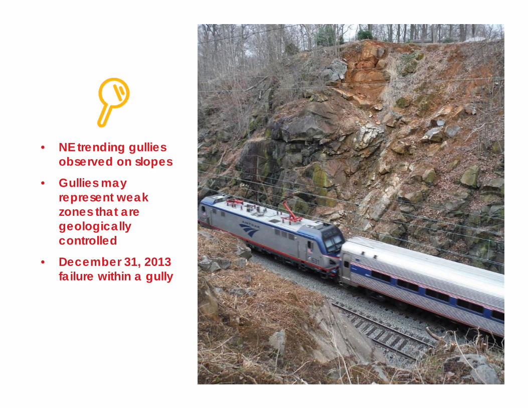
• NE trending gullies observed on slopes
• Gullies may represent weak zones that are geologically controlled
• December 31, 2013 failure within a gully
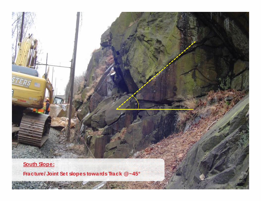
South Slope:
Fracture/Joint Set slopes towards Track @ ~45°
Investigation and Analysis
Design
Construction
2 Project Scope
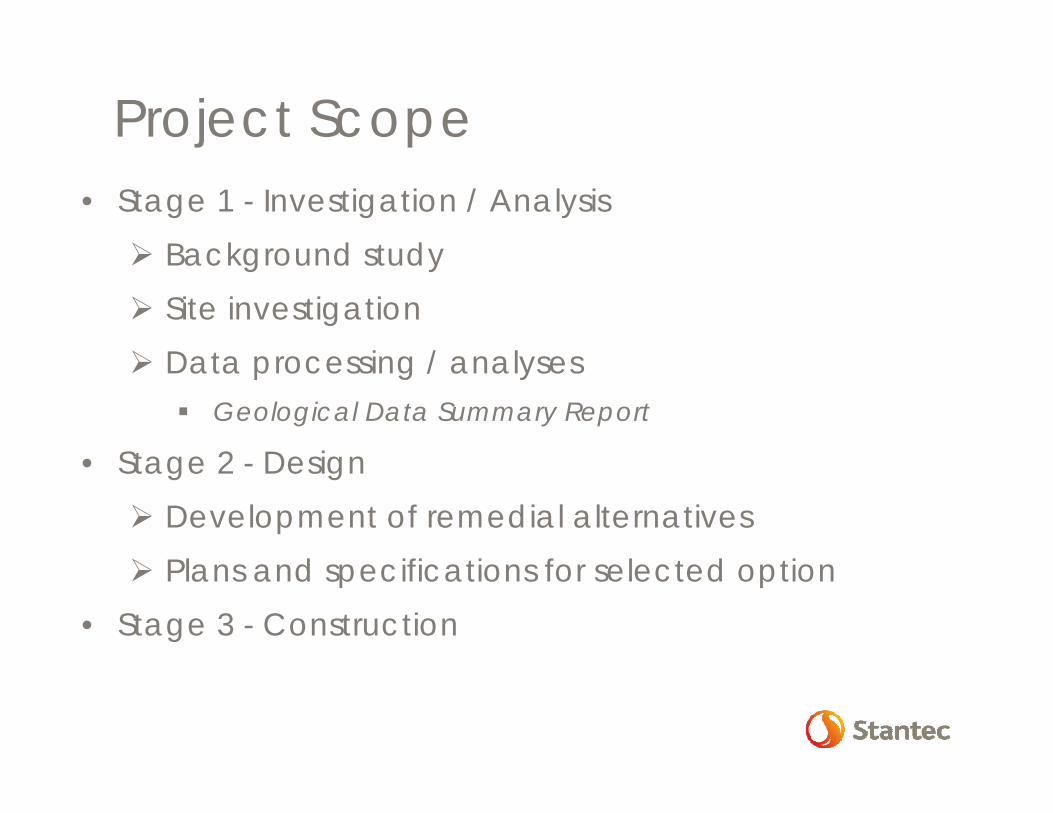
Project Scope• Stage 1 - Investigation / Analysis Background study Site investigation Data processing / analyses
Geological Data Summary Report
• Stage 2 - Design Development of remedial alternatives Plans and specifications for selected option
• Stage 3 - Construction
Investigation Surveying Geological Mapping Photogrammetry
Site Conditions
Analysis
3 Investigation and Analysis
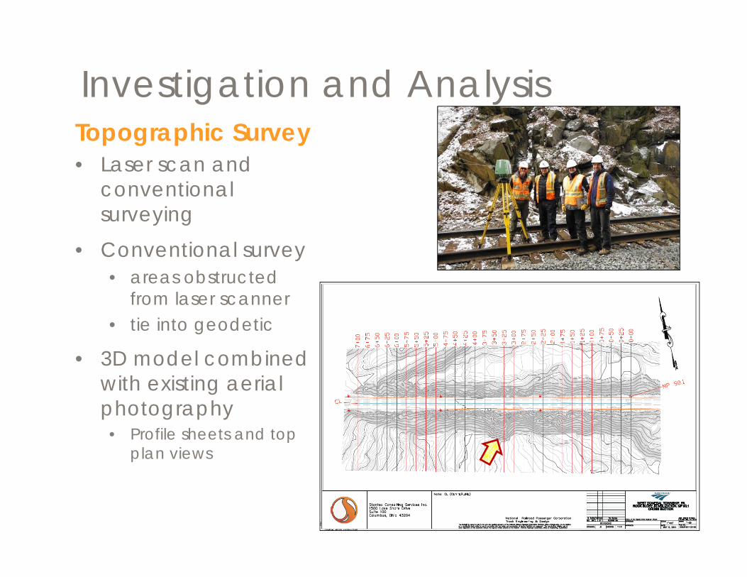
Investigation and AnalysisTopographic Survey• Laser scan and
conventional surveying
• Conventional survey • areas obstructed
from laser scanner• tie into geodetic
• 3D model combined with existing aerial photography • Profile sheets and top
plan views
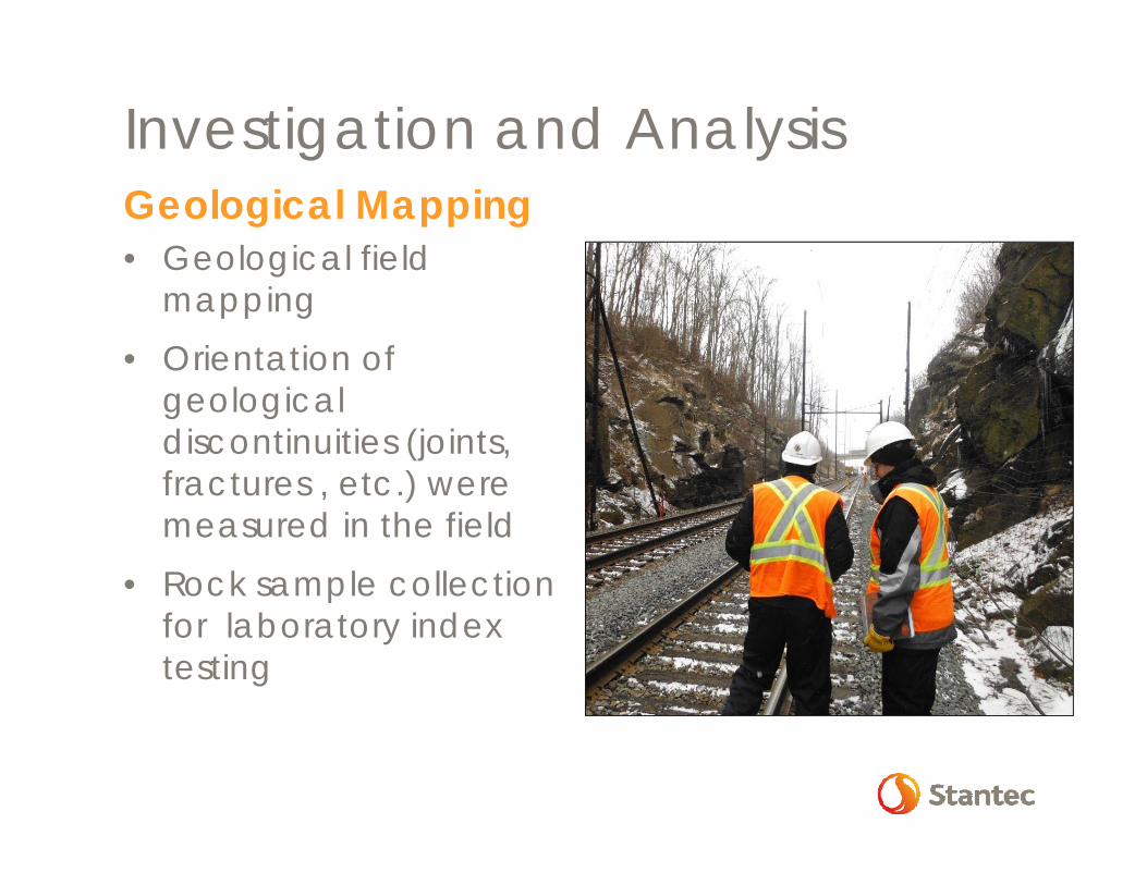
Investigation and AnalysisGeological Mapping• Geological field
mapping• Orientation of
geological discontinuities (joints, fractures , etc.) were measured in the field
• Rock sample collection for laboratory index testing
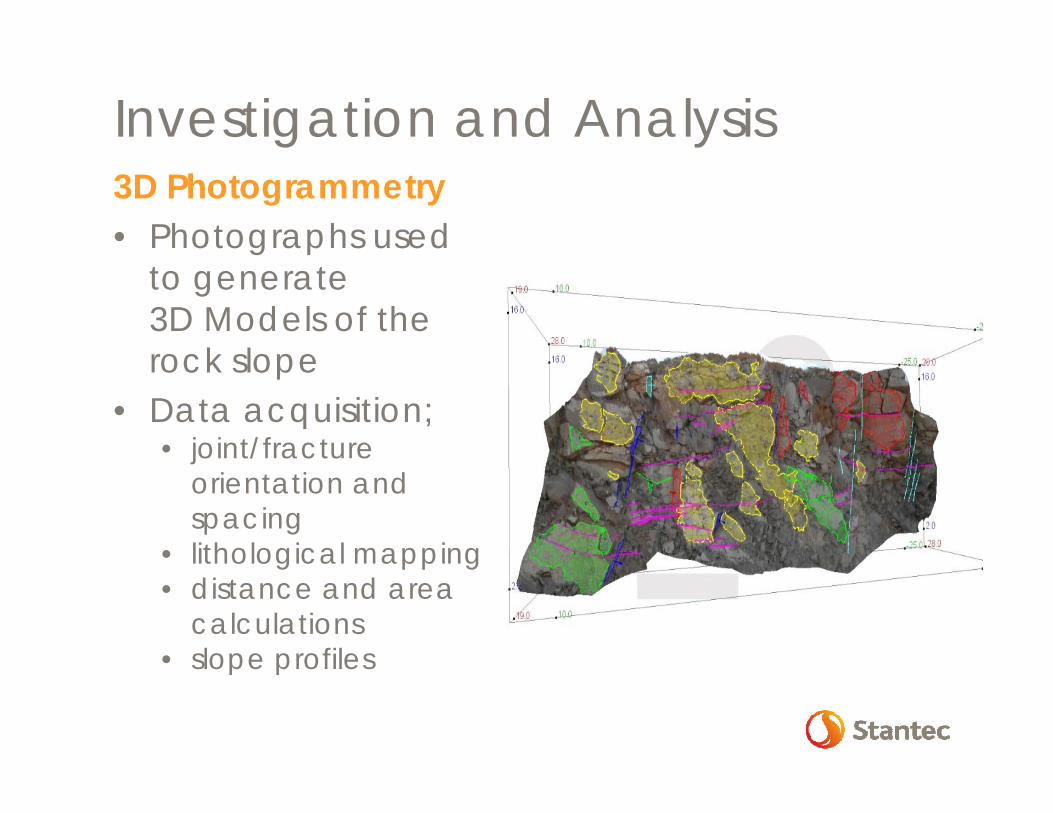
Investigation and Analysis3D Photogrammetry• Photographs used
to generate 3D Models of the rock slope
• Data acquisition; • joint/fracture
orientation and spacing
• lithological mapping• distance and area
calculations• slope profiles
Investigationand Analysis
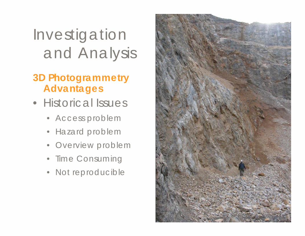
3D Photogrammetry Advantages
• Historical Issues• Access problem • Hazard problem• Overview problem• Time Consuming• Not reproducible
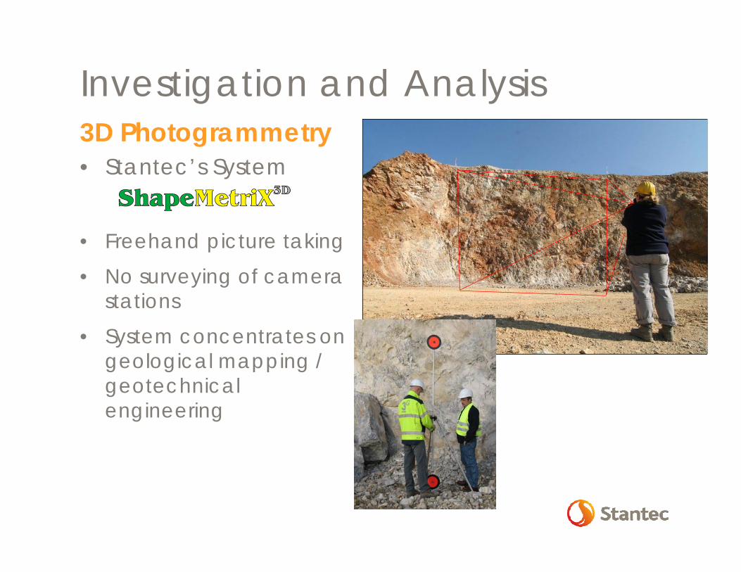
Investigation and Analysis3D Photogrammetry• Stantec’s System
• Freehand picture taking
• No surveying of camera stations
• System concentrates on geological mapping / geotechnical engineering
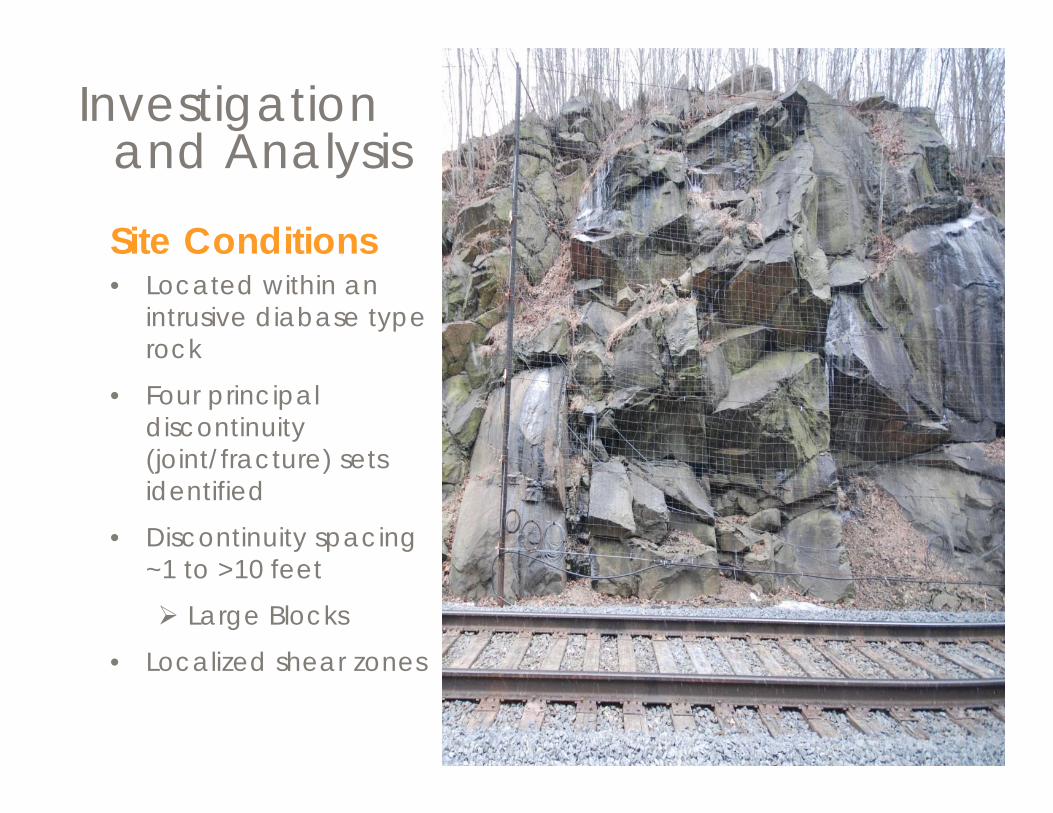
Site Conditions• Located within an
intrusive diabase type rock
• Four principal discontinuity (joint/fracture) sets identified
• Discontinuity spacing ~1 to >10 feet
Large Blocks
• Localized shear zones
Investigation and Analysis
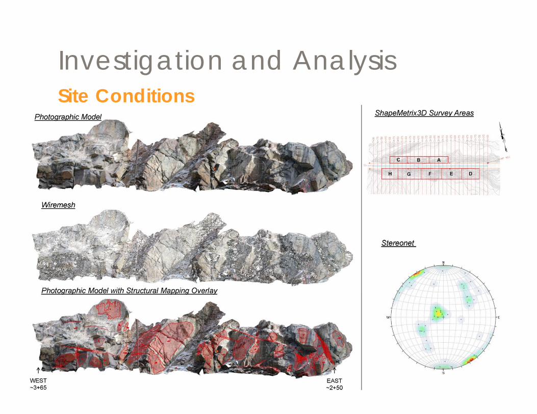
Investigation and AnalysisSite Conditions
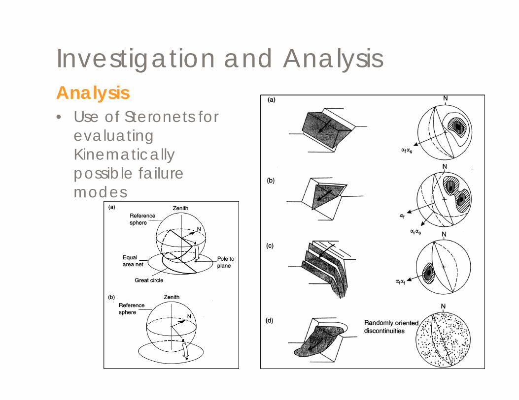
Investigation and AnalysisAnalysis• Use of Steronets for
evaluating Kinematicallypossible failure modes
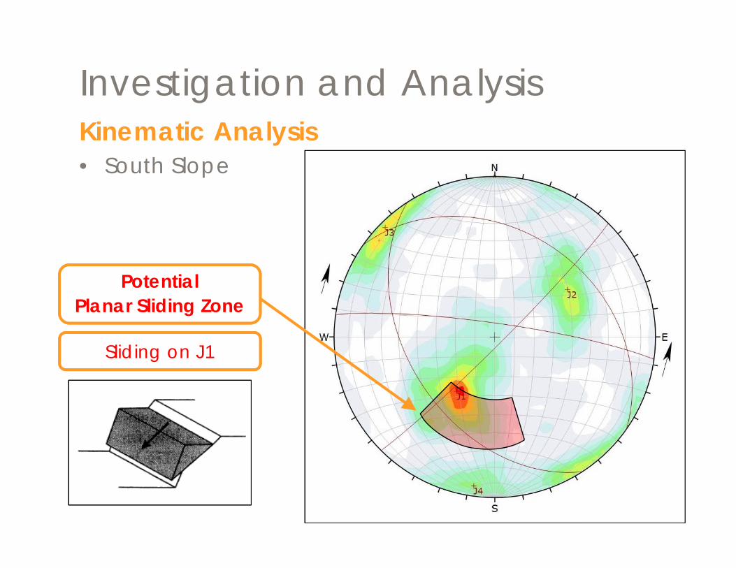
Investigation and AnalysisKinematic Analysis• South Slope
Potential Planar Sliding Zone
Sliding on J1
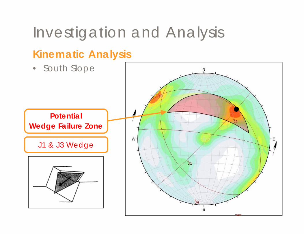
Investigation and AnalysisKinematic Analysis• South Slope
Potential Wedge Failure Zone
J1 & J3 Wedge
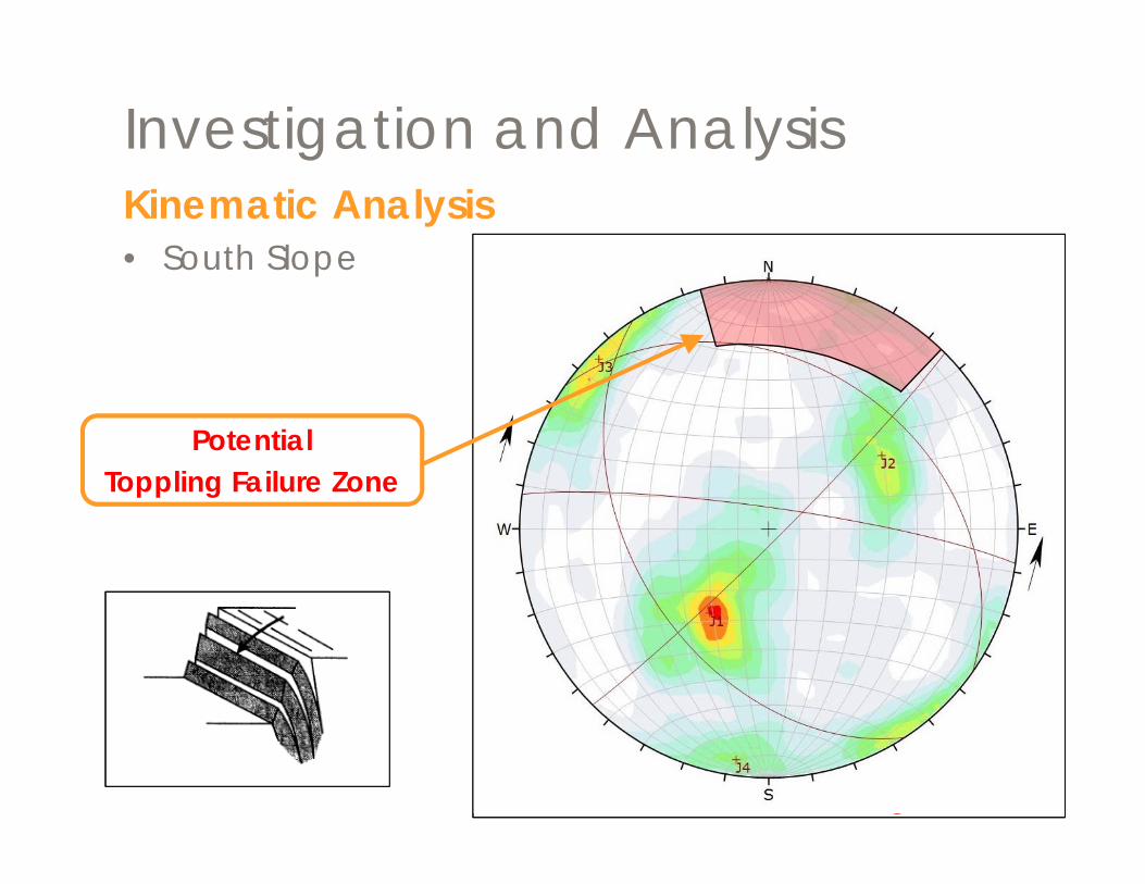
Investigation and AnalysisKinematic Analysis• South Slope
Potential Toppling Failure Zone
Investigation and Analysis
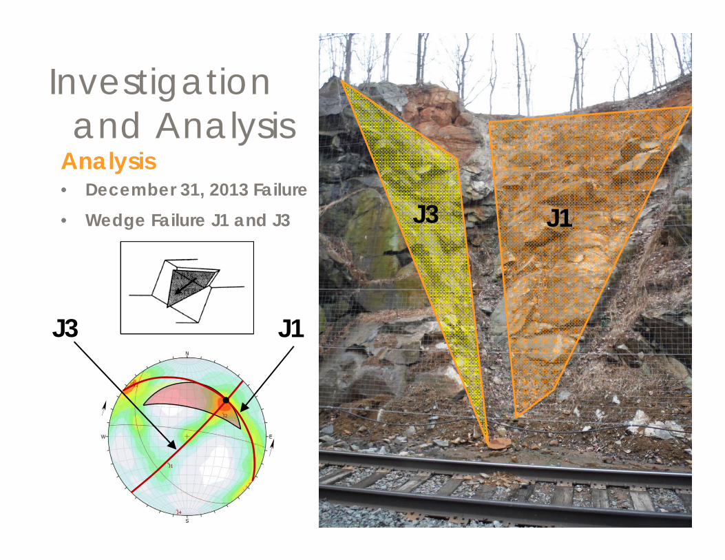
Analysis• December 31, 2013 Failure• Wedge Failure J1 and J3 J3
J3
J1
J1
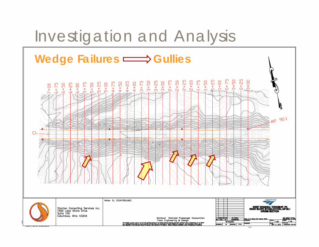
Investigation and AnalysisWedge Failures Gullies
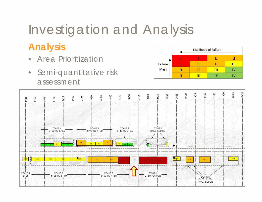
Investigation and AnalysisAnalysis• Area Prioritization• Semi-quantitative risk
assessment
Development of remedial alternatives
Plans and specifications for selected option
4 Design
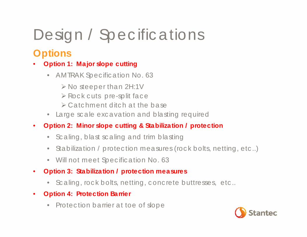
Options• Option 1: Major slope cutting
• AMTRAK Specification No. 63No steeper than 2H:1V Rock cuts pre-split faceCatchment ditch at the base
• Large scale excavation and blasting required• Option 2: Minor slope cutting & Stabilization / protection
• Scaling, blast scaling and trim blasting• Stabilization / protection measures (rock bolts, netting, etc..) • Will not meet Specification No. 63
• Option 3: Stabilization / protection measures• Scaling, rock bolts, netting, concrete buttresses, etc..
• Option 4: Protection Barrier • Protection barrier at toe of slope
Design / Specifications
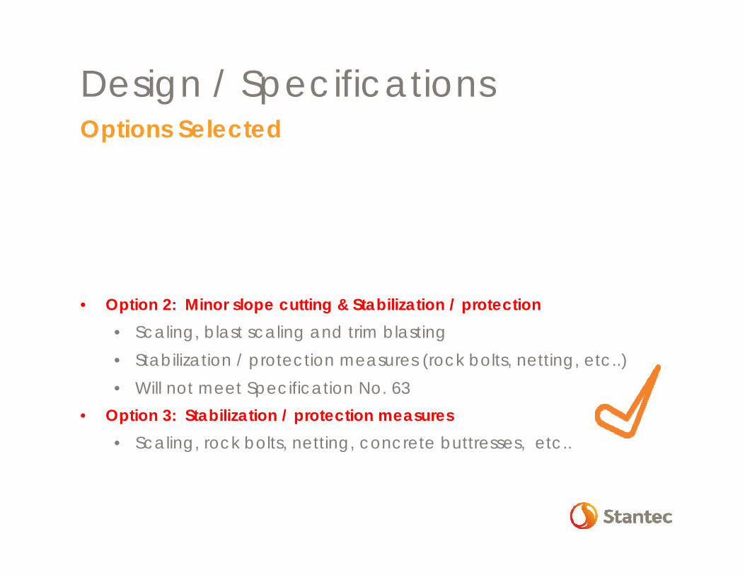
Options Selected• Option 1: Major slope cutting
• AMTRAK Specification No. 63No steeper than 2H:1V Rock cuts pre-split faceCatchment ditch at the base
• Large scale excavation and blasting required• Option 2: Minor slope cutting & Stabilization / protection
• Scaling, blast scaling and trim blasting• Stabilization / protection measures (rock bolts, netting, etc..) • Will not meet Specification No. 63
• Option 3: Stabilization / protection measures• Scaling, rock bolts, netting, concrete buttresses, etc..
• Option 4: Protection Barrier • Protection barrier at toe of slope
Design / Specifications
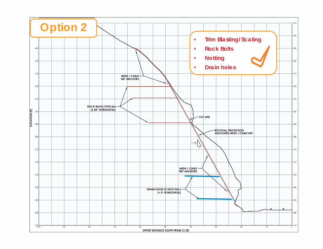
• Trim Blasting/Scaling• Rock Bolts• Netting• Drain holes
Option 2
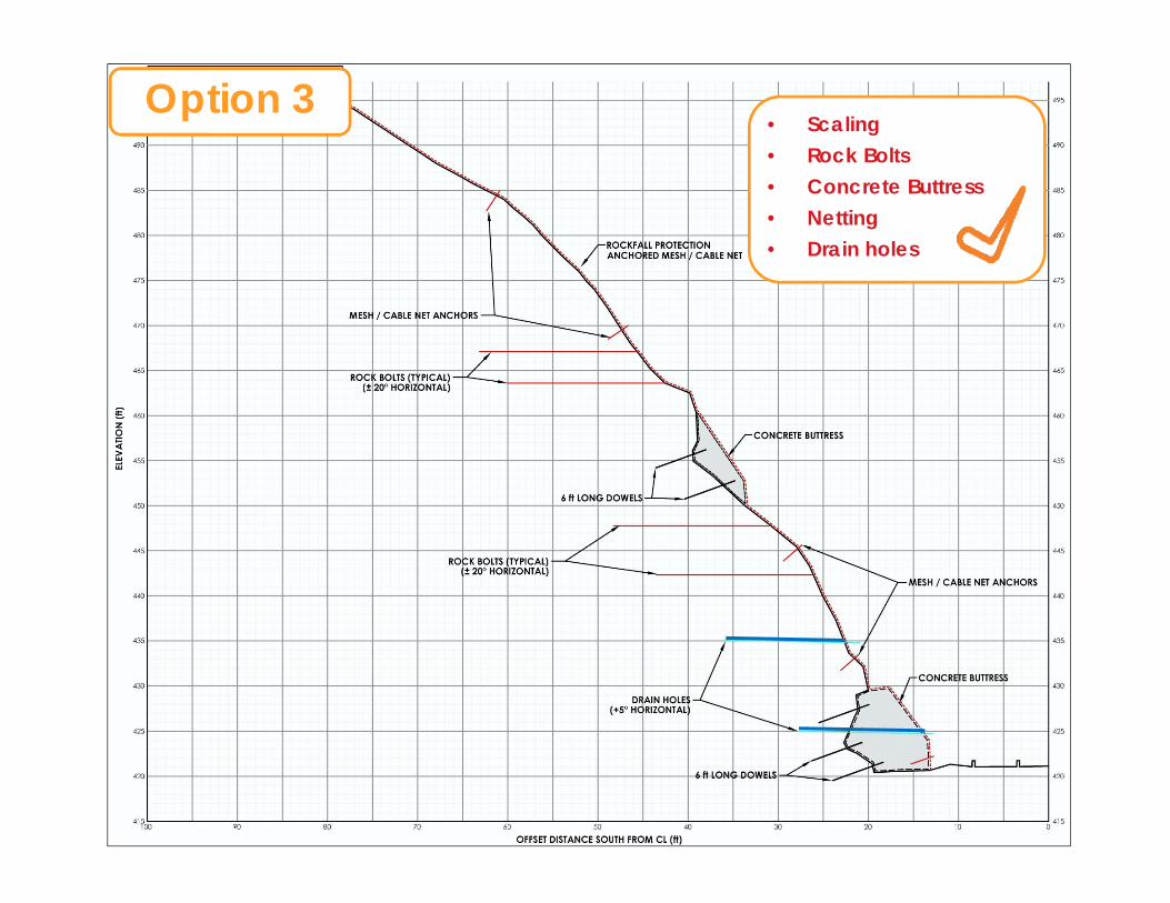
Option 3• Scaling• Rock Bolts• Concrete Buttress • Netting• Drain holes
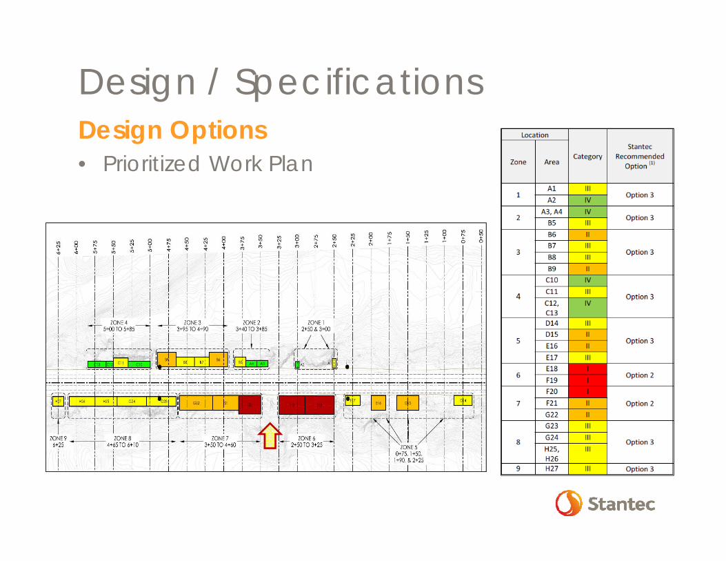
Design Options• Prioritized Work Plan
Design / Specifications
• Communication with Client/Owner• design philosophy• design limitations
• Estimating quantities• notoriously difficult to estimate accurately during design
stage
• Site conditions during construction• conditions will likely be encountered requiring field
assessment and potential design modifications.• quantity estimates should accommodate this philosophy
• Contractual language • to allow change in quantities without incurring penalties or
cost premiums
Design / Specifications
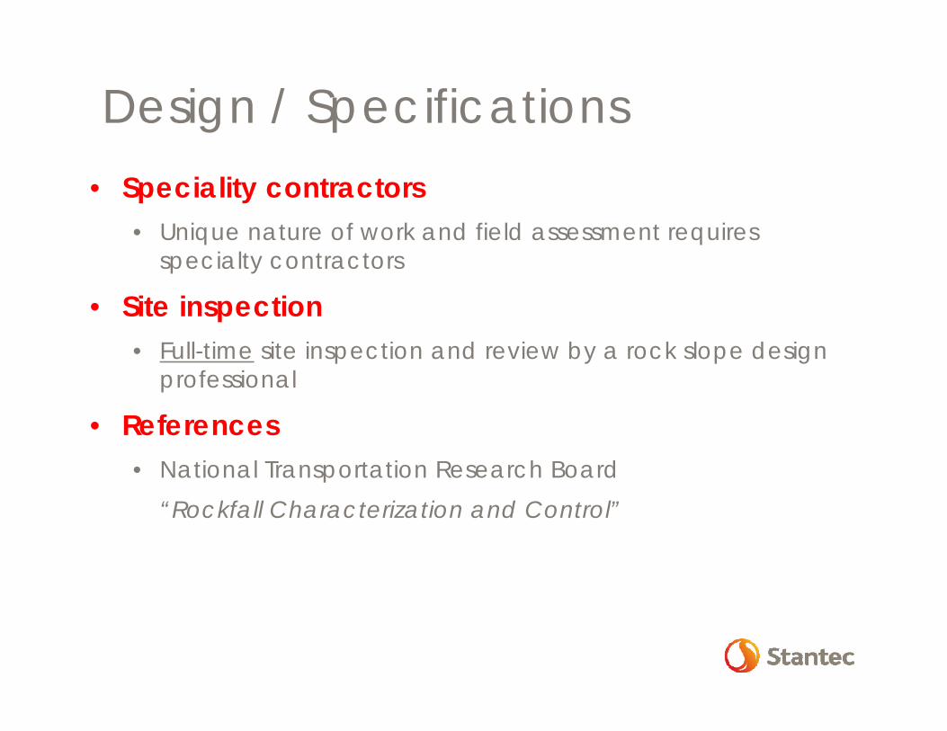
Design / Specifications• Speciality contractors
• Unique nature of work and field assessment requires specialty contractors
• Site inspection• Full-time site inspection and review by a rock slope design
professional
• References• National Transportation Research Board
“Rockfall Characterization and Control”
Scaling
Rock Bolts
Concrete Buttress
Netting
5 Construction
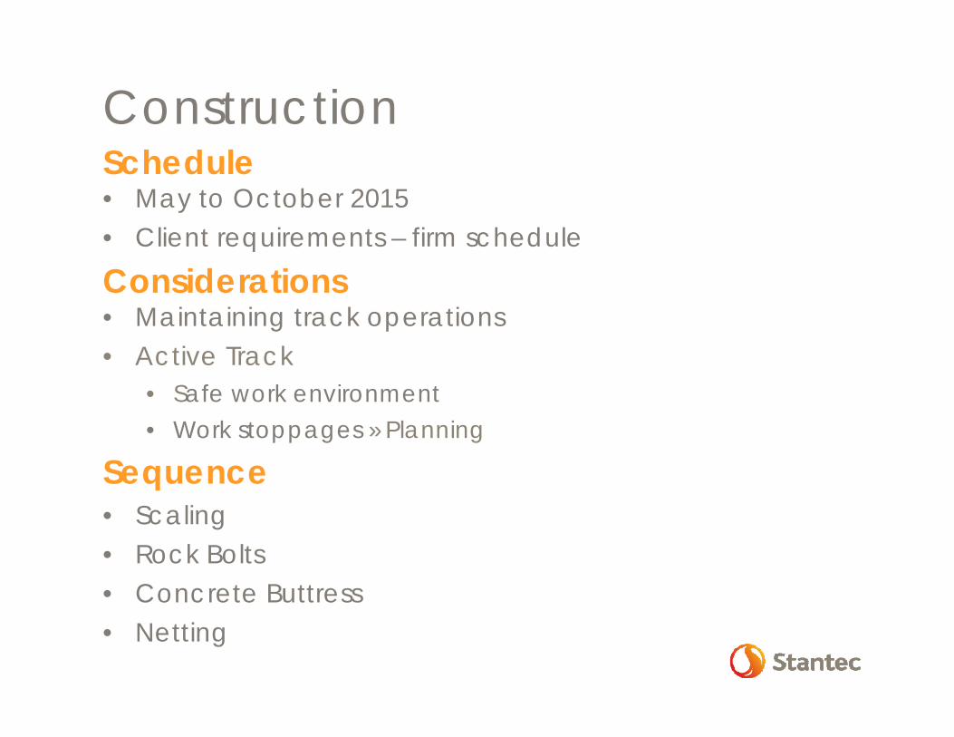
ConstructionSchedule• May to October 2015• Client requirements – firm schedule
Considerations• Maintaining track operations• Active Track
• Safe work environment• Work stoppages » Planning
Sequence• Scaling• Rock Bolts• Concrete Buttress• Netting
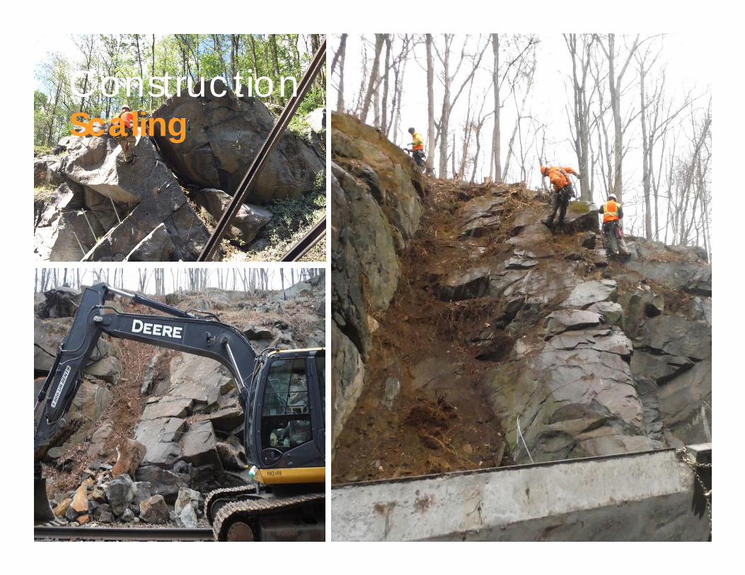
ConstructionScaling
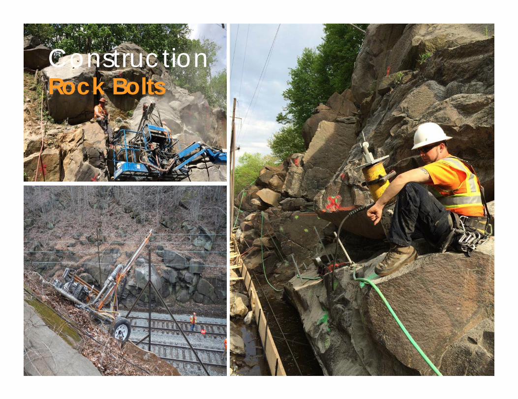
ConstructionRock Bolts
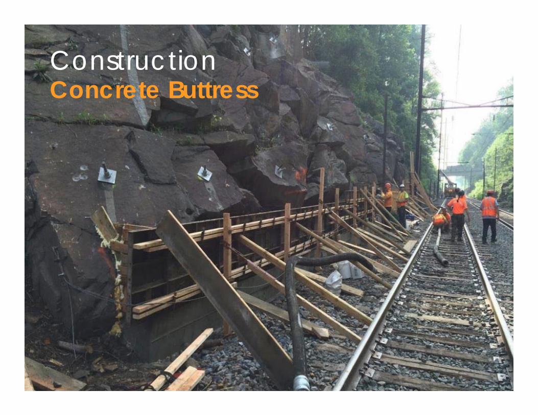
ConstructionConcrete Buttress
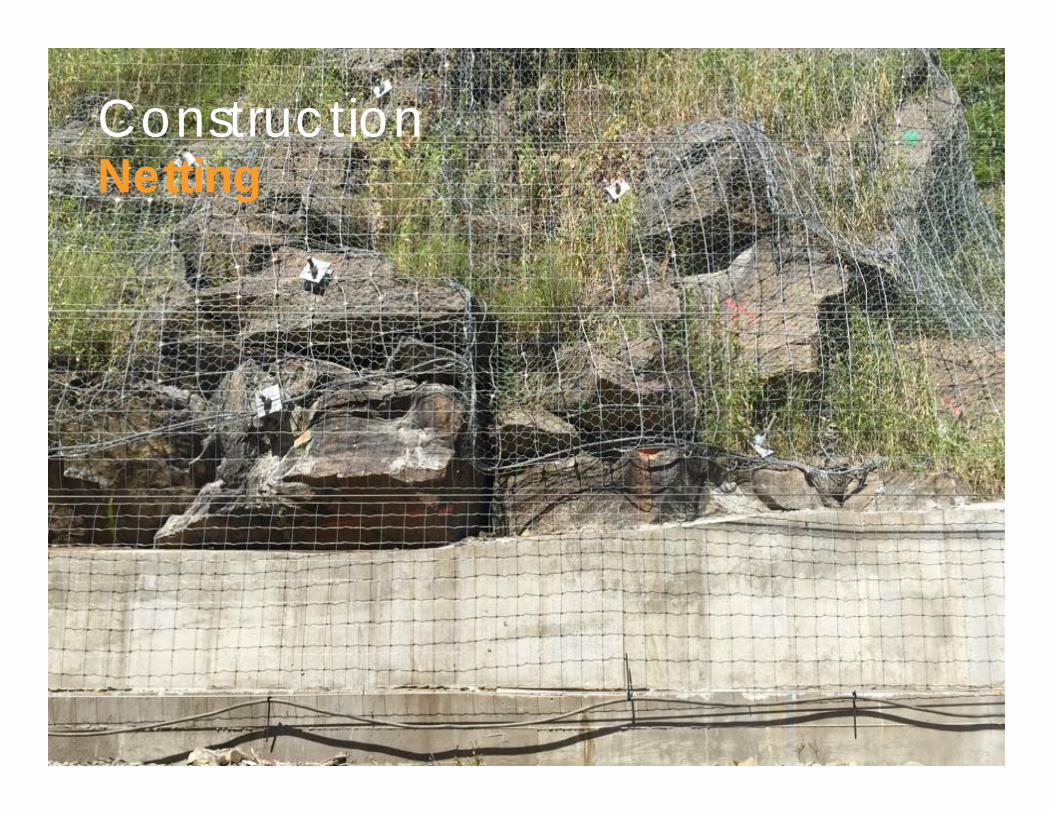
ConstructionNetting
Technical
Design
Construction
6 Summary
Summary
• Technical• Rock slopes » hazards along transportation
corridors• 3D Photogrammetry advantages
• Safe, Accurate, Fast
• Geological model defines failure modes• Failure modes determine design• Risk assessment » priority areas
Summary
• Design• Communication with Client/Owner
• Design philosophy• Design limitations• Design options
• Quantities are difficult to estimate accurately
• Expect design modifications during construction
Summary
• Construction• Restrictions/limitations » Transportation
corridors• Specialty contractors required• Full-time engineering site inspection
Stantec Team• Maureen Matthew• John Nichols
Acknowledgments
Stantec appreciates the opportunity to serve the National Railroad Passenger Corporation (AMTRAK) on this project
Acknowledgments

thank you
questions?