Embed Size (px)
Citation preview
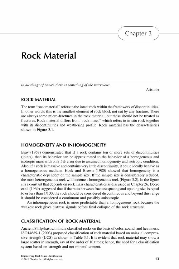
Chapter 3
Rock Material
In all things of nature there is something of the marvelous.Aristotle
ROCK MATERIAL
The term “rockmaterial” refers to the intact rock within the framework of discontinuities.In other words, this is the smallest element of rock block not cut by any fracture. Thereare always some micro-fractures in the rock material, but these should not be treated asfractures. Rock material differs from “rock mass,” which refers to in situ rock togetherwith its discontinuities and weathering profile. Rock material has the characteristicsshown in Figure 3.1.
HOMOGENEITY AND INHOMOGENEITY
Bray (1967) demonstrated that if a rock contains ten or more sets of discontinuities(joints), then its behavior can be approximated to the behavior of a homogeneous andisotropic mass with only 5% error due to assumed homogeneity and isotropic condition.Also, if a rock is massive and contains very little discontinuity, it could ideally behave asa homogeneous medium. Hoek and Brown (1980) showed that homogeneity is acharacteristic dependent on the sample size. If the sample size is considerably reduced,the most heterogeneous rock will become a homogeneous rock (Figure 3.2). In the figures is a constant that depends on rockmass characteristics as discussed in Chapter 26. Deereet al. (1969) suggested that if the ratio between fracture spacing and opening size is equalto or less than 1/100, the rock should be considered discontinuous and beyond this rangeit should be considered a continuum and possibly anisotropic.
An inhomogeneous rock is more predictable than a homogeneous rock because theweakest rock gives distress signals before final collapse of the rock structure.
CLASSIFICATION OF ROCK MATERIAL
Ancient Shilpshastra in India classified rocks on the basis of color, sound, and heaviness.ISO14689-1 (2003) proposed classification of rock material based on uniaxial compres-sive strength (UCS) as shown in Table 3.1. It is evident that rock material may show alarge scatter in strength, say of the order of 10 times; hence, the need for a classificationsystem based on strength and not mineral content.
Engineering Rock Mass Classification# 2011 Elsevier Inc. All rights reserved. 13

FIGURE 3.2 Rock mass conditions under the Hoek-Brown failure criterion. (From Hoek, 1994)
FIGURE 3.1 Material characteristics of rocks.
Engineering Rock Mass Classification14
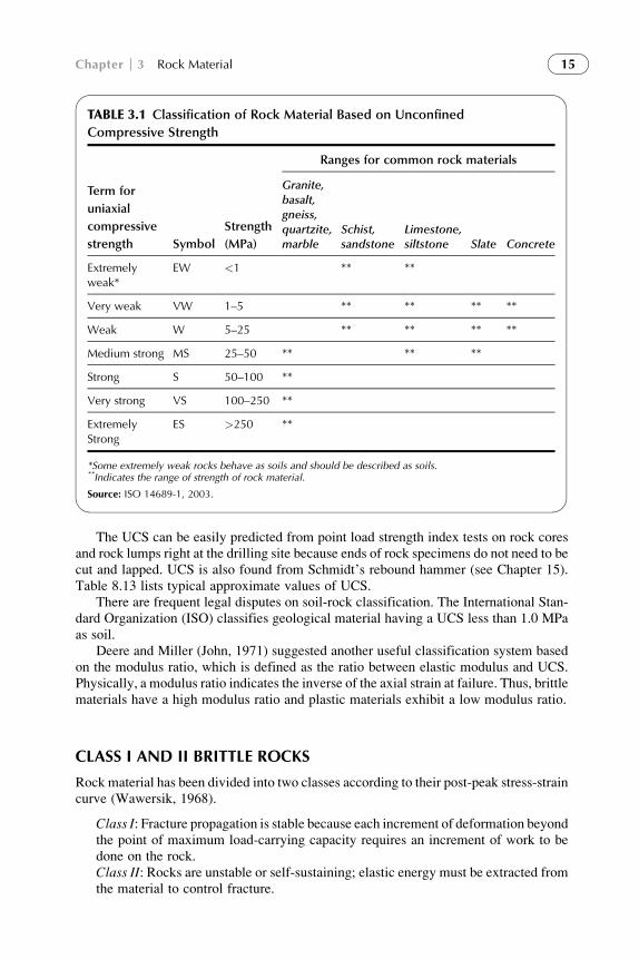
The UCS can be easily predicted from point load strength index tests on rock coresand rock lumps right at the drilling site because ends of rock specimens do not need to becut and lapped. UCS is also found from Schmidt’s rebound hammer (see Chapter 15).Table 8.13 lists typical approximate values of UCS.
There are frequent legal disputes on soil-rock classification. The International Stan-dard Organization (ISO) classifies geological material having a UCS less than 1.0 MPaas soil.
Deere and Miller (John, 1971) suggested another useful classification system basedon the modulus ratio, which is defined as the ratio between elastic modulus and UCS.Physically, a modulus ratio indicates the inverse of the axial strain at failure. Thus, brittlematerials have a high modulus ratio and plastic materials exhibit a low modulus ratio.
CLASS I AND II BRITTLE ROCKS
Rock material has been divided into two classes according to their post-peak stress-straincurve (Wawersik, 1968).
Class I: Fracture propagation is stable because each increment of deformation beyondthe point of maximum load-carrying capacity requires an increment of work to bedone on the rock.Class II: Rocks are unstable or self-sustaining; elastic energy must be extracted fromthe material to control fracture.
TABLE 3.1 Classification of Rock Material Based on Unconfined
Compressive Strength
Term for
uniaxial
compressive
strength Symbol
Strength
(MPa)
Ranges for common rock materials
Granite,basalt,gneiss,quartzite,marble
Schist,sandstone
Limestone,siltstone Slate Concrete
Extremelyweak*
EW <1 ** **
Very weak VW 1–5 ** ** ** **
Weak W 5–25 ** ** ** **
Medium strong MS 25–50 ** ** **
Strong S 50–100 **
Very strong VS 100–250 **
ExtremelyStrong
ES >250 **
*Some extremely weak rocks behave as soils and should be described as soils.**Indicates the range of strength of rock material.
Source: ISO 14689-1, 2003.
Chapter 3 Rock Material 15

The introduction of partial confinement, as in short samples when end constraintbecomes prominent, is likely to have a satisfactory effect. If end restraint becomessevere, it is possible that a Class II rock might behave like a Class I material.
Wawersik (1968) conducted experiments on six rock types to demonstrate thefeatures of Class I and II rocks (Figure 3.3). Typical S-shape stress-strain curves maybe obtained for rocks with micro-fractures. Further, the post-peak curve for Class II rocksshows reduction of strain after failure. The lateral strain increases rapidly after peakstress in Class II rocks. Brittle rocks, therefore, may be kept in the Class II category.
A deep tunnel within dry, massive, hard Class II and laminated rocks may failbecause of rock bursts due to uncontrolled fracturing where tangential stress exceedsthe strength of the rock material (see Chapter 13). Hence, it is necessary to test rockmaterial in a Servo-controlled closed loop testing machine to get the post-peak curve.
UNIAXIAL COMPRESSION
Rock failure in uniaxial compression occurs in two modes: (1) local (axial) splitting orcleavage failure parallel to the applied stress, and (2) shear failure.
FIGURE 3.3 Stress-strain curves for six representative rocks in uniaxial compression. (FromWawersik, 1968)
Engineering Rock Mass Classification16

Local cleavage fracture characterizes fracture initiation at 50 to 95%of the compressivestrength and is continuous throughout the entire loading history. Axial cleavage fracture is alocal stress-relievingphenomenon that depends on the strength anisotropy and brittleness ofthe crystalline aggregates as well as on the grain size of the rock. Local axial splitting isvirtually absent in fine-grained materials at stress levels below their compressive strength.
Shear failure manifests in the development of boundary faults (followed by interiorfractures), which are oriented at approximately 30 degrees to the sample axis. In fine-grained materials where the inhomogeneity of the stress distribution depends only onthe initial matching of the material properties at the loading platen interfaces, boundaryand interior faults are likely to develop simultaneously and appear to have the sameorientation for any rock type within the accuracy of the measurements on the remnantpieces of collapsed specimens (basalts, etc.).
Local axial fracturing governs the maximum load-carrying ability of coarse-grained,locally inhomogeneous Class I and II rock types. Thus, in coarse-grained rocks theultimate macroscopic failure mode of fully collapsed samples in uniform uniaxial com-pression cannot be related to peak stress. In fine-grained, locally homogeneous rocktypes, which most likely are Class II, the peak stress is probably characterized by thedevelopment of shear fractures seen in continuous failure planes. In controlled fractureexperiments on very fine-grained rocks, the final appearance of a collapsed rock spec-imen probably correlates with its compressive strength. However, if rock fracture isuncontrolled, then the effects of stress waves produced by the dynamic release of energymay override the quasi-elastic failure phenomenon to such an extent that the latter mayno longer be recognizable.
The extent of the development of the twobasic failuremodes, local axial splitting and slipor shear failure, determines the shape of the stress-strain curve for all rocks subjected to uni-directional or triaxial loading. Partially failed rocks still exhibit elastic properties. However,the sample stiffness decreases steadily with increasing deformation and loss of strength.
Macroscopic cleavage failure (e.g., laboratory samples splitting axially into two ormore segments) was never observed in the experiments on Class I and II rocks. Anapproximate theoretical analysis of the “sliding surface” model, which was proposedby Fairhurst and Cook (1966), revealed qualitatively that unstable axial cleavage fractureis an unlikely failure mode of rocks in uniaxial compression.
The dynamic tensile strength of rocks (granite, diorite, limestone, and grigen) isfound to be about four to five times the static tensile strength (Mohanty, 2009). Braziliantensile strength of laminated rocks and other argillaceous weak rocks like marl do notappear to be related to the UCS of rock material (Constantin, personal communication).
STABILITY IN WATER
Inhydroelectricprojects, rocksarechargedwithwater.Thepotential fordisintegrationof rockmaterial in water can be determined by immersing rock pieces in water for up to oneweek.Their stability canbedescribedusing the terms listed inTable 3.2 (ISO14689-1, 2003).
Ultrasonic pulse velocity in a saturated rock is higher than in a dry rock because it iseasier for pulse to travel through water than in air voids. However, the UCS and modulusof elasticity are reduced significantly after saturation, particularly in rocks with watersensitive minerals. On the other hand, the post-peak stress-strain curve becomes flatterin the case of undrained UCS tests on saturated samples because increasing fractureporosity after failure creates negative pore water pressure.
Chapter 3 Rock Material 17

CLASSIFICATION ON THE BASIS OF SLAKE DURABILITY INDEX
Based upon his tests on representative shales and clay stones for two 10-minute cyclesafter drying, Gamble (1971) found the slake durability index varied from 0 to 100%.There are no visible connections between durability and geological age, but durabilityincreased linearly with density and inversely with natural water content. Based on hisresults, Gamble proposed a classification of slake durability as seen in Table 3.3.The slake durability classification is useful when selecting rock aggregates for road, railline, concrete, and shotcrete.
Rock in field is generally jointed. It was classified by core recovery in the past andlater in the 1960s by modified core recovery (RQD), which will be discussed inChapter 4.
TABLE 3.2 Rock Material Stability in Water
Term Description (after 24 h in water) Grade
Stable No changes 1
Fairly stable A few fissures are formed or specimen surface crumbles slightly 2
Many fissures are formed and broken into small lumps orspecimen surface crumbles
3
Unstable Specimen disintegrates or nearly the whole specimen surfacecrumbles
4
The whole specimen becomes muddy or disintegrates into sand 5
Source: ISO 14689-1, 2003.
TABLE 3.3 Slake Durability Classification
Group name
% retained after one
10-minute cycle
(dry weight basis)
% retained after two
10-minute cycles
(dry weight basis)
Very high durability >99 >98
High durability 98–99 95–98
Medium high durability 95–98 85–95
Medium durability 85–95 60–85
Low durability 60–85 30–60
Very low durability <60 <30
Source: Gamble, 1971, 2003.
Engineering Rock Mass Classification18

REFERENCES
Bray, J. W. (1967). A study of jointed and fractured rock. Part I. Rock Mechanics and Engineering
Geology, 5–6(2–3), 117–136.
Deere, D. U., Peck, R. B., Monsees, J. E., & Schmidt, B. (1969). Design of tunnel liners and support
system (Final Report, University of Illinois, Urbana, for Office of High Speed Transportation,
Contract No. 3-0152, p. 404). Washington, D.C.: U.S. Department of Transportation.
Fairhurst, C., & Cook, N. G. W. (1966). The phenomenon of rock splitting parallel to the direction of
maximum compression in the neighborhood of a surface. In: Proceedings 1st Congress, International
Society of Rock Mechanics, Lisbon, pp. 687–692.
Gamble, J. C. (1971).Durability—Plasticity classification of shales and other argillaceous rocks (p. 159).
Ph.D. Thesis. University of Illinois.
Hoek, E. (1994). Strength of rock and rock masses. ISRM News Journal, 2(2), 4–16.
Hoek, E., & Brown, E. T. (1980). Underground excavations in rocks. Institution of Mining and
Metallurgy (p. 527). London: Maney Publishing.
ISO14689-1 (2003). (E).Geotechnical investigation and testing—Identification and classification of rock—
Part 1: Identification and description (pp. 1–16). Geneva: International Organization for
Standardization.
Mohanty, B. (2009). Measurement of dynamic tensile strength in rock by means of explosive-driven
Hopkinson bar method. In Workshop on Rock Dynamics, ISRM Commission on Rock Dynamics.
Lausanne, Switzerland: EPFL, June.
Wawersik, W. R. (1968). Detailed analysis of rock failure in laboratory compression tests (p. 165).
Ph.D. Thesis. University of Minnesota.
Chapter 3 Rock Material 19