Embed Size (px)
Citation preview
In: Fracture of Rock. Chapter 6. Ed. M.H. Aliabadi.Computational Mechanics Publications. 1998. pp. 167-203.
Chapter 6
Rock fragmentation and optimization of drilling toolsL. Mishnaevsky JrMPA, University of Stuttgart, Pfaffenwaldring 32D- 70569 Stuttgart, GermanyEmail: [email protected]
Abstract
In this chapter possibilities of the improvement of drilling tool efficiency on the basis of theanalysis of mechanisms of rock destruction and some methods of the information theory areconsidered. Physical mechanisms of destruction of hard and plastic rocks under differentconditions of mechanical loading are reviewed. Some physical effects which allow to improve theefficiency of rock drilling tool are listed and ways of tool improvement are discussed. It is shownexperimentally that the efficiency of drilling by a multicutter drilling tool may be improved byusing the interaction between crack systems from neighboring cuts. It was suggested to applymethods of the theory of information to model complex processes of rock destruction androck/tool interaction. Several examples of using of the information theory methods are given(stress distribution in disordered rocks, indexing effect, tool wear, optimization of complex toolconstruction). The general principle of tool improvement is formulated on the basis of theinformational models.
1 Introduction
Tools for mechanical destruction of rocks are used on almost al1 stages and processes of mining.The improvement of the efficiency of destructing tools is one of most important sources of theimprovement of mining and is therefore among first areas of application of the fracture mechanicsof rocks. In this work, the following problems are treated: mechanisms of rock fracture undermechanical loading (how it proceeds in simplest and not so simple cases), rock cutting, physicaleffects which can be used to improve the destructing tool, limitations of tool improvement ( themain of them is the tool wear) and some advanced methods of the rock destruction model1ing andthe improvement of rock breaking tool.
Fracture of Rock168
Some materials from [2,9, 23, 26] are used and the Table 2 from [26] is re- printed here withkind permission from Elsevier Science Ltd, UK.
2 Damage and Fracture under Mechanical Loading
Consider first the mechanism of rock fragmentation under indentation of axisymmetric indenter into asurface of elastobrittle rock. The destruction of rock under the indenter proceeds as follows [1-3]: firstly,the rock in the vicinity of contact surface is deformed and small surface cracks or microcracks appear alayer of destructed rock is formed under the contact surface and then the layer is crushed thereafter, thevolume destruction of rock begins. A zone of inelastic deformation is formed under contact surface ( thiszone corresponds to the area of hydrostatic pressure) and the Hertzian cone crack initiates and grows. Therock in the zone of hydrostatic pressure under the indenter is destructed mainly through local shears andthen powdered. The destructed rock under the indenter begins to expand and transmits the load to the restof rock. Thereafter, the volume of rock bounded by the cone crack is failed and the axial cracks are formed.The cone crack changes the direction of its growth and/or branches what leads finally to spalling out ofsome volume of rock. After some volume of rock is spalled out, the powdered rock as well. as broken rockfly apart, and the next cycle begins, however, the rock under tool contains the axial cracks from previousloading and some volume of crushed rock from the crushed zone which has bounced apart. That is why therock behavior during the next cycles differ quantitatively (but not qualitatively) from this in the first cycleof loading.
This process is shown on the Figures 1a ( deformation of rock and crack formation) and 1b (furthercrack evolution and rock fragmentation).
Consider now the effects of rock plasticity on the mechanisms of rock fragmentation. As was shown byEigheles [4], the plasticity of rock changes the mechanism of fracture drastical1y. He has shown that thereare general1y two zones of ultimate state in rock under indenter: at the contour of the contact surface and atsome depth under the contact surface. The growth of first zone leads to the formation of cone cracks, thegrowth of second one leads to the creation of a crescent plastic zone under the contact surface. The firstzone has a dominant role in fragmentation of brittle rocks, the second zone in fragmentation of plasticrocks. The destruction of plastic rock in axisymmetric indentation proceeds as fol1ows [4,5]: the zone ofirreversible deformation is formed under the contact surface at a depth which is approximately equal to theradius of contact surface. The zone grows and takes a crescent form. Simultaneously, the rock in the zone iscrushed. Then, the zone reaches the free surface and that leads to the chipping as wel1. In this case the conecrack forms as wel1 but it remains rather smal1.
The shape of indenter influences the mechanism of rock fragmentation to a

Fracture of Rock 169
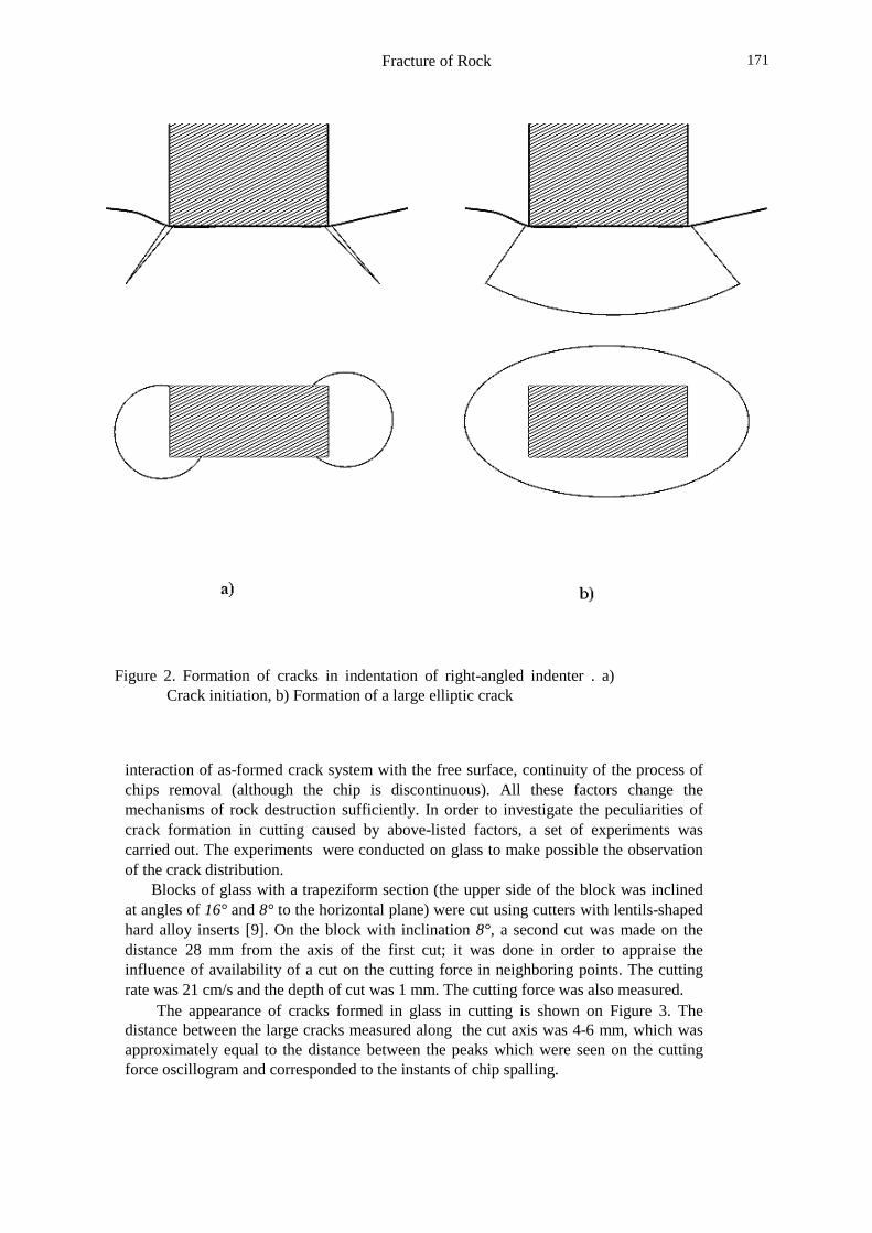
Figure la: Rock deformation and formation of crack system undervertical indentation. 1 -Hertzian cone crack2 -zone of confining pressure
large extent. Rock fragmentation proceeds most intensively when the hard brittle rock isloaded by a spherical indenter, the hard plastic rock by conical one or the weak rock bywedge-shaped one (for static loading) [6]. At small impact load, the conical impactormakes the maximal crater as compared with other shapes of indenters at the same load.At great impact load however, the most intensive fragmentation of rock is observedunder the loading by a cylindrical impactor [6].
In the indentation of spherical bit the cracks are initiated in the center of contactsurface and not on the contour of contact surface, as differentiated from the indentationof cylindrical bits [7]. The prismatic bits lead to a more intensive rock fragmentation forhard, viscous, non-cracked rocks, whereas the cylindrical ones are preferable forcracked, brittle, weak rocks [7].
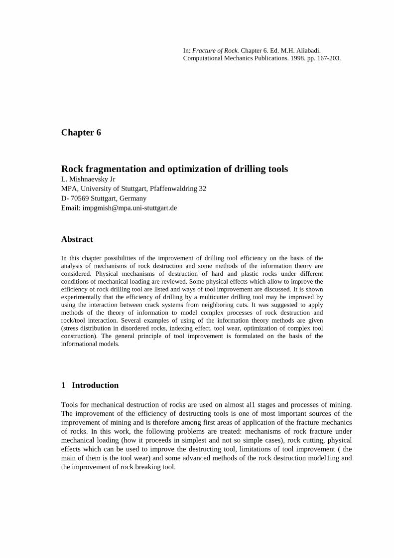
In pressing of the indenter with rectangular section into hard and plastic rocks, it wasobserved that. penny-shaped cracks are initiated in the vicinity of shorter side of thecontact surface, grow and then form a large elliptic crack, which can be considered ascorresponding to the cone crack in axisymmetric indentation [8]. The formation of thecracks in indentation of a rectangular indenter is shown on Figure 2.
Therefore, the destruction of rock under mechanical loading is a very complexprocess, which is caused by the interaction between. many levels of damage (localshears, growth of many macrocracks, spalling, etc) and is influenced by many

Fracture of Rock170
Figure 1b. Rock fragmentation under indenter . 3 -axial cracks.
/
factors, including random ones, like the composition of rock, the availability ofmicrodefects, etc. Variations of the shape of indenter, rock properties and otherparameters lead to drastic changes in the mechanism of rock destruction.
3 Cutting of Hard Rocks
A very important case of mechanical breakage of rocks by a tool is the rock cutting.Although the loss of energy due to the friction and wear in cutting is sufficiently morethan that in impact destruction of rocks, cutting is a very perspective method of rockremoval. It is determined by the fact that the cutting process goes continuously or almostcontinuously, rock is removed mainly due to the cutter movement., not. due to secondaryeffects like the crack interaction and the loss of energy due to dynamical effects (waveeffects, vibrations, etc) is sufficiently less than in impact destruction of materials. Themain disadvantage of cutting, i.e. fast wear and dulling of tool due to the continuoustool/rock interaction may be overcome in short time, in connection with the developmentof new wear-resistant and high strength materials, or using self-sharpening tools.
3.1 Mechanisms of Rock Cutting
Among the peculiarities of cutting as differentiated from the indentation, one canmention non-vertical direction of loading, non-axisymmetric shape of tool,
Fracture of Rock 171
Figure 2. Formation of cracks in indentation of right-angled indenter . a)Crack initiation, b) Formation of a large elliptic crack
interaction of as-formed crack system with the free surface, continuity of the process ofchips removal (although the chip is discontinuous). All these factors change themechanisms of rock destruction sufficiently. In order to investigate the peculiarities ofcrack formation in cutting caused by above-listed factors, a set of experiments wascarried out. The experiments were conducted on glass to make possible the observationof the crack distribution.
Blocks of glass with a trapeziform section (the upper side of the block was inclinedat angles of 16° and 8° to the horizontal plane) were cut using cutters with lentils-shapedhard alloy inserts [9]. On the block with inclination 8°, a second cut was made on thedistance 28 mm from the axis of the first cut; it was done in order to appraise theinfluence of availability of a cut on the cutting force in neighboring points. The cuttingrate was 21 cm/s and the depth of cut was 1 mm. The cutting force was also measured.
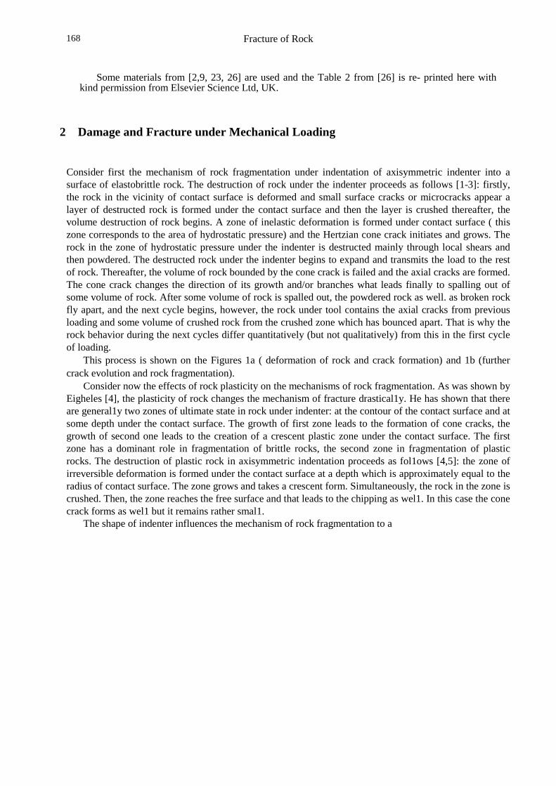
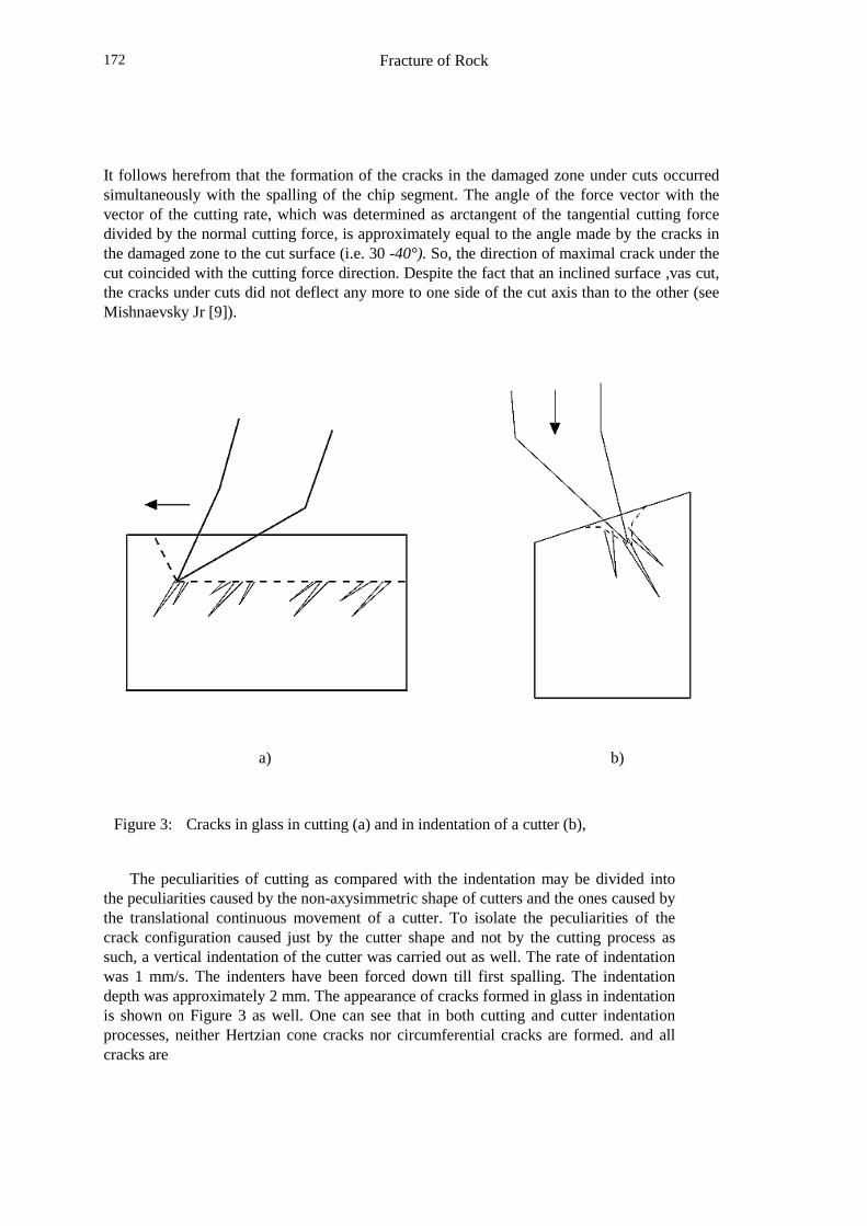
The appearance of cracks formed in glass in cutting is shown on Figure 3. Thedistance between the large cracks measured along the cut axis was 4-6 mm, which wasapproximately equal to the distance between the peaks which were seen on the cuttingforce oscillogram and corresponded to the instants of chip spalling.
Fracture of Rock172
It follows herefrom that the formation of the cracks in the damaged zone under cuts occurredsimultaneously with the spalling of the chip segment. The angle of the force vector with thevector of the cutting rate, which was determined as arctangent of the tangential cutting forcedivided by the normal cutting force, is approximately equal to the angle made by the cracks inthe damaged zone to the cut surface (i.e. 30 -40°). So, the direction of maximal crack under thecut coincided with the cutting force direction. Despite the fact that an inclined surface ,vas cut,the cracks under cuts did not deflect any more to one side of the cut axis than to the other (seeMishnaevsky Jr [9]).
a) b)
Figure 3: Cracks in glass in cutting (a) and in indentation of a cutter (b),
The peculiarities of cutting as compared with the indentation may be divided intothe peculiarities caused by the non-axysimmetric shape of cutters and the ones caused bythe translational continuous movement of a cutter. To isolate the peculiarities of thecrack configuration caused just by the cutter shape and not by the cutting process assuch, a vertical indentation of the cutter was carried out as well. The rate of indentationwas 1 mm/s. The indenters have been forced down till first spalling. The indentationdepth was approximately 2 mm. The appearance of cracks formed in glass in indentationis shown on Figure 3 as well. One can see that in both cutting and cutter indentationprocesses, neither Hertzian cone cracks nor circumferential cracks are formed. and allcracks are
Fracture of Rock 173
penny-shaped ones.Therefore, one can conclude that a zone containing penny-shaped cracks (damaged
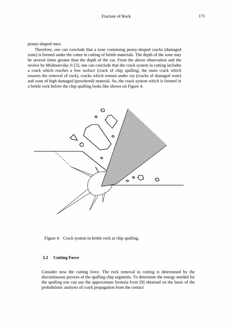
zone) is formed under the cutter in cutting of brittle materials. The depth of the zone maybe several times greater than the depth of the cut. From the above observation and thereview by Mishnaevsky Jr [2], one can conclude that the crack system in cutting includesa crack which reaches a free surface (crack of chip spalling; the main crack whichensures the removal of rock), cracks which remain under cut (cracks of damaged zone)and zone of high damaged (powdered) material. So, the crack system which is formed ina brittle rock before the chip spalling looks like shown on Figure 4.
Figure 4. Crack system in brittle rock at chip spalling.
3.2 Cutting Force
Consider now the cutting force. The rock removal in cutting is determined by thediscontinuous process of the spalling chip segments. To determine the energy needed forthe spalling one can use the approximate formula from [9] obtained on the basis of theprobabilistic analysis of crack propagation from the contact
Fracture of Rock174
point to the free surface:
A=16.7 Ga2/Kbr (1)
where a - depth of cutting, Kbr is the brittleness coefficient of rock (which wasintroduced by Rzhevsky & Novik [10] as a characteristic of plastic/brittle properties ofrock, and is defined as the ratio between the energy of the formation of new surface andthe overall deformation energy in mechanical loading of rock) and G is the specificsurface energy of rock. The mean cutting force Pc can be determined as the cuttingenergy (which is a sum of the chip spalling energy A and the frictional energy over thedistance equal to the spalling step) divided by the corresponding distance (spalling stepls -the distance between the two consecutive points in which the chip elements arespalled), which is calculated by the formula [1, 9]:
ls = 8.2 (G/gcr B Kbr)1/2
where gcr is the specific energy of crushing the rock, and B is the cut width. Thefrictional component of force can be found on the basis of following reasoning.Sulakshin [11] has shown that in cutting of brittle rocks, a layer of finely crushedmaterial is formed under the clearance face. This powdered brittle material plays therole of a lubricant between the cutter and rock. So, one can use the model of elasticfriction (i.e. the friction force is supposed to be proportional to the vertical componentof loading force). From the equations (1) and (2), one deduces the following formulasfor the components of cutting force:
Pz=2a [gcr GB/ Kbr (cos � � � � � � 1/2
(3)
Py = 2a (gcr GB/ Kbr � � � 1/2 (4)��� ��� �� ���������� ������� � �!� "$#%��"� ��&�����'� �#$�)( ����#�*+� -,� .�/� � �#0�/�' 213� �� �� �)� "$#%"'�3�4�� 5��6�757%����89��"����� and the horizontal surface.
3.3 Interaction between Crack Systems from Neighboring Cutters
As shown in [1, 9] the volume of detached rock under indentation of several indenterscan be increased by the using of the interaction of crack systems from neighboringindenters without an increase in loading energy (see Section 4.2). This effect isdetermined by the fact that two large cracks, the distance between which is of the sameorder as their size, can join together due to the interaction of their stress fields [1,8].
The large cracks are formed under cuts as well. It is reasonable to assume thatduring the cutting process, the barrier between cuts can be also spalled owing
~
Fracture of Rock 175
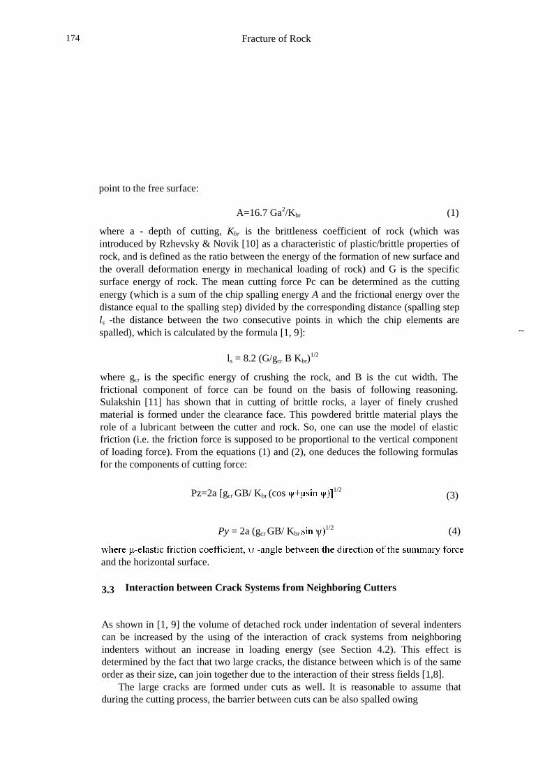
to the interaction between neighboring systems of cracks. It means that there is apossibility to increase the removing capacity of multicutter tool by using the interactionbetween the damaged zones. Taking into account the appearance of crack systems in thecutting process (see Figures 3,4), it is possible to present the process of barrier spalling,as shown in Figures 5a and 5b. The condition of barrier spalling can be formulated asfollows: the barrier between neighboring cuts is spalled due to the interaction betweencracks provided that the largest cracks under neighboring cuts are very close one toanother or even touch. If the cracks are penny-shaped and each of them is symmetricabout the axis of corresponding cut, the condition of barrier spalling can be stated also inthe following way: the barrier is spalled, if the distance between the axes of neighboringcuts is no more than the linear size of maximal cracks under cuts (i.e., the depth ofdamaged zone, approximately) .
Figure 5a: Spalling of barrier between cuts. Crack interaction.

Fracture of Rock176
Figure 5b: Spalling of barrier between cuts. Removed volume of rock.
This condition may be written as follows:
Bc < h- KsB (5)
where Bc is the barrier width (or the distance between cuts), h -linear size of the crackformed under the cutter (this value can be calculated by formulas from [1,9]), B -cutterwidth, Ks is the coefficient of the cutter shape. The coefficient Ks characterizes aprobability of initiation of a crack in different points through the cutter width. Thiscoefficient can be determined in the following way: when stress concentrators arelocated close to the side faces of cutter (i.e. the cutter is rectangular in face section), thecracks are nucleated rather near the side faces of the cutter, and this coefficient Ks can betaken to be zero. When the stress concentrators of cutter are located on the cut axis (i.e.the cutter is triangular in face section), the cracks are nucleated rather near the cut axisand Ks is equal to 1.
To verify the formula (5), the following experiments were performed. Marble
Fracture of Rock 177
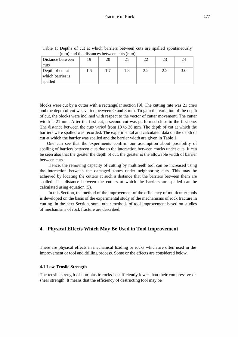
Table 1: Depths of cut at which barriers between cuts are spalled spontaneously(mm) and the distances between cuts (mm)
Distance betweencuts
19 20 21 22 23 24
Depth of cut atwhich barrier isspalled
1.6 1.7 1.8 2.2 2.2 3.0
blocks were cut by a cutter with a rectangular section [9]. The cutting rate was 21 cm/sand the depth of cut was varied between O and 3 mm. To gain the variation of the depthof cut, the blocks were inclined with respect to the vector of cutter movement. The cutterwidth is 21 mm. After the first cut, a second cut was performed close to the first one.The distance between the cuts varied from 18 to 26 mm. The depth of cut at which thebarriers were spalled was recorded. The experimental and calculated data on the depth ofcut at which the barrier was spalled and the barrier width are given in Table 1.
One can see that the experiments confirm our assumption about possibility ofspalling of barriers between cuts due to the interaction between cracks under cuts. It canbe seen also that the greater the depth of cut, the greater is the allowable width of barrierbetween cuts.
Hence, the removing capacity of cutting by multiteeth tool can be increased usingthe interaction between the damaged zones under neighboring cuts. This may beachieved by locating the cutters at such a distance that the barriers between them arespalled. The distance between the cutters at which the barriers are spalled can becalculated using equation (5).
In this Section, the method of the improvement of the efficiency of multicutter toolsis developed on the basis of the experimental study of the mechanisms of rock fracture incutting. In the next Section, some other methods of tool improvement based on studiesof mechanisms of rock fracture are described.
4. Physical Effects Which May Be Used in Tool Improvement
There are physical effects in mechanical loading or rocks which are often used in theimprovement or tool and drilling process. Some or the effects are considered below.
4.1 Low Tensile Strength
The tensile strength of non-plastic rocks is sufficiently lower than their compressive orshear strength. It means that the efficiency of destructing tool may be
Fracture of Rock178
increased if the tool is constructed or oriented in such a way, that large zones of hightensile stress are formed in rock.
The larger the zones of high tensile stresses as compared with the compression andshear zones, the more intensive and less energy consuming is the rock destruction (seeArtsimovich[13], Moscalev et al [15]). This rule gives a number of possibilities of theimprovement of constructions of drilling tools on the basis of a simple elastic simulationof stress distribution in rocks: actually, on the basis of numerically obtained stressdistributions in loaded rock one can say how intensive the rock will be destructed, andwhich improvements of the tool construction would be desirable.
The effect of low tensile strength of rock promotes the rock fragmentation in impactdrilling as well: under dynamical loading, the degree of brittleness of rocks increases, andtherefore the sensitivity of plastic rock to tensile stresses increases as well. Practically, itmeans that one may intensify the fragmentation of non-brittle rock by imposing theimpact load on the cutting force, which causes the embrittlement of the rock. It wasshown by Artsimovich et al [12] that the superimposing the impact component on thecutting force leads to the formation of larger cracks under cuts, than at a simple cutting.
4.1. Crack System Interaction and Indexing Effect
The volume of removed rock at the same energy of loading may be increased if thedestructing elements are located on the tool in such a way that the crack systems fromneighboring elements interact. As applied to cutting, this effect was investigated in theSection 3. Consider the effect of crack joining here in wider sense.
The joining together of cone cracks from neighboring indenters was observed byArtsimovich [8, 13] in indentation in glass and marble specimens. In so doing, thevolume of spalled rock from the joined crack systems was sufficiently greater than thesum of two independently spalled volumes from single indenters, The volume of rockspalled by two indenters was maximal when the distance between the indentation pointswas approximately 3.5-4 diameters of the indenters; the spalled volume was 1.3-1.4 (formarble) and 1.5-1.7 (for glass) times larger than the volume of rock removed by oneindenter multiplied by the amount of indenters. In these experiments, the indentationforces were not changed; the increase in the volume of removed rock was achieved onlythrough appropriate arrangement of indenters. Therefore, this effect can be very useful inoptimization of constructions of multiteeth tools: the reduction of energy per unit volumeof removed rock can be achieved by only optimal arrangement of destructing elements ona drilling tool, without any additional input of energy. The optimal arrangement of thedestructing elements means here such distance between them, that the cracks fromneighboring elements can join together. The spalling of
Fracture of Rock 179
large volumes of rock due to the joining of cracks from neighboring cuts withoutadditional energy can be also ensured if radial (facing) and tangential cutters are locatedon the same tool: in this case, the as-formed cracks are directed along perpendicularplanes, and they can simply join together .
Sometimes, the effect of interaction of crack systems is confused with the indexingeffect ( these effects are observed usually together and are difficult to separate). Theindexing effect implies that if two indenters or cutters deform rocks one near another andtheir stress fields are superimposed, it leads to more intensive microcracking in rocks.This effect can be observed separately from the crack interaction on I y at initial stagesof deformation of weakly damaged rocks. Mavlyutov [14] has studied the effect ofseveral rectangular indenters on the energy consumption in rock fragmentation. He hasshown that the energy consumption at simultaneous indentation of several indenters islower than in successive indentation. In so doing, this effect becomes weaker withincreasing of the amount of indenters. It was shown also that such an orientation of tworectangular indenters at which their shorter sides are parallel to the line between themensures lower energy consumption in indentation than in the case, when their longersides are parallel to the line between the indenters.
The indexing effect is studied theoretically in the Section 5.2.
4.3. Effect or Free Surfaces
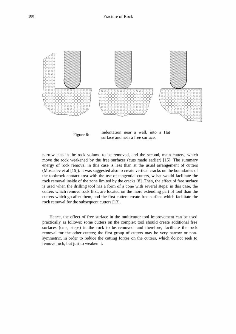
One of very important effects in mechanical fragmentation of rocks is the effect of freesurfaces available near the loaded volume. The specific energy of rock fragmentation invertical indentation (which can be defined as the energy to spalling divided by thespalled volume of rock) near a vertical free surface (see Fig. 6c) can be less than theenergy in simple indentation by a factor 30 to 100 [13]. Reversely, the specific energy ofrock fragmentation in vertical indentation near a wall (see Fig. 6a) can be 20-50 timesgreater than the energy of simple indentation. For example, in indentation in marble, theratios between the spal1ing forces near the wall Pl, in simple indentation P2 and near thefree surface P3 (see Figure 6) are as fol1ows [13]:
P1/P2=0.55; P3/P2=1.53 (6)
(the distances both between the wall and indentation point, and the free surface andindentation point were 6 mm in these experiments). The availability of free surfaces inthe vicinity of a loaded volume reduces the degree of triaxiality of stressed state and thevolume of crushed rock under the indenter w hat makes easier the removal of rock.
In order to use this effect in the real conditions- of multicutter drilling, a tool withtwo groups of cutters can be produced: first, leading cutters, which make
Fracture of Rock180
Figure 6: Indentation near a wall, into a Hatsurface and near a free surface.
narrow cuts in the rock volume to be removed, and the second, main cutters, whichmove the rock weakened by the free surfaces (cuts made earlier) [15]. The summaryenergy of rock removal in this case is less than at the usual arrangement of cutters(Moscalev et al [15]). It was suggested also to create vertical cracks on the boundaries ofthe tool/rock contact area with the use of tangential cutters, w hat would facilitate therock removal inside of the zone limited by the cracks [8]. Then, the effect of free surfaceis used when the drilling tool has a form of a cone with several steps: in this case, thecutters which remove rock first, are located on the more extending part of tool than thecutters which go after them, and the first cutters create free surface which facilitate therock removal for the subsequent cutters [13].
Hence, the effect of free surface in the multicutter tool improvement can be usedpractically as follows: some cutters on the complex tool should create additional freesurfaces (cuts, steps) in the rock to be removed, and therefore, facilitate the rockremoval for the other cutters; the first group of cutters may be very narrow or non-symmetric, in order to reduce the cutting forces on the cutters, which do not seek toremove rock, but just to weaken it.
Fracture of Rock 181
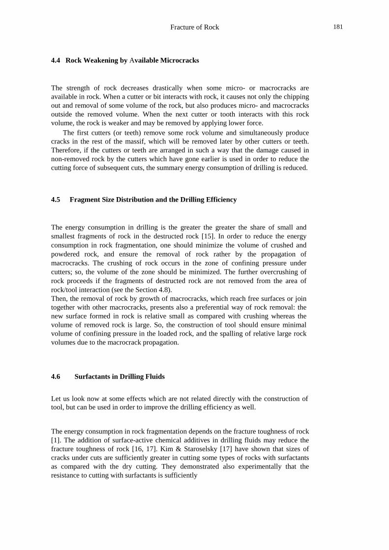
4.4 Rock Weakening by Available Microcracks
The strength of rock decreases drastically when some micro- or macrocracks areavailable in rock. When a cutter or bit interacts with rock, it causes not only the chippingout and removal of some volume of the rock, but also produces micro- and macrocracksoutside the removed volume. When the next cutter or tooth interacts with this rockvolume, the rock is weaker and may be removed by applying lower force.
The first cutters (or teeth) remove some rock volume and simultaneously producecracks in the rest of the massif, which will be removed later by other cutters or teeth.Therefore, if the cutters or teeth are arranged in such a way that the damage caused innon-removed rock by the cutters which have gone earlier is used in order to reduce thecutting force of subsequent cuts, the summary energy consumption of drilling is reduced.
4.5 Fragment Size Distribution and the Drilling Efficiency
The energy consumption in drilling is the greater the greater the share of small andsmallest fragments of rock in the destructed rock [15]. In order to reduce the energyconsumption in rock fragmentation, one should minimize the volume of crushed andpowdered rock, and ensure the removal of rock rather by the propagation ofmacrocracks. The crushing of rock occurs in the zone of confining pressure undercutters; so, the volume of the zone should be minimized. The further overcrushing ofrock proceeds if the fragments of destructed rock are not removed from the area ofrock/tool interaction (see the Section 4.8).Then, the removal of rock by growth of macrocracks, which reach free surfaces or jointogether with other macrocracks, presents also a preferential way of rock removal: thenew surface formed in rock is relative small as compared with crushing whereas thevolume of removed rock is large. So, the construction of tool should ensure minimalvolume of confining pressure in the loaded rock, and the spalling of relative large rockvolumes due to the macrocrack propagation.
4.6 Surfactants in Drilling Fluids
Let us look now at some effects which are not related directly with the construction oftool, but can be used in order to improve the drilling efficiency as well.
The energy consumption in rock fragmentation depends on the fracture toughness of rock[1]. The addition of surface-active chemical additives in drilling fluids may reduce thefracture toughness of rock [16, 17]. Kim & Staroselsky [17] have shown that sizes ofcracks under cuts are sufficiently greater in cutting some types of rocks with surfactantsas compared with the dry cutting. They demonstrated also experimentally that theresistance to cutting with surfactants is sufficiently
Fracture of Rock182
(45% -55%) lower than that in dry cutting. Therefore, the addition of surface-activeadditives to drilling fluids may intensify the rock fragmentation in drilling.
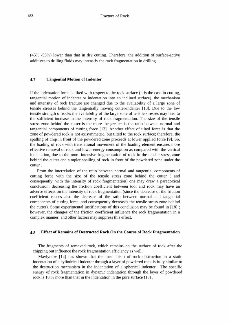
4.7 Tangential Motion of Indenter
If the indentation force is tilted with respect to the rock surface (it is the case in cutting,tangential motion of indenter or indentation into an inclined surface), the mechanismand intensity of rock fracture are changed due to the availability of a large zone oftensile stresses behind the tangentially moving cutter/indenter [13]. Due to the lowtensile strength of rocks the availability of the large zone of tensile stresses may lead tothe sufficient increase in the intensity of rock fragmentation. The size of the tensilestress zone behind the cutter is the more the greater is the ratio between normal andtangential components of cutting force [13] .Another effect of tilted force is that thezone of powdered rock is not axisymmetric, but tilted to the rock surface; therefore, thespalling of chip in front of the powdered zone proceeds at lower applied force [9]. So,the loading of rock with translational movement of the loading element ensures moreeffective removal of rock and lower energy consumption as compared with the verticalindentation, due to the more intensive fragmentation of rock in the tensile stress zonebehind the cutter and simpler spalling of rock in front of the powdered zone under thecutter .
From the interrelation of the ratio between normal and tangential components ofcutting force with the size of the tensile stress zone behind the cutter ( andconsequently, with the intensity of rock fragmentation) one may draw a paradoxicalconclusion: decreasing the friction coefficient between tool and rock may have anadverse effects on the intensity of rock fragmentation (since the decrease of the frictioncoefficient causes also the decrease of the ratio between normal and tangentialcomponents of cutting force, and consequently decreases the tensile stress zone behindthe cutter). Some experimental justifications of this conclusion may be found in [18] ;however, the changes of the friction coefficient influence the rock fragmentation in acomplex manner, and other factors may suppress this effect.
4.8 Effect of Remains of Destructed Rock On the Course of Rock Fragmentation
The fragments of removed rock, which remains on the surface of rock after thechipping out influence the rock fragmentation efficiency as well.
Mavlyutov [14] has shown that the mechanism of rock destruction in a staticindentation of a cylindrical indenter through a layer of powdered rock is fully similar tothe destruction mechanism in the indentation of a spherical indenter . The specificenergy of rock fragmentation in dynamic indentation through the layer of powderedrock is 18 % more than that in the indentation in the pure surface f181.
Fracture of Rock 183
The accumulation of fragments of destructed rock in front of the cutter face leads tothe overcrushing of rock, and to additional losses of the energy. This can be avoided byusing of the cutters with one-sided bevel on the cutter face [15].
So, the rapid removal of remains of destructed rock from the area of rock/toolinteraction (by the means of constructive modifications of the tool, or by other means,like drilling fluids) is a very important for the efficiency of drilling .
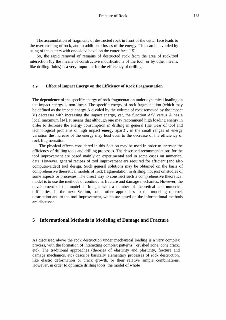
4.9 Effect of Impact Energy on the Efficiency of Rock Fragmentation
The dependence of the specific energy of rock fragmentation under dynamical loading onthe impact energy is non-linear. The specific energy of rock fragmentation (which maybe defined as the impact energy A divided by the volume of rock removed by the impactV) decreases with increasing the impact energy, yet, the function A/V versus A has alocal maximum [14]. It means that although one may recommend high loading energy inorder to decrease the energy consumption in drilling in general (the wear of tool andtechnological problems of high impact energy apart) , in the small ranges of energyvariation the increase of the energy may lead even to the decrease of the efficiency ofrock fragmentation.
The physical effects considered in this Section may be used in order to increase theefficiency of drilling tools and drilling processes. The described recommendations for thetool improvement are based mainly on experimental and in some cases on numericaldata. However, general recipes of tool improvement are required for efficient (and alsocomputer-aided) tool design. Such general solutions may be obtained on the basis ofcomprehensive theoretical models of rock fragmentation in drilling, not just on studies ofsome aspects or processes. The direct way to construct such a comprehensive theoreticalmodel is to use the methods of continuum, fracture and damage mechanics. However, thedevelopment of the model is fraught with a number of theoretical and numericaldifficulties. In the next Section, some other approaches to the modeling of rockdestruction and to the tool improvement, which are based on the informational methodsare discussed.
5 Informational Methods in Modeling of Damage and Fracture
As discussed above the rock destruction under mechanical loading is a very complexprocess, with the formation of interacting complex patterns ( crushed zone, cone crack,etc). The traditional approaches (theories of elasticity and plasticity, fracture anddamage mechanics, etc) describe basically elementary processes of rock destruction,like elastic deformation or crack growth, or their relative simple combinations.However, in order to optimize drilling tools, the model of whole
Fracture of Rock184
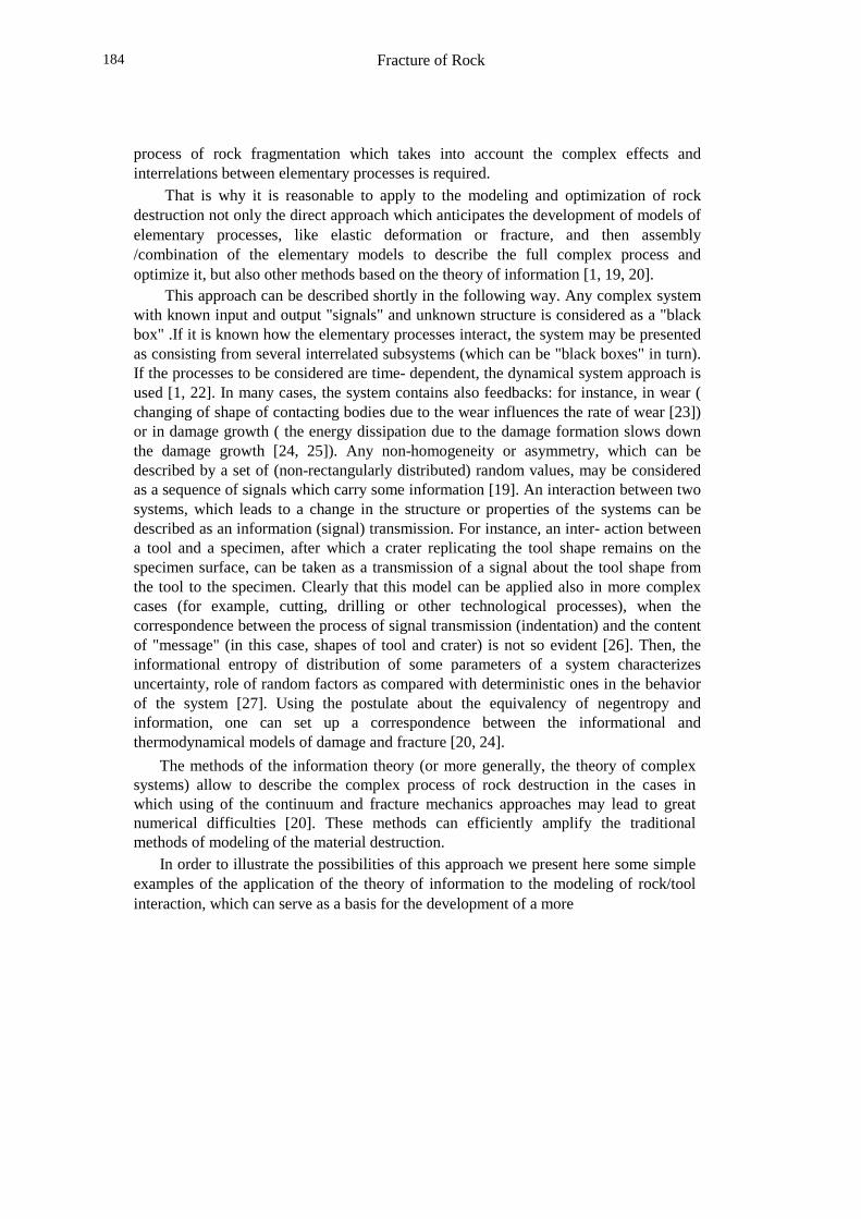
process of rock fragmentation which takes into account the complex effects andinterrelations between elementary processes is required.
That is why it is reasonable to apply to the modeling and optimization of rockdestruction not only the direct approach which anticipates the development of models ofelementary processes, like elastic deformation or fracture, and then assembly/combination of the elementary models to describe the full complex process andoptimize it, but also other methods based on the theory of information [1, 19, 20].
This approach can be described shortly in the following way. Any complex systemwith known input and output "signals" and unknown structure is considered as a "blackbox" .If it is known how the elementary processes interact, the system may be presentedas consisting from several interrelated subsystems (which can be "black boxes" in turn).If the processes to be considered are time- dependent, the dynamical system approach isused [1, 22]. In many cases, the system contains also feedbacks: for instance, in wear (changing of shape of contacting bodies due to the wear influences the rate of wear [23])or in damage growth ( the energy dissipation due to the damage formation slows downthe damage growth [24, 25]). Any non-homogeneity or asymmetry, which can bedescribed by a set of (non-rectangularly distributed) random values, may be consideredas a sequence of signals which carry some information [19]. An interaction between twosystems, which leads to a change in the structure or properties of the systems can bedescribed as an information (signal) transmission. For instance, an inter- action betweena tool and a specimen, after which a crater replicating the tool shape remains on thespecimen surface, can be taken as a transmission of a signal about the tool shape fromthe tool to the specimen. Clearly that this model can be applied also in more complexcases (for example, cutting, drilling or other technological processes), when thecorrespondence between the process of signal transmission (indentation) and the contentof "message" (in this case, shapes of tool and crater) is not so evident [26]. Then, theinformational entropy of distribution of some parameters of a system characterizesuncertainty, role of random factors as compared with deterministic ones in the behaviorof the system [27]. Using the postulate about the equivalency of negentropy andinformation, one can set up a correspondence between the informational andthermodynamical models of damage and fracture [20, 24].
The methods of the information theory (or more generally, the theory of complexsystems) allow to describe the complex process of rock destruction in the cases inwhich using of the continuum and fracture mechanics approaches may lead to greatnumerical difficulties [20]. These methods can efficiently amplify the traditionalmethods of modeling of the material destruction.
In order to illustrate the possibilities of this approach we present here some simpleexamples of the application of the theory of information to the modeling of rock/toolinteraction, which can serve as a basis for the development of a more
Fracture of Rock 185
general theory.
5.1 Informational Description of Tool Shape
The intensity of rock destruction in indentation is determined by the shape of indenters.Let us look at three simplest forms of indenters: spherical, conical and cylindrical ones.Although the shapes of indenters differ evidently and the peculiarities of destruction foreach of the indenters have been well investigated, there is no quantitative parameter("input" or apriopi characteristic) which can characterize the form, serve as a criterionfor their comparison and which may be generalized for more complex cases of rock/toolinteraction.
The experiments on the indentation of differently shaped indenters, described in [6],have shown that the volume of craters of spalled rock is maximal for conical, minimalfor spherical and medium for cylindrical indenters. If one compares the result with thecontact stress distributions for these cases [29], one can see that the maximal volume ofcrater corresponds to the most sharp curve of contact stress distribution, whereas theminimal volume corresponds to the most homogeneous contact stress distribution.
One can suppose that the "sharpness" (i.e. non-homogeneity) of contact stressdistribution is a parameter which determines the intensity of rock destruction (in thiscase, the volume of crater). To characterize this "sharpness" of distributionsquantitatively for arbitrary tool shape (including, for example, a non-axisymmetricdrilling bit with many teeth), one can use an informational entropy of contact stressdistribution [1, 26].
Let us suppose that a contact stress distribution function is given in followinggeneral form:
c= F(x, y, z) (7)
where c is the contact stress in a point, x, y, z -coordinates or a contact point. Thefunction (7) is determined by the tool shape and the stress-strain relationship for a givenrock. Peaks or this function correspond to stress concentrators on the tool surface.Quantifying the range or contact stress variation, one can obtain from eq. (7) theprobability distribution or contact stress over the contact surface:
p( c)=(1/NL : ; < = > x,y,z); c] (8)
where p ( c) is the probability that the contact stress in a point is equal to the value c, NL -the amount of quantisation levels of c, j -the number of a contact point, Y[] -stepfunction, Y[X1; X2] = 1, when Xl = X2 and is equal to 0, otherwise.
The informational entropy of contact stress distribution can be calculated by theformula:
Hc=-? @ p( c) ln p( c) d c (9)
Fracture of Rock186
The greater the parameter Hc, the more non-homogeneous the contact stressdistribution. This value characterizes the "sharpness" (non-homogeneity) of con- tactstress distribution for arbitrary function F, and thus, for arbitrary drilling bit shape. Thisparameter does not depend on any kind of symmetry of tool, and may be used for toolshapes of any complexity.
In order to investigate the influence of the parameter Hc on the intensity of rockdestruction, a series of contact stress distributions with different parameters Hc wastaken. Each of the distributions corresponds to some shape of indenter. The initialdamage parameter in rock for each value Hc was calculated.
The damage evolution in contact interaction proceeds as follows: first, the surfacedamage is formed in the vicinity of the contact surface, and then the damage densitybegins to grow. The damage growth rate is the more the greater the damage parameter[25, 29]; therefore, the initial damage (in this case, surface damage) determines thedamage in the rock at later stage of destruction. That is why we use here the surfacedamage as a characteristic of the damaged state of the rock.
The contact stress distribution (i.e. the function (7) ) can be presented as a powerfunction in a rather general case:
c (x) = q1 (x/ac) q2 (10)
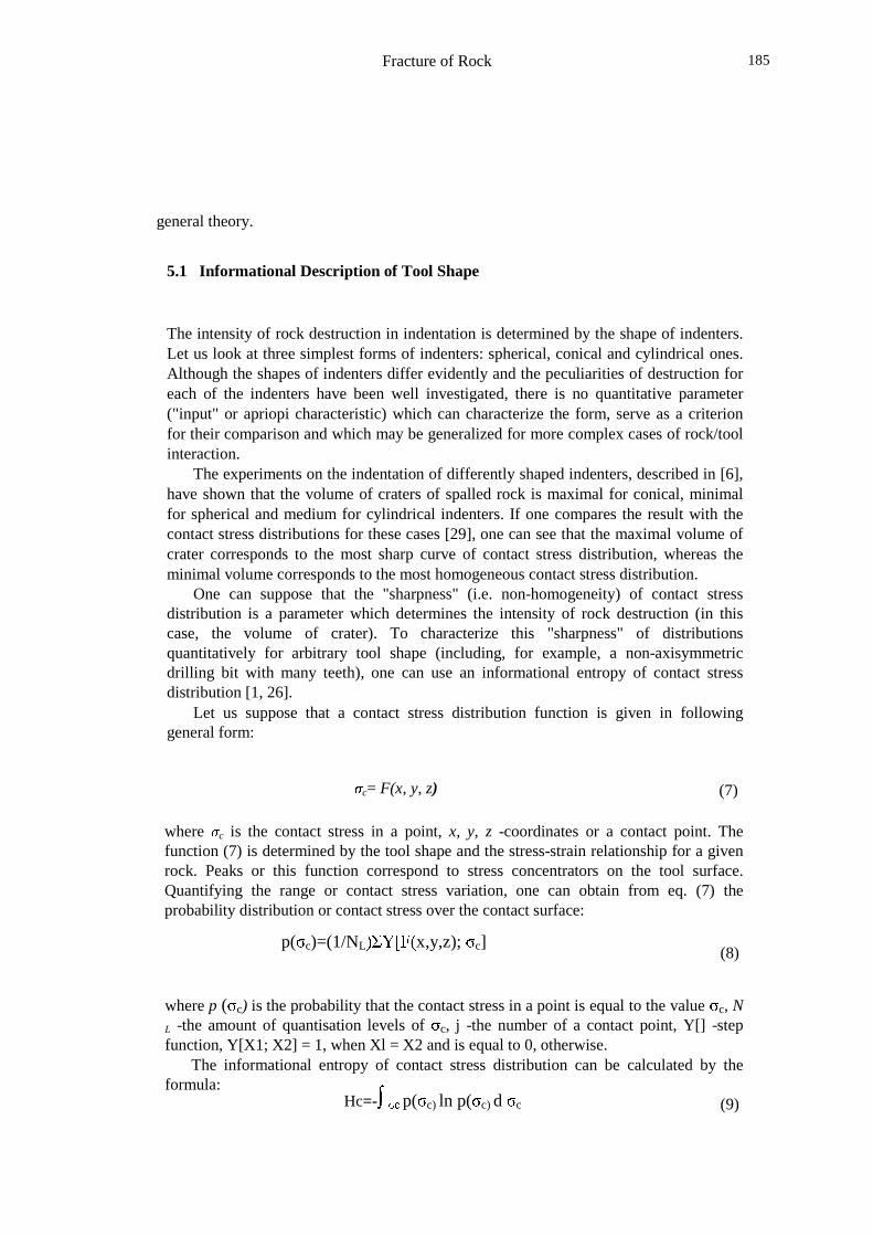
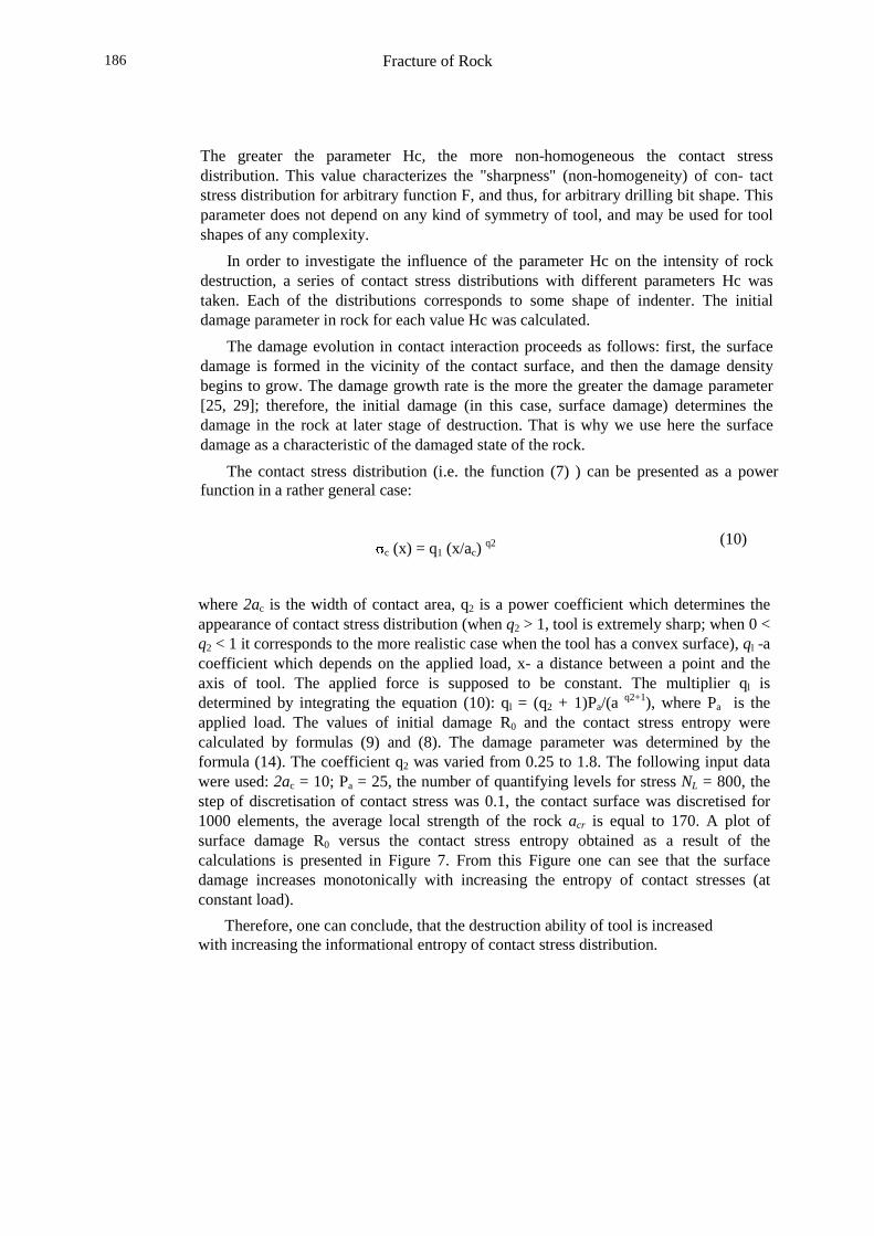
where 2ac is the width of contact area, q2 is a power coefficient which determines theappearance of contact stress distribution (when q2 > 1, tool is extremely sharp; when 0 <q2 < 1 it corresponds to the more realistic case when the tool has a convex surface), ql -acoefficient which depends on the applied load, x- a distance between a point and theaxis of tool. The applied force is supposed to be constant. The multiplier ql isdetermined by integrating the equation (10): ql = (q2 + 1)Pa/(a q2+1), where Pa is theapplied load. The values of initial damage R0 and the contact stress entropy werecalculated by formulas (9) and (8). The damage parameter was determined by theformula (14). The coefficient q2 was varied from 0.25 to 1.8. The following input datawere used: 2ac = 10; Pa = 25, the number of quantifying levels for stress NL = 800, thestep of discretisation of contact stress was 0.1, the contact surface was discretised for1000 elements, the average local strength of the rock acr is equal to 170. A plot ofsurface damage R0 versus the contact stress entropy obtained as a result of thecalculations is presented in Figure 7. From this Figure one can see that the surfacedamage increases monotonically with increasing the entropy of contact stresses (atconstant load).
Therefore, one can conclude, that the destruction ability of tool is increasedwith increasing the informational entropy of contact stress distribution.
Fracture of Rock 187
5.2
Figure 7: Surface damage in rock plotted versus the contact stressentropy [26].
Entropy Maximization and. Indexing Effect
The stress distribution in rocks depends on a number of random factors: spatialdistribution of minerals, distributions of the grain sizes, shapes, properties andorientations, superposition of stress field caused by each stress concentrators inmaterials, variability of properties and types of local behavior, cooperative effects, etc.These effects cause high variability of the local stresses from the values which arecalculated with the use of the averaged constants and elastic or plastic solutions.Lippmann [30] noted that the stress in disordered materials presents a sum of anaveraged stress and a microstress caused by the local microstructure and heterogeneities.This microstress can be considered as a local fluctuation of stress field. Themicrostructure of heterogeneous rock, distribution of minerals, their sizes andorientation are usually unknown. Mishnaevsky J r & Schmauder [25] have shown, that amaterial becomes more heterogeneous with increasing damage parameter andapproaching to failure. It leads also to the increase of stochastic component in the localstress in the materials.
So, the problem of description of stress state in disordered materials is a
Fracture of Rock188
problem of determination of parameters under conditions of the lack of requiredinformation. In order to solve such problems, one can use the maximum entropy method[21]. Consider the stress distribution in a loaded rock. A stress in a point is determinedby the interaction between stress fields of ail nearest stress concentrators (inclusions,hard particles, microcracks, pile-ups of dislocations). The stress distribution which isdetermined by the superposition of stress fields of a wealth of randomly distributedstress concentrators can be taken as random and may be described by a probabilityfunction, for instance, by a probability function of the von Mises equivalent stress (forsimplicity, we shall use here this scalar value, but this approach can be applied todescribe a distribution of vector components as well). In the case of homogeneous rock,this probability function is reduced to the Dirac delta function. For the case ofdisordered materials, this probability function is determined from the condition ofmaximal likelihood of a given stress state, which corresponds to a maximal entropy ofthe system. In order to determine the probability function which describes the stressstate, all available data about the stress distribution are introduced into thecorresponding Lagrangian, and the probability function is determined on the basis of thecondition of the maximum of this Lagrangian.
For example, consider the case when the rock is extremely heterogeneous andalmost no information, except for the energy of loading A and strained volume V isgiven. One should note here that this model may be applicable to thermic loading, butnot to mechanical loading at which conditions and direction of loading are knownalways; the other case in which the model can be applied is that when there is two levelsprocess (for example, micro- and macrofracture) in a problem to be considered and onemay neglect geometrical effects on one of the levels.
The restriction on possible probability distributions of stress is minimal andinvolves only a prescribed average specific elastic energy ae: A�B a(ae) ae = A/V wherepa(ae) -probability function of the specific elastic energy, A -energy of loading, V -strained volume. (This equation is written for the distribution of specific elastic energyae = kp
2, and not stress for the sake of simplicity; here kp CED$F)G H&I4J�KML N von MisesO�P�QSR T$UWV O X�Y9Z&Y\[�O�Z]Z_^3`badc�e�Q�X�fhg%e�i�Q3V QSZ_^ a�jkeSR/Z�Z�e�X�lmZd[�U�Y�R e'npoSqbr�Ots�e$X�iSR Y)R e'Xue�vwg%U�xSR g%Q'gentropy is written in such a way:
y za(ae) ln pa(ae) -> max, (11)
The Langangian of the system looks as follows [21]:
{ |1 } ~ � � a(ae� � � 2 [A/V- � � a(ae) ae ] –
�3 � a(ae) ln pa(ae), (12)
� � � � �1 � 2 � 3- coefficients. Minimizing the Lagrangian (dZ/ pa(ae) = 0), one
Fracture of Rock 189
can obtain:p( � � 1 � � � p)
1/2 exp(-0.5 kp 1 2) (13)
���'�����1� 2� 3= V/A, p( ) -probability function of von Mises equivalent stress.
If one states the condition of local failure (the critical level of equivalent stress, forinstance), one can determine the probability of microcrack formation (i.e., damageparameter) as well:
R=� c p( ��� � exp(-kp 1 2
cr)
(14)
where cr -critical level of the equivalent stress. This formula relates the micro- crackdensity and the probability function of stress distribution (which depends on theheterogeneity of rock). One should note here that the value cr in such a medium shouldbe a random value; therefore, the formula (14) can be used only as a roughapproximation (the value cr means therefore an averaged critical level of the equivalentstress over the loaded volume).
One can introduce into the Lagrangian (12) also other boundary conditions than thesimplest ones used above, what may allow us to take into account the structure of thematerial and the strain compatibility. For example, one can exert into the Lagrangian thecorrelation function of stress in different points of strained volume ( that can beconsidered as an analogue of strain compatibility equations as applied to the brittledisordered materials), or the average deviation of stress in strained volume points fromthe stress being calculated by an elastic problem solution (with averaged elasticconstants).
Thus, the developed method makes it possible to obtain the probabilistic descriptionof stress distribution and damage in disordered material, taking into account the lack ofinformation about the material structure and the available (insufficient) information aboutit.
Practically, it means that the problem of stress state modeling is solved from the"other end": usually, one supposes that an ideally elastic material (or a material withother fully known properties) is considered, and then one begins to introduce corrections,which should allow for heterogeneity and other deviations of the material from the idealcase; here, we accept initially, that the information about the material structure andbehavior is lacking, and then begin to introduce any available information into theLagrangian.
In order to illustrate possibilities of practical using of developed model, consider theinfluence of superposition of stress fields and the effect of indexing on the damage inrock.
Consider simultaneous and successive loadings of a rock by several (in this case,two) indenters. In first case (i.e. the simultaneous indentation), there are the superpositionof stress fields from the indenters (it is supposed that the
Fracture of Rock190
indentations are made on rather small distance, which is about 1... 10 indenter radii). Inthe second case (the successive loading), the rock is unloaded during the time intervalbetween indentations and the stress fields do not interact ( the influence of as-formeddamage on the formation of new damage is neglected).�b���t�\ ��¢¡&£�¤�¥ �)¦ §$¤©¨�ª «h¡�§�¬®_¦ ¤'¯+° �±¦�¤$²���¤$�/³���¦�§�¤©´$�¢²'��¤$§��/� ²©´�µ¶¨
0· ¸p¹ º¼»�½¿¾$À�Á%À�Â$½parameter corresponding to the single loading is designated by R0. Consider the valuesof damage R for simultaneous and successive loading by two equal loads. In line withthe damage accumulation hypothesis, one can write for the case of successive loading:Rsuc = 2 R0. In the simultaneous loading (when the stress fields are superimposed), thedamage is equal to the sum of damage parameters from each indenter plus some valueßR which is determined by stress field superposition: Rsim = 2 R0 + ÃÅÄwÆÈÇÊÉÌË Í)ÎÅÏ%Ð�Ñ�ÒSË�Ò�Ó+Ôthe value Õ¼Ö¶×/ØÚÙÜÛ�Ý&Þ�ß�Ù.ß+×/à\× á/âãÞ'äwà Þ�å Ù�àæä�Ù'×/à ç$Ý�èêép×/ë èWë'á4ì$èêíî× å�Ý�Þ�å Ý�Ù�å�ïîä�Þ$Ý�í%Ù�á)×�Þ�ð$ñMò'ç�èêá/Þóá/ì�èstress fields superposition in a point in which the rock does not fail at the successiveloading. This probability can be determined as a probability of coincidence of twoô�õ$ô�ö�÷!ø_ùûú�öÜô�õ$ô�ö�÷küý÷/þ�ú ÷ ÿ
cr in the point at successive loading, and an event B that 0"> O"cr in the same point at simultaneous loading: ����� ProbA ProbB, where ProbA,B isthe probability of the event A or B. Determine the value ProbA and ProbB. It is clear thatProbA = 1- Rsuc and ProbB is equal to the probability function psim� ������ ��������������� ���� ���� �� ���for simultaneously applied loads integrated over stresses from critical stress to theinfinity. Then, the distribution of stress for the case of superimposed fields can be foundas a convolution of two distributions p0� �! #"%$'&�(�)+*),$�- (�)#.�/10,&),$2$3- 0�- ),(45&$6- (*�),7�- (�89/#.'/ratio between the damage in rock in simultaneous and successive loading by the same: ;�<,= >
Rsim/ Rsuc, one can calculate this value with the use of eq. (14) as fol1ows:
?A@CBED�FHGJI KML psimN O�P
Substituting eq. (14) to eq. (15), one can obtain: ProbB QSRUTWV 1 acr) R0. After samerearrangements, one derives:
X Y Z [ \ ] ^ Y _ ` a0)(1-ln R0)
Let us take R0 = 0.3 (i.e. the cracked part of loaded volume of rock is considered thevalue 0.3 presents the critical damage density at which a large crack is formed [29]).b�c�dfe�gihjdkc�l,mdkn2oUp�qrd,sut vxwiy3z|{ }Awit ~~ut
To verify this result, one can use the experimental data from [31]. In this work, themaximal distances between indenters which ensures the spalling of barriers betweencraters in successive and simultaneous indentations of two and three indenters in marbleblocks were determined. It was shown that this distance for simultaneous indentation oftwo indenters is equal approximately to 8 radii of indenters and for the case of thesuccessive indentation presents 6 radii. So,
Fracture of Rock 191
the simultaneity of indentations leads to the increase by 33% in the linear size of as-formed cracks. The area of new surface may be taken as being proportional to thedamage parameter to the power 2.42 [25]. So, the linear size of as-formed cracks should� ���,�2���#�����f��������,����,������������������� �1��� ���,����� ��������� �����,����f�C������������������#���� 1.21, in�, , ,¡¢�£��,¤ ,¥§¦©¨ ª�«¬ª�«�¥§¢U¥#®�¥,¤�ª'¯1¡�£�¥±°�²±³%´J¦j¥§µu®%¥©ª�«¥§¶�#° µ�¥ ·�¸f² ¹�¹�º�¨ ª' ,¡¢U¢�¥�®%�¡�¤�£�®�ª�¡¬ª�«�¥increase by 1.55 in the linear crack size. The deviation is about 16 %. One can see thatthe developed model gives the results which are rather close to the experimental datadespite the rough assumptions used in the model.
So, the intensity of rock destruction increases sufficiently (almost 1.5 times) insimultaneous indentation of several indenters as comparing with the successiveindentation of the same indenters. Therefore, one may conclude that the arrangement ofcutters or teeth in pairs or in groups, which ensures the superposition of stress fieldsfrom neighboring elements, can present a way to improve the efficiency of drilling bycomplex tools in brittle rocks. This is confirmed by the results of Moscalev et al [15],who have shown that the placement of cutters on a multicutter drill bit in groups ensureslower energy consumption and higher efficiency of rock fragmentation than the uniformarrangement of cutters.
5.3. Dynamical Systems with Feedbacks and their Application to Modelingof Tool Wear
From general reasonings one may suppose that the simplest way to construct a mostefficient destructing tool is to make it extremely sharp. However, any tool will change itsshape and lose its sharpness in short time due to the wear processes and the duration ofthis period is the shorter the sharper the tool is. Actually, wear is a main limitation indesign of breaking tool, and any concept of tool improvement which is based just on therock fracture studies and does not take into account the tool wear is incomplete.
Tool wear is determined by a number of mechanisms, including abrasive processes,fatigue, adhesion wear, fretting, oxidization, etc. However, Artsimovich [13] has shownthat the main mechanism of wear of tool from composite material in rock drilling is thefatigue failure of small areas on the contact surface (mainly, filler grains) intensivelystimulated by the local heating.
The tool from a particulate composite material (like hard alloys, for instance) whichis worn by the fatigue failure of filler grains on the contact surface is shown on theFigure 8. On the basis of the assumptions about the fatigue mechanism of drilling toolwear one may obtain the following formula for the rate of local wear [23]:
y=2.6 (NgT/Qf np 3/2 T0) exp [(Ea/kb)(1/T0»�¼�½�¾W¿�» 2
WC À 2c], (17)
Fracture of Rock192
Figure 8. Fatigue wear of composite tool
where y -the average thickness of worn layer over the contact surface of tool divided bythe friction (cutting) distance, Ng -the number of hard grains of the rock per unit length,T and T0 -temperature in the contact area and room temperature, Qf is the contact area,
WC is the strength of the carbide particle, np is the mean number of the particles per unitof contact area, c -contact stress, Ea is the activation energy, kb -Boltzmann constant.
After the removal of the particles from the tool surface, the tool shape is changed,the contact stress redistribution occurs and then the redistribution of wear rates overcontact surface comes about. That can be considered as a transient in a dynamicalsystem with feedback: the tool shape determines the distribution of wear rates over thecontact surface, and in turn this distribution influences the tool shape.
The wearing tool can be represented as the dynamical system in the form
Fracture of Rock 193
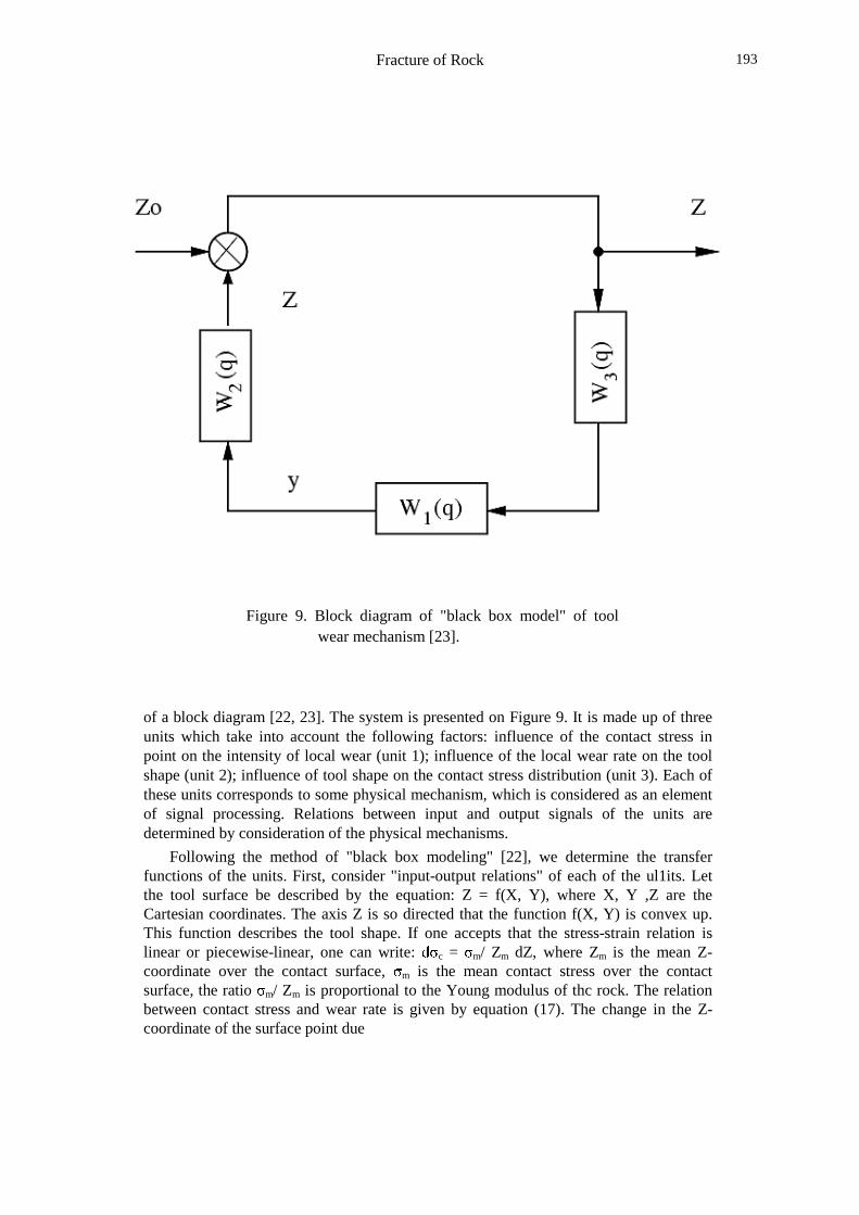
Figure 9. Block diagram of "black box model" of toolwear mechanism [23].
of a block diagram [22, 23]. The system is presented on Figure 9. It is made up of threeunits which take into account the following factors: influence of the contact stress inpoint on the intensity of local wear (unit 1); influence of the local wear rate on the toolshape (unit 2); influence of tool shape on the contact stress distribution (unit 3). Each ofthese units corresponds to some physical mechanism, which is considered as an elementof signal processing. Relations between input and output signals of the units aredetermined by consideration of the physical mechanisms.
Following the method of "black box modeling" [22], we determine the transferfunctions of the units. First, consider "input-output relations" of each of the ul1its. Letthe tool surface be described by the equation: Z = f(X, Y), where X, Y ,Z are theCartesian coordinates. The axis Z is so directed that the function f(X, Y) is convex up.This function describes the tool shape. If one accepts that the stress-strain relation islinear or piecewise-linear, one can write: Á c = m/ Zm dZ, where Zm is the mean Z-coordinate over the contact surface, m is the mean contact stress over the contactsurface, the ratio m/ Zm is proportional to the Young modulus of thc rock. The relationbetween contact stress and wear rate is given by equation (17). The change in the Z-coordinate of the surface point due
Fracture of Rock194
to the wear can be found as follows
Z(t) =Z0-vc Â�ÃÄ�Å
where Z0 is the Z-coordinate of the point in the initial moment of cutting, vc is thecutting rate. From equations (17)-(18) it is seen that unit 2 can be considered asintegrating, and unit 3 as proportional one. The unit 1 can be taken to be proportionalone only as a first approximation. In this case, its transfer function W(q) = L[y( c)]/L( c) becomes a constant value, which is equal to Cy = dy( c)/Æ c (i.e. theproportionality coefficient in a piecewise-linear approximation of the function ( 17)).Wehave:
W1(q)= L[y( c)]/ L( c) = Cy (19)
where L() -Laplace transform, Cy -a coefficient. The value Cy = dy/d c can be calculatedwith the use of the equation (17). Assuming that c Ç m, one obtains:
Cy È©É2Ê 2WC / T0
3c ) Ë�ÌÍ�ÎUÏ 2
WC Ð 2c) (20)
The transfer function of the unit 2 (integrating one) presents the Laplace transformof function Z(t), which is given by eq.(18): W2(q) = L[Z(t)] = vc/q. The transfer functionof the proportional unit 3 is equal to the proportionality coefficient between m and Zm:W3(q) = m/Zm. With the scheme of Figure 9 we can obtain the transfer function of allthe system, and, after some rearrangements, the formula describing the variations oftool shape during wear:
W(q) =1/(1+W1 W2 W3) = 1/(1+ Cy m vcq/ Zm)
and
Z(t) = Z0 exp(-2Cy m Z0vct/ Zm2) (22)
where W1, W2, W3are the transfer functions of the units 1, 2, 3 correspondingly, thefunction Z(t) = f(X, Y, Z0, t) characterizes the tool shape after a time t, Z(t) is Z-coordinate of a given point of the contact surface at instant t .The formula (22) isobtained from (21) as a reverse Laplace transform of the product of the transfer function(21) by the Laplace transform of the input signal (which is the initial form of the tool; Z= f(x, Y)).
From equation (22) it follows that the greater the initial height of a point of the toolsurface, the greater the wear rate in this point:
Fracture of Rock 195
On the basis of the above results one may formulate some ways of the wear controlfor destructing tools: first of all, the strengthening of the tool material (strength of hardgrains, their connectivity, density, etc. [31]) then, the discontinuity of the interactionbetween tool and rock; and self-sharpening of the tool. The last can be achieved by usingsuch a tool shape that stronger components of tool material are located in extending (andtherefore more loaded) parts of the working surface of tool, whereas the weaker elementsare located at less loaded parts.
5.4 Self-Sharpening of Tool
Consider now the interaction between the rock destruction, caused by a tool, and the toolwear , caused by the rock.
From the dynamical system model of tool wear, given in the Section 5.3, one canobtain the following formula for the variation of contact stress in some point of contactsurface ( this formula is derived by simple transformation of the system given on Figure9; the initial contact stress becomes the input and the current contact stress the outputsignal of the system):
c Ñ c0 exp (-Cw Ò c0),
ÓjÔ�Õ�ÖUÕc0 is a contact stress in a point of non-worn tool, Cw -a coefficient of wear
intensity which depends on the local physical properties of the tool working surface,drilling conditions, etc, t -time. As seen from eq.(24) the tool wear leads to the decreaseof the contact stress entropy: the local contact stresses vary (decrease) due to the toolwear, and the rate of contact stress decrease is the more, the greater is the contact stressit means that after a lapse of time the contact stress will be the same over all contactsurface. Since the intensity of rock fragmentation is the more the greater the contactstress entropy ( as shown above), we obtain a fully evident conclusion, that the wear oftool should lead to the decrease of its destructing ability.
One should note however that the constant wear-resistance over the contact surface(Cw = const) was assumed when this conclusion was made. Yet, if the value Cw andcontact stress are related by the formula Cw ~ 1/ c (as it was suggested in the Section5.2), the contact stress distribution and its entropy can remain constant in drilling (ascan be seen from eq.(24) as well). So, the destruction ability of tool remains constantprovided the wear-resistances in different points of tool working surface differ and thelocal wear-resistance is the greater the less is the contact stress in the point.
Fracture of Rock196
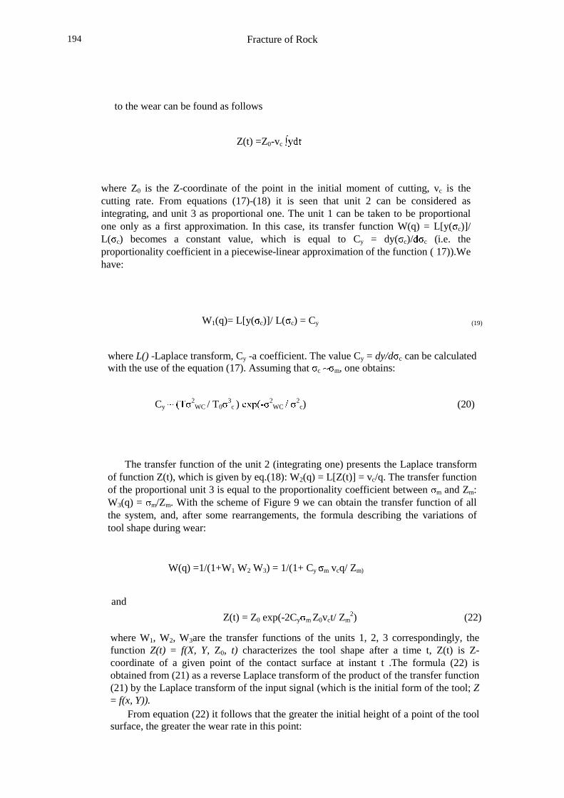
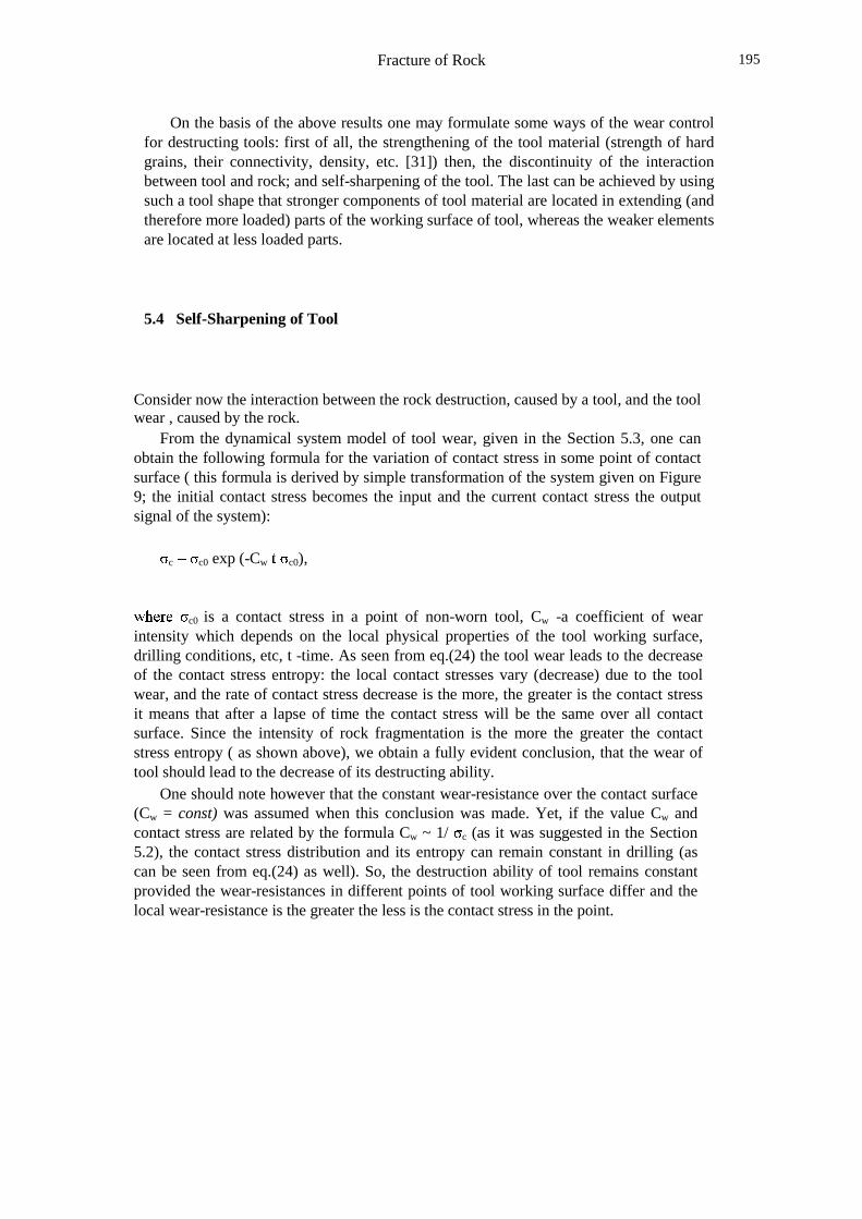
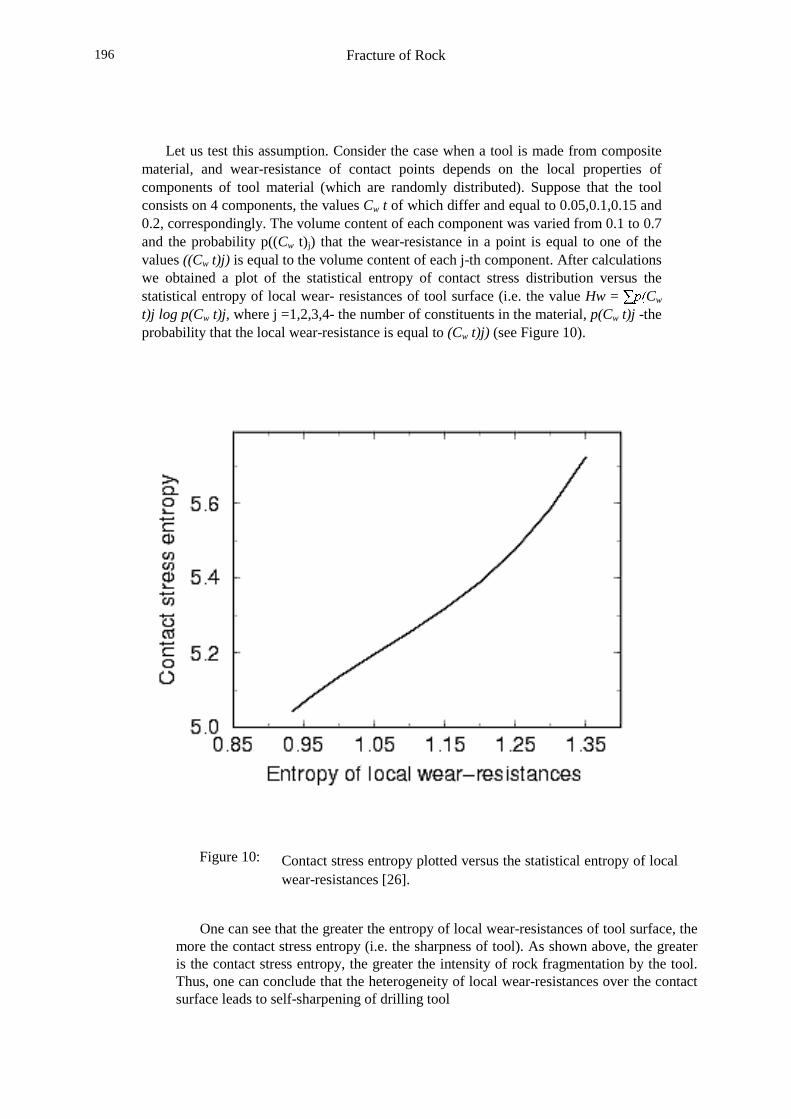
Let us test this assumption. Consider the case when a tool is made from compositematerial, and wear-resistance of contact points depends on the local properties ofcomponents of tool material (which are randomly distributed). Suppose that the toolconsists on 4 components, the values Cw t of which differ and equal to 0.05,0.1,0.15 and0.2, correspondingly. The volume content of each component was varied from 0.1 to 0.7and the probability p((Cw t)j) that the wear-resistance in a point is equal to one of thevalues ((Cw t)j) is equal to the volume content of each j-th component. After calculationswe obtained a plot of the statistical entropy of contact stress distribution versus thestatistical entropy of local wear- resistances of tool surface (i.e. the value Hw = ×ÙØEÚ Cw
t)j log p(Cw t)j, where j =1,2,3,4- the number of constituents in the material, p(Cw t)j -theprobability that the local wear-resistance is equal to (Cw t)j) (see Figure 10).
Figure 10: Contact stress entropy plotted versus the statistical entropy of localwear-resistances [26].
One can see that the greater the entropy of local wear-resistances of tool surface, themore the contact stress entropy (i.e. the sharpness of tool). As shown above, the greateris the contact stress entropy, the greater the intensity of rock fragmentation by the tool.Thus, one can conclude that the heterogeneity of local wear-resistances over the contactsurface leads to self-sharpening of drilling tool
Fracture of Rock 197
and may ensure also high destructing ability of the tool even after a lapse of time ofdrilling. Practically, it means that in order to ensure the high efficiency of rockfragmentation by a drilling tool during long time, the tool working surface should consiston a number of components with different wear-resistances.
6. Principle of Tool Design
The conclusion that an increase in the informational entropy of contact stress distributionleads to the improvement of destructing ability of tool was obtained in Section 5.1 on thebasis of the consideration of the elementary forms of indenters and then confirmednumerically. In Section 5.4 it was shown that the self-sharpening of the tool can beachieved if the wear-resistances of different points on the tool working surface are veryheterogeneous. In Section 5.2 it was shown that the arrangement of teeth on a drilling bitin pairs or in groups ensures higher efficiency of rock fragmentation.
If one generalizes these results, one may assume that introducing some heterogeneityinto a construction of tool (for instance, uneven distribution of contact stresses over thecontact area, heterogeneity of local wear-resistances or distances between teeth) leads tothe improvement of tool efficiency.
In order to verify this assumption, we use the Table 2 from [26], which presents aresult of an analysis of about 250 patents in the area of tool improvement. The analysis ofthe patents included the search of common approaches and ideas in different patents; as aresult of the analysis, the patents were divided into seven groups in correspondence withclose ideas used in the technical solutions.
Correlating the ideas from all of the groups, one can see that all considered methodsof tool improvement consist in introducing some heterogeneity (in other words,information) in tool constructions.
The groups 1 and 2 from this Table correspond fully to the main conclusionobtained in Section 5.1: the increase in the destructing ability of tool is achieved byincreasing the informational entropy of contact stress distribution. If one generalizes theresults of the patent analysis and the conclusions made in Sections 5.1-5.4, one canformulate the following general principle of drilling tool design: the efficiency of thedrilling tool increases with increasing the heterogeneity of distribution of localparameters of tool.
In terms of the information theory it can be formulated as follows: the efficiency of acomplex tool can be improved if the informational entropies of distributions of localparameters of the tool are increased.

Fracture of Rock198
Table 2:
Table 2. Technical solutions in the area of tool design [26]
Main Ideas Some Examples1. Unevenness of the tool work surface:making a cutting face convex or concave,or prismatic or cylindrical lugs oncutting face, stepped workingsurface; cavities, bevels, slopes
No 1044765A, 1023062A,No. 1323706A1, 623958 (USSR);No.1284539 (UR)No 57- 35357 (Japan)
2. Asymmetry of tool working surface aboutdirection of tool movement: a cuttingface or its parts are inclined ta cutting vector
723123 and 1046465A (USSR)
3. Using teeth of dissimilar shapes ororientations on the same bit: combination ofradial and tangential cutters, different cuttingand wedge angles on teeth from one bit, usingdifferent materials of inserts, the strength ofinserts changes from axis of auger toperiphery
No.395559, 153680A1,1366627 Al (USSR)
4. Irregular arrangement of teeth on a
bit: teeth or cutters are placed in pairsor in groups; various distance between teeth
No.3726350, 3158216 (USA)No. 1472623A1 (USSR)
5. Elements with different mechanisms ofloading on a bit are combined: combination ofmobile and fixed elements, or rotating andprogressively moving elements, or cutting andimpact elements
No.52-48082 (Japan)697711 (USSR)
6. Different wear-resistances or differentpoints or tool working surface: layers with
different strengths in a cutter;
diamond coatings and graded materials;cavities or required shape in tool
No.714003, 281349.145496, 693000, 609884 (USSR)
7. Self-sharpening and self-organization oftool
No.4230193 (USA)No. 717327, 719192 (USSR)
Fracture of Rock 199
References
1. Mishnaevsky Jr, L.L., Damage and Fracture of Heterogeneous Materials:Modeling and Application to the Improvement and Design of Drilling Tools ,Balkema, Rotterdam, 1997.
2. Mishnaevsky Jr, L.L. Physical mechanisms of hard rock fragmentation undermechanical loading: a review. Int. J. Rock Mech. Min. Sci. & Geomech. Abstr.32 (8), pp. 763-766, 1995
3. Lawn, B.R. & Wilshaw, T.R. Review indentation fracture: principles andapplications. J. Mater.Sci., 10, pp. 1049-1081, 1975
4. Eigheles, R.M. Rock Fracture in Drilling, Nedra, Moscow, 1971.
5. Shreiner, L.A. Physical Principles of Rock Mechanics. Gostoptekhizdat,
Moscow, 1950
6. Zhlobinsky, B.A. Dynamic Fracture of Rocks under Indentation, Nedra,
Moscow,19707. Blokhin, V .S. Improvement of Drilling Tool Efficiency. Tekhnika, Kiev, 1982
8. Artsimovich, G. V. Influence of the Face Conditions and Drilling Conditions onthe Efficiency of Cutting Deep Boreholes, Nauka, Novosibirsk, 1974.
9. Mishnaevsky Jr, L.L. Investigation of cutting of brittle materials. Int. J. MachineTools and Manufacture, 34 (4), pp. 499-505, 1994
10. Rzhevsky, V.V. & Novik, G.Ya. Principles of Physics of Rocks, Nedra,
Moscow, 198411. Sulakshin, S.S. 1964. Modem Methods of Rock Fragmentation in Hole Drilling.
Nedra, Moscow, 1964
12. Artsimovich, G.V., Poladko, E.P. & Sveshnikov, I.A. Investigation andDevelopment of Rock-Breaking Tool for Drilling. Nauka, Novosibirsk, 1978.
13. Artsimovich, G. V. Mechanical and Physical Principles of Design of RockBreaking Mining Tool. Nauka, Novosibirsk, 1985
14. Mavlyutov, M.R. Rock Fracture in Hole Drilling. Nedra, Moscow, 1978
15. Moskalev, A.N., Sologub, S.Ya., Vasilyev, L.M. & Mlodetskiy, V.P. In-crease of the Intensity of Rock Fragmentation. Nedra, Moscow, 1978
16. Rebinder, P.A., Shreiner, L.A. & Zhigach, K.F. Reducers of Hardness inDrilling. Moscow, Izd. AN SSSR, 1944
17. Staroselsky, A. V. & Kim, K.S. The effect of surface-active chemical agents onrock cutting with shear/drag bits, Rock Mechanics, eds. P. Nelson & S.Laubach, Balkema, Rotterdam, 1994
Fracture of Rock200
18. Kopylov, V.E. Hole Drilling outside the Earth. Nedra, Moscow, 1977
19. Stratonovich, R.L. Theory of Information. Sovetskoye Radio, Moscow, 1975
20. Mishnaevsky Jr, L.L. Methods of the theory of complex systems in modelingof fracture: a brief review. Eng. Fract. Mech., 56 (1) pp.47-56, 1997
21. Wilson, A.G. Entropy in Urban and Regional Modeling. Pion Ltd, Lon- don,
1970
22. Van der Bosch, P.P. J. & Van den Klauw, A.C. Modeling, Identification andSimulation of Dynamical Systems, CRC Press, London, 1994
23. Mishnaevsky Jr, L.L. Mathematical modeling of wear of cemented carbidetools in cutting brittle materials. Int. J. Machine Tools and Manufacture 35 (5),pp. 717-724, 1995
24. Lemaitre, J. A Course on Damage Mechanics, Springer, Berlin, 1992
25. Mishnaevsky Jr, L. and Schmauder, S. Damage evolution and localization inheterogeneous materials under dynamical loading: stochastic modeling,Computational Mechanics, 20 (7), pp.89-94, 1997
26. Mishnaevsky Jr, L.L. A new approach to the design of drilling tools. Int. J. RockMech. Min. Sci. & Geomech. Abstr. 33 (1), pp. 97- 102, 1996
27. Mishnaevsky Jr, L.L. & Schmauder, S. Damage evolution and heterogeneity ofmaterials: model based on fuzzy set theory, Eng. Fract. Mech. (in print)
28. Galin, L.A. Contact Problems in the Theory of Elasticity, ed. I.N. Sneddon.North Carolina State College, 1961
29. Mishnaevsky Jr, L.L. Determination for the time-to-fracture of solids. Int. J.Fracture 79 (4), pp. 341-350, 1996
30. Lippmann, H. Sense and nonsense of averaging stress and strain, Crystalplasticity modelling: abstracts of workshop. MPA, Stuttgart, 1996
31. Eigheles, R.M., Strekalova, R.M. & Mustafina. N .N .1975. Choice of optimalsizes of rock-destructing elements and their arrangement on the drilling bit.Rock Fragmentation, ed. R.M. Eigheles, pp. 136-150. VNIIBT , Moscow
32. Mishnaevsky Jr, L.L. A new approach to the analysis of strength ofmatrix composites with high content of hard fil1er. J. Appl. Comp. Mater. 1 pp.317-324, 1995