Embed Size (px)
Citation preview

Rock EngineeringRock EngineeringPractice & DesignPractice & Design
Lecture 7: Lecture 7: In SituIn Situ Stresses & Stresses & In SituIn Situ Stresses & Stresses & Stress MeasurementStress Measurement
1 of 47 Erik Eberhardt – UBC Geological Engineering ISRM Edition

Author’s Note:Author’s Note:The lecture slides provided here are taken from the course “Geotechnical Engineering Practice”, which is part of the 4th year Geological Engineering program at the University of British Columbia (V C d ) Th k i i d (Vancouver, Canada). The course covers rock engineering and geotechnical design methodologies, building on those already taken by the students covering Introductory Rock Mechanics and Advanced Rock Mechanics Rock Mechanics.
Although the slides have been modified in part to add context, they of course are missing the detailed narrative that accompanies any l l d h h l lecture. It is also recognized that these lectures summarize, reproduce and build on the work of others for which gratitude is extended. Where possible, efforts have been made to acknowledge th v ri us s urc s ith list f r f r nc s b in pr vid d t th the various sources, with a list of references being provided at the end of each lecture.
Errors, omissions, comments, etc., can be forwarded to the
2 of 47 Erik Eberhardt – UBC Geological Engineering ISRM Edition
Errors, omissions, comments, etc., can be forwarded to the author at: [email protected]

Why Study Stress?Why Study Stress?
Stress is a concept which is fundamental to rock mechanics principles and applications. There are three basic reasons to understand stress in the context of engineering rock mechanics:
There is a pre-existing stress state in the ground and we need to understand it, both directly and as the stress state applies to analysis and design.
During rock excavation, the stress state can change dramatically This is because rock which previously dramatically. This is because rock, which previously contained stresses, has been removed and the loads must be redistributed.
Stress is not familiar: it is a tensor quantity and tensors are not encountered in everyday life.
3 of 47 Erik Eberhardt – UBC Geological Engineering ISRM Edition

Why Determine Why Determine In SituIn Situ Stress?Stress?The basic motivations for in situ stress determination are two-fold:
Engineering analyses require 1 Failureg g y q
boundary conditions. One of the most important boundary conditions for the analysis of underground excavations is in situ stress
FoS=Strength
Stress
excavations is in-situ stress.
3
In Situ Stress State
T h b k l d To have a basic knowledge of the stress state (e.g. the direction and magnitude of the major principal of the major principal stress; the direction in which the rock is most likely to fail; etc.).
4 of 47 Erik Eberhardt – UBC Geological Engineering ISRM Edition

Presentation of In Situ Stress DataPresentation of In Situ Stress DataThe stress state at a point in a rock mass is generally presented in terms of the magnitude and orientation of the principal stresses (remember that the stress state is completely described by six
t )parameters).
Stress (MPa) Trend (º) Plunge (º)Sigma 1 10 210 70
Hudson & Harrison (1997)
gSigma 2 8 320 10Sigma 3 5 50 15
… principal stresses acting on a cube p p g(left), expressed in matrix form (centre), and shown on a hemispherical projection in terms of their orientation.
Need to know the in-situ stress in the plane of a tunnel for
5 of 47 Erik Eberhardt – UBC Geological Engineering ISRM Edition
plane of a tunnel for plane strain analysis.

In SituIn Situ StressStress
7)an
sson
(199
7
… components of rock stress and stress terminology de
i & S
teph
a
6 of 47 Erik Eberhardt – UBC Geological Engineering ISRM Edition
stress terminology.
Am
ad

In SituIn Situ StressStressWhen considering the loading conditions imposed on the rock mass, it must be recognized that an in situ pre-existing state of stress already exists in the rock.
89)
ck e
t al
.(19
8
… forces responsible for tectonic stresses.
Zoba
c
7 of 47 Erik Eberhardt – UBC Geological Engineering ISRM Edition

Estimation of Estimation of In SituIn Situ Stresses Stresses -- VerticalVerticalA fi t i ti th i i l i it t b As a first approximation, the principal in situ stresses can be assumed to act vertically (one component) and horizontally (two components).
The vertical stress component is assumed to increase with depth due to the weight of the overburden:
v = z
Where z is the depth measured in Where z is the depth, measured in metres below ground surface and is the unit weight, measured in MN/m3.
As a rule of thumb, taking the average density of rock into account, 40 m of overlying rock i d 1 MP t
8 of 47 Erik Eberhardt – UBC Geological Engineering ISRM Edition
induces 1 MPa stress.Hoek & Brown (1980)

Estimation of Estimation of In SituIn Situ Stresses Stresses -- HorizontalHorizontalTh h i t l t b ti t d i f l ti th If The horizontal stress can be estimated using of elastic theory. If we consider the strain along any axis of a small cube at depth, then the total strain can be found from the strain due to the axial stress subtracting the strain components due to the two axial stress, subtracting the strain components due to the two perpendicular stresses.
For example:
H2H1VV
EEE
VH2H1
V
EEEVH2H1
H1
9 of 47 Erik Eberhardt – UBC Geological Engineering ISRM Edition
Hudson & Harrison (1997)

Estimation of Estimation of In SituIn Situ Stresses Stresses -- HorizontalHorizontal
To provide an initial estimate of the horizontal stress, two assumptions are made:
the two horizontal stresses are equal;
there is no horizontal strain, i.e. both H1 and H2 are zero
0 VH2H1
, H1 H2(e.g. because it is restrained by adjacent elements of rock).
Then we can take as zero: EEE
0 VH2H1 Then we can take H1 as zero:
And, because H1 = H2 : VH -1
10 of 47 Erik Eberhardt – UBC Geological Engineering ISRM Edition

Estimation of Estimation of In SituIn Situ Stresses Stresses -- HorizontalHorizontal
Thus the ratio between the horizontal and vertical stress (referred to as K = / ) is a (referred to as K = H/V) is a function of the Poisson’s ratio:
-1V
H
For a typical Poisson’s ratio () of 0.25, the resulting K ratio is 0.33. For a theoretical maximum of =
H k & B (1980)
For a theoretical maximum of = 0.5, the maximum K ratio predicted is 1.0.
11 of 47 Erik Eberhardt – UBC Geological Engineering ISRM Edition
Hoek & Brown (1980)

In SituIn Situ Stresses Stresses –– Canadian DatabaseCanadian Database
H
v
Compiled by CANMET: Measurements to 2500 m Thrust FaultsH > v
Martin & Chandler (1993)
12 of 47 Erik Eberhardt – UBC Geological Engineering ISRM Edition
H v

In SituIn Situ Stresses & Geological StructureStresses & Geological StructureDi ti iti f lt t t Discontinuities, e.g. fault zones, act to dramatically perturb the stress field and thus the magnitudes and orientations of the principal stresses. This may lead to p p ybias if the stress measurements are made near an isolated fracture.
dler
(199
3)rt
in &
Cha
nd
13 of 47 Erik Eberhardt – UBC Geological Engineering ISRM Edition
Mar
Reasons for High Horizontal StressesReasons for High Horizontal Stresses
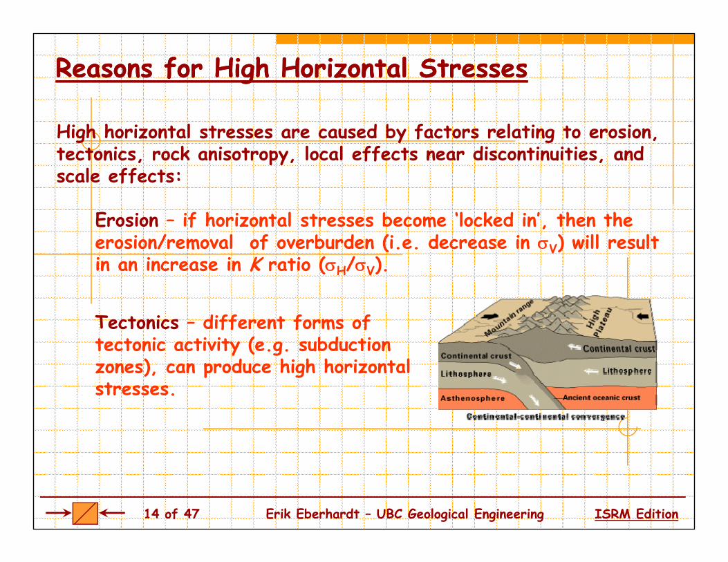
High horizontal stresses are caused by factors relating to erosion, tectonics, rock anisotropy, local effects near discontinuities, and scale effects:scale effects:
Erosion – if horizontal stresses become ‘locked in’, then the erosion/removal of overburden (i e decrease in V) will result erosion/removal of overburden (i.e. decrease in V) will result in an increase in K ratio (H/V).
T t i diff t f f Tectonics – different forms of tectonic activity (e.g. subduction zones), can produce high horizontal stressesstresses.
14 of 47 Erik Eberhardt – UBC Geological Engineering ISRM Edition

Methods of Stress DeterminationMethods of Stress DeterminationAny system utilized for estimating in situ stresses should involve a Any system utilized for estimating in situ stresses should involve a minimum of six independent measurements. Accordingly, there are methods of ‘direct’ stress measurement and there are methods of estimating the stresses via ‘indirect’ or ‘indicator’ methods.estimating the stresses via indirect or indicator methods.
97)
hans
son
(199
mad
ei &
Ste
p
15 of 47 Erik Eberhardt – UBC Geological Engineering ISRM Edition
Am

Indicator Methods of Stress DeterminationIndicator Methods of Stress Determination
By careful study of earthquake waves recorded earthquake waves recorded by seismographs, it is possible to tell the direction of motion of the fault that of motion of the fault that caused the earthquake.
By analyzing the earthquake y y g qfault-plane solution (i.e. focal mechanism), a best fit regional stress tensor can be determined by means of an inversion technique.
Amadei & Stephansson (1997)
16 of 47 Erik Eberhardt – UBC Geological Engineering ISRM Edition

Indicator Methods of Stress DeterminationIndicator Methods of Stress Determination
The rock around a circular excavation may not be able to sustain the compressive stress concentration induced during excavation. Failure of the rock results in zones of enlargement called g‘breakouts’. There is experimental evidence that breakouts occur in the direction parallel to the minimum in situ stress component.
17 of 47 Erik Eberhardt – UBC Geological Engineering ISRM Edition
Amadei & Stephansson (1997)

Indicator Methods of Stress DeterminationIndicator Methods of Stress Determination
3 = 14 MPa final shapestages in notch
1 = 55 MPa
stages in notchdevelopment
97)
i i i tin
et a
l. (1
99
… stress-controlled tunnel breakout at the URL in Canada.
microseismicevents M
art
18 of 47 Erik Eberhardt – UBC Geological Engineering ISRM Edition
… str ss contro tunn r a out at th U L n ana a.

World Stress MapWorld Stress Map
19 of 47 Erik Eberhardt – UBC Geological Engineering ISRM Edition

World Stress Map World Stress Map –– North AmericaNorth America
20 of 47 Erik Eberhardt – UBC Geological Engineering ISRM Edition

Methods of Stress DeterminationMethods of Stress Determination
Huds n & H rris n (1997)
… the four ISRM suggested methods for rock stress determination and their ability to determine the 6 independent components of the t t t t/ li ti f th ti l th d
Hudson & Harrison (1997)
21 of 47 Erik Eberhardt – UBC Geological Engineering ISRM Edition
stress tensor over one test/application of the particular method.
Flatjack MethodFlatjack Method
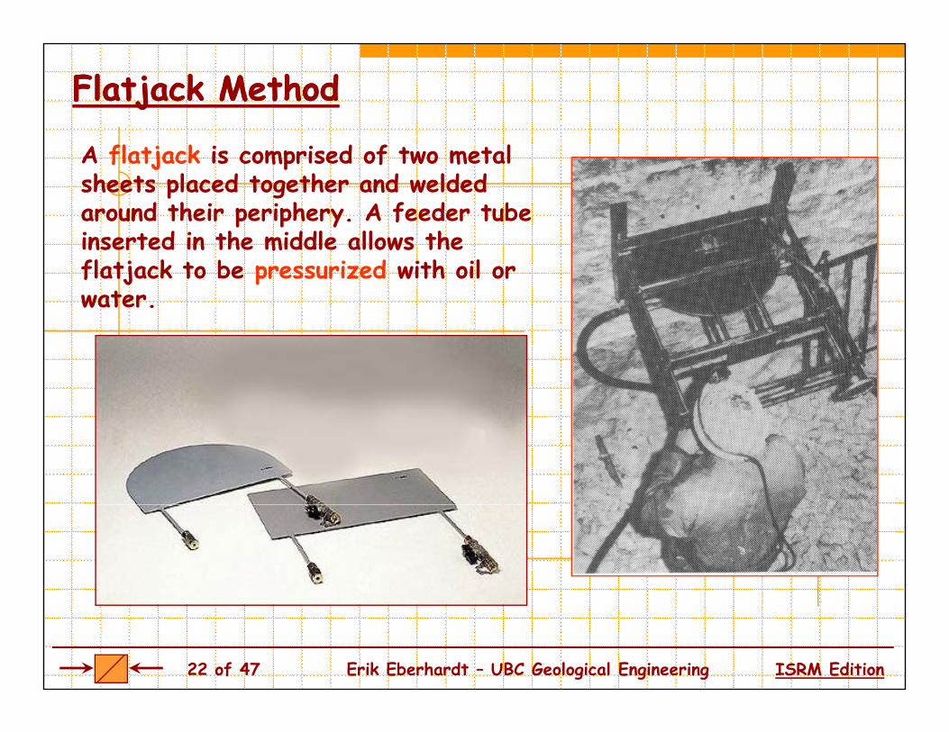
A flatjack is comprised of two metal sheets placed together and welded around their periphery. A feeder tube inserted in the middle allows the flatjack to be pressurized with oil or water.
22 of 47 Erik Eberhardt – UBC Geological Engineering ISRM Edition

Flatjack MethodFlatjack Method
The flatjack method involves the placement of two pins fixed into the wall of an excavation. The distance, d, is then measured accurately A slot is cut into the rock between the measured accurately. A slot is cut into the rock between the pins. If the normal stress is compressive, the pins will move together as the slot is cut. The flatjack is then placed and grouted into the slot.g
23 of 47 Erik Eberhardt – UBC Geological Engineering ISRM Edition
Hudson & Harrison (1997)

Flatjack MethodFlatjack Method
On pressurizing the flatjack, the pins will move apart. It is assumed that, when the pin separation distance reaches the value it had before the slot was cut the force exerted by the flatjack it had before the slot was cut, the force exerted by the flatjack on the walls of the slot is the same as that exerted by the pre-existing normal stress.
Hudson & Harrison (1997)
24 of 47 Erik Eberhardt – UBC Geological Engineering ISRM Edition

Flatjack MethodFlatjack Method
The major disadvantage with the system is that the necessary minimum number of 6 tests, at different orientations, have to be conducted at 6 different locations and it is therefore necessary to ydistribute these around the boundary walls of an excavation.
997)
Har
riso
n (1
9H
udso
n &
It is also important to note that the excavation from which the tests are made will disturb the pre-existing stress state, and so the new redistribution of stresses should be accounted for.
25 of 47 Erik Eberhardt – UBC Geological Engineering ISRM Edition

FlatjackFlatjack Method Method –– Example ProblemExample Problem
Q. Three flatjack tests have been made along a tunnel wall, the axis of which dips at 7º The measurement position is at 7 . The measurement position is approximately 250 m below ground surface. The slots for the flatjacks were cut normal to the wall as shown. The cancellation pressures for each flatjack were: A = 7.56 MPa; B = 6.72 MPa; C = 7.50 MPa. Compute the principal stresses
Harrison & Hudson (2000)
and their directions.
A. One way of solving this problem is to use the stress y f g ptransformation equations, i.e.:
26 of 47 Erik Eberhardt – UBC Geological Engineering ISRM Edition
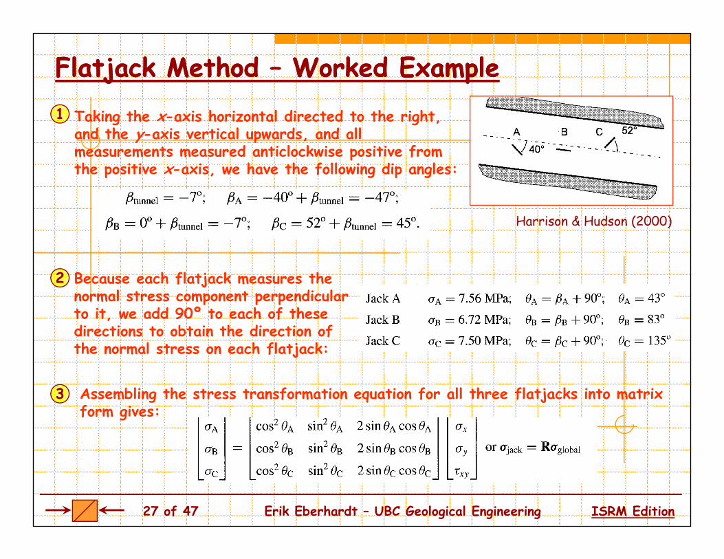
FlatjackFlatjack Method Method –– Worked ExampleWorked ExampleTaking the x-axis horizontal directed to the right, and the y-axis vertical upwards, and all measurements measured anticlockwise positive from the positive x-axis, we have the following dip angles:
1
the positive x axis, we have the following dip angles
Harrison & Hudson (2000)
Because each flatjack measures the normal stress component perpendicular to it we add 90º to each of these
2
to it, we add 90 to each of these directions to obtain the direction of the normal stress on each flatjack:
3 Assembling the stress transformation equation for all three flatjacks into matrix form gives:
27 of 47 Erik Eberhardt – UBC Geological Engineering ISRM Edition

FlatjackFlatjack Method Method –– Worked ExampleWorked Example
Evaluation of this matrix gives:4
Which upon inversion gives global = R-1jack, or:
From this we find: We see that x and y are principal stresses, because xy = 0, and the principal stresses are
5
p pvertical and horizontal, which is a reasonable finding.
Note that the horizontal stress, x, is greater than the vertical stress, y, h h f h h f h
son
(200
0)
ywhich is a common occurrence. Now if we were to compare the weight of the overburden to the computed vertical stress value:
riso
n &
Hud
s
28 of 47 Erik Eberhardt – UBC Geological Engineering ISRM Edition
This compares well with the value found for y. Har

Hydraulic Fracturing MethodHydraulic Fracturing Method
Th h d li f i The hydraulic fracturing method involves the pressuring of a borehole interval typically 1 m interval, typically 1 m long, isolated using a straddle packer system. The isolated zone is The isolated zone is pressurized by water until a fracture occurs in the rock.
Amadei & Stephansson (1997)
29 of 47 Erik Eberhardt – UBC Geological Engineering ISRM Edition
Amadei & Stephansson (1997)

Hydraulic Fracturing MethodHydraulic Fracturing Method
The two measurements taken are the water pressure when the fracture occurs and the subsequent pressure required to hold the fracture open These are referred to as the breakdown pressure fracture open. These are referred to as the breakdown pressure (Pc
’ or PB) and the shut-in pressure (Ps).
1st breakdown pressure
2nd breakdown pressure
3rd breakdown pressure
fluid pressure in formation
30 of 47 Erik Eberhardt – UBC Geological Engineering ISRM Edition
Amadei & Stephansson (1997)

Hydraulic Fracturing MethodHydraulic Fracturing Method
In calculating the in situ stresses, the shut-in pressure (Ps) is assumed to be equal to the minor horizontal
Relationships
h = Psqstress, h.
The major horizontal stress, H, is t = Pc’-Pr
h Ps
H = 3h–Pc’-Po+ t
then found from the breakdown pressure (Pc
’ or PB). In this calculation, the breakdown pressure h t th i h i t l
H = 3h–Pr-Po
has to overcome the minor horizontal principal stress (concentrated three times by the presence of the borehole) and overcome the in situborehole) and overcome the in situtensile strength of the rock; it is assisted by the tensile component of the major horizontal principal stress.
31 of 47 Erik Eberhardt – UBC Geological Engineering ISRM Edition
the major horizontal principal stress.Hudson & Harrison (1997)

Hydraulic Fracturing MethodHydraulic Fracturing Method
The analysis assumes that the induced fracture has propagated in a direction perpendicular to the minor principal stress. p p p p
Other assumptions include that of elasticityin the rock forming the borehole wall (from h h h b h l which the borehole stress concentration
factor of three is derived), and impermeability of the host rock so that pumped water has not significantly pumped water has not significantly penetrated the rock and affected the stress distribution.
The tensile strength of the rock can be obtained from test performed by pressurizing hollow rock cylinders.
32 of 47 Erik Eberhardt – UBC Geological Engineering ISRM Edition
pr ssur z ng ho ow roc cy n rs.

Hydraulic Fracturing Method Hydraulic Fracturing Method -- HTPFHTPF
The HTPF method (Hydraulic Testing on Pre-existing Fractures) consists of reopening Fractures), consists of reopening an existing fracture of known orientation that has previously been isolated in between two packers. By using a low fluid injection rate, the fluid pressure which balances exactly the normal stress across the fracture is measured.
Th m th d i th n p t d f The method is then repeated for other non-parallel fractures of known orientation. Amadei & Stephansson (1997)
33 of 47 Erik Eberhardt – UBC Geological Engineering ISRM Edition

Hydraulic Fracturing Method Hydraulic Fracturing Method -- HTPFHTPF
By determining the normal stressesacting across several non-parallel fractures and knowing their orientation fractures and knowing their orientation, a system of equations can be created to determine the six in situ stress components without making any components without making any assumption with regards to the orientation of the principal stresses and the rock’s constitutive behaviour.
It is the only hydraulic method that does not have to assume that the
l l principal stress directions are aligned vertically and horizontally.
34 of 47 Erik Eberhardt – UBC Geological Engineering ISRM Edition
Cornet (1993)

Hydraulic Fracturing Method Hydraulic Fracturing Method –– Worked ExampleWorked ExampleQ. A hydraulic fracture test in a granite rock mass yield the following results:
Given that the tensile strength of the rock is 10 MPa, estimate the principal
A
g , p pstresses assuming one is vertical and that the pressure values were adjusted to account for the formation pressures (i.e. Po=0 for calculation purposes).
Assuming that the rock mass was behaving as an elastic material A. Assuming that the rock mass was behaving as an elastic material...
Relationshipsh = Ps
h = Ps = 8 MPaCalculate the min. horizontal stress: 1
0H = 3h–Pc’-Po+ t
2 H = 3h–Pc’-Po+ tCalculate the max. horizontal stress:
H = 20 MPaH = 3(8 MPa) – 14 MPa + 10 MPa
3 Th v rtic l str ss c n n b 3 The vertical stress can now be estimated from the overburden (assume = 27 kN/m3 for granite): V = 500m * 0.0027 MN/m3 = 13.5 MPa
35 of 47 Erik Eberhardt – UBC Geological Engineering ISRM Edition
1 = H = 20 MPa 2 = v = 13.5 MPa 3 = h = 8 MPa

Borehole Relief Methods Borehole Relief Methods -- OvercoringOvercoring
The main idea behind relief methods is to isolate (partially or wholly) a rock sample from the stress field rock sample from the stress field that surrounds it and to monitor the response. As such, the stresses are not related to applied pressures, pp p ,such as with the hydraulic tests. Instead, the stresses are inferred from strains generated by the relief (1
997)
(unloading) process and measured directly on the rock associated with the relief process.
teph
anss
on (
Overcoring methods are by far the most commonly used relief method.
Am
adei
& S
t
36 of 47 Erik Eberhardt – UBC Geological Engineering ISRM Edition

Overcoring MethodOvercoring MethodFirst, a large diameter borehole is drilled (between 60 and 220 mm) to a sufficiently large distance so that stress effects due to any excavations can be neglectedany excavations can be neglected.
Second, a small pilot hole (e.g. 38 mm) is drilled. The measuring device is then inserted
d f d i hi h land fastened in this hole.
Thirdly, the large diameter hole is resumed, relieving stresses and strains in the hollow rock relieving stresses and strains in the hollow rock cylinder that is formed. Changes in strain are then recorded with the instrumented device as the overcoring proceeds past the plane of m m ntmeasurement.
Following overcoring, the recovered overcore (containing the instrumented device) is then tested in a biaxial chamber to
37 of 47 Erik Eberhardt – UBC Geological Engineering ISRM Edition
nstrum nt c ) s th n t st n a a a cham r to determine the elastic properties of the rock.

Overcoring Method Overcoring Method –– USBM Deformation ProbeUSBM Deformation Probe
The USBM technique (from the U.S. Bureau of Mines) allows the complete stress state to be determined from three measurements in boreholes with different orientations when the stresses are released by overcoring the borehole.
When the probe is inserted in a borehole, six ‘buttons’ press h b h l ll d h d l d against the borehole wall and their diametral position is measured
by strain gauges bonded to steel cantilevers supporting the buttons.
38 of 47 Erik Eberhardt – UBC Geological Engineering ISRM Edition

Overcoring Method Overcoring Method –– USBMUSBM
When the borehole is overcored by a larger diameter borehole, the stress state in the resulting hollow cylinder state in the resulting hollow cylinder is reduced to zero, the diameter of the hole changes, the buttons move, and hence different strains are on
(199
7)
and hence different strains are induced in the strain gauges.
From these changes, and with the
son
& H
arri
so
guse of elasticity theory, the biaxial stress state in the plane perpendicular to the borehole axis is d d d
Hud
s
deduced.
39 of 47 Erik Eberhardt – UBC Geological Engineering ISRM Edition

Overcoring Method Overcoring Method –– USBMUSBM
A useful aspect of this technique is that it produces technique is that it produces an annular core which may be used in the laboratory to determine the elastic properties directly.
Given the validity of the assumptions, the USBM probe is efficient because it is reusable, permit measurements to be made many times within a borehole and are relatively cheap and robust.
However, the analysis can be complicated by the presence of the borehole, which perturbs the stress state from its natural in situ t t
40 of 47 Erik Eberhardt – UBC Geological Engineering ISRM Edition
state.

Overcoring Method Overcoring Method –– CSIRO Hollow Inclusion Cell CSIRO Hollow Inclusion Cell The CSIRO device operates on a similar principle to the USBM probe except that it is a gauge which is glued into the borehole and can measure normal strains at a variety of orientations and l ti d th b h l ll locations around the borehole wall.
The gauge is glued into position within the pilot hole, initial readings of strain are taken and the gauge is then overcored
41 of 47 Erik Eberhardt – UBC Geological Engineering ISRM Edition
readings of strain are taken and the gauge is then overcored.

Overcoring Method Overcoring Method –– CSIRO Hollow Inclusion Cell CSIRO Hollow Inclusion Cell
Overcoring destresses the resulting hollow cylinder and final strain gauge
di k Th h readings are taken. The gauge has either 9 or 12 separate strain gauges, in rosettes of three, so there is some redundancy in the there is some redundancy in the measurements- thus permitting statistical analysis of the data.
Alternatively, if the rock is assumed to be anisotropic (e.g. transverse isotropic), then the extra readings p ), gallow the stress state to be calculated incorporating the rock anisotropy.
42 of 47 Erik Eberhardt – UBC Geological Engineering ISRM Edition
Amadei & Stephansson (1997)

Overcoring Method Overcoring Method –– CSIRO Hollow Inclusion Cell CSIRO Hollow Inclusion Cell
The CSIRO measurement cell is one of the few tests that can establish the full stress tensor with one installation.
Another advantage of the method is that the hollow rock cylinder can be retrieved and tested under controlled conditions in
d t d t i th l ti t torder to determine the elastic constantsand the functionality of the system (e.g. whether strain gauges are properly bonded, whether the test was performed
One major problem is the environment within the borehole: water or loose
, pin intact rock, etc.).
within the borehole: water or loose material on the borehole walls may hamper bonding of the cell; and drilling fluids may generate temperature effects.
43 of 47 Erik Eberhardt – UBC Geological Engineering ISRM Edition
y g p

Case History: Lower Case History: Lower KihansiKihansi Hydropower ProjectHydropower ProjectThe Lower Kihansi hydroelectric project in Tanzania seeks to utilise the waters of the Kihansi the waters of the Kihansi river by channelling part of the river flow upstream of the Kihansi
ll l d h h Falls into an inclined high pressure headrace tunnel. The headrace tunnel was planned to be tunnel was planned to be largely unlined.
Unlined tunnels cost 3 to 5 times less than lined tunnels; in this case a cost savings on the order of $10-15 million.
44 of 47 Erik Eberhardt – UBC Geological Engineering ISRM Edition

Case History: Lower Case History: Lower KihansiKihansi Hydropower ProjectHydropower Project
To permit this, the minimum p m , m n mumprincipal stress along the tunnel trajectory under operational conditions would have to be at least equal to have to be at least equal to the water head times a 1.2 safety factor.
3)ø
et a
l.(2
00
45 of 47 Erik Eberhardt – UBC Geological Engineering ISRM Edition
Dah
lø

Case History: Lower Case History: Lower KihansiKihansi Hydropower ProjectHydropower Project
minimum for unlined tunnel
(200
3)D
ahlø
et a
l.
Minimum principal stress estimates indicated levels of at least 9.5MPa, increasing to 10.2–11.6 MPa after correction for drainage during testing ( h d h 10 P h h ld d f l d l)
46 of 47 Erik Eberhardt – UBC Geological Engineering ISRM Edition
(thus exceeding the 10 MPa threshold required for an unlined tunnel).

Lecture ReferencesLecture ReferencesAmadei, B & Stephansson, O (1997). Rock Stress and its Measurement. Chapman & Hall: London.
Cornet FH (1993). The HTPF and the integrated stress determination methods. In ComprehensiveRock Engineering. Pergamon Press: Oxford, vol. 3, pp. 413–32
Dahlø T Evans KF Halvorsen A & Myrvang A (2003) Adverse effects of pore pressureDahlø, T, Evans, KF, Halvorsen, A & Myrvang, A (2003). Adverse effects of pore-pressuredrainage on stress measurements performed in deep tunnels: an example from the Lower Kihansihydroelectric power project, Tanzania. International Journal of Rock Mechanics and Mining Sciences40(1): 65-93.
Harrison JP & Hudson JA (2000) Engineering Rock Mechanics Part 2: Illustrative WorkedHarrison, JP & Hudson, JA (2000). Engineering Rock Mechanics – Part 2: Illustrative WorkedExamples. Elsevier Science: Oxford.
Hoek, E & Brown, ET (1980). Underground Excavations in Rock. Institution of Mining andMetallurgy: London.
Hudson, JA & Harrison, JP (1997). Engineering Rock Mechanics – An Introduction to the Principles .Elsevier Science: Oxford.
Martin, CD & Chandler, NA (1993). Stress Heterogeneity and geological structures. InternationalJournal of Rock Mechanics and Mining Sciences & Geomechanics Abstracts 30(7): 993-999.f g ( )
Martin, CD, Read, RS & Martino, JB (1997). Observations of brittle failure around a circular testtunnel. International Journal of Rock Mechanics and Mining Sciences 34(7): 1065-1073.
Zoback, ML, Zoback, MD, et al. (1989). Global patterns of tectonic stress. Nature 341(6240):291 298
47 of 47 Erik Eberhardt – UBC Geological Engineering ISRM Edition
291-298.