Embed Size (px)
Citation preview

PATENT PENDING VERSION 2020-03-27
1
RoCC Kiln Manual:
(version 2020-03-27)
Rotatable Covered Cavity Kilns for Pyrolytic Production of
Biochar for Sequestration and Woodgas for Energy (BC&E)
© Copyright 2020 by Paul S. Anderson
Paul S. Anderson, PhD, President
Woodgas Pyrolytics, Inc. 227 South Orr Drive
Normal, Illinois 61761 USA
Email: [email protected] Corp. website: www.woodgas.com (being developed)
Personal website: www.drtlud.com Phones: 309-452-7072 (office)
309-531-4434 (mobile & text)

PATENT PENDING VERSION 2020-03-27
2
Table of Contents Part One: Overview Preamble Important Notices Introduction Short Description Overview of this RoCC Booklet Summary of other pyrolysis technology
Part Two: Problem and Perspective Introduction about: Problems and Perspectives: Seven major CDR approaches Biomass supply Perception, Process and Advantages Sizes and Tasks Calculations and Projections (See Appendices for more detailed discussions.)
Part Three: Descriptions Summary of RoCC Kiln Construction
Part Four: Components 1. Covered cavity kiln 2. Portal 3. Handle / method for rotation 4. Support rack for rotation (with possible combination with #9, becoming one frame.) 5. Wheels or casters 6. Support for axle of rotation 7. Hood for emissions 8. Chimney(s) 9. Support frame for the hood / chimney component (w/ possible combination to #4) Eight types of auxiliary components: 12. Fuel input feeder shelf (horizontal or inclined) 13. Fuel input bulk feeder or bin 21. Charcoal extraction slides 22. Charcoal extraction trays / char extinguishers 23. Prongs for sifting contents (at portal) 24. Enhancers of internal mixing 25. Pipes (include injection and disruption) 26. Sensors / regulators
Part Five: Specifics for Fabrication Introductory comments only. Contact Dr. Anderson for specific assistance about: Units with Axle: Model: Barrel - 55-G (aka RoCC 200 liter) 55-gallon barrel-size RoCC Pyrolyzer with Axle Units with Rollers: Model: 3 – 4’ Dia. – 5 – 10 ‘ Long Larger RoCC units with Rollers Part Six: Operations and Usage
Part Seven: Patent & Business Topics Patent issues Patent Provisions (Especially this section is subject to changes)
Part Eight and Beyond More to Come? (Certainly!!)
Appendices A. Comparison of Flame Cap (FC or Open Cavity) and RoCC technologies [PowerPoint] B. Major CDR Approaches C. Biomass Supply D. Perception, Process and Advantages: E. Size and Scale
F. Calculations and Projections

PATENT PENDING VERSION 2020-03-27
3
List of Figures Figure 1.1 Introductory sketch and image of RoCC devices Figure 1.2 Three copied slides A, B, C of pyrolysis technologies Figure 1.3 Multiple profit centers from pyrolysis Figure 2.1 Major types of CDR Figure 2.2 Quantified Carbon Cycle Figures 4.1 to 4.3 Views of RoCC kiln at IMMT, Odisha, India Figure 4.4 Portal positions on a cylindrical covered cavity kiln Figure 4.5 Views of prongs and flanges at the portal for sifting / sorting the product. Figure 4.6 Grate positions Figure 4.7 Enhancers of internal mixing, including pipes and sensors Provisional Figures 5.1 to 5.4 showing the RoCC pyrolyzer kiln, at Berkeley Olive Grove, near Oroville, California 28 Feb 2020
List of Tables
Table 2.1 Size and likely use options for RoCC kilns (subset only here) (Full Table in Appendix E) Table E.1. Sizes and likely uses of RoCC kilns Table E.2 Sizes of RoCC Char Makers (from the PowerPoint in Appendix A.)

PATENT PENDING VERSION 2020-03-27
4
Part One: Overview 1.1 Preamble in February 2020: Our world needs many contributing solutions to confront the interrelated crises of energy, food and climate change. One solution is to obtain both carbon neutral energy and storage of atmospheric carbon dioxide that has been extracted by renewable biomass fuel, referred to as Biochar & Energy (BC&E). The process called pyrolysis is natural, well understood, and available in devices as small as US$40 household cookstoves in India and as large as pyrolytic kilns costing hundreds of thousands of dollars. But medium-size units have been notably absent or rather limited. Without the medium-size technology, the challenge remains to cumulatively process hundreds of millions of tons per year of woody biomass and crop residues that are thinly spread around the world. This manual is about a new pyrolytic technology with methods and devices in the desired medium-size range. R&D units under 4-ft diameter for “proof of concept” are already showing great prospects. Further R&D with units of 6-ft and larger diameters will lead to heating systems for schools, apartment blocks and organized districts while producing tons of environmentally stable charcoal to be spread as CDR (Carbon Dioxide Removal) biochar for soil enhancement for increased food production. That is a win-win-win-…. win-win situation. Such transitions create jobs for biomass supply, equipment manufacturing, and support services for all the uses of the heat and biochar and chemical extractions, as well as reduction of unwanted fire-hazard excess biomass. Such transformative changes will require the full range of human skills from eventually millions of people worldwide. The starting point is an invention of a technology for medium-size pyrolysis with low costs and high benefits. With patent pending status, the technology is being introduced in this RoCC Kiln Manual. Major problems can have simple solutions. An example of simple is be a covered cavity kiln that is rotatable on demand. It is a Rotatable Covered Cavity Kiln, an RoCC kiln or pyrolyzer. It provides improved control of pyrolysis of biomass. The invention exists, and mechanical and industrial engineering can add the refinements and complexities for optimal usage. Economics and business can facilitate RoCC kiln adaptation. And societal need for energy and climate remediation can lead to widespread impacts.
1.2 Important Notices: (Including guidelines for further efforts.) (Draft dated 2020-
03-12)
Please read these Notices and the Introduction that follows. After that, there is no particular order for reading the various Parts and Sections of this RoCC Kiln Manual. 1. I claim to have an invention that should have major benefits for society regarding world climate, local environments, energy supplies, and even food production via pyrolysis that produces woodgas energy and biochar for sequestration into soil. 2. I am providing this manual as early information to a limited selection of persons with probable involvement. This is an introductory document with a request for your comments. There will be more complete technical details about fabrication and use of the invention in subsequent documents for those who express interest. 3. With the protection of patent pending status, there is no requirement for signing of non-disclosure agreements, but readers (you) are requested not to make public disclosure of these documents until further progress is made and announced by me.

PATENT PENDING VERSION 2020-03-27
5
4. It is my intention to eventually widely distribute the RoCC kiln technology for maximum impact while retaining rights to some financial returns if and when others are receiving financial / business gains from the RoCC invention. 5. If you are interested in making and using the Rotatable Covered Cavity (RoCC) Kiln technology, please be in contact with me. That is a good way to have my support and appropriate recognition for your efforts that might be making history or reaching new geographic areas or special types of biomass. Or I can help you to avoid replicating efforts already known to not work well. 6. I am trying to keep people informed, such as about planned demonstrations and the release of further documents. There is more information than what is in this edition of the RoCC Kiln Manual. But to provide the best and most up to date info to those who truly want it, I do need to know who wants to be kept informed. 7. Contact me at [email protected] for further information and for business discussions about benefits for companies, communities, the environment and world climate. At a later date, notifications will be posted at www.woodgas.com the website of Woodgas Pyrolytics, Inc. Paul S. Anderson 2020-03-27
1.3 Introduction This RoCC Kiln Manual is a work-in-progress that will grow throughout 2020. Each of its Parts and Appendices is subject to individual editing and expansion. This introduction is to set the stage and to help direct you to the sections that you might want.
1.3.1 The RoCC pyrolyzer invention [Short Description in 13 Words:] The RoCC pyrolyzer is a covered cavity kiln (that controls the air supply and pyrolysis process) that is rotatable on demand (to accomplish the physical mixing of the contents to assure exposure to the required heat of pyrolysis). [A much more complete description is in Part Three, Section 3.1.] Figure 1.1 Introductory sketch and image of RoCC devices There are two main variations. One is with rotation with a central axle. (Left image) The other has the kiln supported on rollers so that it can be rotated. (Right image) A more complete explanation is in Part 3. Details for construction are provided in Part Four and Part Five (and from Dr. Anderson for the most up-to-date versions).

PATENT PENDING VERSION 2020-03-27
6
1.3.2 A summary of pyrolytic production of biochar prior to the RoCC kiln invention. Paul Anderson made a PowerPoint presentation at the 1 July 2919 conference of the US Biochar Initiative with an overview of earlier efforts by him and others. That presentation is available at http://www.slideshare.net/bitmaxim/farmscale-char-production-affordable-4c-kilns-for-biochar . Some edited improvement are at woodgas.com/resources . The RoCC kiln is not discussed in that presentation. Figure 1.2 Three copied slides A, B, C of pyrolysis technologies Slide 1.2.A Slide 4 from document Slide 1.2.B Slide 5 from document Slide 1.2.C Slide 7 from document Please note that the 19 July 2019 demonstration of the oblong kiln shown in Slides 14 and 21 was not sufficiently successful to proceed with that design.

PATENT PENDING VERSION 2020-03-27
7
1.3.3 The utility of Pyrolysis, the basis of Biochar & Energy (BC&E) as a CDR technology Figure 1.3 Multiple profit centers from pyrolysis
1.3.4 The utility of the RoCC kiln invention: The RoCC technology makes charcoal (biochar) in moderate and mid-size quantities in relatively low-cost devices with better prospects for cleaner emissions (than with open-top cavity kilns (“flame-cap”) and improved capture of the thermal energy or pyrolytic gases (chemicals) The RoCC methods and devices can use a wide variety of biomass feedstock with generally less transportation costs and increased prospects to be financially viable.
1.3.5 Problems that could be (at least partially) solved include: See Part 2 and Appendix B. Climate change is the elephant in the room that must somehow be managed. Carbon Dioxide Removal (CDR) has ~7 major categories of technologies Biochar & Energy (BC&E) is one of those categories and is closest to implementation. RoCC pyrolysis fits into an empty niche for BC&E success

PATENT PENDING VERSION 2020-03-27
8
Traditional charcoal production is wasteful and could be replaced with RoCC kilns. (see box)
1.3.6 Sufficient supply of Biomass (See Section 2.2 and further details in Appendix C.) The annual availability of dry biomass for societal use is in the tens of gigatons. The USA alone has between 1 and 1.5 billion tons (1 – 1.5 Gt) of available dry biomass each year without impact on food or fiber production. The biomass is relatively thinly distributed, appropriate for use in RoCC kiln.
1.3.7 The latest details for RoCC kiln fabrication (See Part Five of this RoCC Kiln Manual) Progress can occur rapidly in the early months of an invention. The latest details are directly with Dr. Anderson. Updating documents always lags behind the actual experiences. Specific information released as of the date of this manual is provided about building RoCC kilns with axle support using 55-gallon barrels and also about RoCC kilns that use support rollers. Please consider this current document to be confidential information that will probably be released to the public in April or May 2020.
1.3.8. Operations and Usage. (See Part Six of this RoCC Kiln Manual) Each of the several distinctive experimental models / sizes of the RoCC kiln has taught important lessons for the users. There is no substitute for personal practical experience, but Part Six attempts to inform about the operational issue so that some hard lessons can be avoided. Much more is still to be learned and to be reported here for the benefit of all RoCC kiln users.
1.3.9 Patent and Business Topics. (See Part Seven of this RoCC Kiln Manual) Issued patents are to disclose information so that others can replicate. Such disclosure is not a requirement of “Patent Pending” status. All interested in business opportunities (or for personal use) are encouraged to contact Dr. Anderson who will help you accomplish what you want to do.
1.3.10 More to Come? (Certainly!!) (See Part Eight and Beyond ) NOTE: Yes, there is considerably more that can be written, but that will take time, and will benefit for the experience of additional users. YOU are invited to contribute comments. Combined experiences will provide corrections and refinements of the initial draft documents (all are with dates to help keep them organized). Please help generate additional documentation.
1.3.11 Appendices. By intention, much of the content has been placed into appendices where it can be revised, improved and expanded, including the contributions of other authors. That approach allows the body of this RoCC Kiln Manual to focus on the RoCC technology, methods and devices.
In the developing societies, especially in Africa and Haiti, charcoal is an established and entrenched cooking fuel. Unfortunately, its production is mainly by traditional methods that are notoriously wasteful. In some countries (Kenya, Somalia, Malawi, Haiti, and others), charcoal making is illegal, but it continues because there is no viable alternative fuel for household cooking and no viable alternative kiln technology (until now). In comparison with traditional charcoal making, the RoCC kiln has prospects (not yet explored in detail) to be more efficient, helping the environment and keeping employment and improving the incomes and lives of thousands of “traditional” charcoal makers and vendors.

PATENT PENDING VERSION 2020-03-27
9
Part Two: Problems and Perspectives NOTE: Part Two is so important that it grew too large and will become larger. The written sections have been moved go the Appendices, specifically Appendices B through E. What is here is a selection so that all readers can have a shared background for the discussion.
2.1 Problems and solutions: (See Appendix B for further discussion.) The Climate crisis problem Although interrelated, the world’s challenges mainly occur as local or national struggles. But climate change impacts everyone. The worldwide climate crisis requires several realistic partial solutions, each contributing to a favorable total outcome. Management of carbon has impacts on our lives regarding energy, food, soil, atmosphere and climate. Centuries of carbon positive fossil fuel burning are to be virtually stopped to prevent further rise in atmospheric CO2. Needed energy is to come from increased use of carbon neutral renewable energy (wind, hydro, biomass, etc.). In addition, there still remains the need to be carbon negative, to bring down the level of atmospheric CO2 via carbon dioxide removal (CDR), which is also called greenhouse gas removal (GGR) or negative emission technology (NET). Use of realistic, timely, and economically viable methods for CDR is gravely needed.
Issues about Carbon Dioxide Removal (CDR): Seven major CDR approaches are summarized in Figure 1. Only three (AR, SCS and BC&E) are reasonably viable for implementation at this time.
Our focus is on the interface and difference between Biochar (BC) and Bioenergy with Carbon Capture and Storage (BECCS). Creation of biochar also releases bioenergy. Biochar and Energy (BC&E) is sometimes called Pyrolytic Carbon Capture and Storage (PyCCS, pronounced “pikes”)
Figure 2.1 Major types of CDR (https://iopscience.iop.org/article/10.1088/1748-9326/aabf9b/meta#erlaabf9bf2)

PATENT PENDING VERSION 2020-03-27
10
Why BC&E instead of BC or BECCS? The term biochar (BC) only mentions solid carbon (charcoal) and understates (actually, does not indicate at all) the energy release value associated with the pyrolysis to create the biochar. That pyrolytic energy is expressed in the name “woodgas”, also known as “pyrolytic gases” or “the other biogas” that is not from anerobic digestion. BC&E expresses both sequestration and energy. [The initials “BC” is also well established to refer to “black carbon”, an important
contributor to warming the atmosphere. We want to reduce any confusion.]
On the other hand, BECCS can provide the energy but currently lacks the technology of CCS (Carbon Capture and Storage, referring to capture of CO2 from the complete combustion of biomass). BECCS is defined by its advocates to mean the burning of all the woodgas and all of the charcoal into CO2 (for maximum energy extraction) and then trying to capture the CO2 and bury it in ways that are intended to be stable but are not yet proven at large scale. Why pay to RE-capture the 50% of the CO2 that did not need to be created because it was already in the form of highly stable charcoal? [NOTE: CCS
to collect, consolidate and stove CO2 that exits from a smokestack is a technology promoted by the fossil fuel industries because IF & WHEN CCS is ever viable it would make oil, coal and natural gas to be carbon neutral. It is a “red herring”. It is an unwarranted heavy cross tied around the neck of biomass to find a resolution. Until accomplished, the opponents say that BECCS with forestry is not carbon neutral because of the time delay for re-growth. The alternative is to develop BC&E and let the fossil fuel companies pay to solve their own self-created problems that continue to make climate change worse every day.]
2.2 Biomass supply: This is a very big topic that is given more space for expression in Appendix
C. Here are only a few highlights. The annual removal of carbon form the atmosphere by photosysnthesis (growth of plants) is between 100 and 120 gigatons. [Wikipedia “Biomass” and R. Houghton, 2007, expressed in Figure 3.] Converted into dry biomass, that becomes 200 to 240 Gt, including the other half of the weight which is oxygen and a light-weight hydrogen. Vast amounts of biomass are inaccessible (including ocean plants) and will eventually decay, being carbon neutral. However, a conservative estimate is that 20 Gt of reasonable dry biomass is available every year for bioenergy. The USA has 1 to 1.5 Gt of available biomass per year without negative impact on food or fiber. And the world’s 500 million most impoverished households which are still cooking with wood fuel on
Figure 2.2 Quantified Carbon Cycle (Petagrams = Gigatons = Billions of tons.) https://www.globe.gov/do-globe/measurement-campaigns/past-projects/earth-as-a-system-projects/carbon-cycle

PATENT PENDING VERSION 2020-03-27
11
traditional cookstoves consume more than 1.5 Gt of wood each year. [They only need to have a BC&E cookstove,
which is also known as a TLUD micro-gasifier stove.]
This renewable biomass has massive potential to remove CO2 and has an indispensable role in AR, BC&E and SES. The two products of BC&E (pyrolysis of biomass) are woodgas and biochar: 1. Pyrolytic combustible gases (woodgas) come from 50% of the carbon and all of the hydrogen in dry biomass. Using the amount of 1.5 Gt of dry biomass as an example, its yields becomes 15 exajoules (EJ) (being 15 billion gigajoules or 4 million gigawatt-hours) of primary energy. [Source: http://nap.edu/25259 Negative Emissions Technologies and Reliable Sequestration: A Research Agenda (2019), page 137.] 2. Stable carbon (biochar) is 50% of the carbon in biomass, and it is therefore about 25% of the dry weight of biomass. The example of 1.5 gigaton of dry biomass can yield about 300 million tons of biochar that represents a removal of over 1 Gt of atmospheric CO2/yr. Solutions to impact climate crisis must be large, as in gigatons of carbon drawdown per year. The desired target of carbon drawdown of 10 Gt CO2/yr. could be accomplished with 15 of the estimated 20 Gt of accessible biomass. Easier said than done??? There are two key issues of technology and location. Can there be an affordable BC&E technology that can be operational relatively close to the widely dispersed biomass? The answer is yes and that is what this RoCC Kiln Manual is about.
Detailed discussions of Perception, Process and Advantages have been moved to Appendix D. Selected expressions are provided here. 2.3 Perception: American politicians proclaim their advocacy of renewable energy and say “wind, solar and biofuels.” Period. Full stop. Never a mention of lowly wood and other biomass as renewable energy. Apparently, they do not realize that plant growth is nature’s way of storing energy of the sun and that woody biomass already heats many homes, and could heat so many more, even whole apartment complexes, central heating districts, industrial boilers, etc. Also, the planet needs to sequester many gigatons of carbon to eventually lower atmospheric carbon dioxide to acceptable levels. The “trick” is called pyrolysis that can be stopped when the woodgas for energy has been released and the biochar for sequestration still remains. Of woody biomass, 70% of the energy is released as pyrolytic gases while 50% of the carbon atoms remain behind as stable carbon. It is time to utilize what nature has given us. Solid, dry biomass fuel could be a major assist to win the battle against climate change while providing essential energy. The key process is pyrolysis, expressed as Biochar & Energy (BC&E).
2.4 Process: Human use of the natural process of pyrolysis is as old as cave-dwellers pulling a burning stick from a fire to make a cave-wall drawing or the collecting of glowing embers to transport to another hearth. Over the centuries, mankind has developed hundreds of ways to make charcoal, some even in sizeable quantities. Unfortunately, production of large quantities almost always means expensive stationary equipment that requires transport of the biomass. Production of small quantities of charcoal is illustrated by the modern (21st century) Top-Lit UpDraft (TLUD = “tee-lud”) micro-gasifier cookstoves, of which Paul Anderson is a leading “pyroneer”. TLUD stoves produce about 2 pounds (0.8 kg) of char per day of use. Not much, but when multiplied by 35,000 households as in West Bengal, India, that is 28 tons of char per day (being sold for over

PATENT PENDING VERSION 2020-03-27
12
US$3000 per day to make of incense sticks or burn in goldsmith forges). At least 250 million impoverished families could use these stoves, improved their lives, and cumulatively produce biochar that would be CDR (removal) of 1.3Gt CO2 per year. Also, in the small category are barrel-size TLUD pyrolyzers and “flame-cap” kilns (aka open cavity kilns), both with requirements for operator attention and with size limitations. The need for medium scale pyrolyzers led Dr. Anderson to his development of rotatable covered cavity (RoCC) kilns during July 2019 to January 2020. The RoCC technology of methods and devices are now with patent pending status.
2.5 Advantages or RoCC kiln technology. 1. Simplicity, with few moving parts With options for technical / mechanical enhancement for utility 2. Attention to principles of pyrolysis To know where temperatures are high (in areas of flaming emissions where clean burning and heat capture are desired), and where they are not high (usually between 400 to 750 degrees C) in the pyrolysis zone and even cooler in the lower area of the cavity where the accumulating charcoal is protected. This means that the metal of the RoCC kilns does not need to be protected with thermal ceramics, etc. 3. Use of low-cost materials Including use of standard products from other industries, such as metal culverts. 4. Scalable No size limitations are expressed. See Table 1.
2.6 Sizes and Tasks
No size limitations are expressed. Different sizes will serve different user needs, as suggested in Table 1 that is found in Appendix E. Here is a selection from that table. The currently evident effective size range is from diameters under two feet to over 16 ft.
Table 2.1 Size and likely use options for RoCC kilns (subset only here) (See full Table in Appendix E)
Line no.
Diameter range and (likely lengths) (feet)
Likely users and uses
1 Under 2; (2 – 6) (55-gallon barrel)
Education, sales demonstrations, and initial small-scale scientific experimentation with distinctive feedstocks or additives.
2
3 3 – 8; (6 – 16) Serious farm and woodlot production of biochar with possible use of the heat for fuel drying, with the units still able to be mobile but often utilizing mechanical and electronic controls.
4
5 6 – 12; (12 – 40) Stationary locations at industrial sites or “district heating” projects, each with customized fuel feeding systems.
6
7 Larger than 16 feet The possibilities remain open.
[Note: Contact Paul Anderson for guidance for the various sizes. ]

PATENT PENDING VERSION 2020-03-27
13
2.7 Calculations and Projections: Pyrolysis of 1.5 gigaton of dry biomass could involve only 1.5 million locations around the world annually doing pyrolysis of 1000 tons of biomass (3 tons per day), providing locally useful 30 GJ/day (8333 kW-h thermal) plus useful biochar for sequestration of 1.5 t carbon or 5 t CO2e/day per location. Added together, that is 1Gt CO2 sequestered per year. Fortunately for the case for BC&E, here is a favorable situation in which the wide and relatively thin distribution of biomass can be an advantage so that all of that biochar and energy can be utilized (as much as possible) in local areas close to where the biomass is grown.

PATENT PENDING VERSION 2020-03-27
14
Part Three: Descriptions
3.1 Summary of Rotatable Covered Cavity (RoCC) Kiln Construction
A covered cavity kiln is a fire-resistant (commonly metal) container of any shape or size (even spherical or a cube) but is usually elongated such as a cylindrical tank in a horizontal or inclined position. It is totally enclosed except for a single portal (or a pair of split openings) through which occur all entrance and exit of air, fuel, charcoal, emissions and flames/heat. (Exceptions, if any, are fully controlled by the operator.) The entire covered cavity kiln can be rotated around its longitudinal axis or rocked back and forth, being supported either at the axis by an axle with legs or supported underneath by wheels on a rack, sled or trailer. The rotational movement is important but is relatively seldom, therefore being rotatable and not rotating. All rotation is under the control of the operator (or by programmed operations). The objective of rotation is the shifting or tumbling of the contents to cause fragmentation of the charcoal and the improved exposure of any insufficiently pyrolyzed contents to the heat of pyrolysis. This is accomplished without undue exposure of the operator to the heat of the unit. Partial rotation also serves to position the portal in appropriate ways for fuel intake, to restrict air entrance, to align the exit of the emissions/heat, and for discharge of the char upon completion. There is an optional placement of a grate or prongs/flanges over the portal (either inside or outside) to restrain incompletely pyrolyzed biomass (usually larger in size) from exiting when the portal is directed downwards. The placement of a solid door could be used when only mixing (no discharge) is desired, but the RoCC kiln is never sealed to be pressurized. A hood or collector, including chimneys or manifolds is above (not attached to) the kiln to gather and direct the movement of the flames and emissions from the kiln. Using natural or induced draft this permits greater control and cleanliness of emissions and heat and facilitates their possible usage. Pipes, rods, sensors or other objects can be inserted into the kiln at either end of the kiln (or less likely through the portal or the longitudinal sides). These can deliver accelerants (air with oxygen) or retardants (inert gases or water) or chemical additives (fertilizer) to alter the pyrolytic process inside the kiln. Optional but desirable accessories include shelves and bins and other ways to feed the fuel into the covered cavity kiln via portal alignments. Also included are trays and ramps, etc. to conveniently receive and direct the hot charcoal when it exits downward through the rotated portal. The entrance and exit accessories can be manually operated or be automated, such as with motorized augers and drag-chain floors and hoppers with remotely controlled discharges. No size limitations are expressed. Expected diameters range from under two feet to over eighteen feet, and of considerable lengths appropriate for biomass fuels such as hemp, bamboo and tree trunks, thereby reducing or eliminating costs of cutting or chipping lengthy fuel.
3.2 55-gallon barrel-size RoCC Pyrolyzer (Moved to Part Five) 3.3 Larger RoCC units (Moved to Part Five)

PATENT PENDING VERSION 2020-03-27
15
Part Four: Components (draft 2020-03-18) In essence, a RoCC kiln is a covered cavity that is rotatable. However, in tangible reality, there can be thousands of variable combinations of its four core components and many auxiliary components. This Part Four is a discussion of the separate components without attempting to combine them into specific configurations, which should be done with regard to size, budget, fuel types, automation, desired output, available materials, and much more.
List of Components: (The numbers also refer to the Figures 4.1 – 4.3 on the following page.) There are four primary components (1, 4, 7 & 9) and at least eight auxiliary components: (as of March 2020) 1. Covered cavity kiln 2. Portal 3. Handle / method for rotation 4. Support rack for rotation (with possible combination with #9, becoming one frame.) 5. Wheels or casters 6. Support for axle of rotation (alternative to 4 and 5) 7. Hood for emissions 8. Chimney(s) 9. Support frame for the hood / chimney component (w/ possible combination to #4) There are at least eight types of auxiliary components: 12. Fuel input feeder shelf (horizontal or inclined) 13. Fuel input bulk feeder or bin 21. Charcoal extraction slides 22. Charcoal extraction trays / char extinguishers 23. Prongs for sifting contents (at portal) 24. Enhancers of internal mixing 25. Pipes (include injection and disruption) 26. Sensors / regulators Most of these can be seen in the drawings and photographs on the next page.
To have consistency in descriptions, the “front” of the RoCC kilns is the longitudinal side on which are located the shelf for fuel input and the extension of the hood / chimneys. The “back” or “rear” is the opposite longitudinal side where the charcoal extraction slide and collection tray are located. Each of the above-named components is discussed in the coming pages.

PATENT PENDING VERSION 2020-03-27
16
4
FIG. 4.3 Rear view
1
4
FIG. 4.1 Oblique View
5
2
3
1
8
9
12
21
24 25 26 (Not shown, but
would enter through end of kiln.)
FIG.4. 2 End View
13 (location,
but not shown)
6 (Not shown)
7
4
1 9
21
8
22
23 (not shown)
7
2
3
Figures 4.1 to 4.3 Views of RoCC kiln at IMMT, Odisha, India

PATENT PENDING VERSION 2020-03-27
17
The four primary components (1, 4, 7 & 9): (as of March 2020) 1. Covered cavity kiln Although other shapes are included in the patent coverage, the basic shape is a cylinder with both ends closed. Materials: Non-combustible: usually mild steel. User can define the gauge and type (galvanized, stainless, etc.) Many will use “obtainium” in the form of available standard steel drums or tanks from LPG/propone fuels or anhydrous ammonium fertilizer distribution or (someday) railroad tank cars with over half-inch wall thickness. If to be made from new materials, there are two major sources: a) standard sizes (such as 4 x 8 ft or 5 x 10 ft) of sheet metal, or b) corrugated steel pipe as is used for culverts (diameters of 2 ft to 18 ft by 20 ft lengths are standard production). Sizes: Size is expressed as diameter (D) and length (L) of the cylinder and/or the resultant volume (V). Referring to Tables E.1 and E.2, diameters under 2 ft and greater than 16 ft are being considered. Lengths can be related to the length of the biomass feedstock (such as 8-ft slabs from the sides of tree trunks) and the desired volume of biomass throughput (or biochar output). Lessons about size include the necessity of mechanical assistance for rotation when sizes approach 4-ft diameter.
2. Portal in the wall of the covered cavity RoCC kilns rely on the “flame cap” technology to provide the heat for pyrolysis. Flame is inside the covered cavity, and air (with oxygen) is to be abundantly available, entering via an opening called the portal (essentially a doorway without a door). Except for special situations (such as collection of woodgas for making wood vinegar), the chamber is not closed (and is not pressurized.) (Special cases for doors or covers would be discussed separately.) The portal (usually one) is for the entry (in low areas of the portal) of the biomass fuel and the entry of air for combusting gases. In the high areas of the portal, the flames and non-combusted gases exit to the hood above the kiln. It is possible to split the portal into two slots or even with special separate exits for the gases and flames. (See Figure 4.5C.) The portal width is normally 6 inches less than the length of the cylinder, leaving 3 inches at each end plate for the position of the track for wheels or rollers. Those areas will commonly have a steel band added to strengthen the area in contact with the rollers. Reinforce the portal edges. The typical height of the portal is approximately 80% of the radius of the cylinder. This is 12 inches on the curve of a 55-gallon drum, or 24 inches on 4-ft diameter RoCC kiln. Virtually the same size is expressed as “80 degrees of arc of the circumference.” When the original cylinder has a seam (such as in a 55-gallon barrel), the seam should be on the opposite side from where the portal is to be cut. The position of the portal is extremely important during operations. Six positions are named and are shown in the diagrams that follow. Portal position Position Name Purpose Observations 6A 270 to 350 Bulk fuel feeding Drop in fuel Short time only; lacks draft. 6B 320 to 40 Straight up Slow the fire Least air entry; “simmer”. 6C 10 to 90 Shelf fuel feeding Slide in fuel on shelf “Normal” position; best flame cap. 6D 140 to 220 Straight down Unloading Used sparingly for brief times. 6E Roll 240 Rocking back and forth Tumble w/o dumping Use common sense; varies w/ fuel type. 6F Roll 360+ Full rotation Mixing extensively Subject to conditional limitations.

PATENT PENDING VERSION 2020-03-27
18
Back or Front Rear Side Side
A B C Back or Front Rear Side Side Side
D E F 3. Handle / method for rotation To rotate the covered cavity is an important operation. Manual rotation requires some handle or other extension that can be turned. Figures 4.1 – 4.3 show a convenient “T” handle at each end. These work well for sizes under 4 ft diameter; larger units become heavy and difficult to turn. Mechanical rotation should be considered for all large units. Such rotation relates directly to the rack or frame that supports the RoCC unit. This is an engineering topic, not an issue of the invention. Gears, belts, hydraulics, electric and shaft power are all to be considered.
4 and 9. Framework(s) for RoCC kilns. A complete RoCC kiln needs some framework to support a) the covered cavity kiln and b) the hood with chimneys. Separate frameworks can be made, but initial experiences indicate some advantages if one framework can serve both purposes. Support of the kiln can either be on an axle on the axis of rotation, or by rollers that support the kiln from beneath. As of March 2020, none have used an axle, and I am reluctant to provide drawings of what might not work well. If strongly interested in the axle approach, please contact Paul Anderson directly. The wheels need to be heat resistant (such as the (non-swivel) metal casters shown). They come in a wide variety of sizes, commonly with wheel diameters of 2 through 6 inches. Note that the images in Figures 4.1 – 4.3 (and further images to be provided) show the use of four casters that are secured (mostly by welding) into positions on lengthwise bars of the frame. This is not the recommended way. In the unified framework, the casters will be secured onto widthwise bars, allowing more variation in the diameters of the kilns that can be supported on the frame.
Figure 4.4 Portal positions on a cylindrical covered cavity kiln

PATENT PENDING VERSION 2020-03-27
19
Support for the hood is essentially at the top a box frame onto which the hood can be placed and slid up to 6 inches forward or backward. The spacing of the four upright legs is to be wider than the diameter of the kiln (so that any protruding pipes, etc., at the ends will not touch the support legs. The horizontal pieces at the top have a specific arrangement (see Figure (to be drawn) for the functions of the hood. The bottom ends of the support legs should be appropriate for the surface where the unit will be placed, such a having skids or shoes to prevent sinking into dirt. The placement of the cross pieces between the four legs should be carefully considered for the following reasons: See also a simple diagram provided. a. Not in contact with the ground which might be uneven and cause instability of the unit. b. Low enough so that the widthwise bars that have the rollers will still have sufficient height to be more than the diameter of the kiln (regarding protruding pipes, mentioned above.
7. Hood for emissions, with Chimney(s) The hood serves the purposes of collecting and directing the emissions (flames, gases, etc.) to the desired locations for the having cleanest emissions and the possibility to utilize the heat or gases. The chimney(s) provide the needed draft and must have sufficient throughput capacity for the size of the operating RoCC kiln. As long as the above is functioning well, the shape and size and special characteristics of the hood are post-pyrolysis and separate from the creation of the biochar. A totally flat hood without sidewalls and with two 6-inch chimneys can perform very well if there are not cross-winds. The base of the hood should be quite close to the height of the kiln. but sidewalls can alter that requirement.
At least eight types of auxiliary components: Although not essential to the pyrolytic functions of RoCC kilns, several auxiliary components enhance or facilitate the kiln operations. They can be highly specific, such as for handling specific sizes or types of biomass. Most of these can be seen in the drawings and photographs on these pages. 12. Fuel input feeder shelf (horizontal or inclined) The fuel feeder shelf helps define the “front” side of the RoCC kilns. The shelf aligns with the lower edge of the portal in the “C” position, the major position for pyrolytic operations. Therefore, the fuel feeding can be continual until the kiln is full (or needs rotation). The outer end of the input shelf can be inclined downward to facilitate placement of the fuel onto the shelf. And it can be inclined upward (by lifting the outer edge of the shelf) to facilitate the sliding of the fuel through the portal and into the kiln. Also, operators can use tools to push the fuel along the shelf. For larger units that merit mechanical assistance for the tasks, the shelf can be equipped with “moving floors” (drag chains, etc.) that can be automated to respond to data from sensors or by direct user instructions via wired or wireless interfaces. When economically justified by the situations, even fuel loading and be mechanized and automated, including use of augers to bring the fuel to the shelf. The shelf is one of the two ways to input fuel in to RoCC kilns.
13. Fuel input bulk feeder or bin The second input option is on the upper rear (back) side of the full unit. When the portal is in the “A” position (which is essentially without coverage of the hood and therefor lacking in draft), the entire portal opening is exposed for possible direct feeding of bulk fuel by grapples or buckets or bins
PATENT PENDING VERSION 2020-03-27
20
that are releasing fuel only when operated. The portal should be rotated back to the “C” position relatively soon, but experience has shown that the pyrolysis is quite tolerant to the bulk feeding operations for some minutes. Much will be learned as additional fuel types are tested with the RoCC kiln technology.
21. Charcoal extraction slides Extraction of the biochar is downward when the portal of the RoCC kiln is rotated into the “D” position, and rocked back and forth a few times, if necessary. The hot biochar falls upon a metal sheet that slopes to the back side of the kiln. The slope of the is determined during the design stage and is influenced by the height of the legs below the bottom of the kiln. Thin corrugated roofing metal is recommended. It can be reinforced beneath and across the corrugations so that if is not too flexible, and for possible shaking to help the char slide downward.
22. Charcoal extraction trays / char extinguishers At the lower end of the slide is where the biochar is collected and is, like the hood, not an influence on the pyrolysis. Many variations of collection and quenching are possible and can vary according to the type and size of the biomass and resultant char.
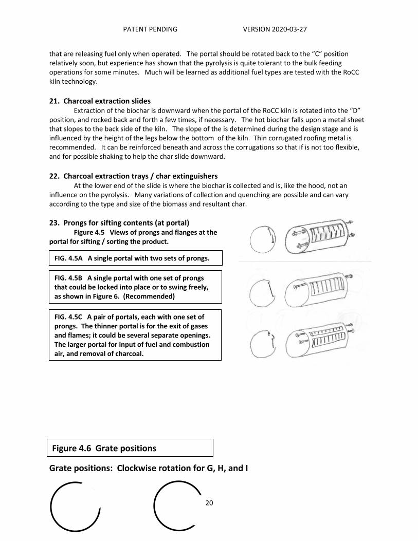
23. Prongs for sifting contents (at portal) Figure 4.5 Views of prongs and flanges at the portal for sifting / sorting the product.
Grate positions: Clockwise rotation for G, H, and I
FIG. 4.5B A single portal with one set of prongs that could be locked into place or to swing freely, as shown in Figure 6. (Recommended)
FIG. 4.5A A single portal with two sets of prongs.
FIG. 4.5C A pair of portals, each with one set of prongs. The thinner portal is for the exit of gases and flames; it could be several separate openings. The larger portal for input of fuel and combustion air, and removal of charcoal.
Figure 4.6 Grate positions
PATENT PENDING VERSION 2020-03-27
21
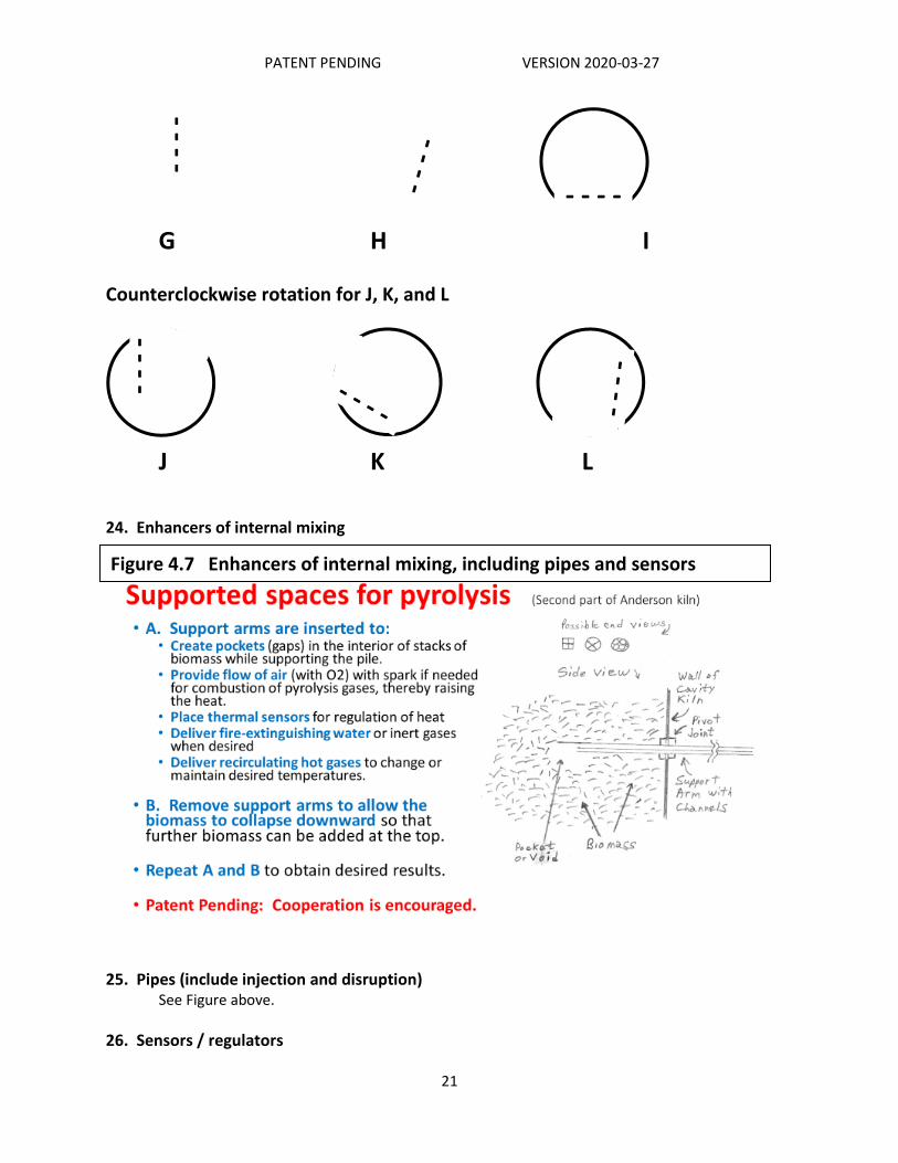
G H I Counterclockwise rotation for J, K, and L
J K L
24. Enhancers of internal mixing
25. Pipes (include injection and disruption) See Figure above.
26. Sensors / regulators
Figure 4.7 Enhancers of internal mixing, including pipes and sensors
- - - - -
- - - -
- - - -

PATENT PENDING VERSION 2020-03-27
22
See Figure 4.7 above. When RoCC kilns are large, such as the size of 20 ft shipping containers, the economic benefits of biochar production, thermal energy and potential extraction of chemicals justify the expenses of the larger size and of additional control features. Large units are likely to become quite automated, with numerous sensors that guide all operations a) for fuel input, b) pyrolysis temperatures at key locations, c) commands for rotations, d) emissions controls and e) the discharge and extinguishing of the biochar. When economic benefits are evident, the costs of sensors and regulators are relatively inexpensive. [Readers are invited to imagine the capabilities of a fully equipped large RoCC kiln when handling locally abundant biomass feedstock.]

PATENT PENDING VERSION 2020-03-27
23
Part Five: Specifics for Fabrication
Part Five has been restricted for the following reasons: 1. Part Four now has considerable details about the possible variations in each of the numerous components in RoCC pyrolytic kilns. There are far too many combinations to represent them well in a few specific suggestions for fabrication. 2. All prototypes constructed as of March 2020 are being improved. It is not possible to foresee all of the improvements, or even to know if some intended improvements might not work well. As an example, the most recent RoCC kiln is show in the Provisional Figures 5.1 to 5.4 on the next pages. The note are more about what not to do (or what will make it better) than about the actual details of fabrication and operations. 3. To provide specifics for fabrication at this time could lead to replication of known deficiencies by persons or entities unknown to Dr. Anderson, thereby possibly propagating the further replication of known deficiencies without recourse to contact all others to provide them with corrections.
4. Dr. Anderson will work with and assist fabricators of RoCC kilns who contact him about their interests and realistic intentions. To them he will provide the latest Specifics of Fabrication and encourage collaboration instead of isolated efforts. There are already several cases of this: a. Pennsylvania: 2-ft to 4-ft diameter b. California (Northern): 4-ft diameter c. Illinois: Home base of Dr. Anderson d. India (Odisha): 3-ft diameter e. Thailand (Northern): Special unit for in-field crop residues f. Canada (Ontario): (Not yet specified) 5. Companies or entities with special interest (such a size or biomass type) are encouraged to contact Dr. Anderson for his support of their interests and efforts. 6. There will eventually be many different models with separate specifications. Two designs are of note: a standard 55-gallon barrel; and a cylinder that is 3 – 4 ft in diameter. Contact Dr. Anderson for specific assistance about: Units with Axle: (Only one has been made thus far.) 55-gallon barrel-size RoCC Pyrolyzer with Axle Units with Rollers: 55-gallon barrel-size RoCC Pyrolyzer on rollers Larger 3 – 4’ Dia. and 5 – 10 ‘ Long RoCC units with Rollers Dr. Anderson can be reached at: [email protected] Office/Home phone: +1 309-452-7072 Mobile phone: +1 309-531-4434 (Chat and WhatsApp) Skype: paultlud

PATENT PENDING VERSION 2020-03-27
24
Provisional Figures 5.1 to 5.4 showing the RoCC pyrolyzer kiln, at Berkeley Olive Grove, near Oroville, California 28 Feb 2020 Figure 5.1 End View Notes: 1. The “X” frame for supporting the hood is not recommended. 2. The leaf blower, hose and draft inducer functioned, but will not be standard equipment. 3. The fuel loading shelf needs to be stronger. 4. The handles for rotation need to be longer. 5. The top of the hood should have a flat section. 6. Chimneys need to be at least two with 10-inch diameter. Figure 5.2 Diameter: 4 ft. Length: 5 ft. Material: Corrugated Steel Pipe. Frames: 2 x 2 inch hollow square pipe. Technical drawings are being prepared.

PATENT PENDING VERSION 2020-03-27
25
Figure 5.3 In the main operating position (“C”), with the flames and emissions going to the chimneys. Figure 5.4 The prongs (locked in place) worked very well for separating the finished char from the logs.

PATENT PENDING VERSION 2020-03-27
26
Part Seven: Patent and Business Topics
7.1 Patent topics: (Especially this section is subject to changes)
The invention is now covered by patent pending status. My intentions (not yet obligations) include the following: a. I will not allow the patent to fall under the control of any person or entity that would “bury” or “prevent the use of” the invention. b. I intend to actively promote and disclose during 2020 the major features of the RoCC kiln to encourage widespread dissemination and usage. c. I retain all rights to my invention and expect to receive some financial and other benefits eventually, especially from others who would receive such benefits as might relate to the invention. d. I hope to earn (from further work, not from the patent rights) from consulting and any forms of direct involvement in business(es) such as the making and selling of RoCC kiln methods and devices. e. My primary intentions are for beneficial impacts for the climate and societies, especially the severely poor. f. I would appreciate assistance in any constructive manner to maximize the beneficial impacts of this invention.
7.2 Business comments and options
Part Eight and Beyond 8.1 More to Come? (Certainly!!) NOTE: Yes, there is considerably more that can be written. More is already in the pipeline, especially as associated with active use of the RoCC kilns. But that will take time and will benefit for the experience of additional users. YOU are invited to contribute comments. Combined experiences will provide corrections and refinements of the initial draft documents (all are with dates to help keep them organized). Please help generate additional documentation.

PATENT PENDING VERSION 2020-03-27
27
Appendices Note: Expected documents that will include: References for further reading Fuel issues Experiences by early innovators Reports from test results Comments
Appendix A: Comparison of Flame Cap and RoCC technologies (A 20-slide PowerPoint presentation is prepared. If not attached to this version of this RoCC booklet, please go to www.woodgas.com/resources or contact the author.)
Appendix B: Issues about Carbon Dioxide Removal (CDR): (Revision in progress. Some
aspects are stated better in Section 2.1))
The Climate crisis problem (Others have and will write more than is summarized here.) The world’s societies are challenged by so many issues including economic wellbeing, health, over-population, food, water, governance, justice, wastefulness, and environmental problems of erosion, pollution, endangered species, deforestation and more. Mostly these are localized struggles However, a relative “latecomer” to the list of challenging problems is climate change that impacts everyone. There is not safe refuge from the disruption of the earth’s climate, the overheating of our planet. The worldwide climate crisis requires several realistic partial solutions, each contributing to a favorable total outcome. Hopefully, solutions about climate change can also bring solutions to some of the other issues. Management of carbon has impacts on our lives regarding energy, food, soil, atmosphere and climate. Centuries of carbon positive fossil fuel burning are to be totally stopped and replaced with increased carbon neutral renewable energy. In addition, there still remains the need to be carbon negative, to bring down the level of atmospheric CO2 via carbon dioxide removal (CDR), which is also called greenhouse gas removal (GGR) or negative emission technology (NET). Use of realistic, timely, and economically viable methods for CDR is gravely needed.
Seven major CDR approaches are summarized in Figure 1 and reinforced in Figure 2 that has biochar (BC) incorrectly combined with soil carbon sequestration (SCS). All seven could be needed if available soon enough. Some are at laboratory scales and not available. Some are or would be very expensive to accomplish at sufficient scale. Some compete for limited space and materials and need to be energetically managed. Each has its advocates and competes for scarce financial resources.

PATENT PENDING VERSION 2020-03-27
28
Figure 1: Major types of CDR (https://iopscience.iop.org/article/10.1088/1748-9326/aabf9b/meta#erlaabf9bf2)
OF EW AR DACCS BECCS BC&E SCS
Figure 2: Major types of CDR (Source: Carnegie Council) [Labels add by author.] >>>

PATENT PENDING VERSION 2020-03-27
29
Our focus is on the interface of Biochar (BC) and Bioenergy with Carbon Capture and Storage (BECCS). Our focus is on Biochar and Energy (BC&E), sometimes called Pyrolytic Carbon Capture and Storage (PyCCS, pronounced “pikes”) Why BC&E instead of BC or BECCS? The term biochar (BC) is all about charcoal and understates (actually, does not indicate at all) the energy value associated with the pyrolysis to create the biochar. That pyrolytic energy is expressed in the name “woodgas”, also known as “pyrolytic gases” or “the other biogas” that is not from anerobic digestion. BC&E expresses both sequestration and energy. [BC is
also well established to refer to “black carbon”, an important contributor to warming the atmosphere.]
BECCS is defined by its advocates to mean the burning of all the woodgas and charcoal into CO2 (for maximum energy extraction) and then trying to capture the CO2 and bury it in ways that might not be stable. Why pay to RE-capture the 50% of the CO2 that did not need to be created because it was already in the form of highly stable charcoal? Why struggle (and pay) for storage of unwanted CO2 when the stable carbon of biochar can be stored with advantages when appropriately placed into soil? And why bypass the advantages of woodgas that could be collected as useful chemicals and/or be cleanly combusted to be carbon neutral CO2 at no expense or as a valued replacement of fossil fuels. [We note that BECCS that would use the CO2 to produce biofuels is not sequestering that CO2, although biofuels can replace fossil fuels to the extent their production does not create CO2 or incur unfavorable expense.] Figure 1 (above) reveals important overlaps between the “implementation options” regarding land-based creation of biomass (photosynthesis by forestry and agriculture) and its destiny to either decay on the land or have chemical breakdown by heat (pyrolysis, char-gasification, or “burning”).
Appendix C: Biomass supply: (Revision in progress. Some content Is better stated in Section 2.2)
The types and where carbon is located are important. Figure 3 (based on R. Houghton, 2007) shows one quantitaive representation of the global carbon cycle. The annual flux of carbon in photosynthesis is 120 gigatons, with a return of the same amount (but much from different biomass) by respiration (oxidation) and litterfall.
Figure 3: Quantified Carbon Cycle (Petagrams = Gigatons = Billions of tons.) https://www.globe.gov/do-globe/measurement-campaigns/past-projects/earth-as-a-system-projects/carbon-cycle

PATENT PENDING VERSION 2020-03-27
30
That carbon is equivalent to about 440 Gt of CO2 taken from the atmosphere per year, approximately ten times the world’s total annual emissions of CO2. Converted into (dry weight) biomass, that extracted carbon of photosynthesis becomes 240 Gt, with the other half of the weight being oxygen and hydrogen atoms. Although much of that biomass is unfortunately unavailable for human usage, a mere 10% is 24 Gt per year. The USA alone has between 1 and 1.5 billion tons (1 – 1.5 Gt) of available dry biomass each year without impact on food or fiber production. Within that amount, USA urban areas produce tens of millions of tons of woody biomass per year and pay for its disposal. With pyrolysis, we can retain much of that carbon. Renewable biomass has massive potential to remove CO2 and has an indispensable role in AR, BECCS, BC&E and SES. The two products of BC&E (pyrolysis of biomass) are: 1. Stable carbon (biochar). This is about 50% of the carbon in biomass, and it is therefore about 25% of the dry weight of biomass. One gigaton of dry biomass can yield about 250 million tons of biochar that represents a removal of over 750 million tons of atmospheric CO2. 2. Combustible gases (woodgas). The gases contain about 50% of the carbon and all of the hydrogen in dry biomass, combusting to become CO2 and H2O. The one gigaton of dry biomass example becomes 10 exajoules (EJ) (being 10 billion gigajoules or 2.7 million gigawatt-hours) of primary energy. [Source: http://nap.edu/25259 Negative Emissions Technologies and Reliable Sequestration: A Research Agenda (2019), page 137.] Solutions for the climate crisis must have large impacts, as in gigatons, even though we cannot visualize such quantities. Fortunately for the case for BC&E, here is a favorable situation in which the wide and relatively thin distribution of biomass can be an advantage so that all of that biochar and energy can be utilized (as much as possible) in local areas close to where the biomass is grown. One gigaton of dry biomass involves only one million locations around the world annually doing pyrolysis of 1000 tons of biomass (3 tons per day), providing locally about 30 GJ/day (8333 kW-h thermal) plus useful biochar for sequestration of 1.5 t carbon or 5 t CO2e.
Appendix D: Perception, Process and Advantages: D.1 Perception America (and much of the world) needs to recognize the value of renewable biomass. American politicians proclaim their advocacy of renewable energy and say “wind, solar and biofuels.” Period. Full stop. Never a mention of lowly wood and other biomass as renewable energy. Apparently, they do not realize that plant growth is nature’s way of storing energy of the sun. They do not recognize that biomass of plants already heats many homes, and could heat so many more, even whole apartment complexes, central heating districts, industrial boilers, etc. Heating consumes about 40% of America’s energy budget, including use of high-value electricity for simple heating. Combine the benefits of biomass for heat and for carbon sequestration. Yes, both are possible from the same biomass. The “trick” is called pyrolysis that can be stopped when the woodgas has been released and the biochar still remains. Of woody biomass, 70% of the energy is released as pyrolytic gases while 50% of the carbon atoms remain behind as stable carbon. It is time to utilize what nature has given us. Solid, dry biomass fuel could be a major assist to win the battle against climate change, and the key process is pyrolysis, expressed as Biochar & Energy (BC&E).

PATENT PENDING VERSION 2020-03-27
31
D.2 Process Human use of the natural process of pyrolysis is as old as cave-dwellers pulling a burning stick from a fire to make a cave-wall drawing or the collecting of glowing embers to transport to another hearth. Over the centuries, mankind has developed hundreds of ways to make charcoal, some even in sizeable quantities. Unfortunately, production of large quantities almost always means expensive stationary equipment that requires transport of the biomass. Production of small quantities of charcoal is illustrated by the modern (21st century) Top-Lit UpDraft (TLUD = “tee-lud”) micro-gasifier cookstoves, of which Paul Anderson is a leading “pyroneer”. TLUD stoves produce about 2 pounds (0.8 kg) of char per day of use. Not much, but when multiplied by 35,000 households as in West Bengal, India, that is 28 tons of char per day (being sold for over US$3000 per day to a maker of incense sticks). At least 250 million impoverished families could use these stoves, improved their lives, and cumulatively produce biochar the would be CDR of 1.3Gt CO2 per year. Also, in the small category are barrel-size TLUD pyrolyzers and “flame-cap” kilns (aka open cavity kilns), both with requirements for operator attention and with size limitations. The need for medium scale pyrolyzers led Dr. Anderson to his development of rotatable covered cavity (RoCC) kilns during July 2019 to January 2020. The RoCC technology of methods and devices are now with patent pending status.
D.3 Advantages 1. Simplicity, with few moving parts With options for technical / mechanical enhancement for utility 2. Attention to principles of pyrolysis To know where temperatures are high (in areas of flaming emissions where clean burning and heat capture are desired), and where they are not high (usually between 400 to 750 degrees C) in the pyrolysis zone and even cooler in the lower area of the cavity where the accumulating charcoal is protected, meaning that the metal does not need to be protected with thermal ceramics, etc. 3. Use of low-cost materials Including use of standard products from other industries, such as metal culverts. 4. Scalable No size limitations are expressed. Different sizes will serve different user needs, as suggested in this Table 1.
Appendix E: Sizes and Tasks
No size limitations are expressed. Different sizes will serve different user needs, as suggested in this Table E.1. Sizes and likely uses of RoCC kilns
Line no.
Diameter range and (likely lengths) (feet)
Likely users and uses
1 Under 2; (2 – 6) (ex: 55-gallon barrel)
Education, sales demonstrations, and initial small-scale scientific experimentation with distinctive feedstocks or additives.
2 2 – 4; (3 – 6) Manually operated residential units of convenience (dried tree and bush trimmings and personal biochar production)

PATENT PENDING VERSION 2020-03-27
32
3 3 – 8; (6 – 16) Serious farm and woodlot production of biochar with possible use of the heat for fuel drying, with the units still able to be mobile but often utilizing mechanical and electronic controls.
4 4 – 8; (10 – 25) Stationary locations where the heat extraction is valued (such as for heating a school or apartment complex), with organized delivery of fuel with specified characteristics (type, size, moisture content, etc.).
5 6 – 12; (12 – 40) Stationary locations at industrial sites or “district heating” projects, each with customized fuel feeding systems.
6 10 – 16; (16 – 52) [A railway tank car typically measures 10 ft (D) and 52 ft long. Over 100,000 tank cars in America must be scrapped or rebuilt to meet new safety standards by 2025.]
Mass disposal of excessive biomass such as tree trunks and literal mountains of biomass that threaten communities as in California and Australia. NOTE: Reduction and/or disposal of excessive biomass is already a business model, but it lacks appropriate, high volume, low-emission technology that is economically viable, such as pyrolytic kilns that prevent 50% of the carbon that trees have removed from the atmosphere from returning to the atmosphere. The value of carbon sequestration is only beginning to be appreciated by a world that is getting warmer. And the research about biochar as a soil amendment (and safe form of sequestration) is getting stronger every month.
7 Larger than 16 feet The possibility remains open.
[Note: Contact Paul Anderson for guidance for the various sizes. The Patent Pending protection extends to these units. Dr. Anderson requests to be informed about the units being fabricated and used. That is a good way to have his support and appropriate recognition for your efforts that might be making history or be replicating efforts already known to work well or not.]

PATENT PENDING VERSION 2020-03-27
33
Table E.2 Sizes of RoCC Char Makers (from the PowerPoint in Appendix A.)
Appendix F: Calculations and Projections: Calculations: Pyrolysis of 1.5 gigaton of dry biomass (yielding 1 Gt of CO2 carbon drawdown) could be accomplished by many different combinations of the previously mentioned sizes.
Example 1: A simple example based on one “average” value for only 1.5 million locations around the world annually doing pyrolysis of 1000 tons of biomass (3 tons per day), providing locally useful 30 GJ/day (8333 kW-h thermal) of energy plus 1.5 t of biochar for sequestration 5 t CO2e/day, that, added together, is 1 Gt CO2 sequestered per year. The wide and relatively thin distribution of biomass can be an advantage so that all of that biochar and energy can be utilized (as much as possible) in local areas close to where the biomass is grown.
Example 2: A simple example could be the following 3-way split with 0.5 Gt per size: A. BC&E cookstoves (aka TLUD micro-gasifier cookstoves) 500,000,000 kg total biomass. Used at rate of 5 kg/day/HH (household) becomes 100,000,000 HH doing daily cooking and producing 100,000,000 kg of biochar that is spread into local soils which represents 366,000 kg of CO2 sequestration.

PATENT PENDING VERSION 2020-03-27
34
Notes: 1. The TLUD cookstove technology exists, is tested very successfully in a pilot project with over 35,000 HH in West Bengal, India. the project earns money via carbon credits and income into each HH, a true form of women empowerment. The only missing component is an initial one-time subsidy of US$40 per stove (factory manufacturing cost, which can be lowered with volume). This should be done for the humanitarian value, including the creation of much employment, regardless of the climate change value. 2. There is a maximum of 500 million such households worldwide, so the maximum scale up is only 5 times the amounts in Example 2.A. However, more could be used when affluent societies will also desire to have micro-gasification cookstoves with more improvements yet to be developed for such households, including pellet fuel and fan-assisted forced draft. B. RoCC kilns with < 5 ft ( < 1.5 m ) diameter 500,000,000 kg total biomass. Used at rate of 100 kg per hour x 4 hours/day x 100 days/yr (= 40,000 kg per RoCC kiln) requires 1,250,000 kilns in use mainly for local biomass reduction and minor use of heat, creating at 20% yield (by wt.) the amount of 100,000,000 kg of biochar that is spread into local soils which represents 366,000,000 kg of CO2 sequestration. Note: 1. These units are not optimal for commercialization of the heat, so any shortfall in this size range might be eclipsed by success in larger units. See next. C. RoCC kilns with > 5 ft ( > 1.5 m ) diameter 500,000,000 kg = 500 kt of total biomass. Used at rate of 1 t per hour x 10 hours/day x 200 days/yr (= 2,000 tons per RoCC kiln) requires 250,000 kilns in use mainly for local BC&E heating projects, creating at 20% yield(by wt.) the amount of 100,000,000 kg of biochar that is spread into local soils which represents 366,000,000 kg of CO2 sequestration. Notes: 1. Special case would be if all biomass in this size category was done by the likely “workhorse” unit with 8 ft diameter with 20 ft length (See Column I in Table 1 above which is reproduced below.) Two scenarios with different amounts of usage (A) & (B) are given.
Table E.2, Column I Comments
7500-gallon 1000 ft3 28 m3 =~20 ft container
The basic cylinder can be Corrugated Steel Pipe (CSP)
8 x 20 ft 10 x 13 ft 12 x 9 ft
At 8 ft diameter, this is the largest width allowed on US highways without special permits. Mobile units can go to where there is seasonal biomass or specific burning seasons.
2.5 tons per hour
(A=2000 x Col I) If 8 hr/day x 250 day/yr = 5000 t/yr. X 100,000 kilns= 500 Mt/yr (B=7200 x Col I) If 20 hr/day x 360 day/yr = 18 Kt/yr. X 28,000 kilns = 500 Mt/yr
500 kg/hr [ 1.8 t ]
(A) 1000 t/yr/kiln (eq to 3660 t CO2/yr). If CDR = $10/t, then $36 K gross ROI. (B) 3600 t/yr/kiln (eq to 13 Kt CO2/yr). If CDR = $25/t, then $325 K gross ROI.
30 GJ 8 MW-h 28 M BTU
(A) 240 GJ/day = 60 K GJ/yr (B) 600 GJ/day = 216 K GJ/yr. A cluster of 5 kilns could deliver 1 M GJ = 1 EJ

PATENT PENDING VERSION 2020-03-27
35
2. Another special case would be to have BC&E replace coal at coal-fired power plants. The largest CSP currently in production is 18 ft diameter. 40 ft length is used to accept full length tree trunks (or equivalent biomass). Gross volume is 10,178 ft3 (288 m3 = 76 K gal.) The estimated input could be 25 K to 30 K tons per hour. In operation 24/7/365 = 61,320 x 25 kg = 1,533,000 kg = 1533 t/yr. Approx. 330 such RoCC kilns would utilize the 0.5 Gt of biomass. The power plant could have as many such units as need for its thermal requirements. One estimate is that 3 or 4 of these very large RoCC Kiln could provide enough heat to operate one former coal-powered plant of about 120 MW capacity for electricity. 25 GJ/hr = 7000 kW-hour Example 3: Variations on Example 2.