Embed Size (px)
Citation preview

1
STRUCTURAL ROBUSTNESS OF CONCRETE FLAT SLAB STRUCTURES 1
J. Sagaseta, N. Ulaeto, J. Russell 2
3
4
Synopsis: 5
Current building regulations for design against progressive collapse normally use prescriptive rules and risk-6
based qualitative scales which are insufficient to cover current needs in design. Structural robustness of concrete 7
flat slab structures is examined using different theoretical models to capture the dynamic behavior under 8
accidental events. In such extreme events, the large dynamic reactions at the connections could potentially lead 9
to punching and progressive collapse. Punching formulae based on load-deformation response relationships such 10
as the Critical Shear Crack Theory (CSCT) are particularly useful in dynamic situations. The Ductility-Centred 11
Robustness Assessment developed at Imperial College London is also used in this paper to derive simple design 12
formulae to assess punching of adjacent columns in the sudden column removal scenario which is commonly 13
adopted in practice. The approach can be extended to assess flat slab systems upon considering membrane 14
action in the slab and post-punching behavior in the connections. Analytical models for tensile membrane are 15
used in combination with the CSCT to demonstrate that the tying forces required in codes of practice cannot be 16
achieved without prior punching of the connections. It is also shown that numerical modelling of post-punching 17
is a promising tool to review detailing provisions for integrity reinforcement. 18
19
Keywords: Punching shear; structural integrity; robustness; progressive collapse; flat slabs; accidental actions. 20
21
22

2
Juan Sagaseta is a Lecturer at University of Surrey, Guildford, UK. He received his PhD from Imperial College 1
London, UK. His research interest include shear, punching shear, strut-and-tie modelling, analysis of structural 2
concrete under accidental actions and progressive collapse. 3
Nsikak W. Ulaeto is a PhD candidate at University of Surrey, Guildford, UK, where he also received his MSc. 4
His research interests include punching shear, post-punching, structural concrete under dynamic actions and 5
progressive collapse. 6
Justin Russell is a Research Fellow at University of Warwick, Coventry, UK. He received his PhD from 7
University of Nottingham, UK. His research interests include progressive collapse, concrete flat slabs and 8
dynamic analysis of FRP structures. 9

3
INTRODUCTION 1
Reinforced concrete flat slabs, especially the flat plate variation without drop panels and column capitals, are 2
commonly used in infrastructure and the construction industry due to their efficient span-depth ratio and 3
uniform soffit. The design of flat slabs at ultimate is mainly governed by the detailing of the slab-column 4
connection in order to provide sufficient punching shear and deformation capacity. Punching is a brittle type of 5
failure with almost no warning signs. The shear resistance at a column after punching can be very low unless 6
special considerations are made in design to mitigate this effect (e.g. integrity reinforcement). Therefore, 7
punching of a column can cause large redistribution of loads including an increase in shear and eccentricities 8
(moment transfer) at the adjacent columns due to the irregular residual spans. These effects worsen due to the 9
dynamic nature of the load redistribution leading to an amplification of the reactions and slab deflections from 10
the global response. 11
Local failure at one column can propagate horizontally to adjacent columns in the slab as reported by Hawkins 12
and Mitchell1 or Regan2; some examples of horizontal propagation collapses in underground car parking 13
structures have been reported by Fernández Ruiz et al.3. Horizontal propagation of failure can lead to the slab 14
falling onto the floor below introducing large additional demands in the column-slab connections due to 15
dynamic effects after the impact. This event can trigger the vertical progression of the collapse leading to a 16
disproportionate collapse to the original cause. Examples of vertical collapses with severe economic and social 17
consequences can be found in America (e.g. Skyline Plaza Complex in Virginia, USA, 1973), Asia (e.g. 18
Sampoong Department Store, South Korea, 1995) and Europe (e.g. Bluche underground car parking, 19
Switzerland, 1981). It is worth noting that there are also examples in which the vertical progressive collapse was 20
successfully arrested by the slab leading only to partial collapse of the structure (e.g. Pipers Row car park in 21
Wolverhampton, UK, 1997). This highlights the need to better understand the structural response of the system 22
subjected to local failure in order to avoid introducing rules for design against progressive collapse that are 23
unsafe or overly conservative. 24
The horizontal and vertical propagation of failure is highly dependent on the response of the column-slab 25
connections in terms of their load and deformation capacity. This response is influenced by dynamic effects and 26
the development of alternative load path mechanisms that could develop in the slab for small and large 27
deformations such as compressive and tensile membrane action respectively. This paper analyses these relevant 28
factors by means of simplified formulae based on theoretically sounded approaches used for punching and 29
alternative load path analysis. A key aspect considered in this work is the use of load-deformation based 30
formulae for punching which allow using energy balance principles to estimate the peak dynamic deformation. 31
In this context, the Critical Shear Crack Theory (CSCT) by Muttoni4-5 is used and extended to dynamic cases of 32
column removal situations which could be used in an alternative load path analysis for the design for structural 33
robustness. For the alternative load path approach, the Ductility-Centred Robustness Assessment (DRA) 34
developed by Izzudin et al.6-8 was adopted; this approach, which was originally derived for the assessment of 35
progressive collapse of multi-storey buildings, has been widely recognized and applied to real steel-framed 36
composite multi-storey buildings8 and more recently to flat slab concrete buildings9. This paper shows that 37
simple design formulae can be derived to assess punching at the adjacent connections after sudden column 38
removal in flat slab concrete buildings (Fig. 1(a)) based on the DRA and CSCT approaches. A case study is 39
shown of a real office building which has been previously analyzed by the authors (Olmati et al.10) using a more 40
complex dynamic nonlinear finite element time history analysis. The role of membrane action (compressive and 41
tensile) and post-punching response of the connection is also discussed based on analytical and numerical 42
modelling carried out in this work which has been validated using existing experimental data of isolated slab 43
tests. 44
DESIGN AGAINST PROGRESSIVE COLLAPSE 45
Structural robustness or integrity is commonly defined as the insensitivity of a structure to local failure. 46
Understanding the causes of progressive collapse in building structures is essential towards the development of 47
design methods for the assessment and improvement of structural robustness. The UK Building Regulations11-12 48
pioneered the inclusion of specific requirements against disproportionate collapse in codes of practice after the 49
Ronan Point collapse in 1968. These general regulations were refined and used to feed into material-specific 50
design codes; for concrete structures these were covered by BS 811013 in the UK and subsequently passed on to 51
some extent to Eurocode 214 in Europe. In the US, the design against progressive collapse is currently covered 52
by GSA15 and DoD16 guidelines and in less extent by ACI 31817 (section 7.13 and 13.3.8.5 for two-way slabs). 53
An extensive review in this field by Arup18 showed that there are four recognized methods to design for 54
structural robustness in general structures: (i) tying force provisions, (ii) alternative load path methods, (iii) key 55
element design and (iv) risk-based methods. 56

4
Tying force provisions are generally recommended for structures with low-risk of progressive collapse. 1
Eurocode 214 (section 9.10) defines a set of prescriptive detailing rules for those structures which are not 2
specifically designed to withstand accidental actions which aim at providing a suitable “tying system” as shown 3
in Fig. 1(c). Similarly, ACI 318 provides structural integrity requirements for detailing which is only intended to 4
provide “improved redundancy and ductility”17. According to Eurocode 2, the objective of the tying system is to 5
provide “alternative load paths”14 after local damage by means of different mechanisms. However, it has been 6
questioned over the years7,18-19 on whether the structure can achieve sufficient deformations to develop these 7
mechanisms as prescriptive rules do not explicitly check the ductility of neither the connections nor the system. 8
Moreover, the tying force requirements in Eurocode 2 were originally conceived for precast panel construction 9
under blast or extreme wind conditions, similar to that in the Ronan Point collapse, and it is questionable 10
whether these rules are directly applicable to other types of construction such as flat slabs under progressive 11
collapse conditions. Flat slabs provide enhanced continuity and alternative load paths due to two-way bending 12
and membrane actions20-22, however, they are prone to punching at small slab deflections. In this paper, it is 13
shown analytically that punching would occur prior to the formation of the tensile membrane action (TMA) 14
required by the tying system. 15
(a) (b) 16
(c) 17
Figure 1 – Internal column removal scenario in concrete flat slab building: (a) SDOF approximation, (b) 18
compatibility condition between vertical displacement and slab rotation and (c) tying approach. 19
Increasingly popular are the alternative load path methods6,15-16 for considering progressive collapse which offer 20
a quantitative and more performance-based type of analysis although several simplifications are generally 21
required. For example, scenario-independent approaches may be adopted (the hazard triggering local failure is 22
not considered) which requires caution as key factors can be overlooked. In flat slab construction, some 23
examples in which scenario-dependent approaches might need to be considered include fire or blast situations 24
due to the continuity and redundancy of the structure (e.g. uplift pressures in blast or restraint strains after 25
thermal gradients under high-temperature conditions). Otherwise, sudden column removal (scenario-26
independent) is a widely accepted approach15-16 which provides a standard dynamic test of structural robustness 27
which can cover different extreme events. There is a noticeable growing tendency in research and practice to 28
focus on energy based approaches as described by Izzudin et al.7 which look at the deformation energy (strain 29
energy) done by the external forces and can be also analysed as the flux of energy during the collapse 30
(Szyniszewski et al.23). 31

5
A limitation of the application of the alternative load path approach in concrete flat slab design is the general 1
lack of knowledge of the dynamic response (load and deformation capacity) of the column-slab connections. 2
Design formulae for punching shear have traditionally focused on load capacity only and therefore they can only 3
be used in load-centered alternative load path methods such as the simplified static modelling proposed by 4
DoD16. The main drawback in such methods is the need to define load dynamic amplification factors (��) which 5
is cumbersome7. A value of �� equal to 2 is normally adopted in design for concrete structures15-16 which 6
corresponds to a linear response without damping and therefore it provides overly conservative results. Test 7
results on concrete flat slabs by Qian et al.21, Russell et al.22 and dynamic FE analysis by Liu9 and Olmati et al.10 8
show consistent values of �� between 1.2 and 1.6 depending on the gravity load and extent of the damage in the 9
slab. The proposed simplified approach presented in this paper for assessing punching of adjacent columns 10
under column removal situations provides consistent values of �� to those described in the literature9-10,22. 11
If alternative load path analyses fail to demonstrate suitable capacity for the redistribution of loads, risk-based 12
methods and/or the key element design method can be adopted. In the UK, for buildings above fifteen-story 13
and/or of large occupancy (Class 3 buildings12), a systematic risk assessment is required which might include 14
the design of specific key elements or alternative load paths. The design of key elements (removal of which will 15
lead to the collapse) could be based on prescriptive loads such as12 or based on actual loads from hazard-specific 16
guidelines (e.g. DoD16). Significant work is being carried out currently on risk-based approaches as recognized 17
in a recent COST project24 and more emphasis is being made on probability-based approaches in which the 18
uncertainty of basic parameters is included in the analysis. For instance, a simplified reliability analysis was 19
proposed by Olmati et al.10 in which the magnitude of the gravity applied load is considered as a stochastic 20
variable; this is a relevant parameter affecting the dynamic response of the flat slab structure as discussed in the 21
following sections. 22
RESPONSE OF FLAT SLAB BUILDINGS UNDER ACCIDENTAL AC TIONS 23
Extreme events such as industrial accidents (e.g. vehicle impact, blast), unexpected local failure due to 24
overloading or poor design, extreme weather or fire can lead to significant local damage. Such damage can 25
include column failure, flexural failure of the slab, punching of the slab-column connection and spalling of 26
concrete. The latter can be relevant as the size of debris and impact in other areas in the structure might be 27
significant and could trigger progressive collapse due to overloading. It is worth noting that most of these events 28
have a strong dynamic component; even local shear failures from a non-dynamic source (e.g. punching around a 29
connection due to quasi-static loading) triggers a dynamic redistribution of loading due to the sudden loss of 30
strength. Most codes acknowledge that the design against all possible accidental scenarios is not feasible since 31
extreme events are normally unforeseen events and engineering judgement should prevail. However, the lack of 32
theoretical models looking at the local and global response makes it difficult for the designer to tackle some of 33
these issues. 34
Local vs. global response 35
The study of local damage is normally carried out for single structural elements as shown schematically in Fig. 36
2(a) for localized punching of a flat slab due to close-in detonation and impact. Analytical models exist to assess 37
local perforation in such cases which can be based on SDOF models and the CSCT for punching (e.g. Micallef 38
et al.25 and Sagaseta et al.26 for impact and blast cases respectively). Work by Micallef et al.25 showed that the 39
punching capacity increases with strain-rates as shown in Fig. 2(c) due to the increase in material strength with 40
loading rate (increased residual tensile strength and aggregate interlock action along the critical shear crack). In 41
cases of impulsive behavior as those shown in Fig. 2(a), punching may occur at a short time after the action, 42
while the deformations are small compared to the peak deflection. The global response of the slab in such cases 43
has been shown to have a negligible effect on the occurrence of punching which is primarily governed by the 44
large shear demand around the localized action25-26. Due to the continuity and monolithic nature of flat slab 45
systems, the interaction between local and global response is not straightforward and the development of hybrid 46
models (local-global) is useful for different types of loading with different load durations. 47
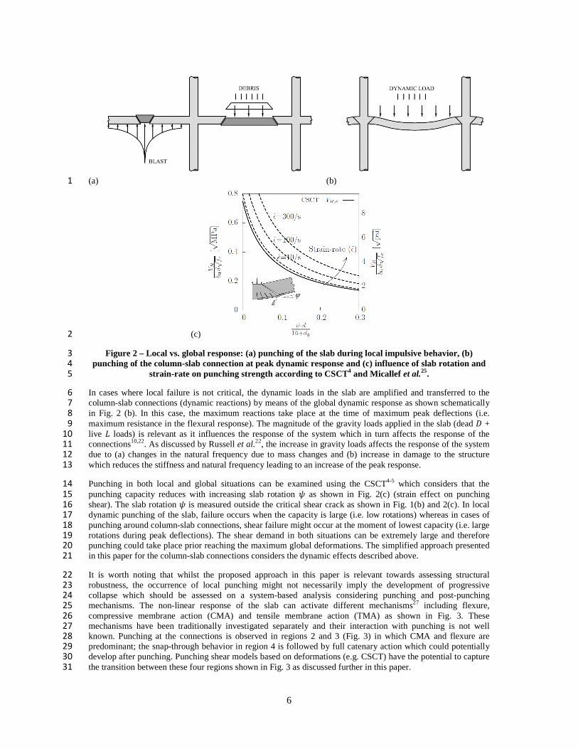
6
(a) (b) 1
(c) 2
Figure 2 – Local vs. global response: (a) punching of the slab during local impulsive behavior, (b) 3
punching of the column-slab connection at peak dynamic response and (c) influence of slab rotation and 4
strain-rate on punching strength according to CSCT4 and Micallef et al.25. 5
In cases where local failure is not critical, the dynamic loads in the slab are amplified and transferred to the 6
column-slab connections (dynamic reactions) by means of the global dynamic response as shown schematically 7
in Fig. 2 (b). In this case, the maximum reactions take place at the time of maximum peak deflections (i.e. 8
maximum resistance in the flexural response). The magnitude of the gravity loads applied in the slab (dead � + 9
live � loads) is relevant as it influences the response of the system which in turn affects the response of the 10
connections10,22. As discussed by Russell et al.22, the increase in gravity loads affects the response of the system 11
due to (a) changes in the natural frequency due to mass changes and (b) increase in damage to the structure 12
which reduces the stiffness and natural frequency leading to an increase of the peak response. 13
Punching in both local and global situations can be examined using the CSCT4-5 which considers that the 14
punching capacity reduces with increasing slab rotation � as shown in Fig. 2(c) (strain effect on punching 15
shear). The slab rotation � is measured outside the critical shear crack as shown in Fig. 1(b) and 2(c). In local 16
dynamic punching of the slab, failure occurs when the capacity is large (i.e. low rotations) whereas in cases of 17
punching around column-slab connections, shear failure might occur at the moment of lowest capacity (i.e. large 18
rotations during peak deflections). The shear demand in both situations can be extremely large and therefore 19
punching could take place prior reaching the maximum global deformations. The simplified approach presented 20
in this paper for the column-slab connections considers the dynamic effects described above. 21
It is worth noting that whilst the proposed approach in this paper is relevant towards assessing structural 22
robustness, the occurrence of local punching might not necessarily imply the development of progressive 23
collapse which should be assessed on a system-based analysis considering punching and post-punching 24
mechanisms. The non-linear response of the slab can activate different mechanisms27 including flexure, 25
compressive membrane action (CMA) and tensile membrane action (TMA) as shown in Fig. 3. These 26
mechanisms have been traditionally investigated separately and their interaction with punching is not well 27
known. Punching at the connections is observed in regions 2 and 3 (Fig. 3) in which CMA and flexure are 28
predominant; the snap-through behavior in region 4 is followed by full catenary action which could potentially 29
develop after punching. Punching shear models based on deformations (e.g. CSCT) have the potential to capture 30
the transition between these four regions shown in Fig. 3 as discussed further in this paper. 31

7
1
Figure 3 – Structural response of flat slab structures (adapted from Mitchell and Cook27). 2
ASSESSMENT OF PUNCHING OF ADJACENT COLUMNS AFTER COLUMN REMOVAL 3
Idealization of column damage 4
The sudden column removal scenario as proposed in codes of practice15-16 is probably the most common type of 5
design situation considered in the assessment of structural robustness. This approach studies the indirect 6
response of the building subject to an idealized theoretical structural damage with focus on the ability of the 7
structure to find alternative load paths. In this scenario, the selected support is removed instantaneously which 8
provides an upper bound in terms of the dynamic response. Whilst the concept and purpose behind this approach 9
is clear, the approach is not meant to cover all accidental actions as recognized by DoD16 since the nature of the 10
load causing the failure of the column is not considered. As reported by18 there is scarce information in the 11
literature regarding whether this is a realistic or overly conservative approach. The sudden column removal 12
neglects any residual strength and stiffness of the column after local failure, which is clearly not the case for 13
instance when the triggering event (local failure) is punching at the support as shown by testing on post-14
punching3,28-29. As shown by Keyvani et al.30, even in demolition tests in a post-tensioned flat slab building in 15
which a column was exploded intentionally to remove it completely, some residual resistance was observed at 16
the column due to residual deformations and some reinforcement bars surviving the explosion. 17
Demand-capacity ratio of adjacent column after sudden column removal 18
The assessment of punching of adjacent columns after sudden column removal is challenging due to the 19
uncertainty in the magnitude and role of the main parameters involved. Equation (1) shows the main factors 20
affecting the demand-capacity ratio (��) of the adjacent column after this event (�� >1 meaning that punching 21
will occur). The contribution of each parameter is described in this section. 22
DR�DR0�∆Vλd�∆M∆S (1)
Parameter ��� is the demand-capacity ratio of the connection being investigated for a specified loading prior to 23
the removal of an adjacent column, ∆� is the increase ratio of static shear force at the adjacent column after the 24
column removal, � is the dynamic load amplification factor, ∆ is the increase ratio of shear demand due to 25
moment transfer increase and ∆ is the decrease ratio of punching capacity due to the increase in span length 26
(i.e. increased slenderness). ��� is influenced by the gravity load considered and the design punching capacity 27
of the connection (��) considering nominal sizes of rebar and number of effective shear reinforcement 28
provided around the column. Regarding the gravity loads, in this work Eurocode 031 is used which gives 29
combination of actions for accidental loading which includes the quasi-permanent (D+0.3L) and frequent 30
(D+0.5L) combination cases in buildings with load categories A (domestic, residential) and B (office areas). 31
In terms of static behavior, it is widely assumed that in slabs with equal spans in both directions, the load carried 32
out by the removed column is transferred equally to the four closest adjacent columns leading to an increase in 33
the total shear at the adjacent columns of 25% (i.e. ∆�� 1.25). A linear finite element analysis (LFEA) of a flat 34
slab with infinite number of spans on either side and��/� � 1 (column size to effective depth �/� between 0.5 35
and 2 and column size to span �/� between 0.025 and 0.1) shows that ∆� can vary between 1.33 and 1.35 (Fig. 36
4(a)) which is due to the unbalanced load and unloading of the second row of columns (slab continuity). The 37

8
corner column adjacent to the removed one does not contribute significantly to this redistribution; the contour 1
diagrams in Fig. 4(a) show that the deformations around this column are similar to columns two spans from the 2
removed one. Parameter ∆� can increase significantly in buildings with irregular distribution of columns. For 3
instance if the span length in one direction is significantly shorter than in the other direction (e.g.��/� �1.5) 4
then the load carried out by the removed column can be transferred almost entirely to the closest columns (i.e. 5 ∆��1.5) as shown in Fig 4(a). In slabs with irregular bays with columns with different contributable areas, the 6
removal of highly demanded columns can result in values of ∆� closer to 2 as shown by Olmati et al.10. 7
Moreover, the increase in total shear in the column will be amplified due to dynamic effects by a factor � 8
which could vary depending on the gravity loads and column distribution. 9
(a) (b) 10
Figure 4 – Influence of column removal on: (a) static reaction in rectangular column layouts (contour 11
diagrams indicate the deflections in the slab for different cases of ��/��) and (b) distribution of shear 12
forces along control perimeter at 0.5d from column face for ��/�� � 1.5 according to shear field analysis. 13
Column removal results in an increase in the moment transfer in the adjacent columns which in turn will cause a 14
high concentration of shear forces in the control perimeter at the side of the removed column as shown in Fig. 15
4(b) obtained from a shear field analysis (thin lines represent the flow of principal directions of the shear stress 16
vectors and thick lines represent the magnitude of the shear per unit length along the control perimeter at 0.5� 17
from the columm face). Moment transfer is considered in design codes as an increase in shear stress demand by 18
means of increase factors based on a given shear distribution (Eurocode 2, ACI 318). Alternatively, other codes 19
such as Model Code 2010 use a reduced length of the control perimeter also known as “shear resisting control 20
perimeter” by means of a reduction factor ��. Therefore, parameter ∆ can be easily obtained using existing 21
design formulae in the different codes5,14,17. It is worth noting that due to the irregular residual spans, 22
recommended constant values for these factors normally do not apply and formulae based on obtained 23
eccentricities need to be used in such cases. Dynamic effects are likely to influence ∆ although the variations 24
observed in the shear stress demand factors are small with respect to those obtained from a static analysis with 25
residual spans (Olmati et al.10). 26
The influence of slenderness on punching has been investigated by Einpaul et al.32 showing that an increase of 27
slenderness in isolated tests leads to a decrease in stiffness of the load-rotation response of the slab and hence a 28
reduction of the punching capacity due to larger crack widths. This reduction in punching capacity ∆ is more 29
significant for slabs with shear reinforcement32 and it is currently not considered in Eurocode 2 and ACI 318 30
provisions. In a regular orthogonal column distribution, the slenderness of the critical span will double after the 31
loss of one column. Assuming a common office building in the UK with a slenderness �0.22��/� of around 5, 32
the column removal will result in a punching capacity reduction according to the CSCT of around 20% (∆�33 0.80) for a connection with shear reinforcement and heavily reinforced in flexure (e.g. �= 1.5%) and as low as 34
10% (∆� 0.9) if the connection has no shear reinforcement. In addition, dynamic amplification of the 35
deflections will result in a further reduction of the punching capacity due to wider cracks. As shown in next 36
section, this dynamic effect could be captured using the CSCT with an increased equivalent static slenderness or 37
“pseudo-static slenderness”. This is a similar analogy but opposite to that observed in local punching in 38
impulsive cases of impact and blast in which the small flexural deformations at punching could be viewed as a 39
“reduced effective slenderness” which is also referred to by in the literature25,33 as “reduced span”. 40
41

9
In this paper it is shown that for quasi-static column removal, the effect of increased slenderness on the flexural 1
response due to the increase in span lengths is captured accurately using Model Code 2010 formulae5. The 2
example shown in Fig. 5 (a) and (b) corresponds to a four-story office building described in Technical Report 3
6434 which is commonly referred to in flat slab design in the UK. Equation (2) is proposed in this work which is 4
based on the load-rotation relationship given by5 (Level of Approximation LoAII), considering the increase in 5
slenderness after the column removal at a shear force equal to �. Figure 5(c) shows that the predictions from 6
Eq. (2) are comparable with those obtained from a nonlinear finite element analysis (NLFEA) with quasi-static 7
loading by Olmati et al.10. Figure 5(c) also shows that the sudden change in slope in the load-rotation curve (Eq. 8
(2)) after column removal is captured correctly by increasing the slenderness from ���/� � 0.22��/� to 9 ���/� � 0.22��/� where ��is the approximate distance from the support axis to the point of zero radial bending 10
moment (subscripts 0 and 1 denote before and after column removal respectively) and ��and �� are the length 11
of the original and residual span respectively (�� � 6 m [19.7 ft] and �� �12m [39 ft] for the case considered). 12
� � 1.5 ����� � ��� �!"
# 0.37��&�
' , ∀ � � (2)
where according to Model Code 20105, � � 8�2*��/�2*� + 8,-�,�,� and *� is the width of the support strip 13
(normally equal to 1.5�� for internal columns with regular span layout) and -�,� is the eccentricity of the resultant 14
of the shear forces with respect to the centroid of the basic control perimeter in the direction investigated 15
(direction of residual span). For shear forces lower than �, Eq.(2) still applies by replacing terms (���/�) and 16
( # 0.37�) by (���/�) and respectively. A more refined analysis (LoAIII5) was carried out using a LFEA 17
showing very small differences in the values adopted for �� and �; in particular, parameter � was close to 8 18
using LoAII and III for the eccentricities obtained in the case study shown in Fig. 5. 19
(a) (b) 20
(c) 21
Figure 5 – Non-linear static response of column B2 after removal of column C2: (a) plan view of flat slab 22
structure, (b) shear reinforcement at B2 and (c) load-rotation response Eq.(2) and quasi-static NLFEA10. 23
24
25

10
Evaluating Eq.(1) using plausible values in design shows that �� can easily reach values near 0.8 for frequent 1
load combinations (D+0.5L). For example, the case study investigated by Olmati et al.10 (Fig. 5), for the load 2
combination (D+0.5L) resulted in the following: ��� = 0.3, ∆�= 1.7, ∆�= 1.15 and ∆�= 0.85which gives 3
�� = 0.5��; assuming a conservative dynamic factor of 2 will result on imminent punching (�� = 1.0) 4
whereas assuming more realistic values of �� (e.g. �� =1.3 from a refined dynamic analysis10) shows that 5
punching is not predicted to occur. This justifies the use of dynamic analysis to assess �� and ∆� in a more 6
rigorous and systematic manner. A dynamic nonlinear analysis is considered the most theoretically rigorous and 7
refined method to address this problem, however this approach is highly complex and computationally 8
demanding. A simplified approach is presented in the following section based on a nonlinear static pushover 9
analysis and simplified dynamic response based on energy balance as proposed by Izzudin et al.6-8. 10
Application of the Ductility-Centred Robustness Assessment (DRA): 11
The DRA proposed by Izzudin et al.6-8 is applied to flat slab structures in this work. This approach can be 12
applied to different levels of structural idealization. For instance, Liu9 used DRA and CSCT in their analysis of 13
a concrete flat slab building system by means of a macro numerical model. In this paper, the focus is on the 14
isolated response of the column-slab connection (sub-system) until punching failure; simplified analytical 15
equations are derived for this particular case. 16
As reported by Izzudin and Nethercot7 ductility-centered approaches such as the DRA allow consideration of 17
three critical factors for structural robustness namely, energy absorption capacity, redundancy and ductility 18
supply. Moreover this approach proposes the system pseudo-static capacity as a single measure of structural 19
robustness. The DRA consists of three steps: (i) determination of the nonlinear static response of the system 20
considered, (ii) dynamic assessment using a simplified approach based on energy balance and (iii) ductility 21
assessment of the connections by means of compatibility conditions between the system and the sub-system. In 22
this case, the flat slab system represents the bay of the removed column and the adjacent columns with the floors 23
above; this system can be modelled as a single degree of freedom SDOF system consisting of the vertical 24
deflection at the point of the removed column � as shown in Fig. 1(a). 25
The static response of the flat slab system is clearly nonlinear due to cracking of the concrete and yielding of the 26
reinforcement in the slab in the hogging and sagging regions (Fig. 3). Load-rotation relationship (Eq.2) can be 27
adopted in which the reactions and hence the gravity load is proportional to ��/� where � is the slab rotation in 28
the direction of the longest span outside the column region. The rotation of the slab varies along the span, from 29
zero at the column to a maximum value right outside the column region and then it remains constant and 30
gradually reduces to zero at mid-span. The exact distribution of slab rotation will vary depending on the loading 31
and amount of hogging and sagging reinforcement in the column and mid-span regions respectively due to 32
moment redistribution35. The compatibility condition between the system and sub-system degrees of freedom is 33
in this case simple to use � ≈ 1.5��� (Fig. 2(b)) which has been verified by the authors against experimental 34
and numerical results of continuous slabs with different hogging and sagging reinforcement ratios35. It is worth 35
noting that the value of the constant of proportionality of this relationship is not relevant in the dynamic study. It 36
can be concluded that the nonlinear static response of the system until punching will follow a parabolic 37
relationship � ∝ ��/� as shown in Fig. 3. The linear elastic response (region 1 in Fig. 3) is neglected as 38
commonly assumed in punching assessments in quasi-static loading; the loads causing punching normally result 39
in cracking and crushing of the concrete whilst yielding of the flexural reinforcement. This assumption holds 40
true for dynamic punching in column-slab connections governed by the global response of the structure. 41
The second step according to the DRA involves an energy balance calculation in order to obtain the peak 42
dynamic vertical deflection of the system (���). The total gravity load applied in the system (�) after the 43
column removal can be divided into two components, one is a static component which is resisted by the static 44
reactions after the column removal () and the other component is dynamic which is equal to the reaction of the 45
column removed which is applied suddenly into the system. As shown by Izzudin et al.7, the application of a 46
sudden load will introduce an amplification of the deflections so that the maximum dynamic response is 47
obtained when the kinetic energy of the system is zero and therefore the external work introduced by the gravity 48
loads equals the internal energy absorbed by the system. For instance, in a linear system shown in Fig. 6(a), if 49
the load ��� � is applied gradually the system will deflect � (external work introduced = internal strain energy 50
absorbed) whereas if the same load was applied suddenly the deflection would need to be ��� = ��� = 2� to 51
balance external work and internal energy (�� is the dynamic deflection amplification factor). If the system 52
follows a parabolic relationship � ∝ ��/� , it can be easily demonstrated that the deflection would need to be 53
��� = ��� = 2.15�. If the system follows a parabolic-plastic behavior as shown in Fig. 6(b), with a limit value 54
����, factor �� will be constant and equal to 2.15 for static gravity loads lower than ����,�� (e.g. load ��� �,) 55

11
whereas for static gravity loads higher than .���,�� (e.g. load .����,�) � will increase significantly in order to 1
achieve balance between internal strain energy and external work (shaded areas in Fig.6(b)). In Fig.6(b), .���,�� 2
is the static gravity load giving a dynamic deflection /��� which is equal to /���, where /��� is the value of the 3
deflection in the static response at which .��� is reached. The applied load versus maximum displacement 4
obtained from the energy balance approach is defined by Izzudin et al.7 as the “pseudo-static response” as it can 5
be obtained using static analysis. Figure 6(b) shows that for a given static gravity load .����, the peak deflection 6
can be obtained from the pseudo-static response and the corresponding amplified dynamic load (.��� �7
�.����), can be obtained from the nonlinear static response. 8
The pseudo-static response (.����, /���) can be written in terms of the static shear force around the column and 9
pseudo-static rotation (, ���) as shown in Eq. (3). Equation (3) was derived using the static response (, �) 10
from Eq. (2) and applying the energy based principles by multiplying � to the difference in slab rotation 11
(� # ��) to obtain ��� where �� is the slab rotation near the column investigated before the column removal. 12
Equation (3) is used subsequently in the ductility assessment in the last step in the DRA approach. 13
��� � 1.5 �� ���� � ��� �! 0"
# 0.37��&�
'�/� # �� # 1�2� " ��&�
'�/�1 , ∀ � � (3)
where � is the dynamic deflection amplification factor to the slab rotation near the column which is equal to 14
2.15 for ��� 2 ���� where ���� corresponds to the deflection /��� shown in Fig. 6(b). In the plastic region 15
(��� � ����), factor � is given by Eq.(4) which was also derived from energy balance (Fig. 6(b)): 16
� � ����/�3��������/� # 0.4�
���
�/�5�/� , ∀��� � ���� (4)
The pseudo-static response of the connection given by Eq.(3) follows a similar form to the static response 17
except for the introduction of coefficient � obtained from energy balance. In Eq.(3), term �����/�� can be 18
interpreted as an equivalent “pseudo-static slenderness” which accounts for dynamic amplification effects. The 19
negative term in Eq.(3) accounts for the fact that the dynamic amplification takes place from the load-rotation 20
point ��, ���. 21
22
(a) (b) 23
Figure 6 – Pseudo-static response according to simplified dynamic assessment6: (a) linear response and 24
(b) parabolic-plastic response proposed in this work. 25
The dynamic amplification factor of the load (�) can be obtained separately from the static and the 26
corresponding pseudo-static response. For a linear system, this approach gives � � 2 as expected, whereas for 27
a linear-plastic system this factor reduces significantly for loads near the plastic region. For the column-slab 28
connections under investigation, Eq.(2) and (3) are used to calculate � leading to Eq.(5) for loads below the 29
plastic region 30
� � 0.37 "� ' + 0� "1 # 0.37 � '�/� # �� # 1�
2 "� '�/�1
�/�
, � 6 6 ���/� (5)
where � is 2.15 for this region. For loads near the plastic region where � increases significantly according to 31
Eq.(4), the dynamic load factor is simply � � ���/ which decreases tending to 1 for large rotations assuming 32

12
that only flexural behavior is activated (i.e. without tensile membrane action). The reduction of � for ductile 1
systems has been recognized for some time and it has been considered by codes of practice16 for some types of 2
construction. It is worth noting that the activation of tensile membrane action for large deformations would 3
result in a sudden increase of � (Izzudin and Nethercot7), however in flat slabs, punching of the connection 4
would precede in such cases as shown in next section. The proposed Eq. (5) for punching gives values of � 5
between 1.67 and 1.2 depending on �/ which is a function of the column distribution. These values are 6
consistent with those obtained experimentally22 or numerically10 for flat slabs with similar levels of gravity 7
loads. For cases of sudden corner column removal, Qian and Li20 reported values of � between 1.13 and 1.23. 8
In order to carry out the ductility assessment in the third step of the DRA, the failure criterion in the CSCT is 9
applied. The proposed method to assess punching shown in Fig. 7 is described as follows: 10
- For a given static gravity load (.����), obtain the static shear before (�) and after ��� the column removal. 11
- Obtain the corresponding pseudo-static rotation � ! for � � from Eq.(3). 12
- For the obtained pseudo-static rotation, calculate the dynamic demand ��� � �� from Eq.(5) or using the 13
static response, and the dynamic capacity �,��� from the CSCT failure criterion4-5. 14
- Check whether the demand is lower than the capacity ��� 6 �,���, if so the procedure indicates there 15
should not be punching of the adjacent column under consideration. 16
17
Figure 7 – Proposed approach for punching assessment of sudden column removal based on the CSCT 18
and pseudo-static response from DRA. 19
As shown in Fig. 7 the philosophy behind the proposed approach is similar to punching for quasi-static loading 20
due to the use of the pseudo-static relationship. The proposed method is simple and it allows to check both load 21
and deformation capacity considering dynamic effects in a consistent manner. The dynamic factors are 22
automatically considered and refined predictions of the static response can be obtained by increasing the LoA 23
adopted. Strain-rate effects could be considered in the punching capacity and demand. For the punching shear 24
capacity, refining the failure criterion as a function of the strain-rate is possible25 as shown in Fig.2(c). For the 25
punching shear demand, a refined load-rotation response can be considered using material enhancement factors 26
dependent on the strain-rate5 as shown by Liu9 (FE model with shell elements) or SDOF models as shown by 27
Micallef et al.25. Furthermore, the proposed approach neglects shear redistribution around the perimeter (only 28
the radial direction along the residual span giving the maximum rotation is considered); as shown by Sagaseta et 29
al.36 if sufficient deformation capacity is provided in the direction of the maximum rotation more refined 30
predictions can be obtained using the CSCT considering the load-rotation in both orthogonal directions. The 31
simple proposed method and the different refinements described above can be written in a LoA format similar to 32
that proposed in Model Code 2010 so that it could be easily be applied in practice at different design stages. 33
Example of application of proposed method and comparison with dynamic NLFEA 34
The proposed method was applied to the case study of the office building shown in Fig.5 which was designed 35
for flexure and punching according to Eurocode 2. This structure was previously analyzed by the authors10 using 36
a more refined time history dynamic NLFEA for different gravity load combinations as part of a reliability 37
study. The span layout and main geometry are summarized in Fig. 5(a) and (b). In the dynamic NLFEA, the 38
gravity load was introduced gradually in the system and then column C2 was removed suddenly. Figure 8 shows 39
that the dynamic NLFEA predicted that punching would not occur in the adjacent column B2 for the frequent 40
load combination (D+0.5L) (�� �0.9) whereas punching was predicted to occur for the characteristic load 41
combination (D+L) (�� �1.1) which demonstrates that the structure is acceptable for accidental loading 42
according to Eurocode 031. The dynamic NLFEA shown in Fig. 8 shows that after the sudden column removal, a 43
slight unloading was predicted followed by a large amplification of the load and deformations following roughly 44

13
the nonlinear static response given by Eq.(2). As shown in Fig. 8, after reaching the peak deflections the 1
structure goes into the free vibration phase around a shear force equal to the static value (�) as expected. 2
Figure 8 shows that the proposed approach gives similar predictions of punching to the dynamic NLFEA with 3 ��� 6 �,��� (no punching) in the frequent load combination (Fig. 8(a)) and ��� � �,��� (punching) in the 4
characteristic load combination (Fig. 8(b)). The dynamic amplification factor of the load � obtained according 5
to Eq.(5) for the frequent combination (� = 508 kN [114 kip] and �=833 kN [187 kip]) was equal to 1.35 6
compared to 1.36 from the dynamic NLFEA10. For the frequent load combination (�), the ratio between the 7
maximum dynamic rotation and the static one (including rotation ��) is 1.76 compared to 1.80 obtained from 8
the dynamic NLFEA. The maximum vertical deflection of the system /��� predicted by the NLFEA had a 9
dynamic amplification factor of 1.82 after the column removal which is reasonably similar to the one derived in 10
this work from energy balance (� �2.15). Some differences between the results from the dynamic NLFEA and 11
the proposed method are expected as the latter approach does not take into account damping. The dynamic 12
amplification factors obtained in this work are also consistent to those obtained by Liu9 for a different prototype 13
building designed according to ACI 318 (4 span building with orthogonal column grid with � � ��= 6 m 14
[20ft]); in their analysis� obtained from their macro-model was 2.10 instead of 2.15 and � was 1.35 whereas 15
in this work a value of 1.25 is obtained using Eq.(5) for the column distribution considered �/� �1.3). 16
(a) (b) 17
Figure 8 – Application of proposed approach to case study and comparison with dynamic NLFEA10: (a) 18
frequent load combination (78 �0.9) and (b) characteristic load combination (78 �1.1). 19
CONTRIBUTION OF MEMBRANE ACTION 20
Compressive membrane action 21
It is well known that compressive membrane action CMA can result in a significant increase in strength and 22
stiffness of concrete flat slabs21,36 although its inclusion into theoretical models is not straightforward. Einpaul et 23
al.35 showed that CMA around the supports can develop in continuous flat slabs with low amounts of hogging 24
(negative) flexural reinforcement due to cracking and subsequent restraint dilatancy. Einpaul38 also showed that 25
this effect, which leads to a stiffer load-rotation response, can be taken into account by introducing a factor in 26
the parabolic load-rotation equation in Model Code 2010 which depends on the ratio between the cracking 27
moment and the flexural strength in the support strip. For column removal situations, the compressive 28
membrane action in the slab around the removed column can be significant (Keyvani et al.39) due to restraint 29
dilatancy after substantial cracking which is expected as the slab is not designed to resist sagging (positive) 30
moments in this region. This effect can cause a relative horizontal movement between the adjacent supports 31
pushing them away from each other. Keyvani et al.39 obtained compressive membrane forces at the adjacent 32
column of the order of 700 kN/m (48 kip/ft) for span lengths after column removal of �� �12 m (39 ft); the flat 33
plate studied by Olmati et al.10 shown in Fig. 5 predicted compressive membrane forces along line (2) at column 34
B2 of around 550 kN/m (37 kip/ft) for the frequent load combination and around 700 kN/m (48 kip/ft) near the 35
removed column. The increase in flexural capacity in such cases can be relevant and it can contribute 36
significantly in arresting progressive collapse. An example of the arrest of progressive collapse due to CMA of a 37
real building is shown by Keyvani et al.30 in which the column removal in a post-tensioned concrete flat slab 38
structure resisted progressive collapse with a relatively small permanent maximum vertical deflection /��� �39
��/300. Further research is needed on CMA and its modelling for general slab configurations. 40

14
Tensile membrane action and activation of tying forces 1
The development of tensile membrane action due to geometry nonlinearity after large deformations has often 2
been claimed as an effective defense mechanism to arrest progressive collapse (e.g. Hawkins and Mitchell1). In 3
fact, the tying force approach adopted in codes of practice is intended in many cases to provide resistance to 4
gravity loads relying solely on tensile membrane action. As discussed by7,18, an ideal efficient design for normal 5
load cases in which the suddenly applied gravity loads exceeds the plastic resistance of the system would require 6
a significant development of membrane action. This is shown schematically in Fig. 9(a) from7,18 by the shaded 7
areas representing the work done by the load and the internal energy required for stability of the system. In flat 8
slabs, lateral constraint can be provided by the continuity of the slab, however the development of tensile 9
membrane action might be preceded by punching around the supports. 10
(a) 11
(b) 12
Figure 9 – Tensile membrane action: (a) balance between work done and internal energy for gravity 13
static load above the plastic resistance6 and (b) calculation of membrane forces to resist gravity loads. 14
The limitation of tensile membrane action due to punching has not been well defined in the past as the 15
development of tensile membrane forces and punching has not been investigated in combination. Qian and Li20 16
showed experimentally that in order to develop significant tensile membrane action, mitigating actions need to 17
be put in place to avoid punching (e.g. column drops). In this section, the development of tensile membrane 18
forces is investigated using two widely accepted analytical membrane models developed by Park40 and Hawkins 19

15
and Mitchell1 both providing relatively similar results of membrane forces. These models are used in 1
combination with the CSCT since membrane action and punching capacity can therefore be written in terms of 2
the slab rotation near the column using the compatibility relationship� ≈ 1.5���. Park’s model is given by Eq. 3
(6) for a square plate with equal yield membrane forces of the reinforcement in each direction which is placed 4
over the whole area of the slab. 5
���� =
��
4∑ 1�� (−1)
��� �1 − ����ℎ ���
2����
��,�,�…
≈ 13.6 (6)
where is the uniformly distributed load in the slab and � is the tensile membrane force. Similarly, Hawkins 6
and Mitchell’s model is given by Equations (6) and (7) as a function of the strain along the membrane �: 7
� =�
4���√6� (7)
� =3��
2���√6� (8)
Both membrane models predict (from basic equilibrium considerations) that for larger slab rotations at the 8
boundaries, lower tensile membrane forces are required to balance the gravity loads (Fig. 9(b)). Conversely, if 9
the slab rotation at punching is small, the corresponding tensile membrane forces required will be significant 10
and potentially larger than the prescriptive tying forces used in design. A systematic analysis was carried out to 11
assess the minimum tensile forces that would need to be activated in the slab to resist gravity loads by means of 12
membrane action alone prior to punching. Different case studies were investigated for a regular column layout 13
changing the span length �� (from 4 m [13 ft] to 8 m [26 ft]), slab thickness (from 200 mm [8 in.] to 350 mm 14
[14 in.]), column size (from 200 mm [8 in.] to 400 mm [16 in.]), concrete strength (from 20 MPa [2900 psi] to 15
50 MPa [7250 psi]) and live loads (from 1 kN/m2 [21 psf] to 5 kN/m2 [105 psf]). The connections were designed 16
systematically for each case according to Eurocode 2 to obtain the required area of flexural and shear 17
reinforcement for the factored live load considered (1.35D+1.5L). For the amount of shear reinforcement 18
obtained in each case, the corresponding punching strength-rotation curve was obtained according to the failure 19
criterion of the CSCT as shown in Fig. 9(b). This curve was then used to obtain the maximum slab rotation that 20
a slab could ever achieve near the connection �� � for an accidental gravity load combination (frequent 21
combination D+0.5L). The rotation �� � was then used to assess the corresponding minimum tensile membrane 22
force required according to each membrane model as shown in Fig. 9(b). 23
Figure 9(b) shows the results from this analysis for a flat slab of span lengths equal to 6 m (20 ft), 250 mm (10 24
in.) thick, imposed loading of 4 kN/m2 (84 psf) and 400 mm (16 in.) square columns in which the minimum 25
tensile force obtained to resist the accidental load combination prior to punching was 680 kN/m (47 kip/ft) 26
according to Park’s model and 578 kN/m (40 kip/ft) according to Hawkins and Mitchell’s model. The 27
corresponding maximum rotation �� � was in this case 36 mRad. The tensile force obtained is significantly 28
larger than the tying forces required in UK provisions in the National Annex to Eurocode 2 (tying force varies in 29
this case from 43 kN/m (3 kip/ft) to 108 kN/m (7 kip/ft) depending on the number of stories); tying force 30
requirements in Eurocode 2 give even lower values to those in UK National Annex. For this case DoD 31
provisions for tying forces of flat slabs give a value near 200 kN/m (14 kip/ft) which is again significantly lower 32
than the membrane force needed to balance the gravity loads. 33
The parametric analysis showed that in the large majority of the cases considered punching would occur prior 34
the required level of rotation to form a pure tensile membrane with the required specified tying forces. Although 35
under a true column loss event other mechanisms may work to prevent progressive failure, the use of 36
prescriptive tie requirements may provide a false sense of security to a designer if they neglect to check ductility 37
capacity. It is apparent that further work is needed to investigate the tying force provisions in codes and its 38
applicability to flat slab systems. In particular, the introduction of ductility conditions would need to be 39
considered for different types of construction. With this respect, guidelines by DoD16 in its latest version (2009) 40
seem to go in this direction by giving rotation limits at the connections for frame structures; however for flat 41
slabs further work is needed. As discussed in next section, the assessment of ductility of the connections in flat 42
slabs is related to the post-punching response which is an under-researched field. 43
MODELLING POST-PUNCHING RESPONSE 44
The post-punching response of the connection can contribute significantly towards arresting progressive 45
collapse due to the residual capacity and ductility which could potentially allow the development of alternative 46
load paths such as tensile membrane action (Fig. 9(a)). Work on post-punching is scarce and it has traditionally 47
been focused on the residual capacity1-3,28. Hawkins and Mitchell1 or Melo and Regan28 demonstrated that the 48
tensile reinforcement at the top of the slab in the connection has a negligible contribution to the post-punching 49

16
residual strength. Tests by Fernández Ruiz et al.3 showed that slabs with tensile reinforcement alone could 1
develop post-punching strengths of around 30% of the punching strength whereas slabs with tensile 2
reinforcement and integrity reinforcement at the compression zone could have a residual strength of 70%; these 3
results are consistent to those given in the CIRIA report2. The early work by Regan led to the recommendation 4
which is also adopted in ACI 31817 detailing rules for structural integrity of using at least two reinforcement 5
bars in each direction passing through the column at the bottom of the slab. 6
The development of analytical models for post-punching is problematic as discussed by3,29 due to the large 7
number of parameters affecting the localized damage of the concrete around the reinforcement bars which often 8
requires several assumptions based on experimental evidence. The use of numerical models can provide 9
additional information regarding the deformation capacity of the connection after failure which can be critical in 10
the assessment of structural robustness. The development of numerical tools to model post-punching behavior 11
requires significant validation and verification against experimental data. Some modelling techniques of post-12
punching were presented by Keyvani et al.39 in which the flexural and integrity reinforcement was modelled 13
explicitly using connector (Cartesian–Cardan elements) between the slab and the assumed punching cone. Liu4 14
also used beam connector to model post-punching in the system model. A difficulty of such techniques is the 15
definition of the constitutive relationships used in the connectors based on pre-punching and post-punching 16
shear transfer mechanisms which are uncertain and difficult to assess individually. Alternative techniques 17
include the use of solid elements with discrete modelling of the reinforcement as presented in this section. 18
Tests PM4 and PM12 by Fernández Ruiz et al.3 without and with integrity reinforcement respectively were 19
modelled by the authors using LS-DYNA with solid elements as shown in Fig. 10. The FE models included only 20
one quarter of the test specimen due to symmetry. An explicit solver was adopted in the analysis with a 21
displacement control approach (gradual increase of vertical displacement 9 applied). The solid element 22
consisted of eight-noded hexahedral elements with a constant stress solid element formulation. The constitutive 23
model adopted for the concrete was the Winfrith plasticity concrete model with linear strain softening in tension 24
based on the fracture energy. The reinforcement was modelled explicitly as one dimensional beam elements 25
embedded in the concrete elements with a Lagrange solid constraint (perfect bond) which provided reasonable 26
predictions as the reinforcement of the specimens considered was well-anchored and the localized damaged of 27
the concrete near the reinforcement was taken into account directly in the model. Figures 10(b) and (c) show 28
that FE models captured the punching and post-punching strength of the tests considered and were also able to 29
capture the increase in post-punching capacity and stiffness due to the provision of integrity reinforcement. 30
Whilst complex, the modelling of post-punching using solid elements is a promising tool and could potentially 31
be used in the future to assess different detailing configurations proposed in design against progressive collapse. 32
(a) 33
(b) (c) 34
Figure 10 – Numerical modelling of post-punching using solid FE models: (a) mesh of one quarter of 35
specimen and deformations after punching, (b) and (c) comparison between experimental and numerical 36
predictions of residual strength for tests PM-4 and PM-12 respectively (tests by Fernández Ruiz et al.4). 37

17
CONCLUSIONS 1
Structural robustness of reinforced concrete flat slabs and their susceptibility to progressive collapse is highly 2
influenced by the structural performance of the column-slab connections. This paper presents a simplified 3
approach to assess punching of adjacent columns in a sudden column removal scenario, which is commonly 4
used in the assessment of structural robustness. The main conclusions from this work are: 5
1. Using load-deformation based formulae for punching (e.g. CSCT) is particularly useful for accidental 6
loading and dynamic situations, as shown in this work. Such approaches allow consideration of inertial 7
effects and apply energy based principles which can be used to assess dynamic punching cases 8
governed either by the local or global response. These situations are commonly found in progressive 9
collapse analyses of flat slab buildings for different triggering events (e.g. column damage, punching 10
around the connection, slab impacting from above and blast). 11
2. The sudden column removal scenario used in practice as a simple dynamic test of structural robustness 12
of the system, introduces a significant increase in the demand-capacity ratio of the adjacent columns 13
due to dynamic amplification of the reactions (demand) and reduction of the punching capacity due to 14
the dynamic amplification of the deformations (global response). It is shown that adopting a constant 15
dynamic amplification factor for the reactions equal to 2, as recommended in practice for concrete 16
structures, can lead to overly conservative results which justifies the need to carry out a more rigorous 17
dynamic assessment. 18
3. The proposed formulae for punching assessment under sudden column removal situations based on the 19
DRA and CSCT gives a simple but theoretically sounded solution which considers the main parameters 20
involved (i.e. dynamic effects on demand and capacity, increase in both moment transfer and 21
slenderness after column removal). The proposed pseudo-static relationship enables the introduction of 22
analogous concepts for quasi-static punching such as the definition of an increased pseudo-static 23
slenderness in the shear demand to rotation formula in Model Code 2010. The proposed method can 24
take into account strain-rate effects (in demand and capacity) and can also be formulated in a LoA 25
format so that it could easily be implemented in codes of practice. 26
4. The punching predictions for the case study presented using the proposed approach are consistent with 27
those obtained using a more refined dynamic NLFEA. The case study investigated confirms that 28
column removal is not always critical. The load dynamic amplification factor formula obtained from 29
energy balance considerations provides similar results to those observed experimentally and 30
numerically for flat slabs with similar levels of gravity loads. The proposed formula for λ� is only valid 31
for punching assessment of an individual connection and does not consider the development of tensile 32
membrane action (high-ductility). 33
5. The analysis carried out in this paper using different widely accepted tensile membrane models in 34
combination with the CSCT confirms that punching occurs prior the required level of slab rotation to 35
form a pure tensile membrane with the specified tying forces in codes of practice. Further work is 36
needed to confirm the potential development of tensile membrane action after punching in flat slabs, 37
which is challenging as it is highly influenced by detailing of the reinforcement in the slab crossing the 38
column. The numerical models presented in this work using solid FE models provide a promising tool 39
to address this problem, although they are complex as the flexural and integrity reinforcement needs to 40
be modelled explicitly. 41
6. The analytical and numerical tools presented in this work can be used in different alternative load path 42
analyses which are commonly used in the assessment of structural robustness. The use of the DRA and 43
the CSCT is promising in terms of assessing the arrest of progressive collapse of concrete flat slab 44
structures as both approaches are highly compatible. These approaches can potentially be used for more 45
realistic scenario-dependent analyses. 46
47
ACKNOWLEDGMENTS 48
The work is a continuation of a research project financially supported by the Engineering and Physical Sciences 49
Research Council EPSRC, Impact Acceleration Account (IAA) held by the University of Surrey (grant ref: 50
EP/K503939) linked with a previous project funded by EPSRC of the UK (grant ref: EP/K008153/1). The 51
authors would also like to acknowledge project collaborators at Arup in the UK (Tony Jones and David Cormie) 52
and EPFL in Switzerland (Aurelio Muttoni and Miguel Fernández Ruiz) for their feedback and technical 53
discussions on the topic. The valuable feedback from Bassam Izzudin from Imperial College London is also 54
acknowledged. 55

18
REFERENCES 1
1. Hawkins, N. M., and Mitchell, D., “Progressive Collapse of Flat Plate Structures”, ACI J. Proceedings, V. 76, 2
No. 7, 1979, pp. 775–808. 3
2. Regan, P. E., “Behaviour of Reinforced Concrete Flat Slabs”, Construction Industry Research and 4
Information Association (CIRIA), Report No. 89, 1981, 88 pp. 5
3. Fernández Ruiz, M.; Mirzaei, Y.; and Muttoni, A., “Post-punching Behavior of Flat Slabs”, ACI Structural 6
Journal, V. 110, No. 5, Sept. –Oct. 2013, pp. 812–801. 7
4. Muttoni, A., “Punching Shear Strength of Reinforced Concrete Slabs without Transverse Reinforcement”, 8
ACI Structural Journal, V. 105, No. 4, July–Aug. 2008, pp. 440–450. 9
5. Fédération internationale du béton, “fib Model Code for Concrete Structures 2010,” Ernst & Sohn, Berlin, 10
Germany, 2013, 434 pp. 11
6. Izzudin, B. A,; Vlassis, A. G.; Elghazouli, A. Y.; and Nethercot, D., “Progressive Collapse of Multi-storey 12
Buildings due to Sudden Column Loss - Part I: Simplified Assessment Framework”, Engineering Structures, V. 13
30, 2008, pp. 1308–1318. doi:10.1016/j.engstruct.2007.07.011 14
7. Izzudin, B. A; and Nethercot, D., “Design-Oriented Approaches for Progressive Collapse Assessment: Load-15
Factor vs Ductility-Centred Methods”, ASCE Structures Congress, Austin, 2009, pp. 800–1791. doi: 16
10.1061/41031(341)198 17
8. Vlassis, A. G.; Izzudin, B. A,; Elghazouli, A. Y.; and Nethercot, D., “Progressive Collapse of Multi-storey 18
Buildings due to Sudden Column Loss - Part II: Application”, Engineering Structures, V. 30, 2008, pp. 1424–19
1438. doi:10.1016/j.engstruct.2007.08.011 20
9. Liu, J., “Progressive Collapse Analysis of Older Reinforced Concrete Flat Plate Buildings Using Macro 21
Model”, PhD Thesis, University of Nevada, Las Vegas, 2014. 22
10. Olmati, P.; Sagaseta, J.; Cormie D.; and Jones, A. E. K., “Simplified Reliability Analysis of Punching in 23
Reinforced Concrete Flat Slab Buildings Under Accidental Actions”, Engineering Structures (under review). 24
11. Minister of Housing and Local Government, “The Building (Fifth Amendment) Regulations 1970”, (S.I. 25
1970, No. 109), Statutory Instruments of the UK, 1970. 26
12. Department of Communities and Local Government, “The Building Regulations 2010 - Structure: Approved 27
Document A”, HM Government, UK, 2010. 28
13. British Standards Institution (BSI), “BS 8110 Part 1: Structural use of concrete: Code of Practice for Design 29
and Construction”, BSI, 1997. 30
14. EN 1992-1-1:2004, “Design of Concrete Structures—Part 1: General Rules and Rules for Buildings”, 31
European Committee for Standardization (CEN), Brussels, Belgium, 2004, 225 pp. 32
15. General Services Administration (GSA), “Progressive Collapse Analysis and Design Guidelines for New 33
Federal Office Buildings and Major Modernization Projects”, Office of Chief Architects, Washington DC, 2000. 34
16. Department of Defense (DoD), “Design of Buildings to Resist Progressive Collapse (UFC 4-023-03)”, 35
Unified Facilities Criteria, Washington DC, 2009. 36
17. ACI Committee 318, “Building Code Requirements for Structural Concrete (ACI 318-14) and Commentary 37
(ACI 318R-14),” American Concrete Institute, Farmington Hills, MI, 2014, 519 pp. 38
18. Arup, “Review of International Research on Structural Robustness and Disproportionate Collapse”, 39
Department for Communities and Local Government, 2011, 198 pp. 40
19. Merola, R., “Ductility and Robustness of Concrete Structures Under Accidental and Malicious Load Cases”, 41
PhD Thesis, University of Birmingham, UK, 2009. 42
20. Qian, K.; and Li, B., “Experimental Study of Drop-Panel Effects on Response of Reinforced Concrete Flat 43
Slabs after Loss of Corner Column”, ACI Structural Journal, V. 110, No. 2, March–Apr. 2013, pp. 319–330. 44
21. Qian, K.; and Li, B., “Resilience of Flat Slab Structures in Different Phases of Progressive Collapse”, ACI 45
Structural Journal, V. 113, No. 3, May-June 2016, pp. 537–548. 46
22. Russell, J. M.; Owen, J. S.; Hajirasouliha, I., “Experimental Investigation on the Dynamic Response of RC 47
Flat Slabs After a Sudden Column Loss”, Engineering Structures, V. 99, 2015, pp. 28–41. 48

19
23. Szyniszewski, S. T.; Krauthammer, T.; and Yimk, H. C., “Energy Flow Based Progressive Collapse Studies 1
of Moment Resisting Steel Framed Buildings”, Final report to US army ERDC, CIPPS-TR-003-2008. Center for 2
Infrastructure Protection and Physical Security, University of Florida, 2009. 3
24. European Cooperation in the field of Scientific and Technical Research (COST), “Robustness of Structures 4
– Proceedings of the 1st Workshop”, ETH Zurich, Switzerland, 2008. 5
25. Micallef, K.; Sagaseta, J.; Fernández Ruiz, M.; and Muttoni, A., “Assessing Punching Shear Failure in 6
Reinforced Concrete Flat Slabs Subjected to Localized Impact Loading”, International Journal of Impact 7
Engineering, V. 71, 2014, pp. 17–33. 8
26. Sagaseta, J.; Olmati, P.; Micallef, K.; and Cormie, D., “Punching Shear Failure in Blast-loaded RC Slabs 9
and Panels”, Engineering Structures (under review) 10
27. Mitchell, D.; and Cook, W. D., “Preventing Progressive Collapse of Slab Structures”, Journal of Structural 11
Engineering ASCE, V.110, No.7, 1984, pp. 1513–1532. 12
28. Melo, G. S.; and Regan, P. E., “Post-Punching Resistance of Connections between Flat Slabs and Interior 13
Columns,” Magazine of Concrete Research, V. 50, No. 4, Dec. 1998, pp. 319–327. 14
29. Habibi, F., “Post-Punching Shear Response of Two-Way Slabs”, PhD Thesis, McGill University, Montreal, 15
Canada, 2012. 16
30. Keyvani, L.; and Sasani, M., ”Analytical and Experimental Evaluation of Progressive Collapse Resistance of 17
a Flat-Slab Posttensioned Parking Garage”, ASCE Journal of Structural Engineering, V. 141, No. 11, 2014. 18
31. EN 1990:2002, “Eurocode – Basis of Structural Design” European Committee for Standardization (CEN), 19
Brussels, Belgium, 2002, 115 pp. 20
32. Einpaul, J.; Bujnak, J.; Fernández Ruiz, M.; and Muttoni, A., ”Study of Influence of Column Size and Slab 21
Slenderness on Punching Strength”, ACI Structural Journal, V. 113, No. 1, Jan. –Feb. 2016, pp. 135–145. doi: 22
10.14359/51687945 23
33. Delhomme, F.; Mommessin, M.; Mougin, J. P.; and Perrotin, P., “Simulation of a Block Impacting a 24
Reinforced Concrete Slab with a Finite Element Model and a Mass-spring System”, Engineering Structures, 25
V.29, No.11, 2007, pp. 2844–2852 26
34. Concrete Society, “Guide to the Design and Construction of Reinforced Concrete Flat Slabs”, Technical 27
Report, No. 64, 2007, 101 pp. 28
35. Einpaul, J.; Fernández Ruiz, M.; and Muttoni, A., “Influence of Moment Redistribution and Compressive 29
Membrane Action on Punching Strength of Flat Slabs”, Engineering Structures, V. 86, 2015, pp. 43–57. doi: 30
10.1016/j.engstruct.2014.12.032 31
36. Sagaseta, J.; Muttoni, A.; Fernández Ruiz, M.; and Tassinari, L., ” Non-axis-symmetrical Punching Shear 32
Around Internal Columns of RC Slabs Without Transverse Reinforcement”, Magazine of Concrete Research, 33
V.63, No.6, 2011, pp. 441-457. doi: 10.1680/macr.10.00098 34
37. Collings, D.; and Sagaseta, J., ”A Review of Arching and Compressive Membrane Action in Concrete 35
Bridges”, Proceedings of the Institution of Civil Engineers – Bridge Engineering, 2015. 10.1680/bren.14.00039 36
38. Einpaul, J., ”Punching Strength of Continuous Slabs”, PhD Thesis, EPFL, No. 6928, Lausanne, Switzerland, 37
2016, 178 pp. 38
39. Keyvani, L.; Sasani, M.; and Mirzaei, Y., “Compressive Membrane Action in Progressive Collapse 39
Resistance of RC Flat Plates”, Engineering Structures, V. 59, 2014, pp. 554–564. 40
40. Parke, R., “Tensile Membrane Behaviour of Uniformly Loaded Rectangular Reinforced Concrete Slabs with 41
Fully Restraint Edges”, Magazine of Concrete Research, V. 16, No. 46, 1964, pp. 39–44. 42


![EC2 - Concrete Centre [Flat Slabs - 2007]](https://img.pdfslide.us/doc/110x75/551350094a7959b1478b45dc/ec2-concrete-centre-flat-slabs-2007.jpg)