Embed Size (px)
Citation preview

ROBUSTNESS COMPARISON OF DIGITAL IMAGE
WATERMARKING TECHNIQUE
Ling Cao
BSc Computer Information Systems
May 2005

2
Submitted by Ling Cao
COPYRIGHT
Attention is drawn to the fact that copyright of this thesis rests with its author. The
Intellectual Property Rights of the products produced as part of the project belong to
the University of Bath (see http://www.bath.ac.uk/ordinances/#intelprop).
This copy of the thesis has been supplied on condition that anyone who consults it is
understood to recognize that its copyright rests with its author and that no quotation
from the thesis and no information derived from it may be published without the prior
written consent of the author.
Declaration
This dissertation is submitted to the University of Bath in accordance with the
requirements of the degree of Batchelor of Science in the Department of Computer
Science. No portion of the work in this dissertation has been submitted in support of
an application for any other degree or qualification of this or any other university or
institution of learning. Except where specifically acknowledged, it is the work of the
author.
Signed Declaration
_______________________________________________________
This thesis may be made available for consultation within the University
Library and may be photocopied or lent to other libraries for the purposes
of consultation.
Signed Declaration
_______________________________________________________

3
ABSTRACT
The robustness of a watermark attracts a great deal of attention in digital
watermarking technique development. This type of watermark holds the majority of
demands for many watermarking applications. The extensive potential of digital
watermarking is absorbing. This project was concerned with the watermark
technologies applied to digital images. The project started with the very basic
terminology of watermark specification and selected a few typical watermark
methodologies in each principal domain. The investigation approach carried out some
classic watermark techniques from the literature survey. Whilst, we applied those
techniques to several original works and then evaluated the robustness and additional
important properties after the watermarked images were attacked by various image
distortion operations. The objectives of this study were based on applying some
reprehensive watermarking theories into our own practice in order to explore more
interests and obtain better and deeper understanding in this technique discipline.

4
Acknowledgements
I would like to thank Dr. Russell Bradford for his help and advice during this
project, and for providing me many papers and materials. I also would like to thank
my boyfriend Jason, who always gives me a lot of support. My parents, Lucy and
Amy for their constantly warmly cheering me up, brought me lots of encourages and
kept me making great efforts on my project.

5
CONTENTS
1 INTRODUCTION ......................................................................................................... 8
1.1 THREAT....................................................................................................................... 8
1.2 MOTIVATION ............................................................................................................... 9
1.3 REPORT STRUCTURE................................................................................................... 9
2 LITERATURE SURVEY............................................................................................ 10
2.1 BACKGROUND .......................................................................................................... 10
2.2 DIGITAL WATERMARK FORMULATION.......................................................................11
2.3 TERMINOLOGY OF DIGITAL WATERMARK ................................................................ 12
2.3.1 Steganography .................................................................................................. 12
2.3.2 Information Hiding........................................................................................... 12
2.3.3 Perceptive and Unperceptive Watermark.......................................................... 12
2.3.4 Blind watermark and non-blind watermark...................................................... 13
2.3.5 Contents of watermark message ....................................................................... 13
2.4 WATERMARK DOMAINS ............................................................................................ 13
2.4.1 Spatial domain .................................................................................................. 13
2.4.2 Discrete Cosine Transform (DCT) domain....................................................... 14
2.4.3 Discrete Wavelet Transform (DWT) domain.................................................... 15
2.5 THE ISSUES OF EXISTING WORKS .............................................................................. 15
2.6 CONCLUSION ............................................................................................................ 18
3 ELEMENTARY DESIGN........................................................................................... 19
3.1 INTRODUCTION ......................................................................................................... 19
3.2 OBJECTIVES .............................................................................................................. 19
3.3 REQUIREMENTS SPECIFICATION ............................................................................... 19
3.3.1 Hardware Configurations ..................................................................................... 19
3.3.2 Software Configurations....................................................................................... 19
3.3.3 Compatibility........................................................................................................ 19
3.3.4 Support Resources................................................................................................ 20
3.4 IMAGE WATERMARK TECHNIQUE REQUIREMENTS .................................................. 20
3.4.1 Perceptibility ........................................................................................................ 21
3.4.2 Robustness............................................................................................................ 21
3.4.3 Peak Signal Noise ratio (PSNR)........................................................................... 21
3.4.4 Use of keys ........................................................................................................... 22
3.4.5 Capacity and complexity ...................................................................................... 23
4 DETAILED DESIGN AND IMPLEMENTATION................................................. 25
4.1 INTRODUCTION ......................................................................................................... 25
4.2 PROGRAMMING TOOL............................................................................................... 25
4.3 IMAGE AND WATERMARK SELECTIONS .................................................................... 26
4.5 MESSAGE ENCODING................................................................................................ 27
6
4.6 METHOD OF CHOICE....................................................................................................... 28
4.6.1 Method 1: Least Signification Bit ........................................................................ 28
4.6.2 Method 2: Comparison - Based Techniques in Spatial Domain........................... 29
4.6.3 Method 3 Threshold-based of Mid-band in DCT Coefficients............................. 31
4.6.4 Method 4: Correlation-base of DWT method....................................................... 32
4.7 TESTING PLAN .......................................................................................................... 34
5 ATTACK WATERMARK......................................................................................... 36
5.1 ESSENTIALITY .......................................................................................................... 36
5.2 CLASSIFICATIONS OF THE ATTACKS PROCESS........................................................... 36
5.3 ATTACK TOOL – CHECKMARK .................................................................................. 37
6 WATERMARK DETECTION ................................................................................. 39
6.1 EXPERIMENTAL RESULTS ........................................................................................ 39
6.1.1 LSB substitution results........................................................................................ 40
6.1.2 Correlation-based method in spatial domain results............................................. 41
6.1.3 Threshold-based technique of Mid-Band DCT Coefficients results..................... 43
6.1.4 Correlation-based of DWT method results........................................................... 44
6.1.5 Peak Signal-to noise ratio (PSNR) Comparison results ....................................... 47
6.1.6 Complexity Comparison results ........................................................................... 47
6.1.7 Geometry transformation results .......................................................................... 47
6.2 CHECKMARK DETECTED RESULTS: ........................................................................... 48
6.3 SYNTHETICALLY EVALUATION ................................................................................. 48
7 CONCLUSION ............................................................................................................ 50
7.1 CONCLUSION ............................................................................................................ 50
7.2 FUTURE WORK ......................................................................................................... 51
7.3 LEARNING................................................................................................................. 51
8 BIBLIOGRAPHY........................................................................................................ 52
9 APPENDIX A ............................................................................................................... 55
APPENDIX B......................................................................................................................... 80

7
List of Figures
FIGURE 2.1 WATERMARK EMBED PROCESS........................................................................11
FIGURE 2.2 WATERMARK EXTRACTION PROCESS ..............................................................11
FIGURE 2.3 WATERMARK DETECTION PROCESS .................................................................11
FIGURE 2.4A ORIGINAL IMAGE ............................................................................................ 16
FIGURE 2.4B WATERMARKED IMAGE................................................................................... 16
FIGURE 4.1 THREE LEVEL WAVELET DECOMPOSITION ....................................................... 33
FIGURE 5.1 COMPARING ORIGINAL AND RECOVERED WATERMARK AFTER JPG
COMPRESSION ATTACKS ................................................................................ 38
FIGURE 6.1A WATERMARKED IMAGE................................................................................... 40
FIGURE 6.1B RECOVERED WATERMARK .............................................................................. 40
FIGURE 6.2 EXAMPLES RECOVERED ATTACKED LSB SUBSTITUTION RESULTS .................. 41
FIGURE 6.3 WATERMARKED IMAGE AND IDEAL RECOVERED WATERMARK....................... 41
FIGURE 6.4 RECOVER WATERMARK FROM GRAY SCALE MANIPULATIONS ATTACKS......... 42
FIGURE 6.5 WATERMARKED IMAGE AND IDEAL RECOVERED WATERMARKS
OF THRESHOLD-BASED DCT MID-BAND COEFFICIENTS................................. 43
FIGURE 6.6 EXAMPLES OF RECOVERED WATERMARK COMPARISON OF
THRESHOLD-BASED MID-BAND DCT COEFFICIENTS...................................... 44
FIGURE 6.7 WATERMARKED IMAGE AND IDEAL RECOVERED WATERMARK
MESSAGES OF DWT METHOD ........................................................................ 45
FIGURE 6.8 WAVELET DOMAIN DECOMPOSITION LEVEL 2 RECOVERED
WATERMARK AFTER ATTACKS ........................................................................ 46
List of Tables
TABLE 2.1 LUMINANCE QUANTIZATION MATRIX USED IN JPEG ...................................... 15
TABLE 3.1 SUMMARY OF POSSIBLE PERCEPTIBILITY ASSURANCE LEVELS .................... 21
TABLE 3.2 BASIC ROBUSTNESS REQUIREMENTS ............................................................ 23

8
1 Introduction
Digital watermarking has been developed since 1979, but it did not gain a large
international interest until 1990[1]. The rapid increase of interest in watermarking
technique is most likely due to the increased concern over copyright protection of
content.
There are many advantages of using digital multimedia data, it is easy to create, edit,
reproduce and distribute; however, these advantages can facilitate unauthorized uses
as well, such as illegal copying and unapproved modification of the content.
Copyright is one of the biggest issues for content providers to protect their intellectual
properties.
Some graphic designers, publishers, and artists may suffer from their works being
copied; nonetheless they could not protect their ownership due to lack evidence to
correct piracy. This was one of the primary reasons why watermarking had been
invented. Nowadays more and more graphical images were generated by image
processing software. This means the images were translated into digital form. To
prevent copyright infringement, the digital watermarking demands a more
complicated technique. The theory of digital watermarking was similar to that of
traditional watermarking but with many more complicated techniques involved. In
addition, the purpose of digital watermarking was not as simple as traditional
watermarking. It had multiple purposes in many disciplines. Therefore, the potential
of digital watermarking was realized in growing applications and areas. Comparing
with inchoate techniques, current methods had become more intricate. At the early
stage, digital watermarking was only considered to be about hiding the information
inside original media resources, which we should call cryptography. Subsequently, we
began to consider about how securely, strongly and imperceptibly the information
could be hidden. Future investigation revolves around minimizing the damage done
when extracting the information from the watermark.
1.1 Threat
Since common embed and detect methods became well known, they were not only
understood by their authors but also by their attackers. The attackers could always
expose the weakness and discover the content of the original watermark message and
attempt to destroy it.

9
1.2 Motivation
If we see the threat from another viewpoint, they could be considered as the
motivation of developing good digital watermarking.More advanced embedding and
detection algorithms are proposed constantly. Previous watermarking technique have
also been improved and corrected by more watermark developer. Watermark
messages were protected securely and stealthily. Digital watermark became the
preferred choice for copyright protection, as a result of individual and organizational
feedback from their previous experience.
There are different types of digital watermark, such as fragile watermark, blind
watermark and etc. Hence, we can apply watermarking to a wider range of exercises.
Digital watermarking techniques can be applied to image, audio and video. This
project emphasizes the robust features of digital image watermarking. The evaluation
selects some representative methods from existing research and development. To
maintain an impartial and scientific manner, the testing images for each method were
identical. Similarly, the image distortion will be selected by using the same attack
method.
1.3 Report Structure
The dissertation started with a general introduction about background, history and
status quo of digital watermarking technique. In the second part of the report is a
literature search study that expounded the essential knowledge that will be utilized.
This part had summarized some common accessible watermark algorithms. The
following parts are the main body of the dissertation contained watermarking
technique study implementation and evaluation results. The third part is the
Elementary Design that was based on study of the literature survey to define an
approach and foundation to implementation. Detailed design and implementation is in
fourth part that expanded the elementary design into detailed description. Thereafter,
the fifth part contains the implementation design. The approach was that applied
selected methodology which is explained in detail. The sixth part described
watermark attacks based on watermark weakness and corresponding image distorted
assumptions and part seven was result analysis, which evaluated and analyzed not
also individual aspect but also overall performance after-attacked watermark results.
The final part concluded the study and further work.

10
2 Literature survey
2.1 Background
There was tremendous growth and development of World Wide Web and digital
products. The digital watermarking techniques tend to gain a great deal of attention
and interest. From the number of published journals, the duration of research and
development in the field of digital watermarking had not been very long. Rapidity
development of digital watermarking was significant, due to the interposition of the
large corporations and strong supported from US military and ministry of finance.
Since 1998, IEEE Image Processing, IEEE conference, IEEE magazines, IEEE
Transaction on and so on, had published a large number of monographs and
disquisitions about the study of digital watermarking. Massachusetts Institute of
Technology (MIT) media lab delegate a number of research institutes and enterprises
applied to the patent of digital watermarking. Many of the research institutes included
government departments, academic organizations (universities) and well-known
enterprises such as Massachusetts Institute of Technology, American copyright
workgroup, GMD National Research Centre for Information Technology, Minnesota
University, Cambridge University, University of Vigo, US military and ministry of
finance, Sony Corporation, IBM, NEC and Holland Philip Corporation.
The development of the digital format brought a host of benefits to the users, such as
efficiency and dynamic nature but it causes many thorny problems for the author of
the original work. The reason is that digital techniques had caused mass distribution
of multimedia content easier to achieve. No matter whether this behavior is intended
or unintentional, the aftereffects for the author can only be seen as tortuous. Digital
watermarking technique is considered as a promising countermeasure against this
issue. [7, Page 1]
Digital watermarking means use of the signal processing method to insert a piece of
digital format information into the original media resource. This technology provides
a high level of safety, because the location of embedded information is secret, and
neither the watermark algorithm nor the location of embedding is made public.
Generally, digital watermarks should be unperceivable. The digital watermarking can
only be extracted by the special detector and only if detected by special approach. The
content is inseparable from the watermarking. A digital watermark can be used to
provide complementary copyright marking functionality because it becomes an
integral part of the content.

11
2.2 Digital Watermark Formulation
The diagrams below show the basic theories about Digital watermark technique.
Figure 2.1 Watermark Embed Process
Figure 2.2 Watermark Extraction Process
Figure 2.3 Watermark Detection Process
There is a very simple and basic watermarking method, that is,
( )WIfII W ,+=
Function 2.1 A simple example for embed watermark
Where Iw denotes watermarked image, which should be considered identical by the
human observer. I denotes original image, f is the watermark algorithm, function f
Watermarked
Image, HM
Y/N Watermark
Detection
Original
watermark,M
User key
Secret Key
Watermarked
Image HM
Extraction
Method
Extracted
Watermark
Original
Image, H
Watermarked
Image, HM
Secret
key
Embed
Method
Watermark
message, W

12
may be arbitrary, but the robustness of the watermark algorithm depends on which
algorithm is chosen. [20, Page 15].
2.3 Terminology of Digital Watermark
In the literature review, there are numbers of items of pivotal watermark knowledge
which should be specified for the reader to understand. Hereby, before further
investigation of digital watermark techniques, those technologies are named and
explained to reduce the confusion for the un-professional reader and watermark
beginner.
Watermarking techniques have a very close relationship with some other techniques
such as steganography and information hiding, but these techniques are still different
from watermarking. These three fields have a great deal of overlap and share many
technical approaches. However, there are fundamental philosophical differences that
affect the requirements, and thus the design, of a technical solution. [6, Page3]
2.3.1 Steganography
Steganography is derived from Greek, and means “writing”. It is of more use in
watermarked images, which means the message is inserted into the work, which may
be perceptible, however, it has been inserted in a secret way; only the owner or
authorized user can decode the meaning of the message.
Digital watermarking has some additional aspects than steganography, for example
robustness. We can only use the different applications and requirements to distinguish
these three fields of technique, although in some cases they may very similar.
2.3.2 Information Hiding
Information hiding (data hiding) emphasizes making the information imperceptible or
keeping the existence of the information secret. Its topic is about maintaining
anonymity and keeping part of the database secret from authorized users.
2.3.3 Perceptive and Unperceptive Watermark
Unperceptive watermark has now become the majority and keystone preference to be
developed. A human observer can easily recognize a perceptive watermark (we call it
human vision system (HVS)). The unperceptive watermarking can only be visible by
computer detectors, which means the quality of the original image is least affected. [5,
page 1 literature review] In contrast, a perceptive watermark is easy to be recognized
but visual result of the original work will be regrettably affected. A perceptive
watermark can also be considered as a former technique of unperceptive

13
watermarking.
2.3.4 Robust watermark and Fragile Watermark
Robustness is the key feature of the digital watermark. The digital watermark
requires being robust which means it difficult or impossible to remove or separate
from original image. The robustness of the watermark strategy depends on how well
the malicious buyer is identified and how infrequently an honest buyer is wrongly
implicated. [9] The robustness can be tested by using different attacks. Applications of
this type of watermark are copyright protection (such as inserting the author and work
serial number and other relative information into the image).
Likewise, fragile watermark is a type of watermark that inserts information into the
original unreceptively. It is easy to destroy. When the watermarked image has been
changed, the watermark will be changed correspondingly so that we can know the
watermark has been change or tampered with.
2.3.4 Blind watermark and non-blind watermark
Blind watermarks that use blind detection embedding, the blind detection can operates
without any knowledge of the original, un-watermarked content. This is in contrast to
informed detection, which needs some knowledge of the original un-watermarked
work. This knowledge can take the form of the original work itself or some function
of the original work.
2.3.5 Contents of watermark message
The watermark can just be treated as a pure noise which is added into the host image.
Sometimes the watermark can be added as a noise but with other side information
such as the information of the owner, and some other watermarks can just be
considered as a second message that must be transmitted along with the watermark
message. All of this means that watermarking is a form of communication. This type
of watermarking is a communication-based model. The watermark embedder wishes
to communicate with the watermark receiver by using a watermark as a message. [6,
Page 47]
2.4 Watermark Domains
2.4.1 Spatial domain
The ideal is to directly insert a watermark in the pixel value when the image is in the
spatial domain. The robustness of this domain is weak for a robust watermark and it
has been proved by research and latest development [8]. The most widely used
algorithm in the spatial domain is – Least Signification Bit (LSB) technique, which is
the simplest method of inserting the watermark. As we know, in still images every
pixel of color contains three components, which are red, green and blue (R, G, B).

14
Assume there are 3-bytes for each pixel. Each color component has 1-bytes/8bits, in
which the intensity of that color can be specified on a scale from 0 to 255. [8]
2.4.2 Discrete Cosine Transform (DCT) domain
In this domain, watermark means transforming the spatial image into the frequency
domain and inserting the watermark information by changing the frequency
coefficient. Of course, the transform is not necessary the whole image. This involves
selecting the pixels to be modified based on the frequency of occurrence of that
particular pixel. The frequency domain can overcome the greatest disadvantage of
techniques operating in the spatial domain. The frequency domain watermark is less
susceptible compared with the spatial domain, the LSB technique can also be applied
in the frequency domain. The watermark normally applies to the lower frequency
within an image, as higher frequencies are usually lost when an image is compressed
or frequencies are considered to contain perceptually signification information.
Frequency-based techniques result in a watermark that is dispersed throughout the
image and are less susceptible to attack by cropping. [8]
Two-dimensional DCT transform is the most commonly used digital image
compression system – the core of the JPEG system. As shown in Table 2.1 JPEG
system needs to transform the image to YCbCr color space1 after compression. The
image will be divided into 8 x 8 block in each (Y, Cb,Cr) color channel. The next step
is processing each block by applying DCT transformation. For all the DCT
coefficients divide by some pre-defined quantization coefficients. The upper left value
(0,0) =16, is the base quantization factor of the DC terms of each 8 x 8 block. The
lower right value (7, 7) = 99 is the base quantization factor for the highest-frequency
terms. [6]
(u ,v) 0 1 2 3 4 5 6 7
0 16 11 10 16 24 40 51 61
1 12 12 14 19 26 58 60 55
2 14 13 16 24 40 57 69 56
3 14 17 22 29 51 87 80 62
4 18 22 37 56 68 109 103 77
5 24 35 55 64 81 104 113 92
6 49 64 78 87 103 121 120 101
7 72 92 92 98 112 100 103 99
1 The YCbCr color space is widely used for digital video. In this format, luminance information is stored as a
single component (Y), and chrominance information is stored as two color-difference components (Cb and Cr). Cb
represents the difference between the blue component and a reference value. Cr represents the difference between
the red component and a reference value.

15
Table 2.1 Luminance quantization matrix used in JPEG
In majority of images, the percentage of high frequency coefficient is small, the
coefficients are always 0. The human vision system is not sensitive to high frequency.
Therefore, we always adopt the thick quantification to high frequency coefficients.
Low energy in high frequency coefficient does not affect the degradation of image
quality of reconstructed image. The change quantification coefficient may change the
compression ratio. The quantification may damage the compression, so has the
blocking effect.
2.4.3 Discrete Wavelet Transform (DWT) domain
The wavelet domain method transforms both the image and watermark into the
discrete wavelet domain. This method uses a multi-resolution wavelet decomposition
of both the original image and the watermark. It is based on the Human Vision
System. When the image is decompose by wavelet transformation, its components are
separated into bands scale, much like the retina of the eye splits an image into several
components. The Discrete wavelet transform will allow the independent processing of
the resulting components much like the human eyes. The low –frequency components
have to be modified in order to embed the information in a reliable and robust way.
DWT has high robustness of the approach to JPG compression and additive noise and
linear filtering. [1]
Many other transforms had been also considered for digital watermark technique. For
example, the discrete Fourier transform (DFT), the Fast Fourier Transform (FFT) and
Fourier-Mellin transform and fractal transform.[26]
2.5 The issues of existing works
The early days of digital watermarking focused on hiding information techniques,
without considering the attack effect on the watermark. Thus early work can be
thought of as steganography, as in particular application in which a covert channel
between two parties is desired and tamper resistance may not be an issue compared
with the situation at present, if only the communicating parties are aware of the
channel [11]
Current researchers put their strong interests on robust watermark technique
development. Ingemar J. Cox et al are the founders of the digital watermarking
technique field. Cox first proposed that for a watermark to be robust, it should be
embedded in the significant components of an image. As Cox mentioned [10] in his
review, we can just consider the watermarking process to be viewed in this way:
There are two pieces of information combined together in such a way that they can be
detected independently and the detection for each piece of information is totally
16
different. One piece of information is the original resource or data such as a movie, a
song track, or a photograph, which can be detected by Human Vision System (HVS).
The other piece of information is the watermark, the secret part which can only be
detected by a specially designed watermark detector.
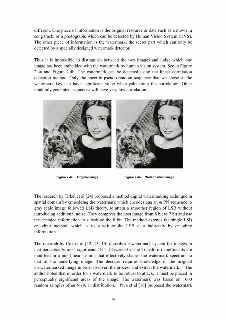
Thus it is impossible to distinguish between the two images and judge which one
image has been embedded with the watermark by human vision system. See in Figure
2.4a and Figure 2.4b. The watermark can be detected using the linear correlation
detection method. Only the specific pseudo-random sequence that we chose as the
watermark key can have significant value when calculating the correlation. Other
randomly generated sequences will have very low correlation.
Figure 2.4a Original Image Figure 2.4b Watermarked image
The research by Tirkel et al [24] proposed a method digital watermarking technique in
spatial domain by embedding the watermark which encodes qua an m PN sequence to
gray scale image followed LSB theory, to attain a smoother region of LSB without
introducing additional noise. They compress the host image from 8 bit to 7 bit and use
the encoded information to substitute the 8 bit. The method extends the single LSB
encoding method, which is to substitute the LSB data indirectly by encoding
information.
The research by Cox et al [12, 13, 10] describes a watermark system for images in
that perceptually most significant DCT (Discrete Cosine Transform) coefficients are
modified in a non-linear fashion that effectively shapes the watermark spectrum to
that of the underlying image. The decoder requires knowledge of the original
un-watermarked image in order to invert the process and extract the watermark. The
author noted that in order for a watermark to be robust to attack, it must be placed in
perceptually significant areas of the image. The watermark was based on 1000
random samples of an N (0, 1) distribution. Piva et al [16] proposed the watermark

17
technique by using DCT method to modify the mid-band frequency of the whole
image.
The research by Hsu and Wu [10, 23] describes a method in which the watermark is a
sequence of binary digits that are inserted into the mid-band frequencies of the 8 × 8
DCT coefficients. Some researchers compute the DCT by the whole image, and then
insert a real sequence watermark in the mid-band frequency. The advantage of
inserting the watermark in mid-band frequency is that it reduces the effect on the
human vision system from the inserted watermarking data. It can also avoid the loss
from the compression of the watermark.
Kutter et al [32] proposed the method to improved spread spectrum watermarking in
the spatial domain. This method exclusively works with the blue image component, in
RGB color space, which means the blue component has the maximum strength and
minimize visual affection. They also described how the preprocessing of the image
prior to watermark decoding could increased robustness, this watermark strategy is
applicable to any spread-spectrum spatial domain watermarking
In 1996, the research by Bender et al [21, 10] describes several possible watermarking
methods. In particular, “Patchwork” encodes a watermark by modifying a statistical
property of the image. The authors note that the difference between any pair of
randomly chosen pixels is Gaussian distributed with a mean of zero. This mean can be
shifted by selecting pairs of points and incrementing the intensity of one of the points
while decrementing the intensity of the other. The resulting watermark spectrum is
predominantly high frequency. However, the authors recognize the importance of
placing the watermark in perceptually significant regions and consequently modify
the approach so that pixel patches rather than individual pixels are modified, thereby
shaping the watermark noise to significant regions of the human visual system. While
the exposition is quite different from Rhoads [22], the two techniques are very similar
and it can be shown that the Patchwork decoder is effectively computing the
correlation between the image and a binary noise pattern
Liang et al [27] and Corvi et al [28] are the first authors that refer to the wavelet
domain technique for watermarking. They describe such an embedding strategy that
operates on the coefficients of a low- resolution approximation representation of the
host image. This approximation image can be derived in various ways. For instance,
use the wavelet decomposition method to compute three-level of host image, the
result approximate image is equivalent to the sub-band formed by DC coefficients of
a DCT on 8 x 8 image blocks. Liang et al [27] proposed that watermarking strategies
that operate in the general low-frequency sub-band without depending on any
particular feature of the wavelet decomposition. [26, page5]
Kundur [25] describes a method of embedding a binary map watermark into an image
by modifying the amplitude relationship of three transform domain coefficients from

18
distinct detail sub-bands of the same resolution level of the host image. Each selected
coefficient is sorted and the middle coefficient is quantized to encode either a 1 or a 0
bit.
These studies reveal the key issues that should be taken into account when
considering applications of digital watermarking technique. For instance, the types of
watermark is demanded may depend on what sorts of attack the image will be
distorted, which domain to apply it in, what algorithms to implement, the key to
encrypt the watermark message and the detection procedure.
Moreover, from studies showing those to be imperceptible, irremovable and to have
high information content are contradicting. For example, a more robust watermark
makes it either more perceptible or/and less informative. In a subjective view, the
perfect digital watermark algorithm should embed a great amount of the data and also
to deter any kinds of signal distortion, but these three properties cannot be achieved at
the same time. This fact does not have an impact on the implementation of these
properties because the applications are already emphasized particularly on one of
these properties in each case.
In addition, to measure the merit of a new watermark technique we need to compare it
with existing systems by our testing criteria. In general, the new system should show
an improvement in any one property, all else being equal. We can then say the new
system is worthwhile; at least it is important on that property on applications. [6,
Page37]
2.6 Conclusion
Numerous different watermarking techniques have been proposed in the literature
since digital watermarking technique naissance. Each technique can generally be
modified to proceed. Frankly, it would be impossible to compare all of them in
practice. Thereby, the techniques can be roughly divided into several categories which
depend on the way for the embedding process. None other than the typical
representatives in each category would be involved in the comparison study.

19
3 Elementary Design
3.1 Introduction
After literature experience, some typical watermark technique will be selected for
further investigation about robustness comparison. This section is the preparation for
implementation which provides all elementary requirements and objectives for the
investigation to obey and followed.
3.2 Objectives
� The investigation should provide at least four watermark techniques for
the robust watermark comparison use.
� Each selected watermark method must have complete embed and extract
algorithm in order to produce a watermarked image and recovered
watermark.
� Several image attacks must modify a watermarked image from each
method.
� The performance analysis must be provided for evaluation purposes.
� The project must be carried out by individual work of Ling Cao.
� The dissertation of project must be hand in May 16th with full
documentation which including the coding of the project in both soft
copy and hard copy presentation.
3.3 Requirements Specification
3.3.1 Hardware Configurations
The watermark programs will be developing based on PC or Laptop Windows
application with commonly used version.
3.3.2 Software Configurations
The watermark methods will be generated by using MATLAB version 7 or earlier
version with install the toolbox image processing toolbox and wavelet toolbox
applications installed.
3.3.3 Compatibility
Each program should be able to run in common versions of Windows and UNIX

20
environments.
3.3.4 Support Resources
� To search the information by using the Library loan, journal of computer graphic,
previous dissertations.
� Update the all information of the project by visiting the following website:
<http: www.cs.bath.ac.uk/~amb/CM30076>
� The essential mathematical theories knowledge: Spatial Watermarking techniques,
patchwork Algorithm, transformations, Discrete Fourier Transform, spectral
watermarks, etc.
� The essential programming language Skills: MATLAB
� The essential programming software: MATLAB version 7.0 with toolboxes.
� The programming language book: Digital Image Processing Using MATLAB,
Richard E. Woods, Rafael C.Gonzalez, Steven L.Eddins, ISBN 7-5053-9876-8
� The essential graphic software: Microsoft VISIO.
� Keep contact with project supervisor frequently. Hold regularly meeting with
project supervisor (twice a week), show the process of the project so far.
� The occasional meet other staff in the department when the supervisor is not
available or require other helps.
� Access the university facilities such as computer science lab and Online Libary.
3.4 Image Watermark Technique Requirements
Robust watermark is the preference of this research project. There are a few
requirements for watermark methodology that must be satisfied when the watermark
being considered as an ideal watermark creator. Any one certain methodology may
not fit each requirement but have outstanding performance in particular functions.
This issue is always adjustable as different applications request watermarks deliver
tremendous effects on particular performances rather than the overall performance.
Some application allows the watermark technique has weak performance at particular
feature which in low priority requirement. Sometimes the performance of low priority
requirement even can be ignored. For example, the preferred watermark may be the
fragile watermark to test whether or not the original watermark has been modified
without the authority permission.
To carry out a fair method for comparing robustness of watermark technique, there are
several general attributes that a good robustness watermark should possess. These
methods are as follows:

21
3.4.1 Perceptibility
Perceptibility should be bringing forward at first. The outdated watermark technique
in the very beginning will always have the perceptible watermark on the original
object. This result watermarked image should not have distinguishable different.
The more difficult task is providing metrics for perceptibility and robustness.
Petitcolas as well as others suggest the scheme listed below in Table 3.1 for the
evaluation of perceptibility [31]
Level of
Assurance
Criteria
Low - Peak Signal-to-Noise Ratio (PSNR)
- Slightly perceptible but not annoying
Moderate - Metric Based on perceptual model
- Not perceptible using mass market equipment
Moderate High - Not perceptible in comparison with original
under studio conditions
High - Survives evaluation by large panel of persons
under the strictest of conditions.
Table 3.1 Summary of Possible Perceptibility Assurance Levels [14]
3.4.2 Robustness
Watermark methodology is respected and can produce the robust watermark after
image distortions. This means that the watermark can be detected by using the
recovered algorithm with the corresponding key when needed. The robust watermark
should be readable and survive after majority of distortion attacks such as filtering,
lossy compression, noise adding and various geometrical transformations. Compared
with the original watermark message, extracted watermark from the attacked image
may look fuzzy, but still recognizable by human visual system (HVS).
3.4.3 Peak Signal Noise ratio (PSNR)
Peak Signal Noise ratio (PSNR) is from the SNR (signal-to-noise) where its measures

22
are estimates of the quality of a reconstructed image compared with an original image.
It is used to computer a single number that reflects the quality of the reconstructed
image. Reconstructed images always with higher metrics are always judged to be
better.
To compute the actual metric is the peak signal-to-reconstructed image measure is
used, which is called PSNR. Assume a host image H( i, j ) with the size of N x N
pixels and a watermarked image W( i, j), where W( i, j) is reconstructed by
embedding the watermark message M( i, j) into H( i, j), M( i, j) may not be embedded
directly instead of using a key to encode the original M( i, j) for security reasons.
Error metrics are computed on the luminance signal only so the pixel values H ( i, j)
[4], range between 0(black) and 1(white).
First you compute the mean squared error (MSE) of the reconstructed image as
follows
[ ]2
2),(),(
N
jiWjiHMSE
∑ −=
The summation is over all pixels. The root mean squared error (RMSE) is the square
root of MSE.
PSNR in decibels (dB) is computed by using
=RMSE
PSNR255
log20 10
Typical PSNR values range between 20 and 40. Actually, the result value is not
meaningful, but the comparison between two values for different reconstructed image
gives one measure of quality. Therefore, PSNR value is always used to measure the
better watermark algorithm combined with some other result value.
3.4.4 Use of keys
The idea of using the key is because once an attacker discovers once the algorithm.
The embedded watermark could be easily modified by an intermediate party. Even the
use of some malicious attack tries to destroy the watermark by adding noises or some
geometric distortion. There are many methods to maintain the watermark message
security issue. Using a key is one of the most common ways by using a cryptography
technique to encrypt the original watermark message into an unrecognizable
presentation. There are two types of keys public key and secret key. The public key is
made by the owner and given out to other people, and secret key is only hold by the
author of the image. People can have the secret key with author’s authorization. The
key is required each time when both embedding and detecting watermark.
Using a key to encode a watermark message, the message information can be secure
and will not be perceived by any intermediary party. The original watermark message
can only be decoded by using the same secret key.

23
3.4.5 Capacity and complexity
Another property of the watermark to adjust a good watermark is the capacity of
information that can be embedded in the host image imperceptibility. A watermark
message could be as little as one bit or several hundred bits but still unperceivable by
human vision system (HVS).
Most of the proposed robust watermarks should have the features such that they are
undetectable to the human visual system (HVS). The objective is to manipulate the
host image to a maximum that is below the threshold of the detection.
The last important attribute of watermark need to mention is computational
complexity of the embedding and extracting process. Computational complexity can
be easily established by measuring the time for embedding and extraction or by
comparing the asymptotic expressions for complexity of the algorithms as a function
of the image and watermark message size.
Each watermark scheme possess collective ingredients: the degree to which it is
unperceivable, robustness, security, capacity and computational complexity,
respectfully.Petitcolas also provides us with a rough set of reliability or robustness
metrics, shown below in table 2.
Level Zero Low Level Moderate
Standard JPEG
Compression Quality
100 - 90 100 - 75 100 - 50
Color Reduction (GIF) 256 256 16
Cropping 100 - 90% 100 - 75% 100 - 50%
Gamma Correction 0.7-1.2 0.5-1.5
Scaling
2
3
2
1− 2
3
1−
Rotation
+/- 0 - 2 deg. +/- 0 - 5 deg.
90 deg.
Horizontal Flip Yes Yes
Uniform Noise 1-5% 1-15%
Contrast +/- 0 - 10% +/- 0 – 25%
Brightness +/- 0 – 10% +/- 0 – 25%
Median Filter 3 x 3
Table 3.2 Basic Robustness Requirements [14]

24
Low level is the bare minimum requirements that a watermark must meet in order to
be considered useful. Watermarks at this level should be resistant to common
modifications that non-malicious users with inexpensive tools might do to images. As
the robustness increases more specialized and expensive tools become required, as
well as more intimate knowledge of the watermarking system being used. At the very
top of the scale is provable reliability in which it is either computationally or
mathematically impossible to remove or disable the mark [14].
The capacity and robustness are two conflicting properties and one of them has to be
standardized in order to be able to compare between different techniques. All
requirements for digital watermarking technique are regarded as essential ingredient
of the watermarking technique.

25
4 Detailed Design and Implementation
4.1 Introduction
Each method was divided into an embedding watermark section and a detecting
watermarking section and will be explained in detail with the algorithm formula. The
majority of the watermark methods used secret key associated with a random pseudo
sequence to encode the original watermark, and some parameters are set which
directly influence the watermark strength or visibility. Normally, set as k, the value of
these parameter(s) should be able to adjust in order to from a basis on an impartial
standard to compare robustness of the method.
4.2 Programming Tool
MATLAB is one of the most powerful programs specially designed for digital image
processing. In this project many algorithms and toolbox functions will be used such as
Fast Fourier Transform, Wavelet transform, Discrete Cosine transform and inverse
functions of these. MATLAB can implement these algorithms by just transforming the
corresponding functions. Furthermore, MATLAB also has great numbers of toolboxes
such as signal processing toolbox, image processing toolbox, fuzzy logic toolbox,
wavelet toolbox, optimization, and statistics and etc. MATLAB can handle the image
processing and mathematical computation in very efficient way.
A segment of MATLAB code is present to demonstrate the strongpoint of image
processing.
% -- Code Starts –
% use low filter and medium filter
hostwlpf = filter2 (filtr, wmarked_image_int);
hostwmf = medfilt2 (wmarked_image_int);
%----------------------------------
% resize watermarked Image
%----------------------------------
hostws = imresize (wmarked_image_int,[256 256],'bilinear');
hostwsr = imresize (hostws,[512 512],'bilinear');
%----------------------------------
%Composition to different quality of JPG format
%----------------------------------
wmarked_jpg = uint8 (wmarked_image_int);
imwrite (wmarked_jpg,'wmarked_image_int100.jpg','jpg','quality',100);

26
wmarked_image_int100 =rgb2gray (imread ('wmarked_image_int100','jpg'));
result_image = uint8 (wmarked_image_int100);
%------------------------------------
% Display image
%------------------------------------
figure(6);clf; imshow (result_image,[0 255],'truesize');title ('JPEG100');
% -- Code Ends –
This example of MATLAB codes shows advantages to use MATLAB to operate
image processing by using the existing function rather than to create the method of
processing.
4.3 Image and Watermark Selections
Before selecting the watermarking methods, we determined the host images that used
as the carrier of the watermark and also the form of the watermark message. In this
project two hosts image (miss_hepburn.bmp and baboon.bmp) will be chosen in BMP 2format photo-realistic images and one computer generated graphic (clock.bmp) with
size 512×512 (pixel). The reason for using different modality images is that the
computer-generate graphic may have a different response when applying a digital
watermark compared with photo- realistic images. Those types of images were
generated by mathematical algorithms, and their frequency representation is usually is
a smooth curve with a regular pattern.
Watermark messages were also in BMP format are also available in different sizes.
The contents of watermark are presented using ASCII3 (American Standard Code for
Information Interchange) to present.
Different sizes of watermarks were cited based on the theoretical and experimental
information capacity of the each watermarking algorithm. The small size watermark is
considered to contain less weight of message information than the larger size for the
carrier image.
There were four typical watermark techniques to illustrate in this project for
comparing robustness, from the simplest method with weak robustness to most
complex method with more strong robustness after distortion.
2BMP: Windows bitmap files are stored in a device-independent bitmap (DIB) format that allows Windows to display the
bitmap on any type of display device. The term "device independent" means that the bitmap specifies pixel color in a form independent of the method used by a display to represent color. The default filename extension of a Windows DIB file is .BMP. 3 ASCII is a character set and a character encoding based on the Roman alphabet as used in modern English
languages. It is most commonly used by computers and other communication equipment to represent text and by
control devices that work with text.

27
4.4 Image Distortion
Checkmark is a benchmarking suite for digital watermark technologies. This program
runs on MATLAB under both UNIX and Windows platforms. This program is
developed by the computer vision group at the University of Geneva, Switzerland.
This program provides efficient and effective tools to evaluate and rate watermark
technologies. Checkmark contains some additional attacks which are not present in
Stirmark.
Some new classes of tests including: wavelet compression, projective transformation,
copy attack and etc.
The benefits of using Checkmark programs are:
1. Multi selections of attacks
2. New Quality metrics: weighted PSNR and Watson metric
3. Output in a flexible XML format and generation of HTML result tables.
4. Application driven evaluation, in particular a non-geometric application for quick
testing of algorithms which do not include a synchronization mechanism.
5. Easy access to individual attacks in MATLAB testing
Robustness evaluation of each method would limited testing against some selective
attacks from Checkmark program. It was not possible to take every attack result in
account to evaluate the robustness.
4.5 Message Encoding
To satisfy the security needs, all the efficient watermark algorithms will encode the
message before it is ready to be embedded into host image.
The simple message encoding algorithm call symmetric key cryptography, which the
function is, Ek use a key, k to encode clear text to cipher text [6,page 292],that is,
).( mEM kc =
Where Mc denotes the encoded watermark message, m denotes the original message.
The decryption function, is just the inverse of the encoding algorithm, by using the
and corresponding key, k again. That is,
).( ck mDM =
More complex cryptography for encoding watermark message is
( )WkeypkW e ,,,=

28
Where W denotes the original watermark, key denotes the secret key to encode the
watermark message. k denotes a gain factor which can be considered as a perceptual
mask. HVS attributes require the watermark to be invisible. The message is modulated
by the gain factor in order to improve invisibility. We denote the encoded watermark.
We is normally transformed into a row vector which contains the all the elements of
watermark message but with decoded indices, the sequence of the indices is decided
by the secret key. The presentation of the secret key commonly uses a sequence of
numbers.
This is an example of MATLAB code of encode watermark
% - Code Starts –
% load key information
read_key = imread (‘key.bmp’);
key = double (read_key)./256; % this action is to compress the key image
% load watermark image
read_wmark = imread (‘watermark64.bmp’);
wmark = double (read_wmark)./256; % compress the watermark image
[Mw, Nw] = size (wmark);
% Mw, Nw are height and width of watermark , respectively
wmark_vector = reshape (1,Mw*Nw);
index = rand(‘state’, key);
for I = 1: length(index)
wmark(i) = wmark_vector(index(i))
end
% - Code Ends -
4.6 Method of choice
4.6.1 Method 1: Least Signification Bit
Least Signification bit also called the least visible bit. This is one of the most simple
and straightforward methods. This is the first method we started with to learn about
this field. The idea is to replace the least significant bits of the image directly with the
watermark message. [1] In contrast, embedding in perceptually significant coefficients
method may have strong robustness but is directly opposed to imperceptible
requirement. So to make a watermark imperceptible, we will be expected to put the
watermark message into the perceptually least signification coefficients. LSB method
has an large capacity of utilizing the whole host image to participate in this
transaction method. But the disadvantage of this method is that the robustness of the
watermark is very weak. Most of the watermark will be lost after the some attacks
take place such as JPEG compression and Gaussian noise.

29
Simple but not reliable is always the shortcoming of LSB substitution. The biggest
drawback is weak robustness against the single process and vicious attacks. LSB is
not robust at all. The watermark message may be able to survive after some basic
operation such as cropping and scaling. The watermark message will not be extracted
correctly, even after single filtering and add noise operation. [2] But it is nevertheless
important for a number of applications. It is commonly used as a method of
steganography. It is also sometimes used as a fragile watermark for content
authentication.
The steps of least signification bit substitution are:
1) Consider how the image distortion may have an unequal effect on coefficients.
The strategy for surviving a wide variety of distortions is called redundant
embedding which is embedding a watermark redundantly across all rang of
coefficients of the host image. So, first, we tile the watermark size (64 x 64
pixel) image into square 8 x 8 blocks,
The number of blocks depends on the size of the watermark.
2) Find about the least Signification coefficients of the image, and add the
watermark a bit of watermark information to that bit.
3) The detecting method just tests the watermarked image by each tile, and
combines the results together to get the final result. The function for LSB
substitution is:
HH
LSBHHWH
w
mw
=
∈+= ,
Where, Hw denotes a watermark image, Wm denotes Wm message and H
denotes a host image.
4.6.2 Method 2: Comparison - Based Techniques in Spatial Domain
The spatial method is not always so bad. This adaptive spatial method can be
improved by introducing comparison - based technique and uses a secret key to encrypt
the state of a pseudo–random number generator. It determines the sequences of
indices of the pixels.
Using secret key can be considered as embedding extra pseudo-random noise patterns
into the host image. [9, from hidden Bit document] The meaning of pseudo-random
noise (PN) means a pattern M (i,j) is embedded into the host image H(i,j),
( ) ( ) ),(*,, jiMkjiHjiH w +=
Function 4.2 addition of Pseudo –Random Noise

30
Where k denotes a gain factor, and Hw is the result of watermarked image. The value
of k can be adjusted (normally increased by degrees). Pseudo-random Noise (PN)
sequence means a set of bits that are generated to be statistically random.
PN sequence can be generated by using a linear shift register as the PN generator.
This is an important issue about setting the state of the generator of the embedding
algorithm, and then it can be in the extracted algorithm section by reusing the same
state to recover original watermark. [17] This is because the PN generator requires the
original state in order to recover.
Based on the spatial domain, the whole procedure is divided in four steps; it encodes
the original watermark message, then embeds it into the host image, and then reserves
these two steps to get the recovered message from the distorted image. Again the
watermark message needs to be encoded at first by using the some private key as the
state of pseudo-random permutation.
We reshape the watermark to a row vector so that we may use the elements of the
vector to be the indices of pseudo-random permuted into another new row vector via a
single recursive of the linear shift register. The row and column indices of the raster
scan vector have to be executed once. Hence, the newly generated indices give
assigned elements to the old raster scan to generate a new raster scan vector. As a
result, now the watermark is secure and ready to be embedded in to host image.
Before we use the watermark message, M, watermark message need to be compressed
from 24 bits to only contains a small value, normally less than 1. M = M. /256.
1) List every pixel of the host image in a raster scan order, the number from 0 to (Mh
× Nh -1). 4
2) Using the linear feedback shift register method to create a random numbers
sequence of (Mh × Nh) between 0 and (Mh × Nh -1) as the indices of new image scan
sequence.
3) Using the pseudo-random sequence generated from previous step, assign value of
each pixel to the location in the new sequence containing their index instead of
changing the former scan sequence of the host image.
This means if we assume ‘vector_new’ stands for the old and the raster vector,
‘vector_old’ be the new one, the random index vector is named ‘indexr’.
We can write the recursion in this way:
for n =1: (Mh × Nh)
rasternew(n) = rasterold(indexr(n));end;
4 MATLAB not allow the index count form 0 which means when count the index for vector and matrices, the
index must start from 1.

31
where Mh, Nh denotes the size of host image, host image divide by n x n blocks, B.
the numbers of blocks decide on the size of watermark image, n = (Mh, Nh)/(Mm,
Nm).
To embed the encrypted watermark to host image, first compute three intensities value
of each block - the minimum(Gmix), maximum(Gmax), and average(Gmean). Second,
divide the pixel values of each block into two categories, high intensity ZH and low
intensity ZL.
GmeanGifZB
GmeanGifZB
Lij
Hij
≤∈
>∈
Next, use the result values from previous steps to define a contrast value, Cb for each
block, Cb = max (Cmin, alpha (Gmax - Gmin )), where Cmin and alpha are constant. To
determine assign value 0s or 1s from encrypted watermark message to the pixels in B
by observing to the terms of two categories. The modified block of pixels, Bnew can
combine together with original blocks to represent as the watermarked image.
4) Finally, to recover the watermark from the watermarked image is very
straightforward. The original host image is still required. Firstly, the modified block
need to be distinguished by comparing the sum of the intensity values for host image
blocks and watermarked image blocks. Those blocks that have different intensity
values will be considered the watermarked block, Bw. To inverse permuted order as
then n x n blocks were selected by using the key from the encoded insertion section.
Now apply the PN sequences again by reusing the same state of generation to decrypt
the encoded watermark.
4.6.3 Method 3 Threshold-based of Mid-band in DCT Coefficients
This method is based on Piva’s DCT mid–band watermark technique. Embedded
watermarks in the frequency domain are favorable. Embedding information in
frequency domain is more unperceived and more robustness, which are the Strength
of frequency domain. The degradation of watermarked image can be limited. Noisy
and edged areas are the better place for hiding the addition information (watermarking
information)is in the course of nature, rather than hiding the information in a flat area.
DCT as mentioned earlier is the most widely used domain for digital watermark
application. Traditional DCT is chosen for image processing application in many
cases. It divides the image into different ranges of the frequency bands, for instance,
Low-band, Mid-band and High-band, adding the watermark message as a sequence of
additional noise to a certain range of bands.

32
The reason to choose the mid band range to embed the encrypted watermark in DCT
domain is obvious. Noise in the Low-band range perturbs bates the image very
strongly. On the other hand, the watermark message would be removed by standard
JPEG compression, if the watermark message were embedded in High-band
frequency.
The steps of this method as follows:
1) Divide host image into n × n blocks, as mentioned before, the block size depends
on the size of the watermark message.
2) Use secret key again to generate a pseudo-random sequence W, then encodes the
watermark.
3) Transfer blocks in DCT frequency, add W only when the middle frequency
component FM is found, multiplied by a threshold value k, Coefficients in other
range of band will not be affected. After the transform implement by each block,
the final watermarked image Hw i,j will generated, that is,
∉
∈+=
M
Mjiji
ji FvuvujHi
FvuvuWkvuHvuHw
,),,(,
,),,(*),(),(
,,
,
Function 4.3 Algorithm of embedding watermark to Mid-band frequency of DCT domain [18]
4) For recovering the watermark, we still divide the watermarked image again into the
same numbers of blocks, and transform to DCT frequency. Then take each
transformed values to compare with the same pseudo-random sequence. This PN
sequence is generate by the same secret key in the embed process section. The results
of their correlation separate by correlation into two aggregate, if the correlation
exceeds threshold, set that message vector pixel to 1, which indicates watermark is
detected for that pixel, otherwise to 0.
4.6.4 Method 4: Correlation-base of DWT method
Wavelet domain watermark methods have become more popular and show a lot of
potentials. Two-dimensional DWT leads to a decomposition of approximation
coefficients at level j in four components: the approximation at level j +1, and the
details in three orientations (horizontal, vertical and diagonal).
The following chart describes the basic decomposition step for images. The wavelet
transform can divide an image into a lower resolution which separates into four part
approximation image (LL), horizontal (HL), vertical (LH) and diagonal (HH). To gain
a next lower resolution we can just repeat this to wavelet decompose by bigger scale
value J.

33
Figure 4.1 Three level wavelet decomposition
Wavelet domain transform can be considered as the most unperceptive transform to
HVS for embedding watermark. To compare with their domain transform, it provide a
highly accurately effect. This domain shows a lot of potential for the digital
watermark developer. It has larger capacity for a watermark message in areas where
HVS is weak in those areas. As we know LH, HL, HH are relatively as high bands, if
a watermark message is embedded in these areas, the robustness of the original
watermark will be strengthened. This is the main distinction between the
approximation image and detailed image.
The wavelet algorithm follows the steps in below:
1) Use secret key as the state to generate PN sequence W.
2) Decompose host image for, then we get transformed image, W i.
3) Add the PN sequence into both LH n and HL n. As shown in figure below.
∈
∈+=
HHLLvuW
LHHLvuxWkWH
i
iii
vuW,,
,,,,
Function 4.4 Algorithm of wavelet domain watermark [18]
Where, k denotes a gain factor.
As the decomposition action can make the image size decrease 50% so that the
processing time of the embedding and extracting procedure can shorten Most
algorithms suggest three or four decomposition steps. This option depends on the
size of the host image, using one of the well-known wavelet filters, such as Haar.
There is a segment MATLAB code of wavelet decomposition,
[CA1,CH1,CV1,CD1] = idwt2(host, ‘haar’);
[CA2,CH2,CV2,CD2] = idwt2(CA1, ‘haar’);

34
[CA3,CH3,CV3,CD3] = idwt2(CA2, ‘haar’);
Where idwt2 denotes for the wavelet decomposition, CAN denotes the
approximation matrix and CHN, CVN, and CDN are details matrices (horizontal,
vertical and diagonal, respectively). After decomposition CH3 and CV3 are
selected to embed the encoded watermark.
4) Inverse-transform to get the watermarked host image Hw. This method is a blind
watermark method, the watermark can be recovered without requiring the original
watermark participate in. This technique can be exceeding useful especially when
the original work is not available.
To sum up the simple straightforward method reveals a number of leaks and
weaknesses in both embedding and extracting algorithm. For instance, the content
of watermark is not secure at all. The frequency domain should provide favorable
feedback as the embedding and extracting method involves a more complex
algorithm.
4.7 Testing Plan
Test three host images
���� miss_herpurn
���� baboo
���� clock
Embedding three different sizes of watermark message
���� 32 × 32 pixels,
���� 64 × 64 pixels,
���� 128 × 128 pixels
Testing methods
���� Method one: LSB substitution method
���� Method two: Comparison base of spatial domain method
���� Method three: Threshold-based DCT mid-band coefficient method under two
conditions k = 5 and k = 65
���� Method four: Correlation-base of DWT method, decomposition at 2 levels
Detect watermark results from selected Checkmark attacks
���� Gaussian noise 5%
���� Gaussian noise 20%
���� JPG compression quality 25

35
���� JPG compression quality 90
���� Median filtering 1D
���� Median filtering 2D
Other testing
���� PSNR
���� Complexity of processing time

36
5 Attack Watermark
5.1 Essentiality
After the watermark was embedded in the host image, the next step is to take some
actions on the watermarked image. An attack is defined as an attempt to remove or
corrupt the watermark, without compromising the clarity of the image, such that the
detector is unable to verify the existence of a watermark. This is the most practical
part of the digital watermarking technique. Working on attacks could develop better
methods for digital watermarking and define better benchmarks. An attacker could
design an efficient attack by griping the weakness of the watermark methods.
Main goals of attacks on watermarks:
1. preserve image quality
2. render watermark undetectable/ undecodable [19]
Alternatively, if an attacker detects the watermark, the watermark can only be
distinguished or removed by decoding associated with the corresponding key. If an
attacker forcibly removes the watermark, the removal of the watermark can lead to a
noticeable decrease quality of the image. However the attack is expected to remove
the original watermark and maintain the quality of the prototype at the same time.
The attackers always intentionally obliterate the original watermark of the image.
Even worse, they may add their own watermark on it instead of the destroyed
watermark. Therefore, the more assumptions of attacks are breached, the more
methods of attacks be implemented and the more awareness of strength and
weaknesses of the watermarking method will be acquired.
5.2 Classifications of the Attacks process
There are four classifications of the attack process. [3] They are a) accidental, b)
robustness, c) protocol, d) legal attacks.
These techniques can be divided into two groups: gray scale manipulations (filtering,
noise adding, lossy compression, gamma correction, color quantization, color
truncation to a finite palette, etc) and geometric transformations (scaling, cropping,
rotation, affine transforms, and general rubber sheet deformations of
StirMark-type).[14]
37
Geometric transformations have more effective strength to attack most watermarking
algorithms than gray scale manipulations. Most watermarking detectors are unable to
recover or detect the embedded watermark. The reason is that the embedded
watermark may be lost or already be destroyed by geometric transformations.
We can use linear correlation to detect the result of a geometry transformation attack.
When the watermarked image has been attacked after geometry transformation, to
extract the watermark by using the extracting algorithm straight away become hard to
achieve. In the spatial domain method, the original watermark message can hardly
survive when the watermarked image suffer serious distortions in this case we means
geometric transformation. The spatial movement of the pixels made by geometric
transformation also affects the watermark in such a way that its samples pixels are at
the expected positions [20]. The blind watermark detector works well for geometry
transformation results.
To detect the watermark, one method is to invert the geometry transformation and
extracts the watermark afterwards. This theory can to be complete no matter when the
original watermarked image is available or not. Some relative approaches can be
selected depending on different watermarking strategies. For example, exhaustive
search is a simple detection method that involves a large amount of computation. The
method works according to all the possible combinations of parameters and looks for
the resolution by using the pre-defined value of each parameter.
Invariant watermark technique can be used to against some geometry transforms such
as rotation, scaling and translation. The idea is to design one type of watermark that
cannot be affected by such distortions. However, the decrease in quality has an affect
on watermarked image.
Copyrights protection applications are still concerned with testing the robustness of
certain techniques against some image processing while still maintaining the quality
of the image prototype is concerned by copyrights protection applications. When the
prototype and the counterfeit are unable to be distinguished by HVS, the invisible
watermark can prove the identification and protect the copyright of the author
secretly.
5.3 Attack Tool – Checkmark
Compare the performance of each method must under the same condition. Checkmark
program possesses a host of image processing functions.
Research shows that the majority of image borrowers may adopt one or more of these
actions to process an image. In each process function, Checkmark also provide

38
various levels for each function. For instance, in JPG compression, the image can be
coverted to JPG format in different quality (100, 90,80, 75, 50, 25, etc). The facts
affect the recovered watermark according to the degree and depth of the process. As
shown in the figure below:
Original watermark
message
Recovered JPG quality =
50
Recovered JPG quality
=100
Figure 5.1 Comparing original and recovered watermark after JPG Compression attacks
From Figure 5.1 we could recognize that the watermark detection method had distinct
recoverability for the watermark. This is because the degree of image distortion
applies to the watermarked image as well.
It was not possible to practice all sorts of attacks for all the methods. Consequently, in
this project a group of typical image processing operations was selected as the
criterions of robustness. The testing results were based on gray scale manipulation
operations.

39
6 Watermark Detection
The watermark extraction can be considered as a reverse process of the watermark
embedding process.
6.1 Experimental Results
In this section some experimental results were demonstrated to show the effectiveness
of the watermark method, respectively. Before analyzing and evaluating the results,
few notes need to be mention again. It was not possible to test every attack which is
generated by Checkmark program. The host image “miss_herpurn.bmp” was selected
to demonstrate the results of each method.
JPEG compression, median filtering, Gaussian Noise are selected to testing the
robustness of each method.
Gray scale manipulations Detection:
� JPEG compression: JPEG compression process the image with various
quality factors of compression. This factor can make for the detection operate
various levels of testing.
� Median filtering: a non-linear signal enhancement technique for the
smoothing of signals, the suppression of impulse noise, and preserving of
edges [29]. Results image are made for detection under given the
one-dimensional two-dimensional filtering cases.
� Gaussian Noise: Gaussian noise is noise that has a probability density
function of the Normal distribution. It is most commonly used as additive
white noise to yield additive white Gaussian noise.[30] Also with various
degree of the added
Geometric transformation Detection (not achieved):
� Cropping: Presented values give the amount of data removed with respect to
the original image during process. The missing portion can be replaced with
that from the original unmarked image.
� Scaling: Scaling down to watermarked image respect to original host image.
Detection can be achieved by rescaling the image back to its original size.
In addition, the processing time and PSNR value of each watermark technique will be
shown in Table 9.14 and Table 9.15. Those results in two tables are approximately
values which were recorded from certain time of performance implementation of each
algorithm. Frankly, the value of processing time and PSNR in each implement is more
or less the same.

40
6.1.1 LSB substitution results
The results LSB substitution method proved previous review of this technique. It
showed excellent capacity of embedding the watermark information. The
imperceptible degradation between host image and watermarked image after a certain
amount of information was embedded. Meanwhile the large watermark could be
extracted intact from watermarked image with the same size (512 x 512 pixels) as the
host image.
Method 1: LSB substitution method
Figure 6.1a Watermarked Image Figure 6.1b Recovered watermark
The recovered watermark of LSB substitution after distortions was disaster.
Statistically this type of watermarks could be destroyed facilely. Even there is only a
little amount of additional noise is added into watermarked image not to speak of
when JPG compression or other image processing operation takes place.
Those attacks destroyed or even removed the watermark message totally form
watermarked image without noticeable by HVS. From the results, LSB could only
survive in 2-D median filter attack.

41
LSB, Recovered Watermark after
addition of 5 % Gaussian Noise
LSB, Recovered Watermark after one
dimensional medium filtering,
Figure 6.2 Examples recovered attacked LSB substitution results
6.1.2 Correlation-based method in spatial domain results
Method 2: Correlation-based method in spatial domain
Watermarked Image Recovered watermark 128 x 128 pixel
Figure 6.3 Watermarked Image and ideal recovered Watermark
Correlation-based method in spatial domain has improved a lot more in the
performance of robustness. Moreover, after test the capacity of this method, the larger
size of watermark was acceptable. The group of results exhibition shown in Figure
6.4,

42
Add 5 % Gaussian noise Add 30% Gaussian noise
JPG compression quality =25 JPG compression quality = 90
1-D Median filtering 2-D Median filtering
Figure 6.4 Recover watermark from some Gray Scale manipulations Attacks
This method expanded the LSB substitution strategy and develops an advanced
method by comparing the intensities of each pixel by between each image blocks. As
previous discussion, the block size depended on the size of the watermark. In this case,
the watermark size is 128 × 128 pixels, so the host image divided into 4 × 4 not
superposable equivalent size block.
Thereafter, comparing the intensities again between each block and dividing the pixel
of the selected block into high intensity and low intensity categories, and then
embedded the encoded watermark into the high intensity bits. The recovered
watermark indicated this type of watermark still hard to survive when the image
distortion involves adding a heavy amount of additional noise into watermarked
image. Such as the result of adding 30% Gaussian noise, the watermark was totally
destroyed. The processing speed of this method was fast. The biggest advantage of
this method was the security of original watermark is being covered. Multi-keys were
used to ensure the original watermark barely recognized or decrypted by immediate
parties without knowing the secret keys.

43
6.1.3 Threshold-based technique of Mid-Band DCT Coefficients results
The results showed outstanding performance of robustness. Therefore, the capacity of
this method might not as good as LSB substitution method, but still had sufficient
capacity for the normal size of the watermark image. In theory, the larger the k used,
the more robustness of recovered watermark will increase. This notion was proved by
the results. In this case, a parameter, k denotes threshold value in this case which was
set for testing the watermark message whether or not fit into this embed algorithm.
The value of k is adjustable.
Method 3 Threshold-Based of DCT mid-band coefficients:
Watermarked Image Recovered watermark
64 x 64 pixel, k= 5
Recovered watermark 64
x 64 pixel, k =65
Figure 6.5 Watermarked image and Ideal Recovered Watermarks of threshold-based DCT mid-band
coefficients
K = 5 K=65
Add 5% Gaussian
noise
Add 30% Gaussian
noise
Add 5% Gaussian
noise
Add 30% Gaussian
noise

44
JPG compression
25
JPG compression
90
JPG compression
25
JPG compression
90
1-D Median filter 2-D median filter 1-D Median filter 2-D median filter
Figure 6.6 Examples of recovered watermark comparison of threshold-based mid-band DCT coefficients
This group of results indicated this watermarking technique was very practical
technique for robust watermark generation. It also showed a good performance in
complexity requirement. The drawback of this method was imperceptibility. The
requirement of imperceptibility was hardly to maintain when the value k increase to
increase the robustness of watermark, when k = 65, the recovered watermark from
attacked image were mostly perfectly recovered with a little noticeable change due to
the image processing operation with expense of quality of image.
To select a compatible value for k, which could maintain the both robustness and
imperceptibility is the pivotal issue of the method. From the experimental testing,
when k is approximate equal to 8, can produce the best result for both robust and
imperceptibility. Furthermore, the size of watermark was also limited. The error
message from program showed when the 128 x 128 size of watermark is embedded.
The reason was the size of watermark exceeded the set max length of default value. If
this point was not considered, the quality of watermarked image would reduce.
Error in ==> dctmidband at 53
error ('Message too large to fit in Cover Object')
6.1.4 Correlation-based of DWT method results
The results of wavelet Domain were very cheerful which show all positive feedback
after attacks. Besides, the complexity of this method toke longer processing than other
methods (see processing-time table). Because this method required twice the
processing time for working on decompose host image.

45
In this case k denotes as a gain factor, to increasing k to increasing the robustness of
the watermark at the expense of the quality of the watermarked image. To consider
about perceptibility of watermark may noticeable by HVS, k =2. In figure 6.7 shows
the recovered watermark message from wavelet decomposes level 1 watermarked
image and wavelet decompose level 2, respectively. An interesting notice, after
observe the recovered watermark, the extracted watermark from computer graphic
image) is more clear than photo – realistic image’s result.
The clarity of the former recovered watermark was better than the latter results.
Nevertheless, the processing time toke much longer. The recovered watermarks still
had As the recovered watermark results were still distinguishable and with significant
reduced processing time, we chose to carry out the second approach (decompose 2
levels).
Watermarked Image decompose 1 level,
PSNR = 18.33 dB, speed = 125.74 sec
Recovered watermark Decompose 1
levels, 64 x 64 pixel, speed = 216.05 sec
Watermarked Image decompose 2 level,
PSNR = 43.54 dB, speed = 31.18
Recovered watermark, decompose 2
levels ,64 x 64 pixel, speed = 54.70 sec
Figure 6.7 Watermarked image and ideal recovered watermark messages of DWT method
This Group of wavelet decomposition results showed large capacity for hiding
information. After testing the different size of watermark, the bigger size of

46
watermark had more robustness.
To embed and extract a large size of watermark normally toke three or four hold time
when applied to small message size. Decomposition host image in levels could deal
with this problem.
Add 5 % Gaussian noise Add 30 % Gaussian noise
JPG Compression Quality = 25 JPG Compression Quality = 90
1-D median filter 2-D median filter
Figure 6.8 Wavelet domain decomposition level 2 recovered watermark after attacks
Recovered watermark showed very strong robustness when a heavy amount of
additional noise was added. For instance, adding 30% Gaussian noise. To implement
the algorithm with speed and efficiency and quality of watermarked image was key
issue. As seen the extract result was not very legible, this was not the typical result for
wavelet domain method and just due to the problem from carrier image of photo
realistic image. See more additional results in Table 9.3 to Table 9.11 in appendix.

47
During observed the results generated by different host images also different, the
recovered watermark of computer graphic image by applying wavelet domain method
was clearer than the results from photo-realistic images. The fact reveals watermark
technique had more distinct effect on computer graphic image.
6.1.5 Peak Signal-to noise ratio (PSNR) Comparison results
In experiments, Peak Signal-to-noise ratio (PSNR) is measured in decibels (dB).
However, this measure is not perfect, but is in common use. From the PSNR formula,
its main shortage is the Mean-squared error (MSE) is estimated as N2, rather than the
actual signal strength for the image. PSNR is a good measurement of quality of
reconstruction in image compression for the identical image. Comparing PSNR
between different images is meaningless.
PSNR comparison result records from certain times when program runs. From
observing each time the program runs. Those values are reliable as the PSNR values
from each implementation is approximate the values in the table. Generally, the PSNR
are between 20dB and 40dB. Spatial domain has higher PSNR values evaluate
through comparison.
From the testing embedding different size of watermark in the same picture, the
PSNR value doesn’t relate to the size of the watermark embed. Furthermore the
individual and horizontal comparisons of the result value are meaningless. The PSNR
value can only used by comparing with other vertical values. Refer to table 9.14.
6.1.6 Complexity Comparison results
From the previous discussion, complexity as one of essential ingredients complexity
of watermarking technique is still important for a good watermark technique.
Processing speed for both embed and extract procedure can generally represent the
complexity of the watermark technique. Once again, the values of the processing
speed for each method shown in this table were approximate. It was only for rough
comparison use. Refer to Table 9.15 in appendix.
6.1.7 Geometry transformation results
As the previous study mentioned, the geometry transforms is the most difficult issue
of digital watermark technique. For those watermark method which in spatial domain,
are particular difficult. According the homogenous matrix for graphic transformation,
according to homogenous system, the image transformation can be represent in a

48
matrix of the form,
1
0333231
0232221
0131211
tztytx
rrr
rrr
rrr
Different geometry transforms implement by using specific combination of the matrix
parameters. In other word, even the detector method could display certain result of the
transformation, but the detection for some exceptive distortion might never be
achieved.
6.2 Checkmark detected results:
Use the one of the attack generator in Checkmark program which named
‘non-geometry’ application to test gray scale manipulations such as JPG compression
and filtering and noise adding. The ‘copyright’ application includes both
non-geometry and geometry transformation attacks.
Detection process of checkmark program require the host image and watermarked
image from four results images from proposed four methods, respectively. A detection
executable that output either 0 or 1 (detected or not detected) according to
pre–defined rule.
6.3 Synthetically Evaluation
In all conscience, every adopted method in this study possesses extraordinary
performance in particular requirement of digital watermarking. For, instance, LSB
substitution method performances of capacity of hiding information, and processing
speed. The reasons for spatial domain method become less preference are very
reasonable. After demonstrate two spatial methods, to sum up that the big advantage
of spatial domain is simply to apply the watermark, but the robustness of watermark is
not approvable. However, an adaptive watermark method can improve this shortage,
the process become very complex and difficult to implement. In comparison with
frequency domain methodology, frequency domain become more practicably and
draws many professional attentions. The strength of wavelet domain method
performances are robust and imperceptibly. On the basis of digital watermark
requirements, the priorities to assess a better watermark technique should obey this
fashion. The robustness is on the top of the range following by imperceptibly, capacity,
then complexity and security. DWT method in this study is incontrovertible the
optimal watermark technique from the selections. It provides strong robustness

49
performance after image distortions and shows imperceptible degradation for Human
vision system and a reasonable processing time. This outcome also coincide the
proposed theory of DWT technique. Threshold-based mid-band DCT coefficients
technique can also be considered as a good choice for robust watermark application.
Previous three methods are all introduce block embed strategy for embedding
watermark. After understanding the geometry transform principles, the weakness of
block based method are discovered and pointed out. When this sorts of image
distortion attack to the watermarked image, such as cropping, the attacker just toke
part of the image away, if the watermark information has embedded in those reigns
been removed, the original watermark would be difficult to recovered.
According to the limitation of some watermark algorithms, geometric transformations
attack results are not taking into account to evaluate the robustness of those proposed
four watermark techniques. In other words, the robustness evaluation and analysis
was based on the non-geometry processing operations. Conversely, a watermark
might not necessarily survive a process that the aim was to damage the original work
rather than the watermark message.
Since the experiment of choosing and implementing numerous digital watermarks, it
is worth to mention some modification can be introduced to adopted methods.
To ameliorate LSB method, we could embed the same watermark multi times. If there
was only one watermark survive after attacks will be considered as a success.
Conversely, LSB watermarking technique could be used as the fragile watermark.
According the nature of spatial domain, correlation base spatial domain technique
could be appraised qua one of the most efficient methods in this domain. However, its
robust property was still incapable to against the some serious degree of distortions.
Again this circumstance verifies from previous study, frequency domain applications
had predominance in watermarking technique. Wavelet transform should emphasis at
improving complexity of the algorithm. The results could be obtained by decomposed
both host image and watermark message in deeper levels. Human vision system could
still distinguish watermarked image. However, the wavelet transform had mild
severity of reduce the quality of watermarked image.

50
7 Conclusion
7.1 Conclusion
The main objectives of this study cited the existing watermark techniques and
implement these techniques by comparing the robustness between each participant
method so that to estimate the better watermark among them. Moreover, utilizing the
results outcomes to testify and support those theoretic. The study reviewed the most
important aspects, design requirements, techniques for digital watermarking. The
study had also elaborated on numerous watermarking techniques for still images.
Majority of techniques are similar and base on modulation with a PN sequence.
Four representative watermark strategies presented in this dissertation operates in
spatial domain and frequency domain. These methods are deemed as efficient and
simple methods for watermark application. Various results had been obtained from the
four methods, since they were transformed in different domain and applied in
different algorithms.
The embedding domain has a great influence on the robustness. In general, spatial
domain has less robust against noise like attacks but may more robust to some
geometry transformation. The strength of frequency domain is more robust to noise
like attacks but may weak at robust geometry distortion. More complex methods
provide higher robustness. Most of those theories have been proved from
investigation and study by implementing some of the typical watermark methods.
According to the aims of this study, the robustness watermarks qua the main objective
need to be achieved. The majority of watermark methods behaved well in front of the
common image distortions. Besides, LSB substitution method showed very weak
robustness performance in practices. The shortage of LSB could be converse to
advantage when application demanded fragile watermark which could test whether or
not the original work has been modified.
Statistically, the correlation-based wavelet domain method has the most robustness
feature in all disciplines. The overall performance of this method can be seen as an
optimal watermark among candidate and with additional benefit to blind watermark
detection. Alternatively, the threshold-based DCT mid-band coefficient method
carries some good attributes of demand performance. The geometry transform result
analysis hasn’t been achieved due to the technical limitation difficulty of some
selective methods. The contradiction viewpoint with literature study might cause by
the selective watermark method was not strong enough to represent the all features the
watermark method in certain domain.

51
7.2 Future Work
To measure a better watermark technique, the overall performance is a key issue.
There were many aspects could make this study more complete and more
comprehensive. Firstly, to exam selective methods on multi-type of images can
improve veracity of the judgment. Secondly, diverse selection of methodology can be
introduced to enhance persuasion and analysis accurately. From review the analysis of
results, more image processing operation should be considered as reference. Temporal
and geometry transformation distortion can be developed in the future study and
discussed in order to strengthen the results for synthetically performance.
From micro-scope, image application is only a small segment of digital watermarking
technique. The application of digital watermarking technique also can be applied in
video, audio and other multimedia data fields, which can be considered as future study,
because it has a tremendous potential for development.
7.3 Learning
During the systemic study of watermark technique, the new knowledge is gained from
the image and single processing disciplines. The knowledge of transforming image
format to frequency domain has been comprehended and implemented in practice.
During the individual work of research and investigation, the personal development
skills have been boosted. On the other hand, our programming skill has also been
improved, due to the implementation is programming based. The whole project
involves many novelty ideas and practices, so it is very enjoyable.

52
8 Bibliography
[1] N.F. Johnson, S.C. Katezenbeisser, S.C. Katzenbeisser et al., Eds. Northwood, “A Survey of
Steganographic Techniques” in Information Techniques for Steganography and Digital
Watermarking, MA: Artec House, Dec. 1999, pp 43-75
[2] BingYi Wang, Qi Chen, FengSen Deng,Technology of Digital Watermarking , published by
xian university electronic technique university publishing company, Aug. 2003, pp28
[3] David J. Coumou, Athimoottil Mathew, A fuzzy system solution for digital image
watermarking, Rochester Institute of Technology
[4] http://bmrc.berkeley.edu/courseware/cs294/fall97/assignment/psnr.html
[5] Somchok Kimpan, Attasit Lasakul, Chom Kimpan, Adaptive watermarking in spatial domain
for still image, IEEE Conferences
[6] Igemar Cox and Matthew L. Miller and Jeffrey A. Bloom, Digital Watermarking, 2001.
Morgan Kaufmann, San Francisco. ISBN: 1558607145
[7] Zhe-Ming LU, Bin YAN, and Sheng-He SUN, Watermarking Combined with CELP Speech
Coding for Authentication, IEIC Trans.INF.& SYST, VOL.e88-D,No.2 February 2005
[8] Neha Singh and Arnab Nandi , Digital Watermarking: mark this technology,
http://www.electronicsforu.com/efylinux/efyhome/cover/watermar.pdf.
[9] Tannmoy Kanti Das and Subhamoy Maitra, Cryptanalysis of Correlation-Based Watermarking
Schemes Using Single Watermarked Copy, IEEE SIGNAL PROCESSING LETTERS. VOL 11
No.4 April 2004
[10] I. J. Cox and M. L. Miller, A review of watermarking and the importance of perceptual
modeling, Proc. SPIE Conf. on Human Vision and Electronic Imaging II, VOL 3016, 92-99,
February 1987.
[11] D.Kahn, (R. Anderson, ed.),The history of Steganography, in Information Hiding, VOL. 1174
of Lecture Notes in Computer Science, pp. 1–5, Springer-Verlag, 1996.
[12] Cox, J. Kilian, F. T. Leighton, and T. Shamoon, Secure spread spectrum watermarking for
images, audio and video, in IEEE Int. Conference on Image Processing, VOL. 3, pp. 243–246,
1996.
[13] Proc. (R. Anderson, ed.), I. Cox, J. Kilian, F. T. Leighton, and T. Shamoon, A secure, robust
watermark for multimedia, in Information Hiding: First Int. Workshop , VOL 1174 of Lecture

53
Notes in Computer Science, pp. 185–206, Springer-Verlag, 1996.
[14] Jiri Fridrich, Miroslav Goljan, Comparing robustness of watermarking techniques, Center for
Intelligent Systems, SUNY Binghamton, Binghamton, NY 13902-6000 and Mission Research
Corporation, 1720 Randolph Rd SE, Albuquerque, NM 87106
[16] Piva,A DCT – based watermark recovering without resorting to the uncorrupted original
image, In: Proc of ICIP’97, 1-520-523
[17] Gunnar Saanum Gulstad, Kristoffer Bruvold, An Adaptive digital Image Watermarking
Technique for Copyright Protection, Team 6, ECE 178, University of California Santa Barbara.
[18] Chris Shoemarker, Hidden Bits: A Surey of Techniques for Digital Watermarking,
Independent Study, EER-290, Prof Rudko, spring 2002
[19] S.Voloshynovskiy, S.Pereira, T.Pun, Watermark attacks, Computer Science Department,
Centre Univeristarie informatique,Univeristy of Geneva, Switzerland, Erlangen Watermarking
Workshop 99, Octorber 5-6,1999
[20] Jiang Du, Chaw-Seng Woo, Binh Pham, Recovery of Watermark Using Differential Affine
Motion Estimation。
[21] W. Bender, D. Gruhl, N. Morimoto, and A. Lu, Techniques for data hiding, IBM Systems
Journal, vol. 35, no. 3/4, pp. 313–336, 1996.
[22] G. B. Rhoads, Identification /authentication coding method and apparatus, World Intellectual
Property Organization, VOL. IPO WO 95/14289, 1995.
[23] Hsu C-T, Wu J-L, Hider signature in images, In: Proc of ICIP 1996, 3pp223-22633.
[24] Kutter M, Petitcolas F A P, Fair evaluation methods for image watermarking systems, Journal
of Electronic Imaging, 2000 9(4): pp 445-455
[25] D.Kundur, Improved digital watermarking through diversity and attack characterization, in
Processings of the ACM Workshop on Multimedia Security ’99 pp53-58, (Orlando,
FL,USA),October 1999
[26] Peter Meerwald and Andreas and Jakob-Haringer-Str. , Uhl,A survey of Wavelet-domain
Watermarking Algorithms, Department of ScientificComputing ,Univerisity of Salzburg,
Jakob-Haringer-Str. A-5020 Salzburg, Austria
[27] J. Liang, P.Xu, and T.D.Tran, A universal robust low frewuency watermarking scheme,
submitted to IEEE Transactions on Image Processing, May 2000

54
[28] M.Corvi and G. Nicchiotti, Wavelet-based image watermarking for copyright protection, in
Scandinavian conference on Image analysis SCIA ’97, (Lappeeranta, Finland), June 1997
[29] http://rkb.home.cern.ch/rkb/AN16pp/node168.html
[30] S.A.M.Gilani1 and A.N.Skodras1, Watermarking by multi-resolution Hadamard transform, 2,
1. Electronics Laboratory, University of Patras GR-26110 Patras Greece, 2. Computer Technology
Institute 61Riga Fereou Str.GR-26221 Patras Greece
[31] F.A.P. Petitcolas, Watermarking Schemes Evaluation, in IEEE Signal Processing Magazine,
Vol 17, pp 58-64, September 2000
[32] M.Kutter, S.Voloshynovskiy and A.Herrigel, “Water copy attack”, in Ping Wah Wong and
Edward J. Delp eds, Electronic Image 2000 security and watermarking of Multimedia content II,
VOL.3971 of SPIE Proceedings, San Jose, California, 23-28, January 2002

55
9 Appendix A
IMAGE RESOURCE SECTION
Host Image references
���� Miss miss_herpurn , file name: host_bmp.bmp , Actual size: 512 × 512 pixels
Baboon, file name: host_bmp2.bmp, Actual size: 512 × 512 pixels

56
Clock, file name: host_bmp3.bmp, Actual size: 512 × 512 pixels
Watermark image and Key image
File name:_tanyacopyrigh32.bmp, Actual size 32×32 pixels
File_name:_tanyacopyrigh64.bmp, Actual size 64 × 64 pixels

57
File name:_tanyacopyrigh128.bmp, Actual size 128 × 128 pixels
File name: _key. bmp, Actual size: 31 x 1 pixels

58
Table 9.1 Watermarked image and Straight recovered watermark results
Method 1 32 × 32 64 × 64 128 × 128
Miss
Herpurn
Ideal
Recovery
Mark
Baboon
Ideal
Recovery
Mark
Same as above Same as above Same as above

59
Clock
Ideal
Recovery
Mark
Same as above Same as above Same as above
Method 2
Miss
Herpun
Ideal
Recovery
Mark
Baboon / / /
Ideal
Recovery
Mark
Same as above Same as above Same as above
Clock / / /
Ideal
Recovery
Mark
Same as above Same as above Same as above
Method 3 / /

60
Miss
Herpurn
k=5
128 × 128 watermark is too big
in this method
128 × 128 watermark is too big
in this method
Baboon
k=5
128 × 128 watermark is too big
in this method
128 × 128 watermark is too big
in this method

61
Clock
k=5
128 × 128 watermark is too big
in this method
128 × 128 watermark is too big
in this method
Miss
Herpurn
k=65

62
Baboon
k=65
Clock
k = 65

63
Method 4
Miss
Herpurn
k = 2
k = 2
k = 5

64
k = 5
k = 8
k = 8
Baboon N/A N/A N/A
k = 2 N/A N/A N/A
k = 5 N/A N/A N/A
k =8 N/A N/A N/A
Clock N/A N/A N/A
k = 2 N/A N/A N/A
k = 5 N/A N/A N/A
k = 8 N/A N/A N/A

65
Table 9. 2 Example of Image Distortions
Original Image
Add Gaussian Noise 5% Add Gaussian Noise 20%
JPG compression Q = 25 JPG compression Q = 90
1-D Median Filtering 2-D median Filtering

66
Recovered watermark examples
Table 9.3 Gaussian Noise Result from CLOCK IMAGE ( host_bmp3.bmp in size ( 32 x 32 )
LSB substitution
method
Comparison-based
spatial
domain method
Threshold-based
DCT mid-band
coefficient
method k =5
Threshold-based
DCT mid-band
coefficient
method k =65
Correlation-based
DWT method
Add
5%
Gaussian
Nosie
N/A
Add
20 %
Gaussian
Nosie
N/A

67
Table 9.4 JPG Compression Result from CLOCK IMAGE ( host_bmp3.bmp in size ( 32 x 32 )
LSB substitution
method
Comparison-based
spatial
domain method
Threshold-based
DCT mid-band
coefficient
method k =5
Threshold-based
DCT mid-band
coefficient
method k =65
Correlation-based
DWT method
JPG
Compression
Quality 25
N/A
JPG
Compression
Quality 90
N/A

68
Table 9.5 Median Filtering Result from CLOCK IMAGE ( host_bmp3.bmp in size ( 32 x 32 )
LSB substitution
method
Comparison-based
spatial
domain method
Threshold-based
DCT mid-band
coefficient
method k =5
Threshold-based
DCT mid-band
coefficient
method k =65
Correlation-based
DWT method
1-D
Median
fitler
N/A
2-D
Median
filter
N/A
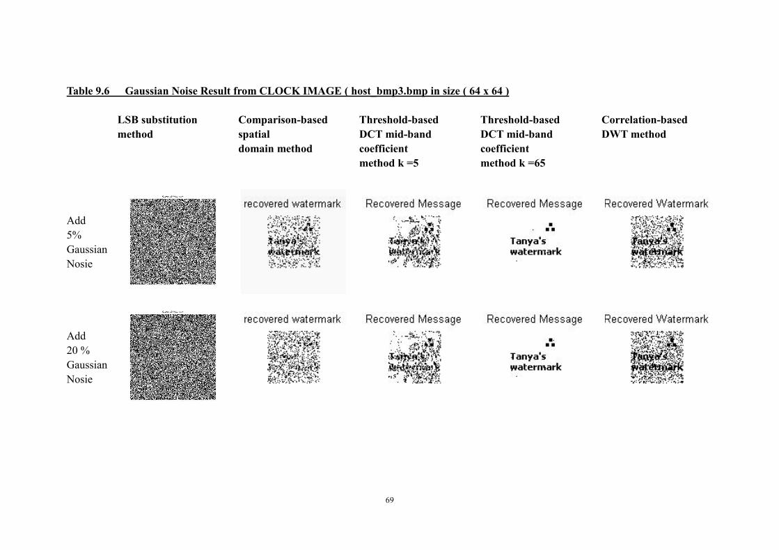
69
Table 9.6 Gaussian Noise Result from CLOCK IMAGE ( host_bmp3.bmp in size ( 64 x 64 )
LSB substitution
method
Comparison-based
spatial
domain method
Threshold-based
DCT mid-band
coefficient
method k =5
Threshold-based
DCT mid-band
coefficient
method k =65
Correlation-based
DWT method
Add
5%
Gaussian
Nosie
Add
20 %
Gaussian
Nosie

70
Table 9.7 JPG Compression Result from CLOCK IMAGE ( host_bmp3.bmp in size ( 64 x 64 )
LSB substitution
method
Comparison-based
spatial
domain method
Threshold-based
DCT mid-band
coefficient
method k =5
Threshold-based
DCT mid-band
coefficient
method k =65
Correlation-based
DWT method
JPG
Compression
Quality 25
JPG
Compression
Quality 90

71
Table 9.8 Median Filtering Result from CLOCK IMAGE ( host_bmp3.bmp in size ( 64 x 64)
LSB substitution
method
Comparison-based
spatial
domain method
Threshold-based
DCT mid-band
coefficient
method k =5
Threshold-based
DCT mid-band
coefficient
method k =65
Correlation-based
DWT method
1-D
Median
fitler
2-D
Median
filter

72
Table 9.9 Gaussian Noise Result from CLOCK IMAGE ( host_bmp3.bmp in size ( 128 x 128 )
LSB substitution
method
Comparison-based
spatial
domain method
Threshold-based
DCT mid-band
coefficient
method k =5
Threshold-based
DCT mid-band
coefficient
method k =65
Correlation-based
DWT method
Add
5%
Gaussian
Nosie
128 × 128 watermark is
too big in this method
128 × 128 watermark is
too big in this method
Add
20 %
Gaussian
Nosie
128 × 128 watermark is
too big in this method
128 × 128 watermark is
too big in this method

73
Table 9.10 JPG Compression Result from CLOCK IMAGE ( host_bmp3.bmp in size ( 128 x 128 )
LSB substitution
method
Comparison-based
spatial
domain method
Threshold-based
DCT mid-band
coefficient
method k =5
Threshold-based
DCT mid-band
coefficient
method k =65
Correlation-based
DWT method
JPG
Compression
Quality 25
128 × 128 watermark
is too big in this
method
128 × 128 watermark
is too big in this
method
JPG
Compression
Quality 90
128 × 128 watermark
is too big in this
method
128 × 128 watermark
is too big in this
method

74
Table 9.11 Median Filtering Result from CLOCK IMAGE ( host_bmp3.bmp in size ( 128 x 128 )
LSB substitution
method
Comparison-based
spatial
domain method
Threshold-based
DCT mid-band
coefficient
method k =5
Threshold-based
DCT mid-band
coefficient
method k =65
Correlation-based
DWT method
1-D
Median
fitler
128 × 128 watermark is
too big in this method
128 × 128 watermark is
too big in this method
2-D
Median
filter
128 × 128 watermark is
too big in this method
128 × 128 watermark is
too big in this method

75
Table 9.12
Gaussian Noise Result from Miss Herbun (host_bmp.bmp in size ( 64 x 64 ):
LSB, Recovered Watermark after addition of 5
% Gaussian Noise
LSB, Recovered Watermark after medium
filtering,
SPD, Recovered Watermark after addition of 5
% Gaussian Noise
SPD, Recovered Watermark after medium
filtering,
Mid-Band, Recovered Watermark after addition
of 5 % Gaussian Noise
Mid-band, Recovered Watermark after medium
filtering,
DWT, Recovered Watermark after addition of 5
% Gaussian Noise
DWT, Recovered Watermark after medium
filtering,

76
Table 9.13
JPG Compression Result from Miss Herbun ( host_bmp.bmp in size ( 64 x 64 ):
LSB, Recovered Watermark after JPG
compressing ,Quality =25
LSB, Recover Watermark after JPG
compressing, Quality =90
Mid-band, Recovered Watermark after JPG
Compressing, Quality =25
Mid-band, Recover Watermark after JPG
compressing, Quality =90
SPD, Recovered Watermark after JPG
Compressing, Quality =25
SPD, Recover Watermark after JPG
compressing, Quality =90
DWT, Recovered Watermark after JPG
Compressing, Quality =25
DWT, Recover Watermark after JPG
compressing, Quality =90

77
Table 9.14 PSNR value Comparison table
This value is recorded when embed the 64 x 64 watermark into host images.
Methods:
(watermark size 64 x 64 pixel)
PSNR value
(dB)
miss_hepburn.
PSNR Value
(dB)
baboon
PSNR value
(dB)
Clock
Spatial Domain
LSB substitution method 55.80 50.10 11.46
Correlation-based method
Spatial method 43.66 29.76 11.55
Discrete Cosine Transform Domain
Threshold-based Mid-band
DCT coefficients 41.50 (k=5)
25.78 (k=65)
41.38 (k =5)
19.48 (k = 65)
42.60 ( k =5)
20.90(k = 65)
Discrete Wavelet Transform Domain
Correlation-based of DWT
method 43.54(k =2) 26.86 (k =2) 35.67 (k =2)

78
Table 9.15 Processing time Comparison results
Methods: Processing
type
Watermark
32 × 32 pixel
Watermark
64 × 64
pixel
Watermark
128 × 128
pixel
Spatial Domain
Embed 1.24 sec 0.82 sec 1.20 sec LSB substitution
(miss_hepburn) Recover 2.27 sec 2.27 sec 2.58 sec
Embed 1.12 sec 0.76 sec 1.12 sec LSB substitution
(baboon) Recover 2.43 sec 2.43 sec 2.74 sec
Embed 1.10 sec 1.10 sec 1.11 sec LSB substitution
(clock) Recover 2.67 sec 2.67 sec 2.67 sec
Embed 2.02 sec 2.02 sec 3.62 sec Correlation-based in
Spatial Domain
(miss_hepburn)
Recover 0.35 sec 0.35 sec 0.42 sec
Embed 3.73 sec 3.73 sec 5.24 sec Correlation-based in
Spatial Domain (baboon) Recover 0.38 sec 0.38 sec 0.51 sec
Embed 2.26 sec 2.28 sec 2.56 sec Correlation-based in
Spatial Domain (Clock) Recover 0.33 sec 0.36 sec 0.45 sec
Discrete Cosine Transform Domain
Embed 2.97/2.97 sec 2.63/2.84
sec N/A
Threshold-based of
DCT Mid-band
Coefficients,
k = 5/65 , (miss_hepburn) Recover 2.06/2.13 sec
1.76/1.81
sec N/A
Embed 2.91/22.91sec 2.57/2.95
sec N/A
Threshold-base DCT
Mid-band
Coefficients, k = 5/65
(baboon) Recover 4.20/1.82 sec
1.74/1.82
sec N/A
Embed 2.96/2.93 sec 2.55/2.84
sec N/A
Threshold-based DCT
Mid-band Coefficients, k =
5/65
(clock) Recover 4.01/1.59 sec
1.77/2.95
sec N/A
Discrete Wavelet Transform Domain
Embed 18.45 sec
(k = 2)
31.18 sec
(k = 2)
130.23 sec
(k = 2)
Correlation-based DWT
Method (miss_herpbun),
k = 2 Recover 34.55 sec
(k = 2)
54.70 sec
(k = 2)
217.67 sec
(k = 2)
Embed 19.33 sec
(k = 2)
31.32 sec
(k = 2)
122.78 sec
(k = 2)
Correlation-based DWT
Method, (baboon),
k = 2 Recover 34.55 sec
(k = 2)
52.03 sec
(k = 2)
213.25 sec
(k = 2)

79
Embed 19.43 sec
(k = 2)
31.33 sec
(k = 2)
123.43 sec
(k = 2)
Correlation-based of DWT
Method, (Clock)
k = 2 Recover 37.92 sec
(k = 2)
52.76 sec
(k = 2)
212.87 sec
(k = 2)

80
Appendix B
Code section
1 File name: hwdata.m
%==========================================
% Header file file name: hwdata.m
%==========================================
% This is the header file for all the data information for each method
% Each method just need to load the data when needed.
%-----------------------------------------------------------------------
% Variable Define
%------------------------------------------------------------------------
% host,host_double: create to store the host image data information
% Mh,Nh: size of the host image
% hostdata,messagedata_lsb,messagedata_dctmid,messagedata_dwt,
% messagedata_spd,keydata: hold different data information for each
% watermark technique required
% key, key_int: create to store the secret key image data information, the
% key is used decrypt the original watermark message
% message1,message2,message3,messge4: create to store watermark message
% data for each method(watermark message are binary images)
% Mm1,Nm1,Mm2,Nm2,Mm3,Nm3,Mm4,Nm4: the sizes of each watermark message
% read_wmark,read_key: creat to store the watermark image and key image
%------------------------------------------------------------------------
% - code Starts –
%------------------------------------------------------------------------
% Load two Host images data
%------------------------------------------------------------------------
% host = imread('host_bmp.bmp');
% host = imread('host_bmp2.bmp');
host = imread('host_bmp3.bmp');
host_double = double(host);
Mh = size(host,1); %Height
Nh = size(host,2); %Width
%------------------------------------------------------------------------
% LSB original Watermark information
%------------------------------------------------------------------------
read_wmark = imread('_tanyacopyright32.bmp','bmp');
%read_wmark = imread('_tanyacopyright64.bmp','bmp');
%read_wmark = imread('_tanyacopyright128.bmp','bmp');

81
message1 = double(read_wmark);
message1=round(message1./256);
message1=uint8(message1);
Mm1 = size(message1,1); %Height
Nm1 = size(message1,2); %Width
%------------------------------------------------------------------------
% DCT in mid band Frequency original watermark Information
%------------------------------------------------------------------------
read_wmark = imread('_tanyacopyright32.bmp','bmp');
%read_wmark = imread('_tanyacopyright64.bmp','bmp');
%read_wmark = imread('_tanyacopyright128.bmp','bmp');
message2 = double(read_wmark);
message2 = round(message2./256);
message2 = uint8(message2);
[Mm2,Nm2] = size(message2); % Height and Width
%------------------------------------------------------------------------
% DWT domain method original watermark information
%------------------------------------------------------------------------
read_wmark = imread('_tanyacopyright32.bmp');
%read_wmark = imread('_tanyacopyright64.bmp','bmp');
%read_wmark = imread('_tanyacopyright128.bmp','bmp');
message3 = double(read_wmark);
[Mm3,Nm3]= size(message3); % Height and Width
%------------------------------------------------------------------------
% Correlation base in Spatial domain method original watermark information
%------------------------------------------------------------------------
read_wmark = imread('_tanyacopyright32.bmp','bmp');
%read_wmark = imread('_tanyacopyright64.bmp','bmp');
%read_wmark = imread('_tanyacopyright128.bmp','bmp');
message4 = double(read_wmark);
message4 = round(message4./256);
%message4=uint8(message4);
Mm4 = size(message4,1); %Height
Nm4 = size(message4,2); %Width
%------------------------------------------------------------------------
% Sercet key information
%------------------------------------------------------------------------
read_key = imread('_key.bmp');
key = double(read_key)./256;
key_int =uint8(key);
%------------------------------------------------------------------------

82
% Save data into package for each methods
%------------------------------------------------------------------------
save 'hostdata' host host_double Mh Nh;
save 'messagedata_lsb' message1 Mm1 Nm1;
save 'messagedata_dctmid' message2 Mm2 Nm2;
save 'messagedata_dwt' message3 Mm3 Nm3;
save 'messagedata_spd' message4 Mm4 Nm4;
save 'keydata' key key_int;
clear host Mh Nh;
clear message1 message2 message3 message4 Mm1 Nm1 Mm2 Nm2 Mm3 Nm3 Mm4 Nm4 ;
% - Code Ends -
2 File name: Similar.m
%=============================================
% Similar function for linear correlation detection
%=============================================
% this function is for compare the degree of similarity of vectors
% Veriable Define
%-----------------------------------------------------------------
% sim: the correlations between vector x and vector y
%-----------------------------------------------------------------
% - Code Starts -
function correlation = similar(vector_x,vector_y)
[a,b] = size(vector_x);
if(c ~= 1& r ~= 1)
error('The error: vector_x should be vector')
end
if(a >1)&&(b ==1)
vector_x = vector_x (:);
end
[b ,a]= size(vector_y);
if(a ~= 1 & b ~= 1)
error('The error: vector_y should be vector')
end
if(c>1)&&(r==1)
vector_y = vector_y (:);
end
correlation = vector_x r * vector_y /sqrt (vector_yr * vector_y);

83
% - Code Ends -
3 File name: psnr.m
%=================================================
%Compute the peak value noise
%=================================================
% this program is calculate psnr value between host image and watermarked image
%---------------------------------------------------------------
% Variables Define
%---------------------------------------------------------------
% host_image: Original host Image
% wmarked_image: Watermarked Image
% value: peak value noise peak value
%---------------------------------------------------------------
% - Code Starts -
function value =PSNR(host_image, wmarked_image)
% convert input images
[m n]= size(host_image);
A = host_image;
B = wmarked_image;
if(size(host_image) ~= size(wmarked_image))
error('Error: The two input images must be the same size');
end
% avoid divide by zero
if ((sum(sum(A-B)))==0)
error('Input images must not be identical');
value = 0;
else
if(~isrgb(host_image)&~isrgb(wmarked_image))
sumaDif = 0;
psnr_max = m * n * max(max(A.^2));
for u =1:m
for v = 1:n
sumaDif = sumaDif + (A(u,v)-B(u,v))^2;
end
end
if(sumaDif == 0)
sumaDif = 1;

84
end
value=psnr_max/sumaDif;
value=abs(10 * log10(value));
end
end
% - Code Ends -
4 Method one Embed section ,File name: lsb.m
%==============================================
% Least Significant Bit watermarking method
%==============================================
%this method is a simple method which directly apply the watmark into the
%least significant bit of the host image, the embedder replace that bit of
%a Work with a given watermark.
%----------------------------------------------
% Define VARIABLES
%----------------------------------------------
% blockVno,blockHno: vertical and horizontal numbers of block the host
% image will be divided into
% start_time,elaspsed_time: caculate speed of embed and detect process
% time
% watermark: enlarge size of the small watermark message, the size is equal
% to host image
% watermarked: host image after watermark message embedded
% m,n,i,j,p,q: temporary variable for loop use
%----------------------------------------------
% - Code starts -
clear all;
% Time start time
start_time=cputime;
load 'hostdata';
load 'messagedata_lsb';
%-------------------------------------------------------
% Make the message image as the same size as the host image
%-------------------------------------------------------
watermark = zeros(Mh,Nh);
m = 0;

85
for i =1 : Mh
n = 0;
for j = 1: Nh
if j >Nm1*n
n = n+1;
end
q = j-(Nm1*(n-1));
if i >Mm1*m
m = m+1;
end
p = i-(Mm1*(m-1));
watermark(i,j) = message1(p,q);
end
end
%-------------------------------------------------------
%Next add the watermark to the lsb bits of host (ii,jj)
%-------------------------------------------------------
watermarked=host;
for i = 1:Mh
for j = 1:Nh
watermarked(i,j)=bitset(watermarked(i,j),1,watermark(i,j));
end
end
%-------------------------------------------------------
% save watermarked image
%-------------------------------------------------------
imwrite(watermarked,'lsb_watermarked.bmp','bmp');
%-------------------------------------------------------
% display watermarked image and Extra information
%-------------------------------------------------------
figure(1)
imshow(watermarked,[])
title('Watermarked Image')
%display processing time
elapsed_time=cputime-start_time,
% calculate the PSNR value
%a = double(imread('host_bmp.bmp'));
%a = double(imread('host_bmp2.bmp'));
a = double(imread('host_bmp3.bmp'));
b = double(imread('lsb_watermarked.bmp'));

86
psnr = PSNR(a,b),
% - Code Ends -
5 Method one Extract section, File name: lsbrecover.m
%==============================================
% LSB substitution Extraction Method
%==============================================
%Variable Define
%----------------------------------------------
%watermark_image: host image with watermark message embeded
%watermark: watermark which has been reconstructed after attack
%Mw,Nw: the size of the watemark message
%----------------------------------------------
% - Code Starts -
clear all;
% save start time
start_time=cputime;
%load in watermarked image or choose a attacked image
watermarked_image=double(imread('lsb_watermarked.bmp','bmp'));
%------------------------------------------------------------
% extract watermark after attacks,need customize
%------------------------------------------------------------
%read_image = double(imread('lsbscale50.jpg'));
%read_image = double(imread('lsbcrop.jpg'));
%read_image = double(imread('lsbgaussin_J30.jpg'));
%read_image = double(imread('lsbgaussin_J05.jpg'));
%read_image = double(imread('lsbjpegcompression1_J25.jpg'));
%read_image = double(imread('lsbjpegcompression1_J90.jpg'));
%read_image = double(imread('lsbmedfilt1_J100.jpg'));
%read_image = double(imread('lsbmedfilt2_J100.jpg'));
%watermarked_image = read_image(:,:,3);
% determine size of watermarked image
[Mw Nw]=size(watermarked_image);
% use lsb of watermarked image to recover watermark
for i = 1:Mw
for j = 1:Nw

87
watermark(i,j)=bitget(watermarked_image(i,j),1);
end
end
% scale the recovered watermark
watermark=256*double(watermark);
%----------------------------------------------------------------------------
% scale and display recovered watermark and speed of process
%----------------------------------------------------------------------------
figure(1)
imshow(watermark,[ ])
title('Recovered Watermark')
% display processing time
elapsed_time=cputime-start_time,
% save recovered watermark,this section need customize
%imwrite(watermark,'recovermf1.jpg','jpg');
% - Code Ends -
6 Method two Embed section, File name: spd.m
%=========================================================
% Method 4: Comparison base method in Spatial Domain
%=========================================================
%This method is a very adoptive method for spatial domain
% Variable Define
%---------------------------------------------------------
% start_time: recording the start time of this method
% host: host image
% hostr: watermarked image
% wmark: contain the watermark message
% messagev: a row vector store the wmark message
% wmarkvs: a row vector store the encoded wmark message
% blockv: contain the imformation of certain block of original image
% blockvr: contain the imformation host image with watermark embed
% embed_algorithm: function of embeding watermark,by giving input
% psnr: calculate psnr value between orignal host image and watermarked
% image
% indrow/indcol: The PN sequence index of blocks
%---------------------------------------------------------
% - Code Starts -

88
clear all;
%recording starting time
start_time = cputime;
load hostdata % Loading host image and watermark image information from hwdata.m
load messagedata_spd
load keydata
wmark = message4;
%---------------------------------------------------------
%The following section embeds the watermark into the host image.
%---------------------------------------------------------
host = host(:,1:512);
host = double(host);
hostr = zeros(size(host));
%---------------------------------------------------------
% Encoding the watermark,
%---------------------------------------------------------
%generate a vector of the watermark image pixel values in raster scan form
messagev= wmark(1,:);
for i=2:Mm4
messagev = [messagev wmark(i,:)];end;
rand('state',13); % reuse the intial state in extract watermark method as well
indp = randperm(Mm4*Nm4); %generating a randomly permuted vector of indices
for i = 1:length(indp)
wmarkvs(i) = messagev(indp(i));end; %encoding the wmark vector
clear messagev indp;
%---------------------------------------------------------
%generating the watermarked image
%---------------------------------------------------------
for i=1:Mm4, wmarks(i,:) = wmarkvs((i-1)*Nm4+1:i*Nm4);end; clear wmarkvs;
% Mh, Nh are the size of host image
rand('state',11); %setting the random generator to known state
indrow = randperm(Mh/4); %generating row indices for random embedding of watermark
rand('state',7); %setting th4e random generator to known state
indcol = randperm(Nh/4); %generating column indices for random embedding of watermark
rand('state',sum(100*clock)); %setting the random generator to a random state for delta

89
for i=1:Nh/4 % 4 can be change when the different size of watermark is embed
for j=1:Mh/4
bit = wmarks(i,j); %the bit to be embedded
irow = indrow(i)-1; icol = indcol(j)-1; %row/column indices of host target block
rlo=4*irow+1; rhi=4*irow+4; clo=4*icol+1; chi=4*icol+4;
blockv = [host(rlo,clo:chi) host(rlo+1,clo:chi) host(rlo+2,clo:chi)
host(rlo+3,clo:chi)];
%---------------------------------------------------------
% for small size of watermark use
%---------------------------------------------------------
% rlo=8*irow+1; rhi=8*irow+8; clo=8*icol+1; chi=8*icol+8;
% blockv = [host(rlo,clo:chi) host(rlo+1,clo:chi) host(rlo+2,clo:chi)
% host(rlo+3,clo:chi) host(rlo+4,clo:chi) host(rlo+5,clo:chi)
% host(rlo+6,clo:chi) host(rlo+7,clo:chi)];
% reconstructed host image block with the embedded bit:
blockvr = embed_algorithm(blockv,bit); use embed_algorithm function
hostr(rlo:rhi,clo:chi) = [blockvr(1:4); blockvr(5:8); blockvr(9:12); blockvr(13:16)];
%---------------------------------------------------------
% for small size of watermark when reconstructed the watermarked image
%---------------------------------------------------------
% hostr(rlo:rhi,clo:chi)= [blockvr(1:8); blockvr(9:16); blockvr(17:24);
blockvr(25:32);
% blockvr(33:40); blockvr(41:48); blockvr(49:56); blockvr(57:64);];
end;
end;
clear indrow indcol irow icol block blockr blockv blockvr gmean gmax gmin mhi mlo;
clear bit Cb Cmin alpha delta hi lo Mm4 Nm4 Mh Nh i j k rlo rhi clo chi wmarks;
%---------------------------------------------------------
%Display Result Image and more processing speed
%---------------------------------------------------------
figure(1);clf;
imshow(hostr,[0,255],'truesize');title('Watermarked Image');
imwrite(uint8(hostr),gray(256),'spatial_wmarked.bmp','bmp');
% display processing time
elapsed_time=cputime - start_time,
% calculate the PSNR value

90
a = double(imread('host_bmp.bmp'));
%a = double(imread('host_bmp2.bmp'));
% a= double(imread('host_bmp3.bmp'));
b = double(imread('spatial_wmarked.bmp'));
psnr = PSNR(a,b), % apply psnr function
clear host hostr wmark;
% - Code Ends -
7 Method two Embed section, embed algorithm File name: embed_algorithm.m
%==================================================
% Embed watermark function for spd.m
% =================================================
%variable Define
%--------------------------------------------------
% gmax: maxinum intensity of blockv
% gmean : average intensity of blockv
% gmin: mininum intensity of blockv
% lo/hi/mhi/mlo: gether pixels in two fashion,
% wmarked: watermarked image
%--------------------------------------------------
% - Code starts -
function wmarked = embed_algorithm(blockv, bit)
wmarked = ones(size(blockv)); %vector of embedded target block pixels
rand('state',sum(100*clock));
gmax = max(blockv);
gmean = sum(blockv)/16+1; %getting the mean, min, and max for the block
gmin = min(blockv);
lo = find(blockv <= gmean); %indices for pixels above and below the mean
hi = find(blockv > gmean);
if length(blockv(hi))~=0, % avoid when divide by 0
mhi = sum(blockv(hi))/length(blockv(hi));
else
mhi = 0;
end
mlo = sum(blockv(lo))/length(blockv(lo)); %getting the upper and lower region means
Cmin = 1;% minimum block change, the value can be customised:
k = 0.1; %value arbitrary: this value can be customised as well
% put the bites form image into two group , high and low intensity blocks

91
Cb = max(Cmin,alpha*(gmax-gmin)); %setting the block contrast value
for k = 1:length(blockv),
delta = rand*Cb; % generate a random value
if bit == 1,
if blockv(k) > mhi, wmarked(k)=gmax;
elseif (blockv(k) >= mlo) && (blockv(k) < gmean), wmarked(k)=gmean;
else wmarked(k) = blockv(k) + delta;
end
end
if bit == 0,
if blockv(k) < mlo, wmarked(k) = gmin;
elseif (blockv(k) >= gmean) && (blockv(k) < mhi), wmarked(k)=gmean;
else wmarked(k) = blockv(k) - delta;
end
end
end
% - Code Ends -
8 Method two Extract Section, file name: spdrecover.m
%===================================================
% This section is for Recovering watermark
%===================================================
%Variable Define:
%---------------------------------------------------
%host: host image
%hostr: host image with watermark embedded
%messager: recovered, descrambled watermark
%messagesr: recovered scrambled watermark
%message_vectorr: descrambled watermark vector
%---------------------------------------------------
% - Code starts -
clear;
%Recording the start time
start_time =cputime;
% loading the host image and watermark message
load hostdata
load messagedata_spd
load keydata

92
% load watermarked image
message = double(message4);
read_wmarked = imread('spatial_wmarked.bmp');
%-------------------------------------------------------
% extract watermark after attacks,need customize
%-------------------------------------------------------
%read_wmarked = double(imread('spdgaussin_J30.jpg'));
%read_wmarked = double(imread('spdgaussin_J05.jpg'));
%read_wmarked = double(imread('spdjpegcompression1_J25.jpg'));
%read_wmarked = double(imread('spdjpegcompression1_J90.jpg'));
%read_wmarked = double(imread('spdmedfilt1_J100.jpg'));
%read_wmarked = double(imread('spdmedfilt2_J100.jpg'));
wmark = message4;
wmarkr = zeros(size(wmark));
host = double(host);
wmark = double(wmark);
hostr = double(read_wmarked);
wmarkvr = extract_algorithm(host,Mh,Nh,hostr);
%-------------------------------------------------------
%reconstructs the wmark image from the decoded/descrambled wmark vector
%-------------------------------------------------------
for i=1:Mm4
wmarkr(i,:) = wmarkvr((i-1)*Nm4+1:i*Nm4);end;
clear i wmarkvr;
clear host name num Mm4 Nm4 Mh Nh ;
%-------------------------------------------------------
% Plot the watermarked image
%-------------------------------------------------------
figure(1);clf;
imshow(wmarkr,'truesize');title('recovered watermark');
clear wmark wmarkr;
%display processing time
elapsed_time=cputime-start_time,
% - Code Ends -
9 Method two Extract section algorithm file name: extract_alogrithm.m

93
%=======================================================
%this extract_algorithm function is for spd
%=======================================================
%variable Define
%-------------------------------------------------------
%indd: random permutation of vector indices
%irow/icol: row/column indices based on scrambled indices
%blockn: target block from hostr
%blocko: target block from host
%indrow/indcol: random row/column index vectors for scrambling
%sumn: sum of pixel intensities for target block from hostr
%sumo: sum of pixel intensities for target block from host
%message_vectorrs: raster scan vector of recovered, scrambled watermark
%-------------------------------------------------------
function wmarkvr = extract_algorithm(host,Mh,Nh,hostr); % Mh,Nh are size of host image
load messagedata_spd;
load keydata;
load hostdata;
rand('state',11); %resetting to initial state
indrow = randperm(Mh/4); %row/column indices
rand('state',7);
indcol = randperm(Nh/4);
wmarksr = zeros(Mh/4,Nh/4);
for i=1:Nh/4
for j=1:Mh/4
irow = indrow(i)-1; icol = indcol(j)-1;
blocko = host( 4*irow+1:4*irow+4,4*icol+1:4*icol+4 );
blockn = hostr( 4*irow+1:4*irow+4,4*icol+1:4*icol+4 );
sumo = sum(sum(blocko));
sumn = sum(sum(blockn));
if sumn < sumo
wmarksr(i,j) = 0; %compare blocks to determine 0 or 1
elseif sumn >= sumo
wmarksr(i,j) = 1;
end
end
end
clear h blocko blockn i j icol indcol irow indrow sumo sumn;
%-------------------------------------------------------
%building the recovered but encoded watermark vector

94
%-------------------------------------------------------
wmarkvrs = wmarksr(1,:);
for i=2:Mm4,
wmarkvrs = [wmarkvrs wmarksr(i,:)];end;
clear messagesr;
rand('state',13); %resetting the seed for the random # generator
indd = randperm(Mm4 * Nm4); %recovering the random index vector for descrambling
wmarkvr = zeros(size(wmarkvrs));
%-------------------------------------------------------
%Decoding watermark
%-------------------------------------------------------
for i=1:length(indd)
wmarkvr(indd(i)) = wmarkvrs(i);end;
clear message_vectorrs;
% - Code Ends -
8 Method three Embed section file name: dctmidband.m
%=================================================================
% Threshold base of DCT Midband coefficients method ,file name: dctmidband.m
%=================================================================
% this method use image block, use fix random sequence represent 0 & 1,
% embed in DCT intermediate frequency
%-----------------------------------------------------------------
% Variable Define
%-----------------------------------------------------------------
% k: this parameter can be customrized , default value is 5,
% blocksize: DCT coefficient
% midband: Define the midband coefficient t
% message_max: threshold of the biggest message can embed to host
% message_vector: hold congruous watermark message
% pn_sequence_search : find highly uncorrelated pn sequences{T,F}
% pn_sequence_one/pn_sequence_zero: random PN sequences
% watermarked_image/watermarked_image_int: hold the watermarked image
%-----------------------------------------------------------------
% - Code starts -
clear all;

95
load 'hostdata'
load 'messagedata_dctmid'
load 'keydata'
% Recording start time
start_time=cputime;
k = 5
%k=65 % set a gain factor for embeding, this can customrize
blocksize=8; % set blocksize for DCT
pn_sequence_search= 'T';
% Define a mid band frequencie with 8 x 8 dct
midband=[ 0,0,0,1,1,1,1,0;
0,0,1,1,1,1,0,0;
0,1,1,1,1,0,0,0;
1,1,1,1,0,0,0,0;
1,1,1,0,0,0,0,0;
1,1,0,0,0,0,0,0;
1,0,0,0,0,0,0,0;
0,0,0,0,0,0,0,0 ];
%------------------------------------------------------------
% determine maximum message size (threshold) based on host image, and blocksize
%------------------------------------------------------------
message_max = Mh * Nh /(blocksize^2);
%------------------------------------------------------------
% reshape the message to a vector
%------------------------------------------------------------
message2 = round(reshape(message2,Mm2 * Nm2,1));
% check that the watermark message isn't excess threhold of image
if (length(message2) > message_max)
error('Message too large to fit in Cover Object')
end
%------------------------------------------------------------
% pad the message out to the maximum message size with ones's
%------------------------------------------------------------
message_vector=ones(1,message_max);
message_vector(1:length(message2))=message2;

96
%------------------------------------------------------------
% generate shell of watermarked image
%------------------------------------------------------------
watermarked_image=host;
% reset PN generator to state "key"
rand('state',key);
%------------------------------------------------------------
% generate PN sequences for "1" and "0"
%------------------------------------------------------------
pn_sequence_one=round(2*(rand(1,sum(sum(midband)))-0.5));
pn_sequence_zero=round(2*(rand(1,sum(sum(midband)))-0.5));
%------------------------------------------------------------
% find highly un-correlated PN sequences, separately
%------------------------------------------------------------
if (pn_sequence_search=='T')
while (corr2(pn_sequence_one,pn_sequence_zero) > -0.5)
pn_sequence_one=round(2*(rand(1,sum(sum(midband)))-0.5));
pn_sequence_zero=round(2*(rand(1,sum(sum(midband)))-0.5));
end
end
%------------------------------------------------------------
% process the image in blocks
%------------------------------------------------------------
x=1;
y=1;
for (kk = 1:length(message_vector))
% transform each block of host image in DCT
dct_block=dct2(host(y:y+blocksize-1,x:x+blocksize-1));
% if message bit contains zero then embed pn_sequence_zero into the mid-band
% componants of the dct_block
ll=1;
if (message_vector(kk)==0)
for ii=1:blocksize
for jj=1:blocksize
if (midband(jj,ii)==1)
dct_block(jj,ii)=dct_block(jj,ii)+k*pn_sequence_zero(ll);
ll=ll+1;
end

97
end
end
% otherwise, embed pn_sequence_one into the mid-band componants of dct_block
else
for ii=1:blocksize
for jj=1:blocksize
if (midband(jj,ii)==1)
dct_block(jj,ii)=dct_block(jj,ii)+k*pn_sequence_one(ll);
ll=ll+1;
end
end
end
end
%------------------------------------------------------------
% transform block back into spatial domain
%------------------------------------------------------------
watermarked_image(y:y+blocksize-1,x:x+blocksize-1)=idct2(dct_block);
if (x+blocksize) >= Nh
x=1;
y=y+blocksize;
else
x=x+blocksize;
end
end
watermarked_image_int=uint8(watermarked_image);
%imwrite(watermarked_image_int,'dctmid_watermarkedk05.bmp','bmp');
imwrite(watermarked_image_int,'dctmid_watermarkedk65.bmp','bmp');
%------------------------------------------------------------
% display watermarked image
%------------------------------------------------------------
figure(1)
imshow(watermarked_image_int,[])
title('Watermarked Image')
% display processing time
elapsed_time=cputime-start_time,
% calculate the PSNR value
a = double(imread('host_bmp.bmp'));

98
%a = double(imread('host_bmp2.bmp'));
%a = double(imread('host_bmp3.bmp'));
b = double(imread('dctmid_watermarkedk65.bmp','bmp'));
%b = double(imread('dctmid_watermarkedk65.bmp','bmp'));
psnr = PSNR(a,b),
% - Code Ends -
10 Method three Extract section algorithm file name: dctmidrecover.m
%=================================================================
% Extract watermark after distortion watermarked image, file name:
%=================================================================
% The dectection of watermark existance can realize detection their
% linear correlation
%-----------------------------------------------------------------
% Variable Define
%-----------------------------------------------------------------
% blocksize: DCT coefficient
% midband: Define the midband coefficient t
% message_max: threshold of the biggest message can embed to host
% message_vector: hold congruous watermark message
% pn_sequence_search : find highly uncorrelated pn sequences{T,F}
% pn_sequence_one/pn_sequence_zero: random PN sequences
%-----------------------------------------------------------------
% - Code Starts -
clear all;
load 'messagedata_dctmid'
load 'keydata'
% save start time
start_time=cputime;
blocksize=8; % set blocksize
pn_sequence_search='T'; % perform search to find highly uncorrelated pn sequences {T,F}
midband=[ 0,0,0,1,1,1,1,0; % defines the mid-band frequencies of an 8x8 dct
0,0,1,1,1,1,0,0;
0,1,1,1,1,0,0,0;
1,1,1,1,0,0,0,0;
1,1,1,0,0,0,0,0;

99
1,1,0,0,0,0,0,0;
1,0,0,0,0,0,0,0;
0,0,0,0,0,0,0,0 ];
% read in the watermarked object
file_name='dctmid_watermarkedk65.bmp';
watermarked_image=double(imread(file_name));
%------------------------------------------------------------
% Extract watermark after attacks, file_name need customize
%------------------------------------------------------------
%file_name= 'midscale50.jpg';
%file_name= 'midcrop.jpg';
%file_name= 'midmedfilt1_J100.jpg';
%file_name= 'midmedfilt2_J100.jpg';
%file_name= 'midjpegcompression1_J25.jpg';
%file_name= 'midjpegcompression1_J90.jpg';
%file_name= 'midgaussin_J05.jpg';
%file_name= 'midgaussin_J30.jpg';
%watermarked_image=double(imread(file_name));
%watermarked_image=watermarked_image(:,:,3);
% determine size of watermarked image
Mw=size(watermarked_image,1); %Height
Nw=size(watermarked_image,2); %Width
%------------------------------------------------------------
% determine maximum message size based on cover object, and blocksize
%------------------------------------------------------------
message_max=Mw*Nw/(blocksize^2);
% reset MATLAB's PN generator to state "key"
rand('state',key);
% generate PN sequences for "1" and "0"
pn_sequence_one=round(2*(rand(1,sum(sum(midband)))-0.5));
pn_sequence_zero=round(2*(rand(1,sum(sum(midband)))-0.5));
%------------------------------------------------------------
% find two highly un-correlated PN sequences
%------------------------------------------------------------
if (pn_sequence_search=='T')
while (corr2(pn_sequence_one,pn_sequence_zero) > -0.5)
pn_sequence_one=round(2*(rand(1,sum(sum(midband)))-0.5));
pn_sequence_zero=round(2*(rand(1,sum(sum(midband)))-0.5));

100
end
end
% process the image in blocks
x=1;
y=1;
for (kk = 1:message_max)
% transform block using DCT
dct_block=dct2(watermarked_image(y:y+blocksize-1,x:x+blocksize-1));
% extract the middle band coeffcients
ll=1;
for ii=1:blocksize
for jj=1:blocksize
if (midband(jj,ii)==1)
sequence(ll)=dct_block(jj,ii);
ll=ll+1;
end
end
end
%------------------------------------------------------------
% calculate the correlation of the middle band sequence with pn_sequences
% and choose the value with the higher correlation for message
%------------------------------------------------------------
cor_one(kk)=Similar(pn_sequence_one,sequence);
cor_zero(kk)=Similar(pn_sequence_zero,sequence);
if cor_zero(kk) > cor_one(kk)
message_vector(kk)=0;
else
message_vector(kk)=1;
end
% move on to next block. At and of row move to next row
if (x+blocksize) >= Nw
x=1;
y=y+blocksize;
else
x=x+blocksize;
end
end
%------------------------------------------------------------
% reshape the embeded message

101
%------------------------------------------------------------
message=reshape(message_vector(1:Mm2*Nm2),Mm2,Nm2);
% display recovered message
figure(1);
imshow(message,[])
title('Recovered Message')
% display processing time
elapsed_time=cputime - start_time,
% save the recovered watermark, recovered watermark need customize
% imwrite(message,'recoverjpg90.jpg','jpg');
% - Code Ends -

102
11 Method four Embed section file name: dwt.m
%*******************************************************
% Method 4 : Wavelet Domain file name: code5.m
%*******************************************************
% This method apply in wavelet domain which is
% Variable Define:
%-------------------------------------------------------
%wmarked_image_int: store host image data
%wmark: watermark message data
%wmark_vector: a row vector with watermark message data
%pn_sequence_h/pn_sequence_v: random sequence
%wmarked_imagefinal: store watermarked image data
%-------------------------------------------------------
% - Code Starts -
%loading host and watermark image and get their information
clear all;
% save start time
start_time=cputime;
load hostdata;
load messagedata_dwt;
load keydata;
wmarked_image_int =zeros(size(host));
host = double(host);
wmark = message3;
%Decompostion host image level 3
[ca1,ch1,cv1,cd1] = dwt2(host,'haar');
[ca2,ch2,cv2,cd2] = dwt2(ca1,'haar');
[ca3,ch3,cv3,cd3] = dwt2(ca2,'haar');
wmark_vector = round(reshape(message3,Mm3*Nm3,1)./256);
rand('state', key);
k =5 % k is adjustable parameter, a gain factor can add robustness of watermark
for(kk = 1:length(wmark_vector))
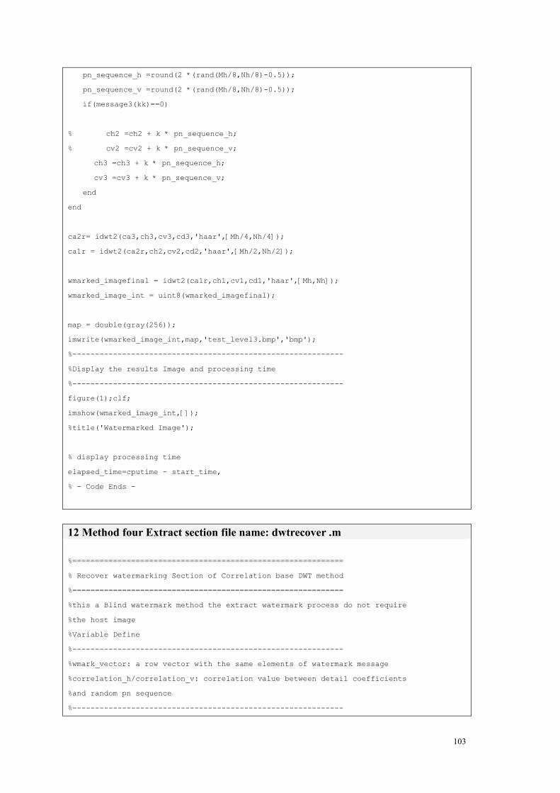
103
pn_sequence_h =round(2 *(rand(Mh/8,Nh/8)-0.5));
pn_sequence_v =round(2 *(rand(Mh/8,Nh/8)-0.5));
if(message3(kk)==0)
% ch2 =ch2 + k * pn_sequence_h;
% cv2 =cv2 + k * pn_sequence_v;
ch3 =ch3 + k * pn_sequence_h;
cv3 =cv3 + k * pn_sequence_v;
end
end
ca2r= idwt2(ca3,ch3,cv3,cd3,'haar',[Mh/4,Nh/4]);
ca1r = idwt2(ca2r,ch2,cv2,cd2,'haar',[Mh/2,Nh/2]);
wmarked_imagefinal = idwt2(ca1r,ch1,cv1,cd1,'haar',[Mh,Nh]);
wmarked_image_int = uint8(wmarked_imagefinal);
map = double(gray(256));
imwrite(wmarked_image_int,map,'test_level3.bmp','bmp');
%------------------------------------------------------------
%Display the results Image and processing time
%------------------------------------------------------------
figure(1);clf;
imshow(wmarked_image_int,[]);
%title('Watermarked Image');
% display processing time
elapsed_time=cputime - start_time,
% - Code Ends -
12 Method four Extract section file name: dwtrecover .m
%============================================================
% Recover watermarking Section of Correlation base DWT method
%============================================================
%this a Blind watermark method the extract watermark process do not require
%the host image
%Variable Define
%------------------------------------------------------------
%wmark_vector: a row vector with the same elements of watermark message
%correlation_h/correlation_v: correlation value between detail coefficients
%and random pn sequence
%------------------------------------------------------------

104
% - Code start -
clear all;
% save start time
start_time=cputime;
% read in the watermarked object
file_name = 'test_level3.bmp';
%file_name='dwt_watermarked.bmp';
watermarked_image=double(imread(file_name));
%------------------------------------------------------------
% load after distortion watermarked image, this need customize
%------------------------------------------------------------
% file_name = imread('dwtscale50.jpg');
% file_name = imread('dwtcrop.jpg');
% file_name = imread('dwtmedfilt1_J100.jpg');
% file_name = imread('dwtmedfilt2_J100.jpg');
% file_name = imread('dwtjpegcompression1_J25.jpg');
% file_name = imread('dwtjpegcompression1_J90.jpg');
% file_name = imread('dwtgaussian_J05.jpg');
% file_name = imread('dwtgaussian_J30.jpg');
% watermarked_image = double(file_name);
% determine size of watermarked image
Mw=size(watermarked_image,1); %Height
Nw=size(watermarked_image,2); %Width
load messagedata_dwt;
load keydata;
load dwt3message;
% reset MATLAB's PN generator to state "key"
rand('state',key);
wmark_vector = ones(1,Mm3*Nm3);
%------------------------------------------------------------
% decompose watermarked image three levels
%------------------------------------------------------------
[ca1,ch1,cv1,cd1] = dwt2(watermarked_image,'haar');
[ca2,ch2,cv2,cd2] = dwt2(ca1,'haar');
[ca3,ch3,cv3,cd3] = dwt2(ca2,'haar');

105
rand('state',key);
%------------------------------------------------------------
% add pn sequences to HL and LH components when message = 0
%------------------------------------------------------------
for (m = 1:length(wmark_vector))
pn_sequence_h= round(2*(rand(Mw/8,Nw/8)-0.5));
pn_sequence_v= round(2*(rand(Mw/8,Nw/8)-0.5));
correlation_h(m)=corr2(ch3,pn_sequence_h);
correlation_v(m)=corr2(cv3,pn_sequence_v);
correlation(m)=(correlation_h(m)+correlation_v(m))/2;
end
for (m=1:length(wmark_vector))
if (correlation(m) > mean(correlation))
wmark_vector(m)= 0;
end
end
% display processing time
elapsed_time=cputime - start_time,
%-------------------------------------------------------------------------
% reshapes the message vector and display recovered watermark.
%--------------------------------------------------------------------------
message3=reshape(wmark_vector,Mm3,Nm3);
figure(1)
imshow(message3,'truesize')
title('Recovered Watermark')
% - Code Ends -
106
MATLAB function description
imshow: From image processing toolbox
Display image
Syntax
• imshow(I)
• imshow(I,[low high])
• imshow(RGB)
• imshow(BW)
• imshow(X,map)
• imshow(filename)
• himage = imshow(...)
• imshow(...,param1,val1,param2,val2)
Description
imshow(I) displays the grayscale image I.
imshow(I,[low high]) displays the grayscale image I, specifying the display range for I in [low high].
The value low (and any value less than low) displays as black; the value high (and any value greater
than high) displays as white. Values in between are displayed as intermediate shades of gray, using
the default number of gray levels. If you use an empty matrix ([]) for [low high], imshow uses
[min(I(:)) max(I(:))]; that is, the minimum value in I is displayed as black, and the maximum value
is displayed as white.
imshow(RGB) displays the truecolor image RGB.
imshow(BW) displays the binary image BW. imshow displays pixels with the value 0 (zero) as
black and pixels with the value 1 as white.
imshow(X,map) displays the indexed image X with the colormap map. A color map matrix may
have any number of rows, but it must have exactly 3 columns. Each row is interpreted as a color,
with the first element specifying the intensity of red light, the second green, and the third blue.
Color intensity can be specified on the interval 0.0 to 1.0.
imshow(filename) displays the image stored in the graphics file filename. The file must contain an
image that can be read by imread or dicomread. imshow calls imread or dicomread to read the
image from the file, but does not store the image data in the MATLAB workspace. If the file
contains multiple images, the first one will be displayed. The file must be in the current directory or
on the MATLAB path.

107
imread: From image processing toolbox
Read image from graphics file
Syntax
• A = imread(filename,fmt)
• [X,map] = imread(filename,fmt)
• [...] = imread(filename)
• [...] = imread(URL,...)
• [...] = imread(...,idx) (CUR, GIF, ICO, and TIFF only)
• [...] = imread(...,'PixelRegion',{ROWS, COLS}) (TIFF only)
• [...] = imread(...,'frames',idx) (GIF only)
• [...] = imread(...,ref) (HDF only)
• [...] = imread(...,'BackgroundColor',BG) (PNG only)
• [A,map,alpha] = imread(...) (ICO, CUR, and PNG only)
Description
The imread function supports four general syntaxes, described below. The imread function also
supports several other format-specific syntaxes. See Special Case Syntax for information about
these syntaxes.
A = imread(filename,fmt) reads a greyscale or color image from the file specified by the string
filename, where the string fmt specifies the format of the file. If the file is not in the current
directory or in a directory in the MATLAB path, specify the full pathname of the location on your
system. For a list of all the possible values for fmt, see Supported Formats. If imread cannot find a
file named filename, it looks for a file named filename.fmt.
imread returns the image data in the array A. If the file contains a grayscale image, A is a
two-dimensional (M-by-N) array. If the file contains a color image, A is a three-dimensional
(M-by-N-by-3) array. The class of the returned array depends on the data type used by the file
format. See Class Support for more information.
For most file formats, the color image data returned uses the RGB color space. For TIFF files,
however, imread can return color data that uses the RGB, CIELAB, ICCLAB, or CMYK color
spaces. If the color image uses the CMYK color space, A is an M-by-N-by-4 array. See the
TIFF-Specific Syntax for more information.
[X,map] = imread(filename,fmt) reads the indexed image in filename into X and its associated
colormap into map. The colormap values are rescaled to the range [0,1].
[...] = imread(filename) attempts to infer the format of the file from its content.

108
[...] = imread(URL,...) reads the image from an Internet URL. The URL must include the protocol
type (e.g., http://).
Suppor format: ‘bmp’, ‘cur’, ‘gif’ , ‘hdf’ , ‘ico’, ‘jpg’, or ‘jpeg’, ‘pbm’, ‘pcx’, ‘pgm’, ‘png’, ‘pnm’
and etc.
uint8: From image processing toolbox
Convert data to unsigned 8-bit integers
Syntax
B = uint8(A)
Description
B = uint8(A) creates the unsigned 8-bit integer array B from the array A. If A is a uint8 array, B is
identical to A.
The elements of a uint8 array can range from 0 to 255. Values outside this range are mapped to 0 or
255. If A is already an unsigned 8-bit integer array, uint8 has no effect.
The fractional part of each value in A is discarded on conversion. This means, for example, that
uint8(102.99) is 102, not 103. Therefore, it is often a good idea to round off the values in A before
converting to uint8. For example,
B = uint8(round(A))
i = uint*(x) converts the vector x into an unsigned integer. x can be any numeric object (such as a
double). The results of a uint* operation are shown in the next table.
Operation Output Range Output Type Bytes per
Element
Output Class
uint8 0 to 255 Unsigned 8-bit integer 1 uint8
uint16 0 to 65535 Unsigned 16-bit integer 2 uint16
uint32 0 to 4294967295 Unsigned 32-bit integer 4 uint32

109
dct2/ idct2: From Image Processing Toolbox
Compute two-dimensional discrete cosine transform
Syntax
• B = dct2(A)
• B = dct2(A,m,n)
• B = dct2(A,[m n])
Description
B = dct2(A) returns the two-dimensional discrete cosine transform of A. The matrix B is the same
size as A and contains the discrete cosine transform coefficients B(k1,k2).
B = dct2(A,m,n) or B = dct2(A,[m n]) pads the matrix A with 0's to size m-by-n before transforming.
If m or n is smaller than the corresponding dimension of A, dct2 truncates A.
Class Support
A can be numeric or logical. The returned matrix B is of class double.
Algorithm
The discrete cosine transform (DCT) is closely related to the discrete Fourier transform. It is a
separable linear transformation; that is, the two-dimensional transform is equivalent to a
one-dimensional DCT performed along a single dimension followed by a one-dimensional DCT in
the other dimension. The definition of the two-dimensional DCT for an input image A and output
image B is
where M and N are the row and column size of A, respectively. If you apply the DCT to real data,
the result is also real. The DCT tends to concentrate information, making it useful for image
compression applications.
This transform can be inverted using idct2.
dwt2/ idwt2: From wavelet Toolbox

110
Single-level discrete 2-D wavelet transform
Syntax
• [cA,cH,cV,cD] = dwt2(X,'wname')
• [cA,cH,cV,cD] = dwt2(X,Lo_D,Hi_D)
Description
The dwt2 command performs a single-level two-dimensional wavelet decomposition with respect to
either a particular wavelet ('wname', see wfilters for more information) or particular wavelet
decomposition filters (Lo_D and Hi_D) you specify.
[cA,cH,cV,cD] = dwt2(X,'wname') computes the approximation coefficients matrix cA and details
coefficients matrices cH, cV, and cD (horizontal, vertical, and diagonal, respectively), obtained by
wavelet decomposition of the input matrix X. The 'wname' string contains the wavelet name.
[cA,cH,cV,cD] = dwt2(X,Lo_D,Hi_D) computes the two-dimensional wavelet decomposition as
above, based on wavelet decomposition filters that you specify.
• Lo_D is the decomposition low-pass filter.
• Hi_D is the decomposition high-pass filter.
Lo_D and Hi_D must be the same length.
Let sx = size(X) and lf = the length of filters; then size(cA) = size(cH) = size(cV) = size(cD) = sa
where sa = ceil(sx/2), if the DWT extension mode is set to periodization. For the other extension
modes, sa = floor((sx+lf-1)/2).
For information about the different Discrete Wavelet Transform extension modes, see dwtmode.
[cA,cH,cV,cD] = dwt2(...,'mode',MODE) computes the wavelet decomposition with the extension
mode MODE that you specify.
MODE is a string containing the desired extension mode.
An example of valid use is
• [cA,cH,cV,cD] = dwt2(x,'db1','mode','sym');

111
corr2: From image processing Toolbox
Compute the two-dimensional correlation coefficient between two matrices
Syntax
• r = corr2(A,B)
Description
r = corr2(A,B) computes the correlation coefficient between A and B, where A and B are matrices
or vectors of the same size.
Class Support
A and B can be numeric or logical. The return value r is a scalar double.
Algorithm
corr2 computes the correlation coefficient using
where = mean2(A), and = mean2(B).
bitget: MATLAB Function
Get bit at specified position
Syntax
• C = bitget(A, bit)
Description
C = bitget(A, bit) returns the value of the bit at position bit in A. Operand A must be an unsigned
integer or an array of unsigned integers, and bit must be a number between 1 and the number of bits
in the unsigned integer class of A (e.g., 32 for the uint32 class).
Example

112
The dec2bin function converts decimal numbers to binary. However, you can also use the bitget
function to show the binary representation of a decimal number. Just test successive bits from most
to least significant:
• disp(dec2bin(13))
• 1101
• C = bitget(uint8(13), 4:-1:1)
• C =
• 1 1 0 1
randperm: MATLAB function
Random permutation
Syntax
• p = randperm(n)
Description
p = randperm(n) returns a random permutation of the integers 1:n.
Remarks
The randperm function calls rand and therefore changes rand's state.
Examples
randperm(6) might be the vector
• [3 2 6 4 1 5]
or it might be some other permutation of 1:6

113