Embed Size (px)
Citation preview

Robustel GoRugged M1000 USB Quick Guide
RT_QG_M1000 USB _v.1.0.0 25.01.2014 1 /7
Robustel GoRugged M1000 USB Quick Guide
Chapter 1. Interface Introduction
1.1 Overview
1.2 LED Indicators
After inserting the SIM card into the modem and power on, the LED indicator’s status should be as follow when work
normally:
Name Function
NET Registered to the network: 75 ms on / 3 s off
Note: Please refer to Robustel GoRugged M1000 USB User Guide to get more details about the LED indicators.
1.3 USB Interface
USB Cable connector (Type A Male to Type A Male)
USB 2.0 Connector
PIN Description)
1 VCC
2 Data (D-)
3 Data (D+)
4 GND
Robustel GoRugged M1000 USB Quick Guide
RT_QG_M1000 USB _v.1.0.0 25.01.2014 2 /7
1.4 Grounding the Modem
Grounding and wire routing help limit the effects of noise due to electromagnetic interference (EMI). Run the ground
connection from the ground screw to the grounding surface prior to connecting devices.
Note: This product is intended to be mounted to a well-grounded mounting surface, such as a metal panel.
1.5 Power Supply
The power supply range is 9 to 36VDC.
Note: Please take care about the polarity, and do not make reverse connection.
Chapter 2. Hardware Installation
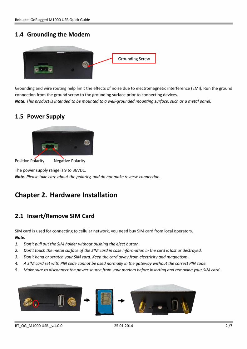
2.1 Insert/Remove SIM Card
SIM card is used for connecting to cellular network, you need buy SIM card from local operators.
Note:
1. Don’t pull out the SIM holder without pushing the eject button.
2. Don’t touch the metal surface of the SIM card in case information in the card is lost or destroyed.
3. Don’t bend or scratch your SIM card. Keep the card away from electricity and magnetism.
4. A SIM card set with PIN code cannot be used normally in the gateway without the correct PIN code.
5. Make sure to disconnect the power source from your modem before inserting and removing your SIM card.
Positive Polarity Negative Polarity
Grounding Screw

Robustel GoRugged M1000 USB Quick Guide
RT_QG_M1000 USB _v.1.0.0 25.01.2014 3 /7
2.2 Connect the External Antenna (SMA Type)
Connect this to external antennas with SMA male connector. Make sure the antenna is for the correct frequency as
your GSM operator with impedance of 50ohm, and also connector is secured tightly.
2.3 Power On and Connect with PC
User can use the USB cable to connect the modem’s USB Connector to external slave devices / controller / computer.
Note: User needs to install relevant USB driver to PC, which you can find out in the CD.
Chapter 3. Operate the Modem
3.1 Install USB driver
1. In the Control Panel, when you install USB cable to PC, it will popup tab Other devices and show M1000 USB’s

Robustel GoRugged M1000 USB Quick Guide
RT_QG_M1000 USB _v.1.0.0 25.01.2014 4 /7
module version.
2. Right-click to enter Properties and then click Update Driver.
3. Click Browse my computer for driver software.

Robustel GoRugged M1000 USB Quick Guide
RT_QG_M1000 USB _v.1.0.0 25.01.2014 5 /7
4. Click Browse to locate the position of the USB driver which can be found out in the CD, then click Next.
5. After succeeding to install the USB driver, it will popup the following window.
6. A simulated virtual COM port which binds to the USB interface of M1000 USB will open after USB driver has been
installed. Please check “Device Manager” -> “Modems”.

Robustel GoRugged M1000 USB Quick Guide
RT_QG_M1000 USB _v.1.0.0 25.01.2014 6 /7
7. Select the USB modem and right-click to enter “Properties”. In tab “Modem”, you will find that there is simulated
COM port which serial software such as secureCRT needs to connect to.
3.2 Start SecureCRT
We can enter AT commands to configure M1000 USB from serial software such as secureCRT, you can download this
software via link: https://app.box.com/s/arkn6xk1asgs1myvuuie.
1. Double click SecureCRT Potable.exe .
2. File->Connect->New Session

Robustel GoRugged M1000 USB Quick Guide
RT_QG_M1000 USB _v.1.0.0 25.01.2014 7 /7
3. Select Protocol as “Serial”.
4. Select the simulated COM port and match the parameters as below, click the “Next” button to finish this session.
Note: You need to disable “RTS/CTS.
5. Configuring the modem with AT command.
Note: Please refer to Robustel GoRugged M1000 USB User Guide to get more details about M1000’ configuration.