Embed Size (px)
Citation preview

IEEJ Journal of Industry ApplicationsVol.2 No.1 pp.40–47 DOI: 10.1541/ieejjia.2.40
Paper
Robust Repetitive Perfect Tracking Control of HDDs Based onRe-learning Scheme
Hiroshi Fujimoto∗ Senior Member
(Manuscript received April 23, 2012, revised Sep. 17, 2012)
This paper presents an improved method of a repetitive controller based on perfect tracking control (PTC) in orderto reject the variable repeatable runout (RRO) of hard disk drives (HDDs). The author’s group proposed repetitivePTC (RPTC) with a switching mechanism. RPTC is realized by using periodic a signal generator (PSG) and PTC. ThePSG produces a feedforward signal from the periodic disturbance, and the PTC generates a control input to cancel theperiodic error in the steady state. However, we have not considered the difference between the RROs of tracks. Thispaper proposes a re-learning scheme by taking into account the correlation of adjacent tracks. Finally, the advantagesof RPTC using the proposed scheme are demonstrated through simulations and experiments using a hard disk driveequipment with discrete track recording media (DTR).
Keywords: multirate control, repeatable runout compensation, re-learning, discrete track recording media
1. Introduction
Head-positioning controllers of hard disk drives (HDDs)are generally composed of two control modes: the track-seeking mode and the track-following mode. High-speed po-sitioning and small residual vibration are important in thetrack-seeking mode, and the disturbance rejection perfor-mance is important in the track-following mode.
Digital two-degree-of-freedom controllers generally havetwo samplers for the reference signal r(t) and the output y(t),and one holder on the input u(t). Therefore, there exist threetime periods Tr, Ty, and Tu which represent the sampling timeof r(t), y(t), and u(t), respectively. In the case of HDDs, theposition error is detected by the discrete servo signals em-bedded in the disks. Therefore, the output sampling periodTy is decided by the number of these signals and the rotationfrequency of the spindle motor. However, it is possible to setthe control period Tu shorter than Ty because of the recent de-velopment of microprocessor. Thus, the servo system can beregarded as a multirate control system where Tu ≤ Ty. Then,many multirate controllers have been proposed both for thetrack-seeking mode and the track-following mode (1)–(3).
Recently, magnetic printing media, discrete track record-ing media (DTR) and pre-formatted media with perpendicu-lar anisotropy are studied for high track density as new gen-eration media (4). These new generation media can recordservo information in the manufacturing process of disks al-though the conventional disk uses servo track writers afterdisks are installed in drives. This improved technology canprovide high recording density compared with conventionaldisks. However, it is known that the servo information ofthese pre-formatted media generally has large decenteringfrom the rotating center. Therefore, higher track-following∗ Department of Advanced Energy, Graduate School of Frontier
Sciences, The University of Tokyo5-1-5, Kashiwanoha, Kashiwa 277-8561, Japan
performance to the decentered servo information is required.Since servo information is patterned on the disk before thedisk is set to the drive, the repeatable runout (RRO) generallybecomes larger after the disk is installed in the drive. Thehigh frequency harmonics is called as high-order RRO. Be-cause non-magnetic material grooves exist between tracks, itis important to reject not only low-order RRO but also high-order RRO when the magnetic head reads or writes the infor-mation.
There have been a lot of studies of RRO compensation.Repetitive control is a widely used technique to reject peri-odic disturbances or to track periodic reference signals (5) (6). In(7), the disturbance is suppressed by peak-filters with phasecompensator for the high frequency RRO. The application ofiterative learning controller is reported in (8) and (9). Adap-tive feedforward cancellation scheme is utilized in (10) and(11).
Author’s group proposed repetitive controller based on per-fect tracking control (PTC) with switching mechanism in or-der to reject even high-order repeatable runout (RRO) withperiodic signal generator (PSG) (12) (13). In the RPTC, multiratefeedforward control is utilized to overcome the unstable zeroproblem of discrete-time plant. The PSG makes the compen-sation signal from the periodic disturbance of the followingtrack. To generate the compensation signal, the PSG needsthe averaged position error signal (PES) at each sector to re-ject non repeatable runout (NRRO). However, the RRO ofone track is different from that of another track. When thehead is moved to a different track, the compensation signalwhich is generated on one track would degrade the track-following performance on the other tracks. However, it is notrealistic to wait several rotations of disk to make the averagedsignal at every track.
In this paper, we propose the re-learning perfect trackingcontrol (Rl-PTC) method which has re-learning scheme con-sidering correlation of adjacent tracks. The correlation means
c© 2013 The Institute of Electrical Engineers of Japan. 40

Repetitive PTC of HDDs Based on Re-learning Scheme(Hiroshi Fujimoto)
that the periodic disturbances have similarity in near adjacenttracks. After the compensation of RPTC in the current track,the PSG learns the residual position error signal to generatethe new compensate signal for adjacent tracks. In this way,the proposed method has high robustness against RRO varia-tion between tracks and modeling error of plant.
2. Repetitive Perfect Tracking Control (RPTC)
2.1 Perfect Tracking Control (12) (14) In this paper, it isassumed that the control input can be changed N times duringthe sampling period of output signal Ty. For simplification,the input multiplicity N is set to be equal with the order ofnominal plant n since N ≥ n is the necessary condition ofperfect tracking. But, by using the formulation of (14), thisassumption can be relaxed to deal with more general systemwith N � n.
Consider the continuous-time nth-order plant described by
x = Acx(t) + bcu(t), y(t) = ccx(t). · · · · · · · · · · · · · · · (1)
The discrete-time state equation discretized by the shorter pe-riod Tu becomes
x[k + 1] = Asx[k] + bsu[k], · · · · · · · · · · · · · · · · · · · · · · (2)
where x[k] = x(kTu) and
As = eAcTu , bs =
∫ Tu
0eAcτbcdτ. · · · · · · · · · · · · · · · · · · (3)
By calculating the state transition from t=iTy=kTu to t=(i +1)Ty=(k + n)Tu in Fig. 1, the discrete-time plant P[z] can berepresented by
x[i + 1] = Ax[i] + Bu[i], y[i] = cx[i], · · · · · · · · · · · ·(4)
where x[i] = x(iTy), z := esTy and multirate input vector u isdefined in the lifting form as
u[i] := [u1[i], · · · , un[i]]T ,
= [u(kTu), · · · , u((k + n − 1)Tu)]T , · · · · · · · · · · (5)
and the coefficients are given by
A = Ans , B = [An−1
s bs, An−2s bs, · · · , Asbs, bs], · · · · (6)
c = cc.
From (4), the transfer function from x[i + 1]∈Rn to the mul-tirate input u[i]∈Rn can be derived as
u[i] = B−1(I − z−1 A
)x[i + 1] · · · · · · · · · · · · · · · · · · · (7)
From the definition in (6), the nonsingularity of matrix B isassured for a controllable plant. Because (7) is a stable in-verse system, a feedforward controller can be designed as
u0[i] = B−1(I − z−1 A)r[i]. · · · · · · · · · · · · · · · · · · · · · · · (8)
Then, if the control input is calculated by (8) as shown inFig. 2, perfect tracking is guaranteed at the sampling pointsfor the nominal system because (8) is the exact inverse plant.Here, r[i](= xd[i + 1]) is previewed as desired trajectory ofplant state. The nominal output can be calculated as
y0[i] = cxd[i] = z−1cr[i]. · · · · · · · · · · · · · · · · · · · · · · · · (9)
When the tracking error y[i] − y0[i] is caused by unmodeleddisturbance or modeling error, it can be attenuated by the ro-bust feedback controller C2[z] as shown in Fig. 2.
Fig. 1. Multirate hold
Fig. 2. Repetitive perfect tracking controller
2.2 Repetitive Perfect Tracking Control (13) TheRPTC is based on perfect tracking control with periodic sig-nal generator (PSG). Because the PSG can be constructed bythe series of memories, the computation cost is very low.
First, the PTC is designed using multirate feedforward con-trol as a minor-loop system to obtain the ideal command re-sponse. The measured output y[i] is assumed to have the out-put disturbance d[i] as
y[i] = p[i] − d[i] := cx[i] − d[i], · · · · · · · · · · · · · · · · (10)
where p[i] is the plant output. In this section, the disturbanceis assumed to be a repetitive signal with period Td.
Second, the periodic signal generator is designed to gener-ate desired trajectory r[i]. Because perfect tracking (x[i] =xd[i] or x[i] = z−1r[i]) is assured, the minor-loop nominalsystem is expressed as
y[i] = z−1r[i] − ds[i], r[i] := cr[i], · · · · · · · · · · · · · · (11)
where ds[i] := (1 − P[z]C2[z])−1d[i] := S [z]d[i] and P[z] isthe single-rate plant with Ty if the minor-loop feedback con-troller C2[z] is a single-rate system.
The PSG can be designed as the outer-loop controller by
r[i] = − zzNd − 1
y[i], · · · · · · · · · · · · · · · · · · · · · · · · · · · · (12)
where the integer Nd is defined as Td/Ty. From (11) and (12),the total closed-loop system is represented by
y[i] = − zNd − 1zNd
ds[i]. · · · · · · · · · · · · · · · · · · · · · · · · · · · (13)
Therefore, the repetitive disturbance which is modeled asd[i] = (zNd − 1)−1 is completely rejected at every samplingpoint in the steady-state. In (11), there exists redundancy todecide r[i] from the PSG output r[i] since we have freedomto select the state variable x. In order to make the multi-rate input smooth, it should be given as the derivative form
41 IEEJ Journal IA, Vol.2, No.1, 2013

Repetitive PTC of HDDs Based on Re-learning Scheme(Hiroshi Fujimoto)
Fig. 3. Periodic signal generator for 2nd order system
x = [p, p, p, · · ·] with controllable canonical form. Fig. 3shows one example of the 2nd order plant with x = [p, p],in which the velocity command is generated by pd[i] =(pd[i + 1] − pd[i − 1])/2Ty.
In the steady-state, the switch turns on during one distur-bance period Td and the PSG stores the output. Here, the PTCgenerates control input u0[i] to cancel the periodic steady er-ror. Thus, the plant output p[i] perfectly tracks the periodicdisturbance d[i] and the tracking error becomes zero at everysampling point (y[i] = 0). Since the switch turns on just Nd
sampling period, the PSG with Nd memories works as a partof the feedforward controller.
2.3 Compensation Update between Adjacent TracksThe periodic disturbance in the HDDs appears as a synchro-
nized signal with the spindle rotation speed. This is causedby the eccentric disk, the torque ripple of the spindle motorand each sector position noise.
The periodic disturbances of each track are different. Espe-cially, the RRO of inner side of a disk is completely differentfrom that of outer side. The PSG needs to memorize the peri-odic disturbances of each track. Therefore, when the periodicdisturbance of the previous track is used, the compensationsignal would be different from the periodic disturbance of thecurrent track.
Here, this paper proposes a re-learning scheme consider-ing the correlation of adjacent tracks with a weighting factor.First, we consider the case before the RPTC compensation isapplied. From (11) and r[i] = 0, the position error signal y[i]is calculated as y[i] = −ds[i]. In the case of HDD, the time in-dex [i] completely corresponds with the sector number. In or-der to attenuate the non-repeatable element from the positionerror signal, y0[i] is calculated with the average of y[i] at theeach sector of the initial track, where the suffix n of yn[i], rn[i]and dn[i] is incremented at every re-learning. It is assumedthat the average times is N0 rotations. The initial compensa-tion signal r1[i] is calculated as r1[i] = −zy0[i] = zS [z]d0[i],and d0[i] is the RRO of the initial track. Second, we considerthat the head position is moved to another track. Then, thenext position error signals y1[i] is calculated as
y1[i] = z−1r1[i] − S [z]d1[i],
= z−1zS [z]d0[i] − S [z](d0[i] + d1[i]),
= −S [z]d1[i], · · · · · · · · · · · · · · · · · · · · · · · · · · · · · (14)
where d1[i] = d0[i] + d1[i] and d1[i] is the variation of trackrunout from d0[i].
Finally, we consider the generating method of the nextcompensation signal. The d1[i] includes not only RRO signalbut also NRRO signal which should be eliminated to makecompensation signal. We consider the averaging times of po-sition error signal. Because y0[i] is calculated with the aver-age of N0 rotations and y1[i] is the error of one rotation, r2[i]
Fig. 4. Block diagram including modeling error
is calculated as
r2[i] = zS [z]
(N0
N0 + 1d0[i] +
1N0 + 1
d1[i]
),
= zS [z]
(d0[i] +
1N0 + 1
d1[i]
),
= −z
(y0[i] +
1N0 + 1
y1[i]
). · · · · · · · · · · · · · · · (15)
(15) means that the residual position error is added to r1[i]with a weight of 1/(N0 + 1). (15) is a simple method to re-learn the residual position error. By generalizing (15), thecontrol law rn[i] can be rewritten as
rn[i] = rn−1[i] − zαyn−1[i], · · · · · · · · · · · · · · · · · · · · · · (16)
where α is a free parameter to give the higher weight on thenew data. The weighting factor α should be chosen as
1N0 + 1
≤ α ≤ N0
N0 + 1. · · · · · · · · · · · · · · · · · · · · · · · · · (17)
The output yn[i] is calculated as
yn[i] = z−1rn[i] − S [z](d0[i] + dn[i]), · · · · · · · · · · · · (18)
where dn[i] = d0[i] + dn[i]. Furthermore, high-frequencyNRRO can be further reduced by the application of a zerophase low pass Q filter that was used in (6).
2.4 Modeling Error Consideration Next, we con-sider the robustness of the re-learning scheme against themodeling error of plant model. Here, we assumed that thereis no variation of track runout. Before starting the RPTCcompensation, the output y0[i] is calculated as
y0[i] = − 11 − Pn[z](1 + Δ[z])C[z]
d0[i],
= − 11 − Pn[z]C[z]
1
1 + Pn[z]C[z]1−Pn[z]C[z]Δ[z]
d0[i],
= −S [z]1
1 + T [z]Δ[z]d0[i], · · · · · · · · · · · · · · · · (19)
where Δ[z] is the multiplicative modeling error, as shown inFig. 4. Therefore, the compensation signal is calculated as
r1[i] = −zy0[i] =zS [z]
1 + T [z]Δ[z]d0[i], · · · · · · · · · · · · · (20)
42 IEEJ Journal IA, Vol.2, No.1, 2013

Repetitive PTC of HDDs Based on Re-learning Scheme(Hiroshi Fujimoto)
where S [z] = 1/(1 − Pn[z]C[z]) and T [z] = Pn[z]C[z]/(1 −Pn[z]C[z]). After the feedforward compensation is started,the output signal y1[i] and u1[i] are described as
y1[i] = Pn(1 + Δ[z])u1[i] − d0[i],
u1[i] = z−1P−1n [z]r1[i] + C[z](−z−1r1[i] + y1[i]).
· · · · · · · · · · · · · · · · · · · (21)
In this analysis, the feedforward controller of (7) is approx-imately described as z−1P−1
n [z] in (21) because PTC is com-posed of the inverse plant with preview action. Then, theoutput is calculated as
{1 − Pn[z]C[z](1 + Δ[z])} y1[i] =
(1 + Δ[z])z−1r1[i] − Pn[z]C[z](1 + Δ[z])z−1r1[i] − d0[i].
Then, we obtain
y1[i] = z−1r1[i] + S [z]Δ[z]
1 + T [z]Δ[z]z−1r1[i]
− S [z]1
1 + T [z]Δ[z]d0[i]. · · · · · · · · (22)
Using (20), the output is rewritten as
y1[i] =
(S [z]
11 + T [z]Δ[z]
)Δ[z]d0[i]. · · · · · · · · · · · · (23)
Therefore, it can be said that the re-learning schemecan attenuate the residual error by the transfer functionS [z]Δ[z]/(1 + T [z]Δ[z]).
2.5 Iteration of Re-learning Scheme The compen-sation signal is updated when the track is changed or the cur-rent RRO has big difference from the previous RRO. There-fore, the re-learning scheme works iteratively. Here, we con-sider the iteration of re-learning scheme. From (16) and (18),the updated reference signal after n times relearning is calcu-lated as
r2[i] = r1[i] + z(αS [z]d1[i]),
= z(S [z]d0[i] + αS [z]d1[i]), · · · · · · · · · · · · · · · (24)
y2[i] = z−1r2[i] − S [z](d0[i] + d2[i]),
= αS [z]d1[i] − S [z]d2[i],
r3[i] = r2[i] − zαy2[i],
= z(S [z]d0[i] + α(1 − α)S [z]d1[i] + αS [z]d2[i]),... · · · · · · · · · · · · · · · · · · · · · · · · · · · · · · · · · · · · · · · · (25)
rn[i] = z(S [z]d0[i] + αn−1∑k=1
(1 − α)n−k−1S [z]dk[i]),
(n ≥ 2),
· · · · · · · · · · · · · · · · · · · (26)
where n is the number of iteration. From (18), the output iscalculated as
yn[i] = −S [z]dn[i] + α∑n−1
k=1(1 − α)n−k−1S [z]dk[i],
(n ≥ 2). (27)
In the case of using the Q filter which is used at the outputof the PSG, the output is given as
yqn[i] = Q[z]rn[i] − S [z](d0[i] + dn[i]), · · · · · · · · · · (28)
where Q[z] is the Q filter which is expressed as
Q[z] =
(z + γ + z−1
γ + 2
)Nq
. · · · · · · · · · · · · · · · · · · · · · · · · (29)
Here γ is a tuning parameter to determine the cut-off fre-quency of this low-pass filter (3).
Using (16) and (28), the difference between the suffix n andn − 1 is calculated as
yqn[i] − yq(n−1)[i]
= z−1Q[z](rn[i] − rn−1[i]) − S [z](dn[i] − dn−1[i]),
= −αQ[z]yq(n−1)[i] − S [z](dn[i] − dn−1[i]). · (30)
Then, we obtain
yqn[i] = (1 − αQ[z])yq(n−1)[i] − S [z](dn[i] − dn−1[i]).
By the same calculation with (26), the output yqn[i] is derivedas
yqn[i]=−(1−Q[z])(1−αQ[z])n−1S [z]d0[i]
+αQ[z]n−1∑k=1
(1−αQ[z])n−k−1S [z]dk[i]−S [z]dn[i],
(n≥2).
· · · · · · · · · · · · · · · · · · · (31)
Here, the first term of this equation represents the residual er-ror caused by the initial track runout which is not suppressedby the influence of Q filter. On the other hand, the secondterm represents the residual error caused by the variation oftrack runout. These errors represented by the both terms areattenuated by the rate of (1 − αQ[z]) by every re-learning.
3. Applications to RRO Rejection in HDD
3.1 Control System Design and Simulations Theplant model is calculated from our experimental setup basedon a prototype hard disk drive with discrete track record-ing media (DTR). The sampling period of this drive is Ty =79.4 μs and the control input can be changed N = 2 timesduring this period, as shown in Table 1. In the design ofcontroller, the nominal plant Pn(s) is modeled as a doubleintegrator system as
Pn(s) =kp
ms2. · · · · · · · · · · · · · · · · · · · · · · · · · · · · · · · · · · (32)
The high-order detailed model P(s) has 2 additional reso-nance modes and is expressed by
P(s) =kp
m
⎛⎜⎜⎜⎜⎜⎜⎝ 1s2+
2∑r=1
Ar
s2 + 2ζrωr s + ω2r
⎞⎟⎟⎟⎟⎟⎟⎠ . · · · · · · · · (33)
Table 1. Sampling period
Tr[μs] Tu[μs] Ty[μs]79.4 39.7 79.4
Table 2. Parameters of resonance modesr fr[Hz] ζr Ar
1 4640 0.03 -0.052 8000 0.03 -1.0
43 IEEJ Journal IA, Vol.2, No.1, 2013

Repetitive PTC of HDDs Based on Re-learning Scheme(Hiroshi Fujimoto)
Fig. 5. Bode diagram of plant
Fig. 6. Bode diagram of compensated open-loop trans-fer function
The parameters of the resonance modes are shown in Table 2.The rotation frequency of spindle motor is 60 Hz and thenumber of sector is Nd = 210. The minor loop feedback con-troller C2[z] is a PID controller to yield a 850 Hz open loopcross-over frequency. Fig. 5 and Fig. 6 show the bode dia-grams of plant and the open-loop system P[z]C2[z], respec-tively. In order to deal with the resonance mode, a notch fil-ter is used to suppress ω2 = 2π8000 rad/sec resonance mode.The notch filter is given as
F(s) =s2 + 2ζ2ω2s + ω2
2
s2 + 2ζdω2s + ω22
, · · · · · · · · · · · · · · · · · · · · · · (34)
Fig. 7. Sensitivity functions S [z], T [z]
Fig. 8. PES time trace without the re-learning method
where ζd = 0.3. The notch filter is discretized by prewarpTustin transformation, with sampling period Tu = Ty/2.
Fig. 7 shows the sensitivity S [z] (solid line) and comple-mentary sensitivity T [z] (dash line) of the closed-loop. Theinjected disturbance signal is calculated from an approximateinverse of sensitivity function and a set of position error sig-nal (PES) obtained from experiments. The simulations usethe only RRO signal which is extracted from the experimen-tal data by the averaging operation of the total PES.
The simulation results are shown from Fig. 8 to Fig. 10.The proposed re-learning scheme is simulated with the caseof nominal model. In this simulation, we emulated the trackor head change as the amplitude change of the runout. There-fore, the track seeking is not included in these simulations.The averaging times N0 is 5 and the weighting factor α is0.4. This α is determined through trial and error in the rangeof (17) by checking the frequency response of the coefficienttransfer functions of (31). Fig. 8 and Fig. 9 show the simula-tion results with the variation of disturbance. The RRO fromthe 1st to the 15th modes are injected and the amplitude fromthe 2nd to the 15th modes are changed at t = 0.
As shown in Fig. 8, the plant output tracks the RRO withzero error after the switch turns off at t = −Td. When thedisturbance changed at t = 0, the residual error appeared. Onthe other hand, as shown in Fig. 9, with the application ofthe proposed method, the residual error suppressed after theswitch turns on again by the regeneration of the compensa-tion signal. At the first switching action, the PSG learned themajor periodic disturbance. When the disturbance changed,the residual error appears in the same way as conventionalmethod. When the switch turns on, the PSG learned the resid-
44 IEEJ Journal IA, Vol.2, No.1, 2013

Repetitive PTC of HDDs Based on Re-learning Scheme(Hiroshi Fujimoto)
Fig. 9. PES time trace with the re-learning method
Fig. 10. PES time trace based on detailed model withre-learning
Fig. 11. PES time trace with modeling error
ual error and the compensation signal are updated. Then, af-ter the 2nd switch turn off, PTC can have the better compen-sation signal, and the residual error is suppressed. Moreover,because RPTC maintains the compensation while the secondswitch is turning on, the track-following performance is notworsened. The simulation result of detailed model P(s) isshown in Fig. 10. The simulation condition is same with thenominal model. As shown in Fig. 10, the residual error issuppressed well after the re-learning, which can be explainedby (31).
Next, the re-learning scheme for the plant with modeling
error is simulated. The plant model with modeling error Pe(s)is chosen as
Pe(s) = 1.1kp
ms2e−sL, · · · · · · · · · · · · · · · · · · · · · · · · · · · (35)
where L = Ty. The simulation result is shown in Fig. 11. Inthis simulation, the variation of disturbance is not applied.After the first switch turns off, the residual error is generatedby the modeling error and the residual error can be analyzedby (23). However, this residual error is suppressed by there-learning scheme after the second switch turns off.
4. Experiments on RPTC
In the experiments, the proposed RPTC with re-learningscheme is compared with the original RPTC that has no re-learning scheme. The average time at the initial track is set toN0 = 5 and the weighting factor α is 0.4. The feedback con-troller C2[z] is the same as that in the simulation. To attenuate60 Hz disturbance, a peak filter is used. Notch filter is used tosuppress ω2 = 2π8000 rad/sec resonance mode. To removethe noise caused by the resonance mode and to reduce NRROeffect, Q filter is used at the output of PSG in Fig. 2 (6). Thefiltered signal r f is given by
r f [k] =
[z + γ + z−1
γ + 2
]Nq
r[k], · · · · · · · · · · · · · · · · · · · · (36)
where r[k] is the output of PSG, r f [k] is the output of Q filter.This filter needs the Nq sample ahead input in (36). Here, wechose γ = 2 and Nq = 10. Then, the cut-off frequency of Qfilter is about 700 Hz.
We chose the initial and final track numbers to be 40,000and 40,100, respectively, where we give 10 times of 10 tracksseeking motion. At the initial track, the first compensationsignal is made from the averaged position error signal at eachsector. The first compensation signal is used for the initialtrack and the second track (40,010th track). After the each 10tracks seeking, the residual position error signal is re-learnedwith the proposed method and the new compensation signalis used for the next track. Therefore, the compensation signalthat is used at the final track is obtained by re-learning at the40,090th track.
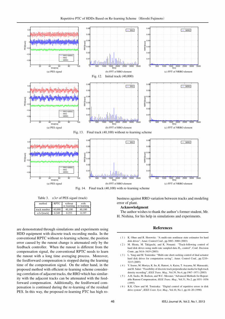
Position error signal, the RRO element and the NRRO ele-ment are shown in Fig. 12(a), Fig. 13(a) and Fig. 14(a), re-spectively. RRO and NRRO elements are displayed withintentional off-set to prevent overlapping. As shown inFig. 12(b), Fig. 13(b) and Fig. 14(b) which show the FFT ofPES caused by RRO, the RRO element under the cut-off fre-quency of Q filter is greatly suppressed. On the other hand,the RRO element in the frequency band in which the sensitiv-ity function has peak or over the cut-off frequency of Q filtercan not be suppressed. The FFT of PES caused by NRROis shown in Fig. 12(c), Fig. 13(c) and Fig. 14(c). As shownin Fig. 14.(c), the NRRO element of the proposed method isalmost the same with the others. Table 3 shows the ±3σ foreach case. As shown in this table, the proposed method at-tenuates the position error well. We can say that the proposedmethod improves the track-following performance.
5. Conclusion
In this paper, a novel re-learning scheme of the repeti-tive controller based on PTC is proposed and the advantages
45 IEEJ Journal IA, Vol.2, No.1, 2013
Repetitive PTC of HDDs Based on Re-learning Scheme(Hiroshi Fujimoto)
(a) PES signal (b) FFT of RRO element (c) FFT of NRRO element
Fig. 12. Initial track (40,000)
(a) PES signal (b) FFT of RRO element (c) FFT of NRRO element
Fig. 13. Final track (40,100) without re-learning scheme
(a) PES signal (b) FFT of RRO element (c) FFT of NRRO element
Fig. 14. Final track (40,100) with re-learning scheme
Table 3. ±3σ of PES siganl (track)
method RPTC without withre-learning re-learning
track number 40,000 40,100 40,100±3σ[track] 0.249 0.253 0.197
are demonstrated through simulations and experiments usingHDD equipment with discrete track recording media. In theconventional RPTC without re-learning scheme, the positionerror caused by the runout change is attenuated only by thefeedback controller. When the runout is different from thecompensation signal, the conventional RPTC needs to learnthe runout with a long time averaging process. Moreover,the feedforward compensation is stopped during the learningtime of the compensation signal. On the other hand, in theproposed method with efficient re-learning scheme consider-ing correlation of adjacent tracks, the RRO which has similar-ity with the adjacent tracks can be attenuated with the feed-forward compensation. Additionally, the feedforward com-pensation is continued during the re-learning of the residualPES. In this way, the proposed re-learning PTC has high ro-
bustness against RRO variation between tracks and modelingerror of plant.
AcknowledgmentThe author wishes to thank the author’s former student, Mr.
H. Nishina, for his help in simulations and experiments.
References
( 1 ) K. Ohno and R. Horowitz: “A multi-rate nonlinear state estimator for harddisk drives”, Amer. Control Conf., pp.3083–3088 (2003)
( 2 ) M. Hirata, M. Takiguchi, and K. Nonami: “Track-following control ofhard disk drives using multi-rate sampled-data H∞ control”, Conf. DecisionContr., pp.3414–3419 (2003)
( 3 ) L. Yang and M. Tomizuka: “Multi-rate short-seeking control of dual actuatorhard disk drives for computation saving”, Amer. Control Conf., pp.3210–3215 (2005)
( 4 ) Y. Soeno, M. Moriya, K. Ito, K. Hattori, A. Kaizu, T. Aoyama, M. Matsuzaki,and H. Sakai: “Feasibility of discrete track perpendicular media for high trackdensity recording”, IEEE Trans. Mag., Vol.39, No.4, pp.1967–1971 (2003)
( 5 ) A.H. Sacks, M. Bodson, and W.C. Messner, “Advanced Methods for Repeat-able Runout Compensation, IEEE Trans. Mag., Vol.31, No.2, pp.1031–1036(1995)
( 6 ) K.K. Chew and M. Tomizuka: “Digital control of repetitive errors in diskdrive system”, IEEE Contr. Syst. Mag., Vol.10, No.1, pp.16–20 (1990)
46 IEEJ Journal IA, Vol.2, No.1, 2013

Repetitive PTC of HDDs Based on Re-learning Scheme(Hiroshi Fujimoto)
( 7 ) T. Atsumi, A. Okuyama, and M. Kobayashi: “Track-following Control UsingResonant Filter in Hard Disk Drives”, Amer. Control Conf., pp.61–67 (2007)
( 8 ) H. Melkote, Z. Wang, and R.J. McNab: “An Iterative Learning Controllerfor Reduction of Repetitive Runout in Disk Drives”, IEEE Trans. Cont. Sys.Tech., Vol.14, No.3, pp.467–473 (2006)
( 9 ) M.R. Graham and R.A. de Callafon: “An Iterative Learning Design for Re-peatable Runout Cancellation in Disk Drives”, IEEE Trans. Cont. Sys. Tech.,Vol.14, No.3, pp.474–482 (2006)
(10) S.C. Wu and M. Tomizuka: “Novel Schemes for Repeatable Runout Com-pensation Using Adaptive Feedforward Cancellation”, Amer. Control Conf.,pp.43–48 (2007)
(11) C. Duan, G. Gu, C. Du, and T.C. Chong: “Robust Compensation of Peri-odic Disturbances by Multirate Control”, IEEE Trans. Mag., Vol.44, No.3,pp.413–418 (2008)
(12) H. Fujimoto and Y. Hori: “High Performance Servo Systems Based on Mul-tirate Sampling Control”, IFAC Journal on Control Engineering Practice,Vol.10, No.7, pp.773–781 (2002)
(13) H. Fujimoto: “RRO Compensation of Hard Disk Drives with MultirateRepetitive Perfect Tracking Control”, IEEE Trans. Industrial Electronics,Vol.56, No.10, pp.3825–3831 (2009)
(14) H. Fujimoto, Y. Hori, and A. Kawamura: “Perfect tracking control basedon multirate feedforward control with generalized sampling periods”, IEEETrans. Industrial Electronics, Vol.48, No.3, pp.636–644 (2001)
Hiroshi Fujimoto (Senior Member) received the Ph.D. degree in theDepartment of Electrical Engineering from the Uni-versity of Tokyo in 2001. In 2001, he joined the De-partment of Electrical Engineering, Nagaoka Univer-sity of Technology, Niigata, Japan, as a research asso-ciate. From 2002 to 2003, he was a visiting scholar inthe School of Mechanical Engineering, Purdue Uni-versity, U.S.A. In 2004, he joined the Department ofElectrical and Computer Engineering, Yokohama Na-tional University, Yokohama, Japan, as a lecturer and
he became an associate professor in 2005. He is currently an associate pro-fessor of the University of Tokyo since 2010. He received the Best Pa-per Award from the IEEE Transactions on Industrial Electronics in 2001,Isao Takahashi Power Electronics Award in 2010, and Best Author Prizeof SICE in 2010. His interests are in control engineering, motion control,nano-scale servo systems, electric vehicle control, and motor drive. Dr. Fuji-moto is a member of IEEE, the Society of Instrument and Control Engineers,the Robotics Society of Japan, and the Society of Automotive Engineers ofJapan.
47 IEEJ Journal IA, Vol.2, No.1, 2013