Embed Size (px)
Citation preview
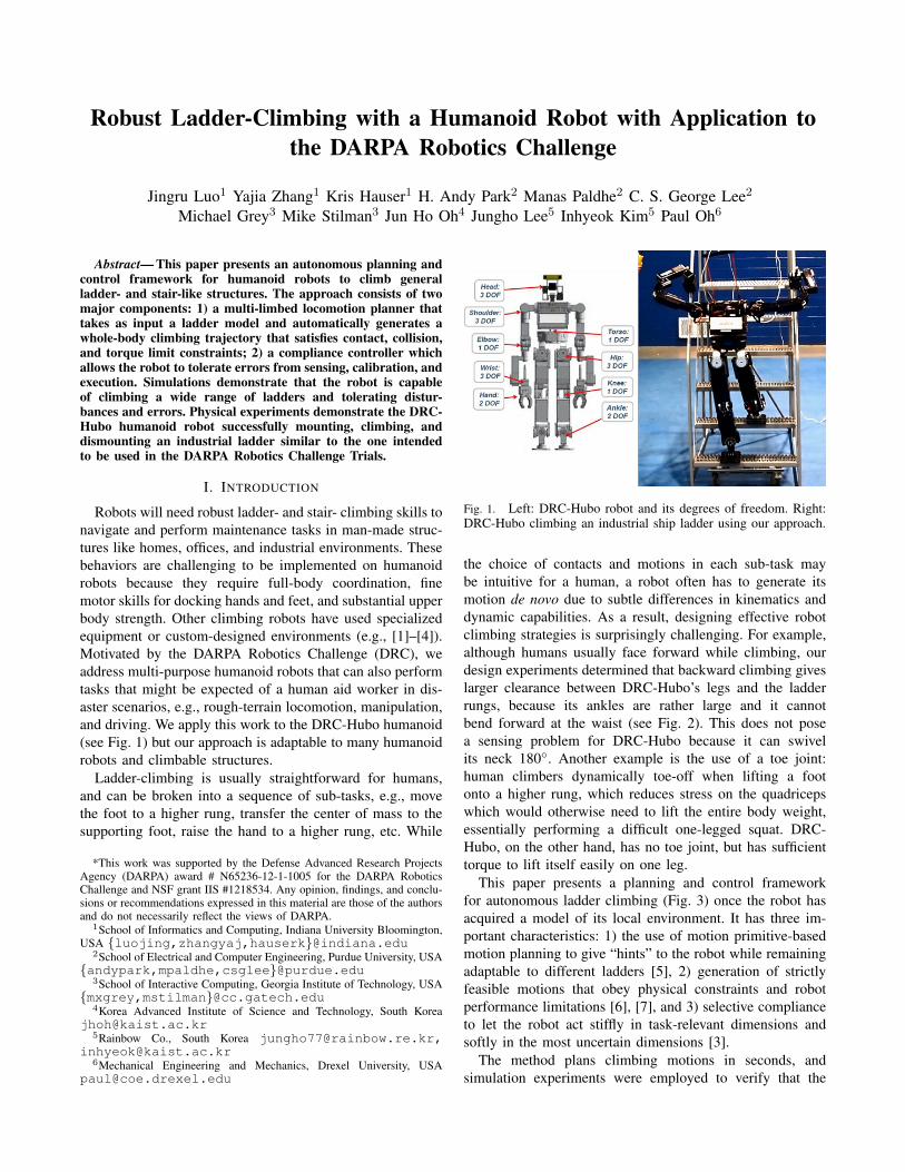
Robust Ladder-Climbing with a Humanoid Robot with Application tothe DARPA Robotics Challenge
Jingru Luo1 Yajia Zhang1 Kris Hauser1 H. Andy Park2 Manas Paldhe2 C. S. George Lee2
Michael Grey3 Mike Stilman3 Jun Ho Oh4 Jungho Lee5 Inhyeok Kim5 Paul Oh6
Abstract— This paper presents an autonomous planning andcontrol framework for humanoid robots to climb generalladder- and stair-like structures. The approach consists of twomajor components: 1) a multi-limbed locomotion planner thattakes as input a ladder model and automatically generates awhole-body climbing trajectory that satisfies contact, collision,and torque limit constraints; 2) a compliance controller whichallows the robot to tolerate errors from sensing, calibration, andexecution. Simulations demonstrate that the robot is capableof climbing a wide range of ladders and tolerating distur-bances and errors. Physical experiments demonstrate the DRC-Hubo humanoid robot successfully mounting, climbing, anddismounting an industrial ladder similar to the one intendedto be used in the DARPA Robotics Challenge Trials.
I. INTRODUCTION
Robots will need robust ladder- and stair- climbing skills tonavigate and perform maintenance tasks in man-made struc-tures like homes, offices, and industrial environments. Thesebehaviors are challenging to be implemented on humanoidrobots because they require full-body coordination, finemotor skills for docking hands and feet, and substantial upperbody strength. Other climbing robots have used specializedequipment or custom-designed environments (e.g., [1]–[4]).Motivated by the DARPA Robotics Challenge (DRC), weaddress multi-purpose humanoid robots that can also performtasks that might be expected of a human aid worker in dis-aster scenarios, e.g., rough-terrain locomotion, manipulation,and driving. We apply this work to the DRC-Hubo humanoid(see Fig. 1) but our approach is adaptable to many humanoidrobots and climbable structures.
Ladder-climbing is usually straightforward for humans,and can be broken into a sequence of sub-tasks, e.g., movethe foot to a higher rung, transfer the center of mass to thesupporting foot, raise the hand to a higher rung, etc. While
*This work was supported by the Defense Advanced Research ProjectsAgency (DARPA) award # N65236-12-1-1005 for the DARPA RoboticsChallenge and NSF grant IIS #1218534. Any opinion, findings, and conclu-sions or recommendations expressed in this material are those of the authorsand do not necessarily reflect the views of DARPA.
1School of Informatics and Computing, Indiana University Bloomington,USA {luojing,zhangyaj,hauserk}@indiana.edu
2School of Electrical and Computer Engineering, Purdue University, USA{andypark,mpaldhe,csglee}@purdue.edu
3School of Interactive Computing, Georgia Institute of Technology, USA{mxgrey,mstilman}@cc.gatech.edu
4Korea Advanced Institute of Science and Technology, South [email protected]
5Rainbow Co., South Korea [email protected],[email protected]
6Mechanical Engineering and Mechanics, Drexel University, [email protected]
Fig. 1. Left: DRC-Hubo robot and its degrees of freedom. Right:DRC-Hubo climbing an industrial ship ladder using our approach.
the choice of contacts and motions in each sub-task maybe intuitive for a human, a robot often has to generate itsmotion de novo due to subtle differences in kinematics anddynamic capabilities. As a result, designing effective robotclimbing strategies is surprisingly challenging. For example,although humans usually face forward while climbing, ourdesign experiments determined that backward climbing giveslarger clearance between DRC-Hubo’s legs and the ladderrungs, because its ankles are rather large and it cannotbend forward at the waist (see Fig. 2). This does not posea sensing problem for DRC-Hubo because it can swivelits neck 180◦. Another example is the use of a toe joint:human climbers dynamically toe-off when lifting a footonto a higher rung, which reduces stress on the quadricepswhich would otherwise need to lift the entire body weight,essentially performing a difficult one-legged squat. DRC-Hubo, on the other hand, has no toe joint, but has sufficienttorque to lift itself easily on one leg.
This paper presents a planning and control frameworkfor autonomous ladder climbing (Fig. 3) once the robot hasacquired a model of its local environment. It has three im-portant characteristics: 1) the use of motion primitive-basedmotion planning to give “hints” to the robot while remainingadaptable to different ladders [5], 2) generation of strictlyfeasible motions that obey physical constraints and robotperformance limitations [6], [7], and 3) selective complianceto let the robot act stiffly in task-relevant dimensions andsoftly in the most uncertain dimensions [3].
The method plans climbing motions in seconds, andsimulation experiments were employed to verify that the

Fig. 2. Comparison of different climbing strategies. Left: in forwardclimbing, the leg joints can easily collide with the rungs (the collidingjoints is drawn in yellow); Middle: in forward splayed-feet climbing, theleg clearance is improved but this strategy is not able to climb ladders nearvertical; Right: backward climbing provides the best leg joints clearance.
Ladder-Climbing Motion Planner Ladder Model/Specs
Robot Positioning w.r.t Ladder
Whole-body Trajectory • Collision-free • Quasi-statically Stable
Input:
Compliance Controller
Perception Module
DRC-Hubo Hardware
Output:
Joint Commands and Torque Commands
Fig. 3. Ladder-climbing framework. We assume a perceptionmodule (which is underdevelopment and not covered in this paper)provides the ladder environment as input to the ladder-climbingmotion planner. The planner generates a feasible trajectory for acompliant controller which enables compliance on arm joints forerror compensation.
robot can execute them successfully on a wide variety ofladders, including A-frame ladders, vertical ladders, and shipladders. The system is also relatively robust. Experimentson the physical robot suggest that errors in rail position betolerated as long as the rail is within the open fingers’ range,approximately ±5 cm left and right. Simulation experimentsalso suggest that errors of ±2 cm in rung spacing may betolerated in successful. Finally, we employed the system toenable the physical DRC-Hubo to climb up stairs whileholding handrails, and to mount, climb, dismount a shipladder similar to the ladder intended to be used in the DARPARobotics Challenge Trials in December 2013 [8].
II. INTEGRATED HARDWARE AND SOFTWAREFRAMEWORK
This section summarizes our integrated planning, control,and execution framework. The major components will bedescribed in more detail in later sections.
A. DRC-Hubo Robot
The DRC-Hubo humanoid is an upgraded version ofHubo-II+ built by Rainbow Co. for Team Hubo participatingin the DARPA Robotics Challenge. This robot is about140cm height and 50kg weight and has 33 degrees offreedom (DOFs): 7 in each arm, 6 in each leg, 1 in the waist,3 in the neck, 1 in each hand for controlling the opening
and closing and one extra for the trigger finger on the righthand(see Fig. 1).
The sensor head installed on DRC-Hubo contains a lidarand stereo cameras for perceiving the environment andproviding visual feedback. The robot is also equipped with3-axis F/T sensors on each wrist and ankle, accelerometersand gyros on the ankles and an inertia measurement unit forsensor feedback in motion execution. Two computer modulesare located in the chest; one for real-time whole-body controlthrough Controller Area Network (CAN), and the other forvision processing. In the current work, we do not use visionexcept to help a human operator pre-survey the ladder model.Work to integrate perception with planning is ongoing.
B. Ladder and Environment Modeling
The input to our system is a ladder model and relativepose of the ladder w.r.t. the robot. The output is raw motorcommands for the DRC-Hubo to execute. It supports awide variety of ladder models, including A-frame ladders,regular ladders, and ship ladders. The ladder specificationcontains an arbitrary number of stringers, rungs, and handrails. Parameters describe the ladder inclination, numberof rungs, rung spacing, rung width, rail height and cross-sectional geometries which can be circular or rectangular(Fig. 4). These models can be estimated in a number of ways,such as on-board perception, chosen by a human operator,or pre-surveyed from architectural blueprints. Obstacles likesupport rails or safety cages may also be incorporated intothe environment, and the planner will avoid collision withthese obstacles.
The framework also supports partially-known environ-ments. When the ladder is only partially in-view, the robotwill climb a user-specified number of steps, and replanningwill be invoked once it gets a better view. This capabilityis particularly useful when the top of the ladder and/ordismount area is occluded from the robot’s initial pose.
Fig. 4. Ladder models that can be addressed by our system. Left: a regularladder. Middle: an A-Frame ladder. Right: a ship ladder. Basic parametersshared by all ladders are marked on the regular ladder and special parametersfor A-Frame ladders and ship ladders are marked separately.
C. Motion Primitive-Based Planner
The planner takes the robot’s posture and environmentknowledge as input, and outputs a collision-free and quasi-statically stable joint-space trajectory. Motion primitives,

trajectories designed by human experts, provide the robotwith prior knowledge about how to solve the ladder climb-ing problems – where the limbs are placed, how to keepbalance, how to avoid collision with rungs, etc. Our planneradapts primitives to new ladders using a combination ofoptimization and sampling-based planning techniques [5]. Toensure reliable planning, it is important that the planner canbacktrack rather than commit to all of its choices, becausean early bad choice of contact can lead to stalled progresslater on. Surprisingly, the planner can solve a wide varietyof ladders quickly with only one primitive sequence.
Fig. 5. Illustration of motion planning process. Left: A motion prim-itive includes limb placement and waypoints information designedfor certain ladder. Middle: The motion planner first determinesthe limb placement in the new ladder, then performs a lineartransformation that transforms the existing motion primitive inconfiguration space to fit the new environment. Right: A sampling-base process is used to retract the collision section (drawn in red)to obtain a collision-free path.
D. Compliance Controller
The controller interpolates the planned trajectory andsends commands to the hardware for execution. Early exper-iments with DRC-Hubo showed that executing in open loopis problematic. Due to stiff closed kinematic chains, smallerrors in contact can cause excessive contradictory torqueson the joints, leading to motor damage and/or shutdown.We employ a compliance controller to remedy this problemthrough current-based torque control. Because DRC-Huboalready has passive compliance in its ankles we found thecompliance is only needed on the arms; as the robot closesits hand into a secure grip, it corrects errors on the handposition relative to the railings.
III. LADDER CLIMBING MOTION PLANNING
The motion primitive planning approach is a hybrid ofgait-based and sampling-based planners that blends the speedof gait-based techniques with the generality of sample-basedones [5]. Early work on motion planning for humanoid robotshave studied gait-based methods for footstep planning [9],integration of footstep planning and vision [10], and selec-tion of locomotion styles/postures to pass through narrowspaces [11]. These are most applicable to flat terrain withobstacles, and have limited applicability to highly variableterrain. More recent sampling-based techniques have allowedthe robot to generate motions on highly varied terrain byreasoning directly with motion constraints [12]. Since ladders
and stairs are semi-structured, it is reasonable to believe thata small number of predetermined gaits can be applied to newladders with a small amount of adaptation if the planner issufficiently powerful. Experiments in this paper confirm thisintuition.
A. Definitions of Motion Constraints
Balance, actuator constraints, and collision avoidance arecritical during climbing. The robot begins and ends on a twofoot stance, and during climbing, it makes contact with threeor four limbs. To model this, we introduce the concept of ahold to represent the overall contact of a single limb withthe environment. The feasibility of plan depends on both therobot’s configurations and contact state during the motion.
A hold includes multiple point-contacts r1, . . . , rk on therobot limb meeting x1, . . . , xk on the environment, and theircontact normals n1, . . . , nk and friction coefficients are usedto model the range of forces applicable to the environment(Fig. 6). In our implementation, we model a hand hold (withfingers) with eight point-contacts when the hand makes atight grasp on the rail (see Fig. 6 (a)); and the foot holdwith vertically-oriented point-contacts (see Fig. 6 (b)) at thecorners of the contact region (four on a rectangular rung andtwo on a cylindrical rung). A set of holds yields a stance σthat describes a contact state of the robot (Fig. 6 (c)).
Fig. 6. (a) Hand hold modeling (b) Foot hold modeling. Each hold includesa set of point-contacts, the contact normals and the friction cones. (c) Aconfiguration at the stance with two hands and two feet holds. Frictioncoefficient is assumed to be 0.25 in our example.
A configuration q at σ is defined as feasible iff it satisfiesall the following constraints:
1) Contact constraints: robot maintains the point-contactsspecified by all the holds in σ. This constraint restrictsthe motion to a lower-dimensional submanifold ofconfiguration space.
2) Joint limit constraints: q ∈ [qmin, qmax].3) Collision free with the robot itself and the environment.4) Quasi-static equilibrium: gravity balances the contact
forces respecting friction, torque and grip force limits.

A linear program is formulated to check if there existscontact forces (f1, . . . , fk) respecting force limits atthe given configuration q at stance σ for achieving bal-ance (a method similar to [13]), where f1, . . . , fk arethe contact forces for all the point-contacts r1, . . . , rkin σ respectively.
We define the feasible set of configurations at a stance asFσ = {q | q is feasible at σ}.
The planner outputs a continuous path of configurationsq(t) and stances σ(t) such that the configuration is alwaysfeasible at its given stance. Stance switches are assumed tooccur at discrete points in time.
B. Motion Primitives
The planner accepts two types of motion primitives, witheach motion primitive corresponding to a specific sub-task:
1) Limb transfer. Such primitives invoke one hold change:add or remove the contacts of one limb while keepingother holds unchanged. E.g., placing the hands on theladder from the standing pose will create new contactson the hands while keeping the contacts on the feetunchanged; moving the left foot onto a higher rungwill change its contacts to higher rung while keepingthe rest holds unchanged.
2) Center of mass (COM) transfer. These primitives trans-fer the COM position without changing the stance.E.g., before moving left foot onto a higher rung,the COM is transferred to the right foot to achievebalance. In our implementation, there are three motionprimitives for adjusting COM position, transfer COMto left/right foot before moving one foot, and transferCOM to the center of the two feet before releasinghand contacts.
Our implementation composes a ladder-climbing motionout of two motion primitive sequences, for a total of 9primitives (see Fig. 7). The first sequence (primitives 1–2in Fig. 7) mounts the ladder. The second executes a singleclimbing cycle of 7 primitives that ascends one rung (3-9 inFig. 7). Furthermore, motion primitives for dismounting aredesigned specially for different ladders according to the topplatform.
C. Motion Primitive Adaptation Planner
COM transfer tasks are relatively simple to plan, andsimply require checking for the existence of a linear COMtrajectory to the support foot. Limb transfer tasks are morecomplex because they require finding new contact positionsas well as configuration-space paths. Here we describe theprimitive-guided sampling-based planner in detail.
First, the planner samples hand and foot placements forlimb transfer primitives, incorporating the human designer’sknowledge from the motion primitives. Each such primitivedefines a seed hold representing the “ideal” set of point-contacts relative to the ladder model and the robot’s currentconfiguration. Given the starting stance σs, the ending stanceσe of current sub-task is generated by sampling a hold hdaround the seed hold for the moving limb while keeping the
rest holds unchanged. The transition stance is σt = σe−hd,which excludes the hold for the moving limb.
Second, the planner uses the discretized configurations ofthe motion primitive Q = (qs, q1, . . . , qk, qe) to generate afeasible configuration sequence Q = (qs, q1, . . . , qm, qe) thatsatisfy:
1) qs ∈ Fσs
2) q1, ..., qm ∈ Fσt
3) qe ∈ Fσe
To do so, it calculates an ending configuration qe byprojecting qe on to the contact constraints of Fσe using anumerical inverse kinematics (IK) solver. We use a Newton-Raphson technique with random restarts from increasinglyperturbed initial configuration qe. Perturbations help increasethe success rate by avoiding local minima for hard problems,while staying close to the seed qe. With each success-ful projection, collision is checked, and configurations thatcollide with the environment are retracted by solving anonlinear constrained optimization process, similar to theIterative Constraint Enforcement algorithm [13]. Algorithm1 describes the projection procedure. The iteration limit n isset to be 10 in our implementation.
Algorithm 1 Project a configuration q onto Fσfor i = 0, 1, . . . , n: do
q ← Solve-IK(q + perturb(i))if IK was successful: then
if q is collision free and stable: thenreturn q
if q has no self-collisions: thenif retract(q) succeeds and q is stable: then
return q
Finally, the intermediate configurations (q1, . . . , qk) of Qencode the waypoints for avoiding obstacles. Because theyare designed for a certain ladder, they need adjustment tothe new problem. We begin by performing a linear trans-formation that transforms Q to begin and end at the new(qs, qe) using a method similar to [5] (see Fig. 5). Again,perturbations are used to retract configurations that collidewith the environment. Once milestones (qs, q1, . . . , qk, qe)are obtained, a recursive Bezier projection technique is usedto smoothly interpolate between milestones while maintain-ing the contact constraints of Fσt
[14]. A final feasibilitycheck is then performed on the path.
The Motion Primitive Adaptation Planner is given by thefollowing pseudocode:Adapt-Primitive(Q, qs, σs)1. Sample ending stance σe from σs2. Calculate qe ∈ Fσe
(Algorithm 1)3. Linear transform Q according to (qs, qe)4. Utilize Q for generating milestone path Q5. Fine discretize Q and check feasibility
If any step fails, the algorithm returns failure; otherwise,it returns a feasible path for the sub-task.
Fig. 7. Motion primitive examples, with the final configuration of eachprimitive shown. From left to right, top to bottom: mountLH, mountRH,moveCOMtoRF, placeLF, moveCOMtoLF, placeRF, moveCOMtoCenter,placeLH and placeRH where L and R indicate left and right, H and Findicate hand and foot respectively.
D. Multi-Step Planning
To compose primitives together into an N -primitive climb-ing sequence, the planner performs a depth first search. Thisapproach allows the possibility of backtracking to revise aprior choice if the current move appears infeasible or hard.The recursive multi-step planning procedure is given by thefollowing pseudocode:MSP-Recurse(qi, σi)1. Get the next primitive Qi+1
2. For j = 0, . . . ,m :3. If Adapt-Primitive(Qi+1,qi,σi) succeeds:4. Let qi+1, σi+1 be the sampled endpoint.5. If i+ 1 = N , return the path leading to qi+1, σi+1.6. If MSP-Recurse(qi+1,σi+1) succeeds, return the path.7. Return failure
Since the motion planner sequentially plans each sub-task,the feasibility of one sub-task is affected by the endingconfiguration and stance of the last sub-task, which mayhave depended on the one before that, etc. The parameter mcontrols the amount of effort the planner gives to each sub-task before backtracking. At one extreme, m = 1 implementsa descent approach with random restarts, which gives uptoo quickly; at the other, the planner may get stuck with noprogress. In our tuning, we found the value m = 5 to havegood performance in general.
IV. TRAJECTORY EXECUTION VIA COMPLIANCECONTROL
Execution of motion on a physical robot is never perfect.Errors from calibration, modeling, control, and mechanicalslack result in the robot’s end-effectors being slightly mis-placed. Furthermore, there are always three or four limbsin contact with the environment which form multiple closedkinematic chains. In joint position control mode, DRC-Hubotends to use motors controllers with extremely high positiongains, but these high gains tend to result in an over-currentwhenever a closed kinematic chain is present, due to theaforementioned small errors. When a motor detects an over-current condition, the joint motor controller cuts off power
to the motor to prevent damage to itself and the system as awhole.
To solve this, we implement a passive compliance con-troller, which controls the pulse width modulation (PWM)directly on the motors to adjust output torque according to acompliant set of position gains. The PWM duty percentage Pis computed using eq. (1), where kP and kD are proportionaland differential gains; xd, xc, xc are the desired jointposition, current joint position and velocity respectively; fis the feedforward term which is intended for investigatinggravity compensation in future work.
P = kP · (xd − xc) + kD · (−xc) + f (1)
In the experiments, we keep kD and f as zeros and rely onthe internal friction to damp the motors. kP is used to adjustthe joint compliance.
We enabled compliance on the arm joints which are mainlyused for extra balance support. Leg joints are kept stiff tosupport the weight of the body. Passive compliance controlon the arms makes them compliant to tolerate errors. How-ever, without gravity compensation, compliant joints alsointroduce errors in the execution. We mitigate the executionerrors by tuning the compliance gains to control the levelof compliance. Forward kinematics implies that shoulder,elbow and wrist joint positions have decreasing effects onthe end-effector pose, so we set the compliance gains kP forarm joints to achieve an increasing level of compliance fromshoulder to wrist.
The compliance control is implemented on Hubo-ach, alow level controller based on the ACH Inter-Process Com-munication (IPC) library [15]–[17] developed specially forHubo robots.
V. EXPERIMENTS
This section tests the performance of our proposed sys-tem (see the video supplement). For all timing results, theplanning was carried out on an Intel Core i7 2.8 GHzmachine with 4GB RAM. Simulation results use a customsimulator based on the Open Dynamics Engine rigid bodysimulator, extended with robot sensor / controller simulationand improved collision handling.
A. Planning on a Variety of Ladders
Our motion planner has been tested with the DRC-Huborobot, as well as its earlier version Hubo-II+, on variousladders using computer simulations. Fig. 8 shows the robotclimbing three different ladders. The motions are generatedwithin approximately 10–15 s.
We also tested the capabilities of DRC-Hubo to climba range of ladders while varying two parameters: rungspacing in the range [20 cm,35 cm], and incline angle in therange [70◦, 90◦]. The motion primitive in this experimentis designed specifically for 80◦ with 25 cm inclination. Foreach ladder, we tested our motion planner by utilizing motionprimitives to generate motions for 2-step climbing (see Fig. 7for the utilized motion primitives). The planner was given a120 seconds cutoff planning time. Among all the 336 ladders,

Fig. 8. DRC-Hubo climbs different ladders of 30cm rung spacing inphysical simulation. The green shadow indicates the reference motion. (a)Climbing a regular ladder of 70-degree inclination. (b) Climbing a verticalladder. (c) Climbing an A-frame ladder of 60-degree inclination.
72% of them can be solved successfully (see Fig. 9). Dueto the geometry of the foot and ankle, the planner failed atrung spacings lower than 22 cm because the rung spacing isnot high enough to avoid collision between the ankle and thehigher rung. When the inclination is close to 90◦ and rungspacing is close to 35 cm, the possible reason of failure isthe set of motion primitives may not be easy to be adaptedto such ladders.
B. Motion Robustness and Error Toleration
We performed three robustness tests. In the first test, wetested the amount of modeling error tolerable by the handon the real robot. Experiments in open-loop mode showedfrequent arm motor shutdown due to excessive torque causedby control and calibration errors. With the compliant control,we perturbed the hand position increasingly such that itdeviates from the desired position for gripping the rail. Wefound that the hand pose can be adjusted to grip the rail aslong as the rail is within the grasping range of fingers.
Second, we tested in simulation whether the robot cancontinue the climbing motion when the rung spacing ishigher or lower than the planned value. On a ship ladderexample, we increase (reduce) the rung spacing 1 cm eachtime and run the planned trajectory in the changed scenario.The results show that the robot is able to tolerate such errorswith up 2 cm variation from the planned rung spacing. At3 cm, the robot’s foot slips from its intended placement onthe rung and the robot falls over.
In the final simulation test, we dropped an object on therobot during execution (see Fig. 10). Such disturbances mightoccur due to falling debris in disaster environments or undertrees. We gradually increased the weight of the object by5 kg increments, and the robot is able to withstand a 10kgimpact at speed 5.5m/s. At 15 kg, the robot is unable to holdonto the ladder and it falls.
C. Climbing a Ship Ladder on Physical Robot
Fig.11 demonstrates our system applied to a standardindustrial ship ladder that is similar to the one in DARPA’sspecifications “DRC Trials Initial Task Descriptions” for theDRC Trial [8]. The ladder has 5 rungs and a wide top
20
21
22
23
24
25
26
27
28
29
30
31
32
33
34
35
70 72 74 76 78 80 82 84 86 88 90
Planning Results on A List of Ladders
Inclination (degree)
Run
g S
paci
ng (c
m)
Student Version of MATLAB
Fig. 9. Testing on a range of ladder inclinations and rung spacings insimulation. Black indicates motion planner succeeded in planning the two-step climbing motion within 120 s cutoff time.
Fig. 10. Robustness test (a), (b) A ball of progressively increasing weightis dropped onto the robot at the speed of 5.5m/s. (c) The robot is able tocontinue the motion after hit by the ball of 10 kg. (d) The robot falls downafter hit by the ball of 15 kg.
for dismounting. It is 60◦ inclination, 80 cm rung width,17 cm rung depth, 25 cm rung spacing and 100 cm rail height.Planning completed in less than 15 seconds, and the climbingmotion successfully completes in 7 minutes. The robot is alsoable to climb back down the ladder simply by reversing themotion (not shown).
VI. CONCLUSION AND FUTURE WORK
This paper presented a planning and control framework forladder climbing humanoid that can be successfully appliedto a wide variety of ladders. The method integrates a motionprimitive-based motion planner with a compliant controller,and the resulting system is demonstrated to enable DRCHubo to successfully climb an industrial ladder.
Several issues remain for ongoing work. We are currentlyintegrating automated and human-assisted perception into thesystem via deformable model fitting, and we are investigatingmethods for detecting and correcting for larger executionerrors using visual or tactile feedback. Climbing is alsosomewhat slow because quasistatically-stable paths must beexecuted slowly to avoid dynamic effects, so we are investi-gating methods (e.g., [14]) to optimize execution times under

Fig. 11. Snapshots of DRC-Hubo mounting, climbing and dismounting the ship ladder.
dynamic constraints. Finally, we would like to improve theversatility of the planner to adapt to very different strategiesand scenarios. As an instance of the latter issue, note theplanner failed to solve for a vertical ladder with 35 cmrung spacing. We cannot tell whether the robot is physicallyincapable of climbing this ladder, or the primitive was noteasy enough to adapt. Future implementations may use largeprimitives libraries and dynamically select appropriate onesfor the given environment.
REFERENCES
[1] H. lida, H. Hozumi, and R. Nakayama, “Development of LadderClimbing Robot LCR-1,” J. Robotics and Mechatronics, vol. 1, no. 4,pp. 311–316, 1989.
[2] D. Bevly, S. Farritor, and S. Dubowsky, “Action module planning andits application to an experimental climbing robot,” in IEEE Int. Conf.Robot. Autom., vol. 4, 2000, pp. 4009–4014 vol.4.
[3] S. Kim, M. Spenko, S. Trujillo, B. Heyneman, V. Mattoli, andM. Cutkosky, “Whole body adhesion: hierarchical, directional anddistributed control of adhesive forces for a climbing robot,” in IEEEInt. Conf. Robot. Autom., Apr. 2007, pp. 1268–1273.
[4] H. Yoneda, K. Sekiyama, Y. Hasegawa, and T. Fukuda, “Vertical ladderclimbing motion with posture control for multi-locomotion robot,” inIEEE/RSJ Int. Conf. Intell. Robot. Sys., Sept. 2008, pp. 3579–3584.
[5] K. Hauser, T. Bretl, K. Harada, and J.-C. Latombe, “Using mo-tion primitives in probabilistic sample-based planning for humanoidrobots,” in Workshop on the Algorithmic Foundations of Robotics,2006.
[6] T. Bretl, S. Lall, J.-C. Latombe, and S. Rock, “Multi-step motionplanning for free-climbing robots,” in Workshop on the AlgorithmicFoundations of Robotics, 2004.
[7] T. Bretl, “Multi-step motion planning: Application to free-climbingrobots,” PhD Thesis, Stanford University, June 2005.
[8] (2013) The darpa robotics challenge website. [Online]. Available:http://www.theroboticschallenge.org
[9] J. J. Kuffner, S. Kagami, K. Nishiwaki, M. Inaba, and H. In-oue, “Dynamically-stable motion planning for humanoid robots,”Autonomous Robots, vol. 12, pp. 105–118, 2002.
[10] S. Kagami, K. Nishiwaki, J. Kuffner, K. Okada, M. Inaba, and H. In-oue, “Vision-based 2.5D terrain modeling for humanoid locomotion,”in IEEE Int. Conf. Robot. Autom., vol. 2, Sept. 2003, pp. 2141–2146.
[11] F. Kanehiro, H. Hirukawa, K. Kaneko, S. Kajita, K. Fujiwara,K. Harada, and K. Yokoi, “Locomotion planning of humanoid robotsto pass through narrow spaces,” in IEEE Int. Conf. Robot. Autom.,vol. 1, 2004, pp. 604–609.
[12] K. Hauser, T. Bretl, J.-C. Latombe, K. Harada, and B. Wilcox, “Motionplanning for legged robots on varied terrain,” Robotics: Science andSystems, vol. 27, no. 11-12, pp. 1325–1349, Dec. 2008.
[13] K. Hauser, T. Bretl, and J.-C. Latombe, “Non-gaited humanoid loco-motion planning,” in IEEE Int. Conf. on Humanoid Robots, Dec. 2005,pp. 7–12.
[14] K. Hauser, “Fast interpolation and time-optimization on implicitcontact submanifolds,” in Robotics: Science and Systems, Berlin,Germany, June 2013.
[15] N. Dantam and M. Stilman, “Robust and efficient communicationfor real-time multi-process robot software,” in IEEE Int. Conf. onHumanoid Robots, 2012, pp. 316–322.
[16] M. Grey, N. Dantam, D. Lofaro, A. Bobick, M. Egerstedt, P. Oh, andM. Stilman, “Multi-process control software for hubo2 plus robot,”in Proc. Int. Conf. on Technologies for Practical Robot Applications(TePRA), 2013, pp. 1–6.
[17] D. Lofaro, “Unified algorithmic framework for high degree of freedomcomplex systems and humanoid robots,” Ph.D. dissertation, DrexelUniversity, College of Engineering, Electrical and Computer Engi-neering Department, May 2013.
![Motion Planning of Ladder Climbing for Humanoid Robots 2017. 2. 6. · (OpenRAVE) [16], an open-source planning and simulation framework. OpenRAVE is widely used in the robotics com](https://img.pdfslide.us/doc/110x75/601f199cdc3a010e632ba7fb/motion-planning-of-ladder-climbing-for-humanoid-2017-2-6-openrave-16-an.jpg)