Embed Size (px)
Citation preview
1
Robust functionalization of graphene for organic electrode
materials
March 2021
Rizwan Khan
Graduate School of Natural Science and Technology
(Doctor Course)
Okayama University
2
Two-dimensional nanocarbons, as represented by graphene, have been the subject of active
research owing to their outstanding physical properties, such as toughness, high specific
surface area, and high electrical and thermal conductivities. As the physical properties of
graphene and its analogs have mostly been elucidated by intense research over more than 15
years, the development of functionalization methods to further enhance their
physical/chemical properties is in great demand. Particularly, graphene oxide (GO) brings
unique chemical reactivity. This is mainly due to the large amounts of reactive epoxy,
hydroxyl, and carboxyl groups. These oxygenated groups provide the possibility of
covalently grafting functional molecules onto GO sheets in high grafting density by using
various organic reactions.
The present study aims to robust functionalization of graphene and their applications for
organic electrodes. This thesis is divided into six chapters. The first two chapter is consisting
of introduction.
Chapter 1 presents a comprehensive literature review of graphene is given. Initially, various
graphene synthesis methods are introduced. Then the functionalization of graphene, GO, and
reduced graphene oxide (RGO) and classification between covalent and non-covalent
functionalization are explained. The covalent functionalization was discussed in detail.
Chapter 2 describes various functionalization routes of graphene with redox-active materials
(small molecules and polymers) and their application for lithium-ion batteries (LIBs) and
supercapacitors (SCs) were discussed.
The next three chapters of this thesis report major scientific advances achieved through this
study; they all detail robust functionalization of graphene and applications for energy
storage systems as given below.
In chapter 3, a new concept for graphene functionalization using brominated graphene has
been developed, in which brominated graphene is successfully functionalized by heteroatom-
containing molecules to form onium bonds, such as pyridinium or ammonium. The
counterion bromide is replaced with other anions, such as sulfate, by treating with sulfuric

3
acid while retaining the molecules, which demonstrates the durable properties of onium
bonding. To emphasize the advantages of this strategy for graphene functionalization, the
performance for energy-related applications, such as biofuel cells, SCs, and LIBs, is
evaluated after introducing redox-active moieties onto graphene through onium bonding.
Among applications such as the LIBs, SCs, and biofuel cell, the SCs was found to be
promising.
In chapter 4, a three-step reaction furnished a composite of graphene and a conductive
polymer. In the first step, GO was modified with a diamine, which acted as a linker for
polymer attachment. In the second step, an initiating site was attached to the free amine of
the linker. Finally, a polymer was grown from the initiation site, and GO was reduced during
polymer growth. The method does not require any catalyst, acid, or reducing agent,
furnishing the graphene–polymer composite in a straightforward procedure. The electrical
properties of the composite were evaluated to determine its suitability as an electrode material
for a SCs. The covalent cross-linked polymer-graphene composite demonstrated a high
capacitance and good cycling stability than non-crosslinked graphene–polymer mixture. This
method of functionalization provides a guideline in the future for the preparation of another
graphene–polymer-based composites.
In chapter 5, a series of organic molecules was functionalized on GO by using stepwise
covalent double functionalization method. The first step consists of ring-opening reaction of
epoxide group by amine compounds. The mono functionalized GO, containing more OH
groups compared to pristine GO, was modified with α,β-unsaturated carbonyl compounds
via Michael reaction. The role of double functionalization was studied in proton conductivity
and SCs. The proton conductivity of double functionalized GO was improved by tuning the
surface functional groups of GO. Similarly, the SCs performance of the double functionalized
GO was improved by introducing redox-active molecules.
Chapter 6 present the final conclusion.

4
Contents
Chapter 1 synthesis, functionalization and characterization of graphene, GO and
RGO ………………………………………………………………………………… 6
Conclusion ………………………………………………………………………….. 35
References …………………………………………………………………………... 37
Chapter 2 covalent functionalization of graphene with redox-active molecules for
energy storage ……………………………………………………………………… 40
Conclusion and challenges ………………………………………………………….. 57
References …………………………………………………………………………... 59
Chapter 3 a simple and robust functionalization of graphene for advanced energy
devices ……………………………………………………………………………… 65
Abstract …………………………………………………………………………….. 67
Introduction ………………………………………………………………………… 67
Result and discussion ………………………………………………………………. 69
Conclusion …………………………………………………………………………. 85
Experimental section ………………………………………………………………. 86
References …………………………………………………………………………. 91
Chapter 4 grafting conductive polymers on graphene oxide through cross-linker: a
stepwise approach ………………………………………………………………. 94
Abstract …………………………………………………………………………… 96
Introduction ………………………………………………………………………. 96
Result and discussion …………………………………………………………...... 98
Conclusion ……………………………………………………………………….. 114
Experimental section …………………………………………………………….. 115
References ……………………………………………………………………….. 118
Chapter 5 Covalent double functionalization enables multi-function and enhanced
performances ……………………………………………………………………. 121

5
Abstract ………………………………………………………………………….. 123
Introduction ……………………………………………………………………… 123
Result and discussion ……………………………………………………………. 124
Conclusion ………………………………………………………………………. 143
Experimental section ……………………………………………………………. 143
References ………………………………………………………………………. 146
Chapter 6 Final conclusion ……………………………………………………. 149
List of abbreviation ……………………………………………………………… 163
List of publication ………………………………………………………………. 165
Dedication ………………………………………………………………………. 166
Acknowledgement ……………………………………………………………… 167

6
Chapter 1
Synthesis, functionalization and characterization of
graphene, GO and RGO

7
Introduction …………………………………………………………………………. 9
1.1. Synthesis of graphene ……………………………………………………….. 10
1.1.1. Mechanical exfoliation …………………………………………………… 11
1.1.2. Ultrasonic cleavage ………………………………………………………. 11
1.1.3. CVD method ……………………………………………………………... 12
1.1.4. Epitaxial growth on SiC ………………………………………………….. 12
1.1.5. Unzipping of carbon nanotube ……………………………………………. 13
1.2. Physical properties of graphene ……………………………………………... 13
1.3. Chemical functionalization methods of graphene …………………………… 14
1.3.1. Functionalization through physical interaction …………………………… 14
1.3.2. Covalent functionalization reaction ……………………………………….. 15
1.3.2.1. Free radical addition reactions ……………………………………………. 15
1.3.2.1.1. Aryldiazonium salt ……………………………………………………. 16
1.3.2.1.2. Bergman cyclization ………………………………………………….. 16
1.3.2.1.3. Kolbe electrosynthesis ………………………………………………... 17
1.3.2.2. Nucleophilic addition reactions ………………………………………….. 18
1.3.2.3. Reaction with atomic radicals ……………………………………………. 18
1.3.2.4. Electrophilic substitution reactions ………………………………………. 19
1.3.2.5. Cycloaddition reactions …………………………………………………... 20
1.3.2.5.1. [2 + 1] cycloaddition ………………………………………………….. 20
1.3.2.5.1.1.Bingel reaction ………………………………………………………... 20
1.3.2.5.1.2.Aziridine adduct ………………………………………………………. 21
1.3.2.5.2. [2 + 2] cycloaddition ………………………………………………….. 22
1.3.2.5.3. [3 + 2] cycloaddition ………………………………………………….. 23
1.3.2.5.4. [4 + 2] cycloaddition ………………………………………………….. 24
1.4. Structure and properties of graphene oxide (GO) ……………………………. 24
1.4.1. Synthesis of GO …………………………………………………………… 25
1.4.2. Covalent functionalization reactions ……………………………………… 26
1.4.2.1. Functionalization of GO through hydroxyl groups ……………………… 26

8
1.4.2.2. Functionalization of GO through carboxylic acids ……………………… 28
1.4.2.3. Functionalization of GO through epoxides ……………………………… 29
1.4.3. Non-covalent functionalization reactions ………………………………... 29
1.5. Synthesis of reduced graphene oxide (RGO) …..……………………………. 29
1.5.1. Covalent Functionalization of RGO ……………………………………... 30
1.5.2. Non-covalent Functionalization Reactions of rGO ……………………… 30
1.6. Characterization …………………………………………………………….. 30
1.6.1. Fourier transform infrared Spectroscopy ………………………………... 31
1.6.2. Raman spectroscopy …………………………………………………….. 31
1.6.3. X-Ray photoelectron spectroscopy ……………………………………… 32
1.6.4. Thermogravimetric Analysis ……………………………………………. 33
1.6.5. Scanning Electron Microscopy ………………………………………….. 34
1.6.6. Atomic Force Microscopy ………………………………………………. 35
1.7. Conclusion ………………………………………………………………….. 35
1.8. References ………………………………………………………………….. 37

9
1. Introduction Carbon-based materials have extensively investigated due to their abundance,
processability, stability, and relatively environmentally friendly characteristics.1–3 Carbon-
based materials exist in different allotropic form such as 0-D fullerenes, 1-D carbon
nanotubes (single-walled carbon nanotubes (SWCNT), multi-walled carbon nanotubes
(MWCNT), 1D), 2-D graphene, 3-D diamond and 3-D graphite, having different physical
and chemical properties from each other. The advents of sp2 and/or sp3 hybridized structures,
such as CNTs, conducting diamond and fullerenes offer a route for surface functionalization
and are very promising for electrochemical research, especially electrocatalysis4 and
electrode materials.5 Diamond and graphite have been known and extensively studied for
centuries whereas nanotubes and fullerenes have been only discovered and investigated in
the last two decades.6,7 It is possible to think that graphite, nanotubes and fullerenes, as
different structures built from the same hexagonal array of sp2 carbon atoms, namely,
graphene (Figure 1).8 Among the other carbon-based materials , graphene emerged as an
attractive candidate for variety of applications due to its unique structure and properties.9
Surface modification of graphene result in variety of composites with unique properties.10
Therefore, researchers have developed various covalent and noncovalent functionalization
methods of graphene for variety of applications. Graphene is a one-atom-thick planar sheet
of sp2-bonded carbon atoms densely packed in a honeycomb crystal lattice. Naturally
occurring graphite has been known as a mineral for nearly 500 years. Graphene, the building
block of graphite, was theoretically established in 1940. Boehm and co-workers separated
thin lamellae of carbon by heating and chemical reduction of graphite oxide in 1962.11
However, until 2004, single-layer graphene was believed to be thermodynamically unstable
under ambient conditions. Geim and co-workers first identified single layers of graphene in
2004.12 This finding has provided a new dimension of research in the fields of chemistry,
physics, biotechnology and materials science.

10
Figure 1: Different Carbon-based materials originate from graphene
The ‘‘thinnest’’ known material graphene shows excellent electrical conductivity, thermal
conductivity, optical transparency, mechanical flexibility and low coefficient of thermal
expansion behavior.13 Graphene crystal, consisting of sp2 carbon framework, exists in thin
sheets. These carbon sheets can be produced in different forms such as monolayers, bilayers,
or up to three layers of graphene or GO.
1.1. Synthesis of graphene
Several synthetic methods for graphene have been reported in the literature. These
methods include exfoliation and cleavage of natural graphite, chemical vapor deposition
(CVD), epitaxial growth on electrically insulating surfaces such as silicon carbide (SiC) and
un-zipping of CNTs.
11
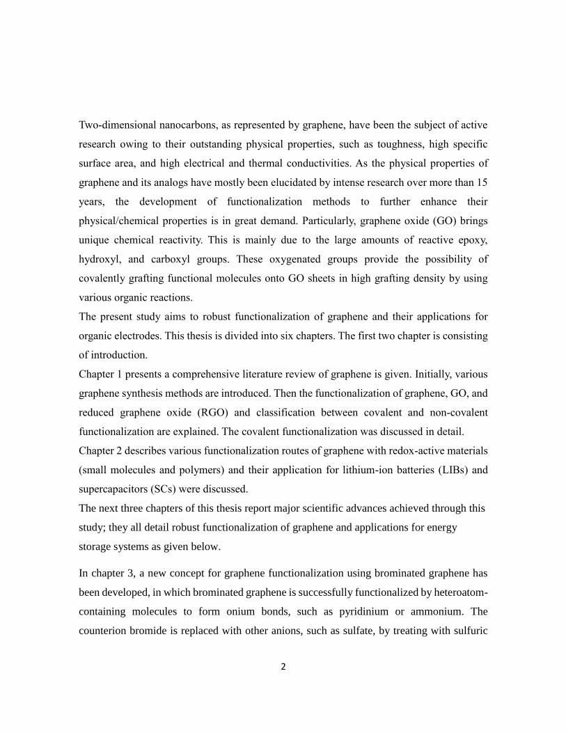
1.1.1. Mechanical exfoliation
In 2004, single layer graphene was isolated from few layered graphite through
mechanical exfoliation. In this approach, bulk graphite was bonded onto borosilicate glass
under a fixed condition and then remove leaving behind a single-layer or few-layer graphene
sheets on the substrate (Figure 2). It is very difficult to scale up this process.14
Figure 2: Synthesis of graphene through mechanical exploitation method
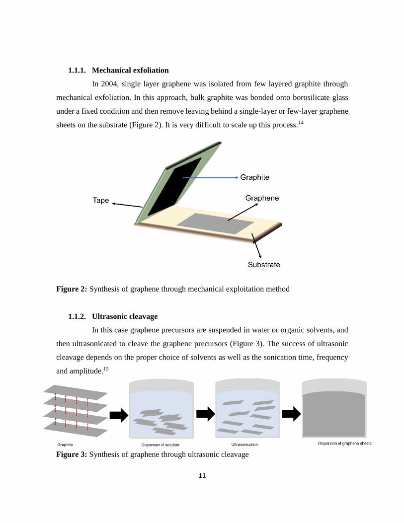
1.1.2. Ultrasonic cleavage
In this case graphene precursors are suspended in water or organic solvents, and
then ultrasonicated to cleave the graphene precursors (Figure 3). The success of ultrasonic
cleavage depends on the proper choice of solvents as well as the sonication time, frequency
and amplitude.15
Figure 3: Synthesis of graphene through ultrasonic cleavage
12
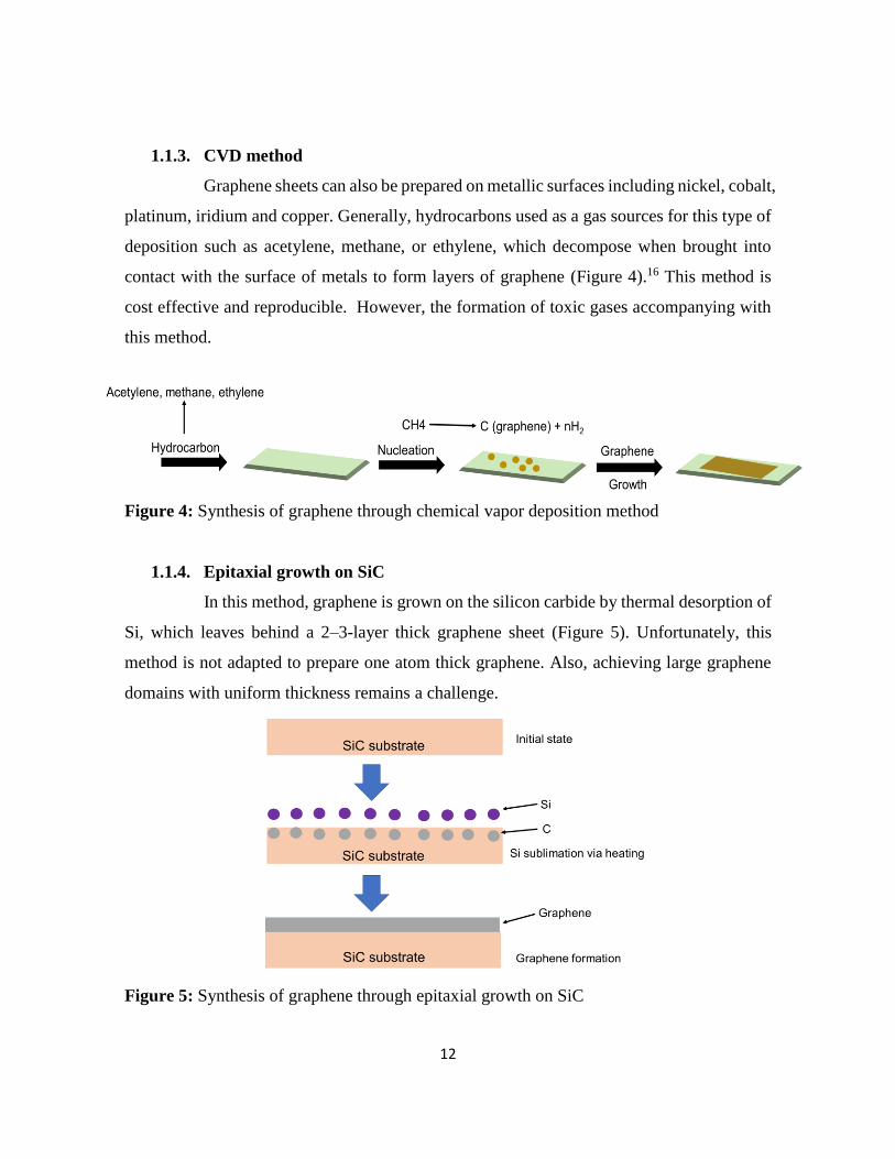
1.1.3. CVD method
Graphene sheets can also be prepared on metallic surfaces including nickel, cobalt,
platinum, iridium and copper. Generally, hydrocarbons used as a gas sources for this type of
deposition such as acetylene, methane, or ethylene, which decompose when brought into
contact with the surface of metals to form layers of graphene (Figure 4).16 This method is
cost effective and reproducible. However, the formation of toxic gases accompanying with
this method.
Figure 4: Synthesis of graphene through chemical vapor deposition method
1.1.4. Epitaxial growth on SiC
In this method, graphene is grown on the silicon carbide by thermal desorption of
Si, which leaves behind a 2–3-layer thick graphene sheet (Figure 5). Unfortunately, this
method is not adapted to prepare one atom thick graphene. Also, achieving large graphene
domains with uniform thickness remains a challenge.
Figure 5: Synthesis of graphene through epitaxial growth on SiC

13
1.1.5. Unzipping of CNT
Graphene sheets can be prepared by unzipping of CNTs. In this process, NH3-
solvated Li+ is simultaneous intercalated into MWCNTs, allowing unwrapping and
exfoliation.17 Another unzipping approach to use strong oxidizing agents.18 Alternative safe
method is the use of Ar plasma etching method to unzip MWCNTs (Figure 6).
Figure 6: Synthesis of graphene through unzipping of CNT
1.2. Physical properties of graphene
Graphene is an allotrope of carbon in which each carbon atom is bonded with another
carbon by sp2 bonds. The carbon atoms are bonded in a honeycomb crystal lattice with a
bond length of 0.14 nm.19 Different research groups have measured the thickness of graphene
from 0.35 nm to 1.00 nm.20 Graphene displays high intrinsic strength (130 GPa) and Young’s
modulus (1.00 TPa), making it the strongest material. Further, it can be stretched to
deformations well beyond the linear regime. The thermal conductivity of graphene at room
temperature can reach 5000 W m-1 K-1.21 Graphene shows very high surface area of 2600 m2
g-1, much larger than the surface areas of graphite of 0.60 m2 g-1 and CNTs of 1300 m2 g-1.22
The physical properties is summarized in Table 1. These remarkable properties make
graphene promising in applications such as polymer-composite materials, paper-like
materials, photo-electronics, electromechanical systems, field effect transistors, sensors and
electrochemical energy systems etc.23

14
Table 1: Physical properties of graphene as a material (experimental and theoretical)21
Bond length 0.14 nm
Thickness of single layer 0.35 nm to 1.00 nm
Intrinsic strength 130 GPa
Young’s modulus 1.00 TPa
Thermal conductivity 5000 W m-1 K-1
Surface area 2630 m2 g-1
Band gap zero
1.3. Chemical functionalization methods of graphene
Graphene is aromatic in nature possessing highly electronic density both above and
below the plane. The frontier molecular orbitals of organic molecules can easily interact with
the p-electrons of graphene. Therefore, electrophilic substitution of graphene is much easier
than nucleophilic substitution. The edges of graphene shows higher chemical reactivity than
arm-chair edges; because the aromatic sextets are perturbed in the zig-zag edges, leading to
thermodynamic instability.24
Graphene sheets can restack easily through π–π stacking and van der Waals interactions if
the sheets are not well separated from each other. Chemical modification of graphene through
covalent, non-covalent and ionic interaction avoids the aggregation of graphene sheets.25
Further, organic functional groups introduce new properties that could be improve the
properties of graphene. Therefore, the researcher has been focused on the development of
new surface functionalization method of graphene, with aim of exploiting the most frequently
proposed applications of graphene in the field of chemistry, physics and biology.
1.3.1. Functionalization through physical interaction
Graphene can be functionalized through physical interactions such as electrostatic
interactions, hydrophobic and van der Waals interactions, without disturbing the electronic
network in an easy and reversible way (Figure 7). The non-covalent functionalization is

15
playing a key role for the immobilization of organic molecules, particularly in electronic
devices as a little modification in the electronic characteristics of the π system can lead to
change the entire structure and properties of the system. The non-covalent interaction of
graphene has been extensively investigated and classified in non-polar π–π, gas–π, H–π,
anion–π and cation–π interaction.26 The strength of these interactions is a combination of
different forces that include electrostatic forces, inductive interactions, dispersive forces, and
exchange repulsion as repulsive forces. Non-covalent interaction is simple and easy to
prepared. However, these interactions are weak and molecular dissociation occurs easily.
Figure 7: Functionalization of graphene through non-covalent and ionic bonding
1.3.2. Covalent functionalization reaction
In contrast to physical interaction, the covalent interaction is strong and stable. Covalent
functionalization of graphene can be achieved through various organic reaction, which are
given below.
1.3.2.1. Free Radical Addition Reactions
Free radicals are highly reactive organic species toward the aromatic structure of
graphene to form covalent bonds. This functionalization has been achieved by chemical,
thermal and photochemical treatments. Graphene has been functionalized through different
free radical reaction such as aryl diazonium salts or peroxides such as Bergman cyclization
and the Kolbe electrosynthesis.

16
1.3.2.1.1. Aryl diazonium salts
Surface modification of carbon-based materials with diazonium chemistry has
been achieved initially by an isolated diazonium salt and later by in situ-generated one.
Although diazonium salt is unstable, it can be easily synthesized with an amine and NaNO2
in an acidic aqueous solution, tert-butyl nitrite, or NOBF4. Diazonium salt generates a radical
with the elimination of nitrogen, then covalently reacts with graphene (Figure 8). The radical
formation can be initiated by electrochemical, thermal, or pH-dependent methods.
Diazonium salts are important intermediates in organic chemistry, thus their derivatives are
widely available.27
Figure 8: Functionalization of graphene through diazonium chemistry
1.3.2.1.2. Bergman cyclization.
The Bergman cyclization introduced six-member ring on sp2 carbon network
of graphene. The reaction proceeds through a radical mechanism. The starting materials
consist of an ene-diyne moiety which undergoes cyclization at high temperature. The
cyclization results in the formation of 1,4-bezenediyl biradical species. The highly reactive
biradical species reacts with the graphene sp2carbon network through one side of the biradical
species. The other radical end could potentially available for other reaction such as hydrogen
abstraction or polymerization (Figure 9). Ma and coworker functionalized graphene with
polymer through Bergman cyclization.28
17
Figure 9: Functionalization of graphene through Bergman cyclization
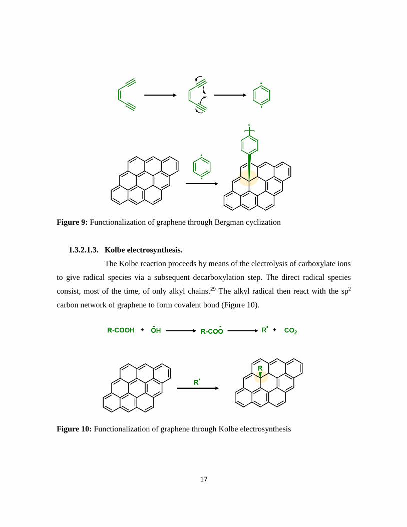
1.3.2.1.3. Kolbe electrosynthesis.
The Kolbe reaction proceeds by means of the electrolysis of carboxylate ions
to give radical species via a subsequent decarboxylation step. The direct radical species
consist, most of the time, of only alkyl chains.29 The alkyl radical then react with the sp2
carbon network of graphene to form covalent bond (Figure 10).
Figure 10: Functionalization of graphene through Kolbe electrosynthesis

18
1.3.2.2. Nucleophilic Addition Reactions
In a nucleophilic addition, graphene acts as an electron acceptor. The anionic
moiety is formed by using a base, leading to the generation of nitrogen anions on carbazole.
Subsequently, the anion reacts on the surface of graphene with the creation of a covalent
bond (Figure 11). Xu et al. grafted polymer on graphene through nucleophilic addition
reaction.30
Figure 11: Functionalization of graphene through nucleophilic addition reaction
1.3.2.3. Reaction with Atomic Radicals
Graphene has been functionalized with atomic radicals such as hydrogen,
fluorine and oxygen, with minimized possibility of side reactions. Atomic hydrogen reacts
with graphene, lead to the formation of graphene (Figure 12a).31 The total hydrogenated form
of graphene is called graphane. The halogenation (F, Cl, Br, I) of graphene is similar to the
hydrogenation (Figure 12b). Halogenated graphene allowing further transformation of
graphene for variety of applications. Among the halogenated graphene, fluorinated graphene
is extensively investigated for different applications. There are three main methods to
produce it: (i) by etching using fluorinated compound (ii) by exposition to XeF2, and (iii) by
liquid phase exfoliation of bulk graphite fluoride.32 The common method for the oxidation
of graphene is hummer method.33 The oxygenation of graphene through this method is
inhomogeneous. Oxygen radical lead to the formation of epoxide group on graphene (Figure
12c). The formation of epoxide groups has been obtained by exposing graphene at atomic
oxygen beams and oxygen plasmas.

19
Figure 12: Functionalization of graphene through atomic radical
1.3.2.4. Electrophilic Substitution Reactions
Graphene can be functionalized by electrophilic substitution reaction due to its
electron-rich nature. Examples of substitution reactions are the hydrogen–lithium exchange
and Friedel–Crafts acylation. In hydrogen-lithium exchange reaction, first the
carbometallation of graphene by butyl lithium, followed by the attachment of electrophile
(Figure 13a).34 The electrophile attach to the graphene by the elimination of lithium
metal.The ketone moieties can be introduced to graphene by Friedel–Crafts acylation. The
Lewis acid form the reactive intermediate (acyl cation), which proceed the reaction (Figure
13b).35

20
Figure 13: Functionalization of graphene through electrophilic substitution reactions
1.3.2.5. Cycloaddition Reactions
Four major types of cycloaddition introduced in the functionalization of graphene
sp2 carbon network: [2+1], [2+2], [3+2] and [4+2].
1.3.2.5.1. [2 + 1] cycloaddition.
This cycloaddition includes the Bingel reaction and reactions with nitrenes to
form cyclopropane or aziridine adducts, respectively.
1.3.2.5.1.1. Bingel reaction.
This reaction can be performed in mild conditions. The base subtracts a
proton, as a result the formation of enolate occurs, which attacks the C=C bond of graphene.
The carbanion undergoes a nucleophilic substitution reaction with the elimination of the

21
halide to form a three-member ring on graphene (Figure 14). Single layer graphene has been
functionalized through this reaction.36
Figure 14: Functionalization of graphene through Bingel reactions
1.3.2.5.1.2. Aziridine adduct.
The introduction of aziridine adduct onto the graphene network is usually
obtained via a nitrene intermediate. The nitrene intermediate is usually generated from a
thermal- or photodecomposition of an azide group, in the form of gaseous nitrogen molecule,
which is the most stable leaving group. This phenomenon generated highly reactive singlet
nitrene which subsequently undergoes a cycloaddition reaction on the graphene sp2 carbon
network to provide an aziridine adduct (Figure 15).37,38 Kim and co-workers were first to
perform this reaction on graphene in 2009.

22
Figure 15: Functionalization of graphene through aziridine adduct
1.3.2.5.2. [2 + 2] cycloaddition.
The formation of four-member ring on graphene sp2 carbon network goes
through an aryne or benzyne intermediate via an elimination–addition mechanism. The
presence of a fluoride ion induced a desilylation step to provide a carbanion with a filled sp2
orbital in the plane of the ring. This proceeded by an elimination of the triflate group to give
benzyne, which is electrophilic. Subsequent nucleophilic attack of benzyne on graphene
carbon network resulted in a [2 + 2] cycloaddition (Figure 16).39 The functionalization of
graphene based on the benzyne cycloaddition method discussed above was demonstrated by
Ma and co-worker.
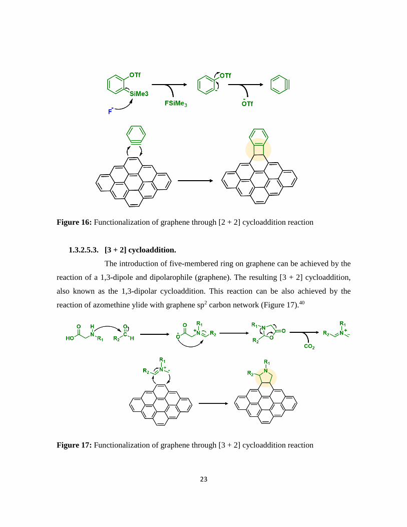
23
Figure 16: Functionalization of graphene through [2 + 2] cycloaddition reaction
1.3.2.5.3. [3 + 2] cycloaddition.
The introduction of five-membered ring on graphene can be achieved by the
reaction of a 1,3-dipole and dipolarophile (graphene). The resulting [3 + 2] cycloaddition,
also known as the 1,3-dipolar cycloaddition. This reaction can be also achieved by the
reaction of azomethine ylide with graphene sp2 carbon network (Figure 17).40
Figure 17: Functionalization of graphene through [3 + 2] cycloaddition reaction
24
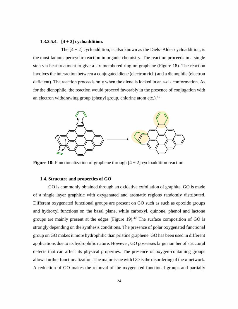
1.3.2.5.4. [4 + 2] cycloaddition.
The [4 + 2] cycloaddition, is also known as the Diels–Alder cycloaddition, is
the most famous pericyclic reaction in organic chemistry. The reaction proceeds in a single
step via heat treatment to give a six-membered ring on graphene (Figure 18). The reaction
involves the interaction between a conjugated diene (electron rich) and a dienophile (electron
deficient). The reaction proceeds only when the diene is locked in an s-cis conformation. As
for the dienophile, the reaction would proceed favorably in the presence of conjugation with
an electron withdrawing group (phenyl group, chlorine atom etc.).41
Figure 18: Functionalization of graphene through [4 + 2] cycloaddition reaction
1.4. Structure and properties of GO
GO is commonly obtained through an oxidative exfoliation of graphite. GO is made
of a single layer graphitic with oxygenated and aromatic regions randomly distributed.
Different oxygenated functional groups are present on GO such as such as epoxide groups
and hydroxyl functions on the basal plane, while carboxyl, quinone, phenol and lactone
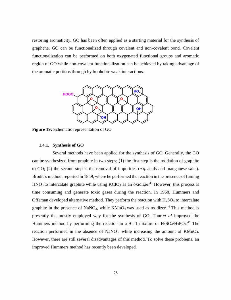
groups are mainly present at the edges (Figure 19).42 The surface composition of GO is
strongly depending on the synthesis conditions. The presence of polar oxygenated functional
group on GO makes it more hydrophilic than pristine graphene. GO has been used in different
applications due to its hydrophilic nature. However, GO possesses large number of structural
defects that can affect its physical properties. The presence of oxygen-containing groups
allows further functionalization. The major issue with GO is the disordering of the π-network.
A reduction of GO makes the removal of the oxygenated functional groups and partially
25
restoring aromaticity. GO has been often applied as a starting material for the synthesis of
graphene. GO can be functionalized through covalent and non-covalent bond. Covalent
functionalization can be performed on both oxygenated functional groups and aromatic
region of GO while non-covalent functionalization can be achieved by taking advantage of
the aromatic portions through hydrophobic weak interactions.
Figure 19: Schematic representation of GO
1.4.1. Synthesis of GO
Several methods have been applied for the synthesis of GO. Generally, the GO
can be synthesized from graphite in two steps; (1) the first step is the oxidation of graphite
to GO; (2) the second step is the removal of impurities (e.g. acids and manganese salts).
Brodie's method, reported in 1859, where he performed the reaction in the presence of fuming
HNO3 to intercalate graphite while using KClO3 as an oxidizer.43 However, this process is
time consuming and generate toxic gases during the reaction. In 1958, Hummers and
Offeman developed alternative method. They perform the reaction with H2SO4 to intercalate
graphite in the presence of NaNO3, while KMnO4 was used as oxidizer.44 This method is
presently the mostly employed way for the synthesis of GO. Tour et al. improved the
Hummers method by performing the reaction in a 9 : 1 mixture of H2SO4/H3PO4.45 The
reaction performed in the absence of NaNO3, while increasing the amount of KMnO4.
However, there are still several disadvantages of this method. To solve these problems, an
improved Hummers method has recently been developed.

26
1.4.2. Covalent functionalization reactions of GO
GO contains different types of oxygenated groups such as hydroxyls, epoxides
and carboxylic acids, these functional group can be functionalized by variety of organic
reaction. The functionalization of GO has to be performed in mild conditions because of the
instability of this material at high temperature.
1.4.2.1. Functionalization of GO through hydroxyl groups
The hydroxyl groups are mainly located on the basal plan of GO. They can
undergo silanization and etherification reactions. The modified Claisen reaction allows to
functionalize the hydroxyl groups of GO through ether bond. Only allylic alcohol of GO
participates in this type of reaction. In this reaction, first the formation of ester, followed by
the rearrangement, and then the formation of a C–C bond with the graphene (Figure 20).46
Figure 20: Functionalization of GO through modified Claisen reaction
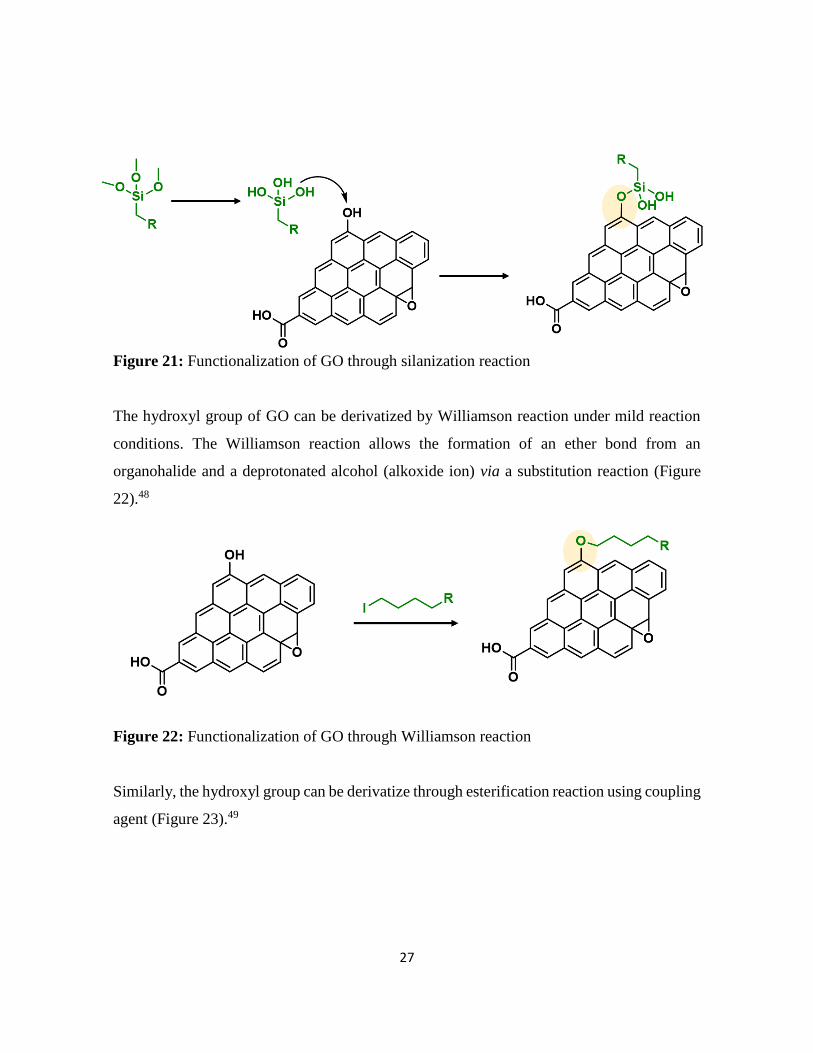
The hydroxyl groups of the GO can be also functionalized through silanization reaction.
Silanization is a two-step reaction. In the first step the hydrolysis of the trialkoxy groups of
the silane and in the second step the reaction between the Si–OH groups and the hydroxyl
groups of GO forming a Si–O–C bond (Figure 21). This reaction has been performed under
mild conditions.47
27
Figure 21: Functionalization of GO through silanization reaction
The hydroxyl group of GO can be derivatized by Williamson reaction under mild reaction
conditions. The Williamson reaction allows the formation of an ether bond from an
organohalide and a deprotonated alcohol (alkoxide ion) via a substitution reaction (Figure
22).48
Figure 22: Functionalization of GO through Williamson reaction
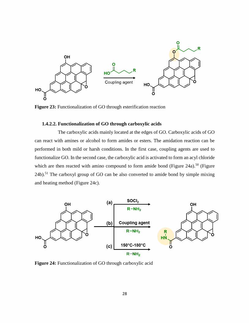
Similarly, the hydroxyl group can be derivatize through esterification reaction using coupling
agent (Figure 23).49
28
Figure 23: Functionalization of GO through esterification reaction
1.4.2.2. Functionalization of GO through carboxylic acids
The carboxylic acids mainly located at the edges of GO. Carboxylic acids of GO
can react with amines or alcohol to form amides or esters. The amidation reaction can be
performed in both mild or harsh conditions. In the first case, coupling agents are used to
functionalize GO. In the second case, the carboxylic acid is activated to form an acyl chloride
which are then reacted with amino compound to form amide bond (Figure 24a).50 (Figure
24b).51 The carboxyl group of GO can be also converted to amide bond by simple mixing
and heating method (Figure 24c).
Figure 24: Functionalization of GO through carboxylic acid

29
1.4.2.3. Functionalization of GO through epoxides
The basal plane of GO mainly contains the epoxy groups. The epoxy goups can be
functionalized through ring-opening reaction. The ring-opening reaction is mainly performed
with amino and thiol compounds (Figure 25).52,53
Figure 25: Functionalization of GO through epoxide group
1.4.3. Non-covalent functionalization reactions of GO
GO can be functionalized through non-covalent bond with small organic
molecules and polymers. The non-covalent functionalization of GO occurs through π–π, H-
bonding, van der Waals, H–π, electrostatic binding, cation–π and anion–π interactions. GO
has been functionalized through non-covalent bond and applied for energy materials,
biosensing, catalytic, and biomedical applications.54
1.5. Synthesis of RGO
The synthesis of graphene is expensive operation, graphene has the tendency to
agglomerates and the mass production is low. Therefore, the researcher focused to developed
new method to obtain cheaper graphene at the industrial scale. The easiest way to obtain
graphene is through the oxidation and exfoliation of graphite to obtain GO, followed by the
reduction. However, RGO is consist of graphene layers but it contains many defect sites in
the basal plane as compared to graphene (Figure 26). A complete reduction of GO to
graphene has not been achieved yet. Different methods have been used to synthesis this
materials from GO such: (i) thermal reduction, (ii) chemical reduction, (iii) microwave
reduction and (iv) electrochemical reduction.55

30
Figure 26: Schematic representation of RGO
1.5.1. Covalent functionalization of RGO
Covalent functionalization of RGO occurs both on oxygenated functional group
and aromatic structure. Although, RGO possess limited amount of oxygenated functional
group. The amount of oxygenated functional groups depends on the reduction method. Thus,
it is important to assess which functions are present and to which extent. RGO is mainly
functionalized on its aromatic domains. All covalent reactions already mentioned for
graphene and GO, can be applied on RGO.
1.5.2. Non-covalent functionalization reactions of RGO
RGO can be functionalized with small organic molecules and polymer through
non-covalent bond such as π–π stacking or van der Waals interactions.
1.6. Characterization
Different characterization techniques have been applied to confirm the structure of
graphene, GO, RGO. In this section Fourier transform infrared (FT-IR) spectroscopy, Raman
spectroscopy, X-ray photoelectron spectroscopy (XPS), thermogravimetric analysis (TGA),
Scanning electron microscopy (SEM), and atomic force microscopy (AFM) will be discussed
in detail.

31
1.6.1. Fourier transform infrared Spectroscopy
The FT-IR spectroscopy is used to identify the functional groups of a molecule.
The FT-IR spectra of graphene showed no significant peak while for GO there are the
characteristic peaks of the oxygenated functional groups. The FT-IR spectrum of GO include
the presence of O–H (3435 cm−1), C O (1735 cm−1), C C (1615 cm−1), and C–O (1052 cm−1)
functional groups (Figure 27). Besides from oxygenated functional group, GO also contains
the adsorbed water, which give strong signal in the spectra. The removal of water content
from GO is difficult because GO is thermally unstable.
Figure 27: FT-IR spectra of GO
1.6.2. Raman spectroscopy
The Raman spectra of graphene and GO represents three main peaks. These peaks
apeared at 1,350 cm–1 ,580 cm–1 and 2,700 cm–1, related to D band, G band and 2D band,
respectively (Figure 28). The G band is due to the sp2 domains of carbon, the D band is due
to the number of defects present in the material, and the 2D band gives information about the
number of layers of the graphene material. In the case of single-layer graphene it is around
24 cm–1, for graphite this band is around 45–60 cm–1. In the case of single-layer graphene it
is around 24 cm–1, for graphite this band is around 45–60 cm–1.

32
Figure 28: Raman spectra of GO
1.6.3. X-Ray photoelectron spectroscopy
XPS giving information on the elemental composition of the samples, chemical
state, the empirical formula and the electronic state of the elements in a sample. The XPS
spectra of graphene shows only one peak in C1s spectral region, at 284.5 eV relating to the
sp2 C=C. In GO we can find many peaks such as sp2 and sp3 carbon atoms, the epoxy,
hydroxyl, carboxylic acid and carbonyl groups at 284.5, 285.2, 287.1, 286.4, 289.2 and 288.0
eV, respectively, in the C1s region (Figure 29).

33
Figure 29: (a) Wide scan XPS spectra of GO, (b) high-resolution C 1s XPS spectra of GO
1.6.4. Thermogravimetric analysis
TGA giving information about the functional groups by calculating the weight
loss as a function of increasing temperature. Graphene is stable at high temperatures.
Functionalized graphene showed weight loss corresponding to the attached functional groups.
The TGA curve of GO shows weight loss between 150 °C and 400 °C that can be assigned
to the thermal decomposition of adsorbed water and oxygenated functional groups (Figure
30). Functionalized GO showed weight loss corresponding to oxygenated functional groups
and the covalently attached molecules.

34
Figure 30: TGA analysis of GO
1.6.5. Scanning electron microscopy
SEM give information about the thickness, size and surface morphology of
graphene and GO. Thicker graphene layers are seen as darker, bilayer graphene shows an
intermediate contrast, whereas monolayer graphene film appeared as a slightly brighter
contrast on silica substrate (Figure 31).
Figure 31: SEM image of GO

35
1.6.6. Atomic force Microscopy
AFM giving information about the surface morphology of GO and graphene at the
nanometer scale. AFM determine the thickness, the number of layers and the lateral size of
GO and graphene. The thickness of GO is 0.9 nm (Figure 32), due to the presence of oxygen
groups, the distance between layers is increased to almost two times more compared to
graphene.
Figure 32: AFM image of GO
1.7. Conclusions
The various graphene synthesis methods are introduced mechanical exfoliation,
ultrasonic cleavage, chemical vapor deposition, epitaxial growth on SiC, and unrolling of
CNTs. GO is usually obtained by the oxidation of graphite. The RGO obtained as a result of
reduction GO. Then the functionalization of graphene, GO and RGO are detailed and
classified between covalent and non-covalent functionalization. Graphene can be
functionalized through covalent bond using free radical addition, nucleophilic addition,
atomic radical addition, electrophilic substitution reactions and cycloaddition. It can be also
functionalized through physical interaction like non-covalent and ionic interaction. GO is

36
mainly covalently functionalized through their oxygenated functions such as carboxylic acids,
hydroxyl groups and epoxides. It can be also functionalized through non-covalent interaction,
ionic interaction and H-bonding. RGO is behave like graphene or GO, depending on the
extent of reduction. However, the main difference between RGO and the graphene is the
presence of defect in the former one. The choice of the materials (graphene, GO and RGO)
depend on the purpose. For example, GO is suitable for biomedical applications, and
graphene is more promising for electronic applications due to their excellent electrical
conductivity. Graphene family member is investigated for only few years, therefore, there is
still a lot to be discovered.

37
1.8. References:
1. G. Rajakumar, X.-H. Zhang, T. Gomathi, S.-F. Wang, M. Azam Ansari, G. Mydhili, G.
Nirmala, M. A. Alzohairy and I.-M. Chung, Processes, 2020, 8, 355.
2. S. Noamani, S. Niroomand, M. Rastgar and M. Sadrzadeh, npj Clean Water, 2019, 2, 1–
14.
3. M. S. Mauter and M. Elimelech, Environ. Sci. Technol., 2008, 42, 5843–5859.
4. C. Hu, Y. Xiao, Y. Zou and L. Dai, Electrochem. Energ. Rev., 2018, 1, 84–112.
5 . U. Kamran, Y.-J. Heo, J. Lee and S.-J. Park, Micromachines, 2019, 10, 234.
6. T. Evans, P. F. James and R. W. Ditchburn, Math. Phys. Sci., 1964, 277, 260–269.
7. M. Gokhale and R. Somani, Mini Rev. Org. Chem., 2015, 12, 355-366.
8. V. Georgakilas, J. A. Perman, J. Tucek, R. zboril, Chem. Rev., 2015, 115, 4744-4822.
9. X. Huang, Z. Yin, S. Wu, X. Qi, Q. He, Q. Zhang, Q. Yan, F. Boey and H. Zhang, Small,
2011, 7, 1876–902.
10. J. Liu, J. Tang and J. Justin Gooding, J. Mater. Chem., 2012, 22, 12435–12452.
11. H. P. Boehm, A. Clauss, G. Fischer, U. Hofmann, Proceedings of the Fifth Conference
on Carbon,, 1962, 1, 73-80.
12. P. Avouris and C. Dimitrakopoulos, Mater. Today, 2012, 15, 86–97.
13. Z. Zhen and H. Zhu, H. Zhu, Z. Xu, D. Xie and Y. Fang, Academic Press, 2018, 1–12.
14. M. Yi and Z. Shen, J. Mater. Chem. A., 2015, 3, 11700–11715.
15. C. Aksoy and D. Anakli, Open Chemi., 2019, 17, 581–586.
16. Y. I. Zhang, L. Zhang, C. Zhou., Acc. Chem. Res., 2013, 46, 2329-2339.
17. D. B. Shinde, J. Debgupta, A. Kushwaha, M. Aslam, V. Pillai, J. Am. Chem. Soc., 2011,
133, 4168-4171.
18. A. C. Kleinschmidt, R. K. Donato, M. Perchacz, H. Beneš, V. Štengl, S. C. Amico and
H. S. Schrekker, RSC Adv., 2014, 4, 43436–43443.
19. D.-M. Chen, P. Shenai and Y. Zhao, Phys. chem. chem. phys., 2011, 13, 1515–20.
20. Z. H. Ni, H. M. Wang, J. Kasim, H. M. Fan, T. Yu, Y. H. Wu, Z. H. Shen., Nano Lett.,
2007, 7, 2758-2763.
21. S. Lee, H. Kim and B. Shim, Carbon Lett., 2012, 62, 1229.

38
22. H. J. Yun and S. Park, New Physics, 2012, 62,1229-1259
23. M. Coroş, F. Pogăcean, L. Măgeruşan, C. Socaci and S. Pruneanu, Front. Mater. Sci.,
2019, 13, 23–32.
24. F. Perreault, A. F. de Faria and M. Elimelech, Chem. Soc. Rev., 2015, 44, 5861–5896.
25. T. Kuila, S. Bose, A. K. Mishra, P. Khanra, N. H. Kim and J. H. Lee, Prog. Mater. Sci.,
2012, 57, 1061–1105.
26. I. A. Vacchi, C. Ménard-Moyon and A. Bianco, Phys. Sci. Rev., 2017, 2.
27. D. Hetemi, V. Noël and J. Pinson, Biosensors, 2020, 10, 4.
28. X. Ma, F. Li, Y. Wang and A. Hu, Chem. Asian J., 2012, 7, 2547–2550.
29. C. K. Chua and M. Pumera, Chem. Soc. Rev., 2013, 42, 3222–3233.
30. X. Xu, P. Li, L. Zhang, X. Liu, H.-L. Zhang, Q. Shi, B. He, W. Zhang, Z. Qu and P.
Liu, Chem. Asian J., 2017, 12, 2583–2590.
31. A. Felten, D. McManus, C. Rice, L. Nittler, J.-J. Pireaux and C. Casiraghi, Appl. Phys.
Lett., 2014, 105, 183104.
32. W. Feng, P. Long, Y. Feng and Y. Li, Adv. Sci., 2016, 3, 1500413.
33. M. H. A. Kudus, M. R. Zakaria, H. Md. Akil, F. Ullah and F. Javed, J. King Saud Univ.
Sci., 2020, 32, 910–913.
34. D. D. Chronopoulos, M. Medveď, G. Potsi, O. Tomanec, M. Scheibe and M. Otyepka,
Chem. Commun., 2020, 56, 1936–1939.
35. C. K. Chua and M. Pumera, Chem. Asian J., 2012, 7, 1009–1012.
36. L. Jin and T. Liu, J. Macromol. Sci. A., 2016, 53, 433–437.
37. S. K. Ujjain, R. Bhatia and P. Ahuja, J. Saudi Chem. Soc., 2019, 23, 655–665.
38. T. A. Strom, E. P. Dillon, C. E. Hamilton and A. R. Barron, Chem. Commun., 2010, 46,
4097–4099.
39. L. Daukiya, C. Mattioli, D. Aubel, S. Hajjar-Garreau, F. Vonau, E. Denys, G. Reiter, J.
Fransson, E. Perrin, M.-L. Bocquet, C. Bena, A. Gourdon and L. Simon, ACS Nano, 2017,
11, 627–634.
40. M. Quintana, K. Spyrou, M. Grzelczak, W. R. Browne, P. Rudolf and M. Prato, ACS
Nano, 2010, 4, 3527–3533.
39
41. J. Li, M. Li, L.-L. Zhou, S.-Y. Lang, H.-Y. Lu, D. Wang, C.-F. Chen and L.-J. Wan, J.
Am. Chem. Soc., 2016, 138, 7448–7451.
42. D. R. Dreyer, S. Park, C. W. Bielawski and R. S. Ruoff, Chem. Soc. Rev., 2010, 39,
228–240.
43. P. Feicht, J. Biskupek, T. E. Gorelik, J. Renner, C. E. Halbig, M. Maranska, F. Puchtler,
U. Kaiser and S. Eigler, Chem. Eur. J., 2019, 25, 8955–8959.
44. H. Yu, B. Zhang, C. Bulin, R. Li and R. Xing, Sci. Rep., 2016, 6, 36143.
45. D. C. Marcano, D. V. Kosynkin, J. M. Berlin, A. Sinitskii, Z. Sun, A. Slesarev, L. B.
Alemany, W. Lu and J. M. Tour, ACS Nano, 2010, 4, 4806–4814.
46. W. Collins, W. Lewandowski, E. Schmois, J. Walish and T. Swager, Angew. Chem. Int.
Ed., 2011, 50, 8848–8852.
47. S. S. Abbas, G. J. Rees, N. L. Kelly, C. E. J. Dancer, J. V. Hanna and T. McNally,
Nanoscale, 2018, 10, 16231–16242.
48. I. A. Vacchi, J. Raya, A. Bianco and C. Ménard-Moyon, 2D Mater., 2018, 5, 035037.
49. I. A. Vacchi, S. Guo, J. Raya, A. Bianco and C. Ménard-Moyon, Chem. Eur. J., 2020,
26, 6591-6598.
50. J. Yao, S. Liu, Y. Huang, S. Ren, Y. Lv, M. Kong and G. Li, Prog. Nat. Sci. Mater.,
2020, 30, 328–336.
51. S. Guo, J. Raya, D. Ji, Y. Nishina, C. Ménard-Moyon and A. Bianco, Nanoscale Adv.,
2020, 2, 4085–4092.
52. H. Thomas, A. Marsden, M. Walker, N. Wilson and J. Rourke, Angew. Chem. Int. Ed.,
2014, 53, 7613-7618.
53. I. A. Vacchi, C. Spinato, J. Raya, A. Bianco and C. Ménard-Moyon, Nanoscale, 2016,
8, 13714–13721.
54. V. Georgakilas, J. N. Tiwari, K. C. Kemp, J. A. Perman, A. B. Bourlinos, K. S. Kim
and R. Zboril, Chem. Rev., 2016, 116, 5464–5519.
55. J. Feng, Y. Ye, M. Xiao, G. Wu and Y. Ke, Chem. Pap., 2020, 74, 3767–3783.

40
Chapter 2
Covalent functionalization of graphene with redox-active
organic molecules for energy storage

41
2. Introduction ……………………………………………………………………. 42
2.1. Redox-active organic molecules and their operating mechanism 44
2.2. Scope of the research …………………………………………………………… 46
2.3. Covalent functionalization of graphene with redox-active organic
molecules for SCs ……………………………………………………………... 48
2.3.1. Small redox-active molecules-functionalized graphene for SCs ………….. 48
2.3.2. Conductive polymer functionalized graphene for SCs ……………………. 51
2.4. Covalent functionalization of graphene with redox-active organic
molecules for LIBs ……………………………………………………………. 54
2.4.1. Small redox-active molecules-functionalized graphene for LIBs ………… 54
2.4.2. Conductive polymer functionalized graphene for LIBs …………………… 56
2.5. Conclusion and challenges ……………………………………………………. 57
2.6. References …………………………………………………………………….. 59

42
2. Introduction
Graphene-based materials have attracted considerable interest in electrochemical
applications due to their abundance, processability, stability, and relatively environmentally
friendly characteristics.1 Graphene has been widely used as electrode materials. Some of the
useful properties of GO and graphene-based electrodes include electrochemical stabilities
and wide potential windows for repetitive redox reactions.2 The sp2 and/or sp3 hybridized
carbons and some of the oxygenated functional groups provide reactive sites for surface
functionalization, which is beneficial to electrochemical applications, especially for electrode
materials.
The covalent functionalization could significantly change the electrical structure and
properties of the graphene.3,4 In particular, acid (e.g., nitric acid or sulfuric acid)-promoted
oxidation is one of the most commonly used methods for covalent functionalization.5,6 The
carbon atoms in graphene can form robust covalent bonds with organic molecules, giving
rise to a variety of composites with distinguished properties. The surface functionalized
graphene and GO have been used for a number of applications such as catalysis,7,8 energy
conversion,9,10 sensing,11,12 separation media,13–17 and biomedicine.18–20 However, most of
the applications rely on the concept of electrochemistry.21,22
The fundamental components in electrochemical processes are the electrodes. graphene
shows high chemical stability,23 good mechanical properties,24,25 and high electrical
conductivity.26,27 However, despite the potentials of graphene-based material, a common
problem is the low surface wettability,28 which lead to a low utilization rate of specific
surface area, and result in low energy storage. Change of the surface chemistry by
functionalization is a common route to optimize the interaction of the graphene surface with
the external environment. The modification of the surface chemistry of graphene strongly
improves their interaction with aqueous and organic environments, providing improve
performance as electrode materials in energy storage systems.
Covalent modification with organic molecules is expected to allow fine control of the
function and physical properties at atomic or molecular levels. The covalent functionalization

43
of graphene with redox-active materials (organic molecules and conductive polymer) have
been performed by nitrene and diazonium chemistry for sp2 carbons, ring-opening reaction
of epoxide group, etherification reaction, esterification reaction, amidation reaction and
cyclization reaction (Figure 1). The detail explanation of each functionalization method is
already discussed in section 1.
Figure 1: Various functionalization routes of graphene with redox-active molecules (a)
toward sp2 carbons framework of graphene and (b) toward oxygenated functional groups on
GO. (c) Preparation strategies of graphene-polymer composites
44
2.1. Redox-active organic molecules and their operating mechanism
According to the growth of renewable energy utilization, demands for advanced
energy storage devices with high efficiency are increasing. To solve the problems of global
energy consumption, the development of high-performance and low-cost clean energy
devices is required. LIBs and SCs are two of the most promising energy storage devices due
to their notable characteristics, such as high energy density,29 high power density,30 and long
cycle life.31 For instance, widespread success has been achieved for LIBs since their
commercialization in the 1990s.32 Current commercial LIBs are constructed with metal-
based materials, such as LiMn2O4,33
LiCoO2,34 and LiFePO4,
35 on the cathode side and
carbon-based materials such as graphite on the anode side. In the case of SCs,
pseudocapacitive materials, such as metal oxides, sulfides, selenides and phosphides, are
widely explored to enhance energy density.36 However, the concerns of high cost, limited
availability, and electronic hazards of transition metals, as well as poor cycling stability,
would hinder their practical use.37 Thus, metal-free redox-active organic materials for the
fabrication of electrodes have been widely studied and can be potential candidates for the
next-generation energy storage.
The first organic electrode was introduced by Williams using dichloroisocyanuric acid as an
active material for a primary battery in 1969.38 After this study, a variety of redox-active
organic molecules have been studied, including small organic molecules such as quinones,
dianhydrides and conjugated polymers such as polypyrrole and polyacetylene. The reported
redox-active organic molecules can be categorized into carbonyl compounds,39 organic
radicals,40 organosulfur compounds,41 phenazine derivatives,42 and conductive polymers
(Figure 2).43

45
Figure 2: Classification of organic redox-active molecules
Redox-active organic molecules have attracted more and more interest recently, due to their
intrinsic and reliable redox behavior, which can be readily utilized for charge‐storage
memory applications. A redox-active molecule contains a redox component acting as the
charge‐storage center surrounded by insulators/barriers. The electrons tunnel through the
barrier during the oxidation and reduction processes. Typically, the application of an
oxidation voltage will cause electron loss in the redox molecules; reversely, the electrons will
be driven back to the molecules by applying a reduction voltage. Generally, the redox
molecules have multiple stable states. The switching between these states is dynamically
reversible through the loss or capture of a charge, that is, oxidation and reduction of the redox
centers (Figure 3).

46
Figure 3: Redox mechanisms of various types of organic redox-active molecules
Up to now, several reviews were published on the organic electrode for energy devices;
Schon,44 Shanmukaraj,45 Shea,46 Han,47 and Song,48 independently reported the progress of
the organic-based electrode for SCs and LIBs, all of which have mentioned difficulties in the
development of organic electrodes. First, the organic molecules on electrodes tend to dissolve
into the electrolytes, which results in a poor cycle life.49 Second, their poor conductivity,
resulting in limited electrochemical performance; as a result, their potential cannot be
withdrawn completely due to the insulative effect.50 Covalent functionalization strategy is
expected to solve these problems.
2.2. Scope of the research
The organic modification of nanocarbons can be classified into covalent,51 non-
covalent,52 and ionic bond53 formations. Organic molecules have been functionalized on
nanocarbon through non-covalent interactions and ionic bonding; as a result, high capacity,
energy density, and power density were obtained.54 Li,55 Yuan,56 Notarianni,57 and Iqbal58
independently reviewed the progress of the carbon-based composites as electrode materials
for SCs and LIBs (Figure 4), focusing mainly on physical (non-covalent) interactions.
However, since physical interactions are weak, molecular dissociation occurs readily.59,60

47
Also, the rapid fading of electrode performance due to the volume change during charge–
discharge cycles is a problem that needs to be addressed. The covalent functionalization of
graphene results in the formation of durable materials.61 The electrochemical performance of
redox-active organic molecules can be properly regulated by introducing redox-active
molecules via diverse organic reactions. Covalent binding of redox-active organic molecules
with graphene improves the transfer rate of electron and prevents the dissolution of the redox-
active material, resulting in good conductivity and long cycle life.62,63 In this literature review,
I will summarize and discuss the reported literature based on the covalent modification of
redox-active organic molecules on graphene and their electrochemical stability as electrode
material in SCs and LIBs.
Figure 4: Schematic representation of the working principle of (a) SCs and (b) LIBs
48
2.3. Covalent functionalization of graphene with redox-active organic molecules
for SCs
2.3.1. Small redox-active molecules-functionalized graphene for SCs
SCs are attractive for high power applications because of their ability to rapidly
store/release electrical energies.64–66 High-performance SCs should have large specific
capacitances, high-power capabilities, and ultra-long cycle lives. Among the proposed
applications of graphene-based materials, SCs, also known as electrochemical capacitors,
have attracted much attention for the past decade. Compared with secondary batteries,
graphene-based SCs are electrochemical energy storage devices that promise outstanding
power density, charge/discharge rate, cycling stability, and operational safety.67 SCs are
often utilized individually or in tandem with batteries for energy storage and supply. Based
on their energy storage mechanisms, SCs are mainly classified into electrical double-layer
capacitors (EDLCs) and pseudocapacitor.68,69 EDLCs store energy by electrostatic charge
accumulation at electrode/electrolyte interfaces, while the pseudocapacitance is mainly
attributed to the redox reactions at electrode surfaces (Figure 4a).
The covalent attachment of redox-active molecules to graphene has been proven to be a
viable means of increasing electron transfer rates and preventing the dissolution of redox-
active material, leading to a good cycle life.70 When redox-active molecules are covalently
attached on graphene, they can represent reversible reactions; therefore, electrodes can have
both pseudocapacitance and EDLC mechanism simultaneously. Thus, the energy density of
the electrode enhances and results in a stable behavior without any structural disturbance.
Selected examples are summarized in Table 1. RGO was functionalized with
phenylenediamine (RGO-PD),71 2-aminoanthraquinone (RGO-AAQ),72 and 2-aminopyrene-
3,4,9,10-tetraone (RGO-PYT)73 through nucleophilic ring-opening reaction of epoxide group
and applied for SCs. The resulting composite materials showed a capacitance retention of
92%, 100%, and 100%, respectively. The covalently bonded redox-active moieties contribute
to the pseudocapacitance. Graphene provides a large specific surface area for forming electric
double layers, works as a host material for the redox-active molecules, and promotes charge
transfer and electrolyte diffusion. Edges of graphene can be functionalized by cyclization

49
reaction at carboxylic groups.74,75 The prepared composite material displays a capacitance
retention of 98% after 9000 cycles. The cyclization reaction does not destroy the in-plane sp2
framework of graphene, allowing better electrical conductivity. However, this
functionalization method requires phosphoric acid catalyst and multistep reactions. Thiourea
functionalized GO (RGO-TU) was prepared through amide bond.76 The specific capacitance
of the material increases slightly in the initial cycles and then become stable with no obvious
loss in specific capacitance after long cycling. We assume that the sulfur-containing thiourea
is activated in the first few cycles and undergoes redox reaction. In another report, adenine
(AD) was functionalized on GO (GO-AD) through amide bond.77 The GO-AD electrode
exhibited excellent cycling retention of 100% after 1000 cycles. But, the reaction was
performed at room temperature; therefore, the functionalization might occur only at the
epoxide groups instead of carboxyl groups. Another approach for graphene functionalization
is diazonium chemistry. Anthraquinone (AQ) molecules were grafted on graphene through
diazonium chemistry, forming covalently linked graphene framework (G-AQ). Covalently
linked AQ molecules worked as pillars to construct graphene framework and prevented the
restacking of graphene sheets during fabrication processes. The capacitance retention of G-
AQ was 96% after 5000 cycles.78 Similarly, 2-amino-3-chloro-1,4-naphthoquinone (ACNQ)
molecules were introduced onto graphene via diazonium chemistry (G-CNQ).79 The
electrode exhibited a long cycling life, nearly no loss after 10,000 cycles. Diazonium
chemistry is simple, fast, and efficient. The key species of the reaction is an aryl radical,
which readily adds to carbon frameworks at the basal planes and edges, achieving a sufficient
introduction of functional groups. To summarize this section, the order of the desirable
functionalization is diazonium chemistry > cyclization > amidation reaction > reaction
through epoxide group (Figure 5), although the investigation may not be comprehensively
performed.

50
Figure 5: Comparison of different covalent functionalization methods toward
electrochemical stability
Table 1: Small redox-active molecules-functionalized graphene for SCs
Material Functionalization reaction Cycle
number
Capacity
retention Ref.
RGO-PD Ring opening of epoxide 1000 92% [71]
RGO-AAQ Ring opening of epoxide 1000 100% [72]
RGO-PYT Ring opening of epoxide 25000 100% [73]
G-BBO Cyclization (phosphoric acid-
catalyzed cyclization reaction) 9000 98% [74]
G-BO Cyclization (phosphoric acid-
catalyzed cyclization reaction) 2000 100% [75]
RGO-TU Amidation and ring opening of
epoxide 10000 100% [76]
GO-AD Amidation (mixing and heating) 1000 100% [77]
G-AQ Diazonium chemistry 5000 96% [78]
G-CNQ Diazonium chemistry 10000 100% [79]

51
2.3.2. Conductive polymer functionalized graphene for SCs
Polymer‐based SCs offer some unique properties such as controllable solubility,
precise optimization of potential, variety of counter ions, flexible or even bendable electrodes
and, subsequently, devices can be fabricated.80 Various graphene–polymer composites with
non-covalent and covalent interaction have been synthesized, and high capacitive
performances have been achieved. The non-covalent interaction between graphene and
polymers limits charge transfer at their interface and causes volumetric change during the
charge-discharge cycles, reducing the cycling stability when applied for electrode
materials.81–84 To overcome this issue, polymers were introduced on graphene through
covalent bond. At the same time, the polymer structure plays important roles, both in stability
and capacitance. Various types of polymers have been introduced on graphene through
covalent bond and applied for SCs (Table 2). PANI was functionalized on RGO (RGO-
PANI) through introduction of carboxyl group on RGO, amidation, followed by oxidative
polymerization. Diazonium chemistry is widely employed for the covalent functionalization
of RGO, because it can prevent the graphene sheets from aggregating during the
functionalization. In addition, RGO can provide an excellent conducting path to the grafted
PANI and improve the charge transport of PANI. The cycling stability of nanocomposite
after 1000 cycles was 72% of the initial capacitance.85 Similarly, poly(3,4-
ethylenedioxythiophene) was covalently grafted onto RGO, which was prefunctionalized
with thiophene by diazonium chemistry (RGO-PEDOT). Thiophene was used as linker,
followed by chemical polymerization. Thiophene unit on GO promotes the selective
polymerization with EDOT at the 2- and 5-positions of thiophene, forming covalently grafted
GO-PEDOT. The prepared material showed a capacitance retention of 80% after 1000
cycles.86 Also, PANI was introduced on RGO using PD as an linker. The capacitance
retention in a range of 82%-90% was obtained.87–89 These results suggest that the type of
linker affect the electrochemical stability. Using cyclization reaction, 1,3-bis(2-
benzimidazolyl)-5-aminobenzene was functionalized on RGO (RGO-BOA). The
capacitance retention of electrode materials was 88% after 5000 cycles.90 Through amide
linkage, melamine was functionalized on RGO (RGO-M), and then nanocomposite with

52
polyorthoaminophenol was prepared (RGO-M-PAP). The prepared material was applied as
an electrode, with a capacity retention of 90% after 1000 cycles.91 This result suggests that
nitrogen-containing RGO has the potential to improve the electrochemical behavior of SCs.
In another work, PPD was functionalized on RGO (RGO–PPD) through amide bond, using
thionyl chloride activation method, followed by polymerization. The composite exhibits
excellent cycling stability, maintaining 90% of its initial capacitance after 1000 cycles.92 The
excellent SCs properties rely on the polymer nanoparticles wrapped within or on the graphene
surface, providing a large surface area and high pore volume of RGO. To further improve
the electrochemical performance, organic dopant was introduced into the structure of PANI
which is covalently functionalized on the surface of graphene (G-PANI) through diazonium
chemistry. The resulting material showed high electrochemical stability in cycling, with 95%
of capacitance retention after 1000 cycles.93 The synthesized composites showed a unique
hierarchical morphology, which increased the accessible surface area for the redox reaction
and allowed faster ion diffusion for excellent electrochemical performance. Recently, we
reported graphene–polymer composite through ring opening reaction of epoxides (RGO-
SBP). The composite was synthesized using a three-step reaction involving a cross-linker,
initiator, and monomer. The prepared material demonstrated a cycling stability of 98% after
1000 cycles.94 Furthermore, RGO was functionalized with a redox-active thiourea-
formaldehyde polymer (TF), yielding a multifunctional hybrid system (RGO-TF). The
functionalization of the RGO was performed by thiol-carboxylic-acid esterification. The
presence of multiple functional groups comprising sulfur, nitrogen, and oxygen provide
additional contribution of faradaic redox reaction in SCs, leading to effective
pseudocapacitances. The prepared material exhibited good cycling stability with a
capacitance retention of 100% after 5000 cycles.95 The literature reveals that the most
important point for the electrochemical stability is the structure of polymer along with
covalent connection. The introduction of proper linker, and construction of multifunctional
polymer increase the stability as well as the specific capacitance of polymer-graphene
composites.

53
Table 2: Conductive polymer functionalized graphene for SCs
Materials Functionalization reaction Cycle
number
Capacity
retention Ref.
RGO-PANI Diazonium chemistry 1000 72% [85]
RGO-PEDOT Diazonium chemistry 1000 80% [86]
RGO-PANI Diazonium chemistry 2000 83% [87]
RGO-PANI Ring opening of epoxide 10000 82% [88]
RGO-PANI Ring opening of epoxide 1000 81% [89]
RGO-BOA Cyclization 5000 88% [90]
RGO-M-PAP Amidation 1000 90% [91]
RGO-PPD Amidation (SOCl2
activation) 1000 90% [92]
G-PANI Diazonium chemistry 1000 95% [93]
RGO-SBP Ring opening of epoxide 1000 98% [94]
RGO-TF Esterification 5000 100% [95]

54
2.4. Covalent functionalization of graphene with redox-active organic molecules for
LIBs
2.4.1. Small redox-active molecules-functionalized graphene for LIBs
Small organic molecules covalent grafted onto the surface of graphene can result
in a high capacity and maintain excellent cycling stability in LIBs. To date, several
approaches for covalent functionalization of graphene have been reported (Table 3). AQ was
grafted on RGO (RGO-AQ) through nitrene chemistry. The material showed a capacity
retention of 70% after ten cycles in LIBs.96 The cycling stability of the material decreases
significantly, indicating the formation of RGO-AQ via nitrene is not ideal. To further improve
the electrochemical stability, graphene was functionalized with an organic radical, 4-
hydroxy-2,2,6,6-tetramethylpiperidin-1-oxyl (4-hydroxy-TEMPO), through esterification
reaction. This composite has an electrically conductive network of graphene sheets with
abundant electrochemically active nitroxide radical functionalities. However, when the
prepared material was applied as an electrode, the capacity decreases in the first few cycles,
suggesting the instability of the ester bond.97 Esterification was also investigated for the
functionalization of tetrahydroxybenzoquinone (THBQ) on GO (GO-THBQ). GO-THBQ
was applied as electrode for LIBs and demonstrated a cycling stability of 68% after 2000
cycles.98 Similarly, carboxyl-enriched RGO was functionalized with nitroxide radical (RGO-
NO) via one-step esterification. The capacity retention of RGO-NO was 89% after 2000
cycles, derived from the folded RGO-NO structure that shortens the distance of electron
transport between radicals.99 These results suggest that ester bonding is not stable. In another
report, N,N′-diamino-1,4,5,8-naphthalenetetracarboxylic bisimide (DNTCB)-functionalized
GO (GO-DNTCB) was prepared by amidation. The resulting material showed a capacity
retention of 85% after 50 cycles in LIBs electrode.100 Similarly, GO was functionalized with
naphthalenediimide diamine (NDIDA) through amide bond (GO-NDIDA), using
conjugating linker. GO-NDIDA exhibits a capacity retention of 100% after 50 cycles with
the aid of conjugated linker (aniline).101 These results suggested that the introduction of a
conjugated linker between graphene and redox-active molecules can improve the
electrochemical stability. The functionalization of graphene through the amide bond is the

55
better approach to achieve stability under electrochemical reactions. This is because amide
is the most stable form in carboxyl acid derivatives.
To summarize this section, the order of the desirable functionalization is amidation >
esterification > nitrene chemistry (Figure 6), although there is still room for consideration.
Figure 6: Comparison of different covalent functionalization methods of graphene toward
electrochemical stability
Table 3: Small redox-active molecules-functionalized graphene for LIBs
Material Functionalization reaction Cycle
number
Capacity
retention Ref
RGO-AQ Cyclization (nitrene chemistry) 10 70% [96]
GO-TEMPO Esterification (SOCl2 activation) 400 65% [97]
GO-THBQ Esterification (simple mixing) 2000 68% [98]
RGO-NO Esterification (SOCl2 activation) 200 89% [99]
GO-DNTCB Amidation (coupling reagent) 50 85% [100]
GO-NDIDA Amidation (coupling reagent) and
conductive linker 50 100% [101]

56
2.4.2. Conductive polymer functionalized graphene for LIBs
Surface covalent functionalization of graphene sheets by polymers has been
verified as an effective approach to keep the sheets from restacking in the composite
materials, which is a different solution to allow utilization of the surface groups of graphene
sheets (Table 4).102,103 Covalently grafted graphene with polysulfur (G-PS) was synthesized
through inverse vulcanization, and applied for ultra-high loading Li−polyS batteries.104 The
prepared material showed a capacity retention of 67% after 100 cycles. Graphene sheets
improve the conductivity and stability of polysulfides matrix. The nitroxide radical polymer,
poly(2,2,6,6-tetramethylpiperidinyloxy-4-ylmethacrylate) (PTMA), gains attention as a
promising cathode material for high-rate, organic radical batteries, which is also called as
organic radical polymer battery.105 Graphene covalently functionalized with radical polymer
(G-PTMA), via surface-initiated atom transfer radical polymerization, and applied for LIBs.
After 250 cycles, the capacity retention of the prepared material was almost 70%. The
covalently bonded PTMA could interact with graphene sheets at a molecular level, improving
electron and ion transportation. G-PTMA could also inhibit the restacking of graphene sheets
during the electrode fabrication process.106 However, this method requires several
preparation steps, which is time-consuming and requires metallic catalyst.
To summarize this section, atom transfer radical polymerization reaction showed relatively
good electrochemical stability than synthesis and grafting of polymer through inverse
vulcanization.
Table 4: Conductive polymer functionalized graphene for LIBs
Materials Functionalization reaction Cycle
number
Capacity
retention Ref.
G-PS Ring opening of epoxide and
Inverse vulcanization 100 67% [104]
G-PTMA
Diazonium chemistry and
atom transfer radical
polymerization
250 70% [106]

57
2.5. Conclusion and challenges
Here, I summarized the covalent functionalization of graphene with redox-active
small molecules and polymers and compared their performances for SCs and LIBs. Covalent
binding of redox-active organic molecules to graphene has been demonstrated to be a
promising strategy. The covalently bonded composites prevent the dissolution of small
redox-active molecules, stabilize the polymer structure, and shows better electrochemical
stability than non-covalently bonded ones. However, the current covalent functionalization
methods required harsh reaction conditions, complicated procedures and accompanied with
biproduct formation (Table 5). Therefore, the improvement of the current functionalization
method is needed to achieve cost effective, eco-friendly and high-performance electrode
materials. Also, the literature survey reveals that comprehensive research has not been done
on the covalent functionalization of graphene for energy storage applications, despite the
development of various types of organic transformations in recent years. Therefore, further
investigation is needed for developing advanced electrode materials.

58
Table 5: Characteristics and issues of each covalent functionalization method
Methods for
functionalization of
graphene
Characteristics Issues
Diazonium chemistry Simple, stable, basal-plane
functionalization
Disrupt the sp2 framework,
side reactions can occur
Amidation
Preserve the sp2 framework,
well-established chemistry,
stable
Functionalization only at the edge,
harsh reaction condition, hydrolysis
can occur
Ring opening of epoxide
Simple, mild condition,
basal-plane
functionalization
Disrupt the sp2 framework,
less stable
Cyclization Stable, preserve the sp2
framework
Harsh reaction conditions
(phosphoric acid), multistep
reaction
Esterification Preserve the sp2 framework,
strong
Harsh reaction condition (SOCl2
activation), less stable (hydrolysis),
functionalization only at the edge
Nitrene chemistry Simple, basal-plane
functionalization
Harsh reaction conditions (180 °C),
less stable
Etherification Stable, basal-plane
functionalization
Harsh reaction condition,
disrupt the sp2 framework

59
2.6. References
1. A. Borenstein, O. Hanna, R. Attias, S. Luski, T. Brousse and D. Aurbach, J. Mater.
Chem. A, 2017, 5, 12653–12672.
2. P. R. Unwin, A. G. Güell and G. Zhang, Acc. Chem. Res., 2016, 49, 2041–2048.
3. A. Kasprzak, K. Fateyeva, M. Bystrzejewski, W. Kaszuwara, M. Fronczak, M. K.
Stawinska and M. Poplawska, Dalton Trans., 2018, 47, 11190–11202.
4. T. J. M. Fraga, M. N. Carvalho, M. G. Ghislandi, M. A. D. M. Sobrinho, T. J. M. Fraga,
M. N. Carvalho, M. G. Ghislandi and M. A. D. M. Sobrinho, Brazilian J. Chem. Eng.,
2019, 36, 1–31.
5. M. N. Tchoul, W. T. Ford, G. Lolli, D. E. Resasco and S. Arepalli, Chem. Mater., 2007,
19, 5765–5772.
6. C. Li, X. Chen, L. Shen and N. Bao, ACS Omega, 2020, 5, 3397–3404.
7. E. Lam and J. H. T. Luong, ACS Catal., 2014, 4, 3393–3410.
8. M. J. Lázaro, S. Ascaso, S. Pérez-Rodríguez, J. C. Calderón, M. E. Gálvez, M. J. Nieto,
R. Moliner, A. Boyano, D. Sebastián, C. Alegre, L. Calvillo and V. Celorrio, C. R.
Chim., 2015, 18, 1229–1241.
9. W. J. Liu, H. Jiang and H. Q. Yu, Energy Environ. Sci., 2019, 12, 1751–1779.
10. C. Hu, Y. Xiao, Y. Zou and L. Dai, Electrochem. Energ. Rev., 2018, 1, 84–112.
11. M. D. Angione, R. Pilolli, S. Cotrone, M. Magliulo, A. Mallardi, G. Palazzo, L.
Sabbatini, D. Fine, A. Dodabalapur, N. Cioffi and L. Torsi, Mater. Today, 2011, 14,
424–433.
12. M. Pan, Z. Yin, K. Liu, X. Du, H. Liu and S. Wang, Nanomaterials, 2019, 9, 1330.
DOI:10.3390/nano9091330.
13. E. Kanao, T. Kubo and K. Otsuka, Bull. Chem. Soc., 2020, 93, 482–489.
14. X. Yang, Y. Wan, Y. Zheng, F. He, Z. Yu, J. Huang, H. Wang, Y. S. Ok, Y. Jiang and
B. Gao, Chem. Eng. J., 2019, 366, 608–621.
15. A. Azari, R. Nabizadeh, S. Nasseri, A. H. Mahvi and A. R. Mesdaghinia, Chemosphere,
2020, 250, 126238.
16. R. Gusain, N. Kumar and S. S. Ray, Coord. Chem. Rev., 2020, 405, 213111.
60
17. M. Selvaraj, A. Hai, F. Banat and M. A. Haija, J. Water Process Eng., 2020, 33,
100996.
18. C. Cha, S. R. Shin, N. Annabi, M. R. Dokmeci and A. Khademhosseini, ACS Nano,
2013, 7, 2891–2897.
19. A. M. Monaco and M. Giugliano, Beilstein J. Nanotechnol., 2014, 5, 1849–1863.
20. L. S. Porto, D. N. Silva, A. E. F. de Oliveira, A. C. Pereira and K. B. Borges, Rev. in
Anal. Chem, 2019, 38. DOI:10.1515/revac-2019-0017.
21. Y. E. Jeun, B. Baek, M. W. Lee and H. S. Ahn, Chem. Commun., 2018, 54, 10052–
10055.
22. M. Starowicz, B. Stypuła and J. Banaś, Electrochem. Commun., 2006, 8, 227–230.
23. L. Fagiolari and F. Bella, Energy Environ. Sci., 2019, 12, 3437–3472.
24. X. Zhang, L. Ge, Y. Zhang and J. Wang, Materials, 2019, 12.
DOI:10.3390/ma12223759.
25. A. Takakura, K. Beppu, T. Nishihara, A. Fukui, T. Kozeki, T. Namazu, Y. Miyauchi
and K. Itami, Nat. Commun., 2019, 10, 3040.
26. I. M. Alarifi, J. Mater. Res. Technol., 2019, 8, 4863–4893.
27. S. Zhang, W. Xiao, Y. Zhang, K. Liu, X. Zhang, J. Zhao, Z. Wang, P. Zhang and G.
Shao, J. Mater. Chem. A, 2018, 6, 22555–22565.
28. J. Feng and Z. Guo, Nanoscale Horiz., 2019, 4, 339–364.
29. Y. Qiao, K. Jiang, H. Deng and H. Zhou, Nat. Catal., 2019, 2, 1035–1044.
30. C. Choi, D. S. Ashby, D. M. Butts, R. H. DeBlock, Q. Wei, J. Lau and B. Dunn, Nat.
Rev. Mater., 2020, 5, 5–19.
31. Y. Zhao, C. Wu, J. Li and L. Guan, J. Mater. Chem. A, 2013, 1, 3856–3859.
32. J. B. Goodenough, Nat. Electron., 2018, 1, 204–204.
33. J. Drews, R. Wolf, G. Fehrmann and R. Staub, J. Power Sources, 1997, 65, 129–132.
34. J. Qian, L. Liu, J. Yang, S. Li, X. Wang, H. L. Zhuang and Y. Lu, Nat. Commun., 2018,
9, 4918.
35. C. T. Hsieh, C. T. Pai, Y. F. Chen, P. Y. Yu and R. S. Juang, Electrochim. Acta, 2014,
115, 96–102.

61
36. J. H. Kim, S. Lee, J. Choi, T. Song and U. Paik, J. Mater. Chem. A, 2015, 3, 20459–
20464.
37. M. E. Bhosale, S. Chae, J. Man Kim and J. Y. Choi, J. Mater. Chem. A., 2018, 6,
19885–19911.
38. D. L. Williams, J. J. Byrne and J. S. Driscoll, J. Electrochem. Soc., 1969, 116.
39. L. I. U. Mengyun, G. U. Tiantian, Z. Min, W. Kangli, C. Shijie and J. Kai, Energy
Storage Sci. Technol., 2018, 7, 1171.
40. C. Friebe and U. S. Schubert, Top. Curr. Chem., 2017, 375, 19–19.
41. B. Boateng, Y. Han, C. Zhen, G. Zeng, N. Chen, D. Chen, C. Feng, J. Han, J. Xiong, X.
Duan and W. He, Nano Lett., 2020, 20, 2594–2601.
42. M. Lee, J. Hong, B. Lee, K. Ku, S. Lee, C. B. Park and K. Kang, Green Chem., 2017,
19, 2980–2985.
43. H. Wang, J. Lin and Z. X. Shen, Adv. Mater. Dev., 2016, 1, 225–255.
44. T. B. Schon, B. T. McAllister, P. F. Li and D. S. Seferos, Chem. Soc. Rev., 2016, 45,
6345–6404.
45. D. Shanmukaraj, P. Ranque, H. B. Youcef, T. Rojo, P. Poizot, S. Grugeon, S. Laruelle
and D. Guyomard, J. Electrochem. Soc., 2020, 167, 070530.
46. J. J. Shea and C. Luo, ACS Appl. Mater. Interfaces, 2020, 12, 5361–5380.
47. C. Han, H. Li, R. Shi, T. Zhang, J. Tong, J. Li and B. Li, J. Mater. Chem. A, 2019, 7,
23378–23415.
48. Z. Song and H. Zhou, Energy Environ. Sci., 2013, 6, 2280–2301.
49. Y. Lu, Q. Zhang, L. Li, Z. Niu and J. Chen, Chem, 2018, 4, 2786–2813.
50. Y. Lu and J. Chen, Nat. Rev. Chem., 2020, 4, 127–142.
51. V. Georgakilas, M. Otyepka, A. B. Bourlinos, V. Chandra, N. Kim, K. C. Kemp, P.
Hobza, R. Zboril and K. S. Kim, Chem. Rev., 2012, 112, 6156–6214.
52. D. Tuncel, Nanoscale, 2011, 3, 3545–3554.
53. Z. Liu, T. Rios-Carvajal, M. P. Andersson, M. Ceccato, S. L. S. Stipp and T.
Hassenkam, Environ. Sci. Nano, 2019, 6, 2281–2291.
54. F. Tournus, S. Latil, M. I. Heggie and J. C. Charlier, Phys. Rev. B, 2005, 72, 075431.

62
55. Q. Li, M. Horn, Y. Wang, J. MacLeod, N. Motta and J. Liu, Materials, 2019, 12, 703.
56. W. Yuan, Y. Zhang, L. Cheng, H. Wu, L. Zheng and D. Zhao, J. Mater. Chem. A, 2016,
4, 8932–8951.
57. M. Notarianni, J. Liu, K. Vernon and N. Motta, Beilstein J. Nanotechnol., 2016, 7, 149–
196.
58. S. Iqbal, H. Khatoon, A. H. Pandit and S. Ahmad, Mater. Sci. Energy Technol., 2019, 2,
417–428.
59. C. A. Dyke and J. M. Tour, J. Phys. Chem. A, 2004, 108, 11151–11159.
60. G. Speranza, J. Carbon Res., 2019, 5, 84.
61. I. A. Vacchi, C. Ménard-Moyon and A. Bianco, Phys. Sci. Rev., 2017, 2, 035037.
DOI:10.1515/psr-2016-0103.
62. A. Bakandritsos, P. Jakubec, M. Pykal and M. Otyepka, FlatChem., 2019, 13, 25–33.
63. A. Jaffe, A. S. Valdes and H. I. Karunadasa, Chem. Mater., 2015, 27, 3568–3571.
64. N. A. Elessawy, J. E. Nady, W. Wazeer and A. B. Kashyout, Sci. Rep., 2019, 9, 1129.
65. R. Vellacheri, A. Al-Haddad, H. Zhao, W. Wang, C. Wang and Y. Lei, Nano Energy,
2014, 8, 231–237.
66. F. Zhang, T. Zhang, X. Yang, L. Zhang, K. Leng, Y. Huang and Y. Chen, Energy
Environ. Sci., 2013, 6, 1623–1632.
67. L. L. Zhang, R. Zhou and X. S. Zhao, J. Mater. Chem., 2010, 20, 5983–5992.
68. H. Ji, X. Zhao, Z. Qiao, J. Jung, Y. Zhu, Y. Lu, L. L. Zhang, A. H. MacDonald and R.
S. Ruoff, Nat. Commun., 2014, 5, 3317.
69. Y. M. Volfkovich, A. A. Mikhailin, D. A. Bograchev, V. E. Sosenkin and V. S.
Bagotsky, Recent Trend Electrochem. Sci. Technol., 2012, 159.
70. S. Seo, M. Min, S. M. Lee and H. Lee, Nat. Commun., 2013, 4, 1920.
71. M. M. Sk and C. Y. Yue, RSC Adv., 2014, 4, 19908–19915.
72. Q. Wu, Y. Sun, H. Bai and G. Shi, Phys. Chem. Chem. Phys., 2011, 13, 11193–11198.
73. J. Shi, Z. Zhao, J. Wu, Y. Yu, Z. Peng, B. Li, Y. Liu, H. Kang and Z. Liu, ACS Sustain.
Chem. Eng., 2018, 6, 4729–4738.

63
74. W. Ai, W. Zhou, Z. Du, Y. Du, H. Zhang, X. Jia, L. Xie, M. Yi, T. Yu and W. Huang,
J. Mater. Chem., 2012, 22, 23439–23446.
75. W. Ai, X. Cao, Z. Sun, J. Jiang, Z. Du, L. Xie, Y. Wang, X. Wang, H. Zhang, W.
Huang and T. Yu, J. Mater. Chem. A, 2014, 2, 12924–12930.
76. W. S. V. Lee, M. Leng, M. Li, X. L. Huang and J. M. Xue, Nano Energy, 2015, 12,
250–257.
77. D. M. El-Gendy, N. A. A. Ghany, E. E. F. El Sherbini and N. K. Allam, Sci. Rep., 2017,
7, 43104.
78. Y. Qin, J. Li, X. Jin, S. Jiao, Y. Chen, W. Cai and R. Cao, Ceram. Int., 2020, 46,
15379–15384.
79. L. Hou, Z. Hu, H. Wu, X. Wang, Y. Xie, S. Li, F. Ma and C. Zhu, Dalton Trans., 2019,
48, 9234–9242.
80. J. Kim, J. H. Kim, K. Ariga, Joul, 2017, 1, 739-768.
81. D. Majumdar, Innovative Energy Res., 2016, 5, 1–9.
82. Q. Zhao, J. Chen, F. Luo, L. Shen, Y. Wang, K. Wu and M. Lu, J. Appl. Polym. Sci.,
2017, 134, 44808. DOI:10.1002/app.44808.
83. Y. Teng, S. Li, C. Xue, H. Zhang, L. Zhu and Y. Tang, 2017, 134.
https://doi.org/10.1155/2020/8730852
84. X. Liu, Y. Zheng and X. Wang, Chem. A. Eur. J., 2015, 21, 10408–10415.
85. R. Li, Y. Yang, D. Wu, K. Li, Y. Qin, Y. Tao and Y. Kong, Chem. Commun., 2019, 55,
1738–1741.
86. M. Wang, R. Jamal, Y. Wang, L. Yang, F. Liu and T. Abdiryim, Nanoscale Res Lett,
2015, 10, 370.
87. Z. F. Li, H. Zhang, Q. Liu, Y. Liu, L. Stanciu and J. Xie, Carbon, 2014, 71, 257–267.
88. Y. Zou, R. Liu, W. Zhong and W. Yang, J. Mater. Chem. A, 2018, 6, 8568–8578.
89. C. Wang, Y. Yang, R. Li, D. Wu, Y. Qin and Y. Kong, Chem. Commun., 2020, 56,
4003–4006.
90. A. Roy, S. Dhibar, S. Kundu and S. Malik, RSC Adv., 2019, 9, 24646–24653.

64
91. F. B. Ajdari, E. Kowsari, A. Ehsani, L. Chepyga, M. Schirowski, S. Jäger, O. Kasian, F.
Hauke and T. Ameri, Appl. Surf. Sci., 2018, 459, 874–883.
92. Z. Liu, H. Zhou, Z. Huang, W. Wang, F. Zeng and Y. Kuang, J. Mater. Chem. A, 2013,
1, 3454–3462.
93. A. Mohammadi, S. J. Peighambardoust, A. A. Entezami and N. Arsalani, J. Mater. Sci.
Mater. Electron, 2017, 28, 5776–5787.
94. R. Khan and Y. Nishina, J. Mater. Chem. A, 2020, 8, 13718-13724.
95. S. Witomska, Z. Liu, W. Czepa, A. Aliprandi, D. Pakulski, P. Pawluć, A. Ciesielski and
P. Samorì, J. Am. Chem. Soc., 2019, 141, 482–487.
96. S. B. Sertkol, B. Esat, A. A. Momchilov, M. B. Yılmaz and M. Sertkol, Carbon, 2017,
116, 154–166.
97. Z. Du, W. Ai, L. Xie and W. Huang, J. Mater. Chem. A, 2014, 2, 9164–9168.
98. Y. Wang, X. Li, L. Chen, Z. Xiong, J. Feng, L. Zhao, Z. Wang and Y. Zhao, Carbon,
2019, 155, 445–452.
99. C. Lu, G. Pan, Q. Huang, H. Wu, W. Sun, Z. Wang and K. Sun, J. Mater. Chem. A,
2019, 7, 4438–4445.
100. Y. Song, Y. Hu, Y. Sha, H. Rong, H. Wen, H. J. Liu and Q. Liu, Ionics, 2019, 25,
2987–2995.
101. Y. Song, Y. Gao, H. Rong, H. Wen, Y. Sha, H. Zhang, H. J. Liu and Q. Liu, Sustain.
Energy Fuels, 2018, 2, 803–810.
102. A. Maio, R. Fucarino, R. Khatibi, S. Rosselli, M. Bruno and R. Scaffaro, Compos. Sci.
Technol., 2015, 119, 131–137.
103. J. L. Suter, R. C. Sinclair and P. V. Coveney, Adv. Mater., 2020, 32, 2003213.
104. C. H. Chang, A. Manthiram, ACS. Energy. Lett., 2018. 3, 72-7.
105. J. K. Kim, G. Cheruvally, J. H. Ahn, Y. G. Seo, D. Choi, S.-H. Lee and C. Song, J.
Ind. Eng. Chem., 2008, 14, 371–376.
106 . Y. Li, Z. Jian, M. Lang, C. Zhang and X. Huang, ACS Appl. Mater. Interfaces, 2016,
8, 17352–17359.

65
Chapter: 3
A Simple and Robust Functionalization of Graphene for
Advanced Energy Devices

66
Abstract ……………………………………………………………………………... 67
3.1. Introduction ……………………………………………………………………… 67
3.2. Result and discussion ……………………………………………………………. 69
3.2.1. Biofuel cell application ………………………………………………………… 77
3.2.2. Supercapacitor application …………………………………………………….. 80
3.2.3. Lithium-ion battery application ………………………………………………... 82
3.3. Conclusion ………………………………………………………………………. 85
3.4. Experimental section …………………………………………………………….. 86
3.4.1. Materials ……………………………………………………………………….. 86
3.4.2. Synthesis of GO ………………………………………………………………... 86
3.4.3. Synthesis of Br-G ………………………………………………………………. 86
3.4.4. Synthesis of IQD-G …………………………………………………………….. 86
3.4.5. Br-G substitution with iPr2NH and Et3N: Br-G ………………………………… 87
3.4.6. Br-G substitution with pyridine ………………………………………………… 87
3.4.7. Br-G substituted with IQD ……………………………………………………… 87
3.4.8. Characterization ………………………………………………………………… 87
3.4.9. Electrochemical characterization ……………………………………………….. 88
3.4.10. Electrode sheet preparation for lithium-ion battery …………………………….. 89
3.4.11. Preparation of lithium-ion battery ……………………………………………… 90
3.4.12. Evaluation of lithium-ion battery ………………………………………………. 90
5. References ……………………………………………………………………... 91

67
Abstract: Efficient and selective methods for graphene functionalization are needed
because they allow tuning of the graphene surface and electronic properties. To date,
graphene has been functionalized using ionic bonds, – interactions, and covalent bonds.
Graphene derivatives based on these methods have been used in various applications, but a
new functionalization strategy that improves the properties of graphene is still needed. Herein,
a new concept for graphene functionalization using halogenated graphene has been
developed, in which brominated graphene is successfully functionalized by heteroatom-
containing molecules to form onium bonds, such as pyridinium or ammonium. The counter
ion, bromide, is replaced with other anions, such as sulfate, by treating with sulfuric acid,
while retaining the molecules, which demonstrates the durable properties of onium bonding.
To emphasize the advantages of this strategy for graphene functionalization, the performance
for energy-related applications, such as biofuel cells, SCs, and LIBs, is evaluated after
introducing redox-active moieties onto graphene through onium bonding. This new graphene
functionalization concept will provide a new approach to the design of tailor-made materials
with targeted functions.
3.1. Introduction
Two-dimensional nanocarbons, as represented by graphene, have been the subject of
active research owing to their outstanding physical properties, such as toughness,1,2 high
specific surface area,3,4 and high electrical5–7 and thermal conductivities.8,9 As the basic
physical properties of graphene and its analogues have mostly been elucidated by intense
research over more than 15 years, the development of functionalization methods to further
enhance their physical/chemical properties is in great demand. To date, elemental doping,10,11
complexing with metal nanoparticles,12,13 complexing with polymers,14 and chemical
modification with organic molecules15 have been studied to improve the function of carbon
materials. Among these methods, this study focuses on chemical modification with organic
molecules, which is expected to allow fine control of the function and physical properties at
atomic or molecular levels. The organic modification of nanocarbons can be further classified
into covalent, noncovalent, and ionic bond formations, each of which has advantages and

68
disadvantages (Table 1). Covalent bonds are durable and can adequately reflect the function
of the molecules introduced.16
However, strict and severe reaction conditions are required for their formation, and the
carbon atom forming the covalent bond in the basal plane is converted to sp3 hybridization,
which can diminish the physical properties expected of an sp2 carbon framework.17-23
Noncovalent interactions, such as π– π interactions or hydrophobic interactions between a
carbon material and molecule, are advantageous because they do not destroy the sp2 carbon
framework. However, as these interactions are weak, molecule dissociation occurs readily.24
Ionic bonds can be formed using a negatively charged functional group on carbon (hydroxyl
or carboxyl group) and a positively charged molecule. This method is simple and forms a
robust bond under mild conditions, but the ionic bond is fragile toward different
environments, such as acid or base.25
Table 1: Comparison and functionalization method of graphene

69
In particular, the stability of ionic interactions is of concern when applied to bioapplications
and batteries in which other ionic species are present.29 In this study, we have developed a
new chemical modification method for graphene to compensate for these drawbacks. This
method involves the formation of the strong interaction, similar to a covalent bond, without
generating any byproduct using a simple procedure similar to ionic bond formation.
Specifically, we aimed to construct quaternary ammonium or phosphonium species on
graphene using halogenated graphene and amines or phosphines. Such quaternary species
can be synthesized simply by heating and mixing halides with the corresponding tertiary
nitrogen or phosphorus species.30 Unlike amines and phosphines, ammonium and
phosphonium species are stable toward electrophiles, nucleophiles, oxidants, acids, and
bases. Owing to their stability and ionic character, we have referred to such species formed
on graphene as “onium” species herein. We succeeded in introducing various organic
molecules onto graphene through onium formation. Furthermore, to clarify the usefulness of
this method, the performance of the resulting onium–graphene hybrids as functional
electrodes in energy devices (LIBs, biofuel cell, and SCs) is disclosed.
3.2. Results and discussion
Brominated graphene (Br-G) was prepared using the hydrothermal method,31 and
then subsequently functionalized with different nitrogen-containing compounds, such as
pyridine (Py), diisopropylamine (iPr2NH), and trimethylamine (Et3N). To emphasize the
advantages of this method, a redox-active quinone molecule bearing a pyridine moiety, 5,8-
Method Advantages Disadvantage Ref.
Covalent bond Strong Severe reaction conditions [26]
Noncovalent bond Mild, simple Fragile, limited to hydrophobic molecules [27]
Ionic bond Mild, simple Fragile, limited to hydrophilic molecules [28]
Onium bond Strong, simple This work

70
isoquinolinedione (IQD), was also used to functionalize graphene. To confirm the
formation of a robust carbon–nitrogen bond between graphene and the nitrogen-
containing molecules, the products were washed with dilute H2SO4 (Figure 1).
Figure 1: Preparation of onium–graphene hybrid
The prepared materials were characterized by XPS, FT-IR, energy-dispersive X-ray
spectroscopy (EDS), and Raman spectroscopy. For comparison, we also prepared chlorinated
graphene (Cl-G) and iodinated graphene (I-G), to investigate the formation of onium bonds.
XPS analysis showed that Br-G predominantly formed onium bonds compared with other
halogenated graphenes.
Initially, the elemental composition was analyzed by wide-scan XPS analysis. The wide-scan
XPS spectra of Br-G contained a C 1s peak at 284.5 eV, O 1s peak at 532.5 eV, and Br 3p
and Br 3d peaks at 184.1 eV and 69.9 eV, respectively (Figure 2i). In contrast, wide-scan
XPS analysis of the pyridine-, diisopropylamine-, trimethylamine-, and 5,8-

71
isoquinolinedione-functionalized graphenes (Py-G, iPr2NH-G, Et3N-G, and IQD-G,
respectively) showed N 1s, S 2s, and S 2p1/2 peaks, but no Br 3p and Br 3d peaks, suggesting
successful ammonium or pyridinium formation on graphene (Figure 2 (ii-v)).32 The results
of elemental analysis by XPS are summarized in Table 2.
Figure 2: Wide scan XPS spectra of, (i) Br-G, (ii) Py-G, (iii) iPr2NH-G, (iv) Et3N-G, and
(v) IQD-G
Table 2: Elemental analysis by XPS
Sample Elemental analysis (at%)
C O N S Br
Br-G 89.0 8.4 - - 2.5
Py-G 70.7 24.4 2.0 2.7 -
iPr2NH-G 72.1 22.2 2.7 2.8 -
Et3N-G 72.6 20.2 3.1 3.3 -
IQD-G 70.3 24.6 2.5 2.4 -
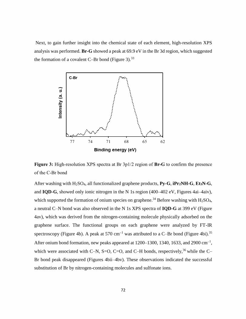
72
Next, to gain further insight into the chemical state of each element, high-resolution XPS
analysis was performed. Br-G showed a peak at 69.9 eV in the Br 3d region, which suggested
the formation of a covalent C–Br bond (Figure 3).33
Figure 3: High-resolution XPS spectra at Br 3p1/2 region of Br-G to confirm the presence
of the C-Br bond
After washing with H2SO4, all functionalized graphene products, Py-G, iPr2NH-G, Et3N-G,
and IQD-G, showed only ionic nitrogen in the N 1s region (400–402 eV, Figures 4ai–4aiv),
which supported the formation of onium species on graphene.34 Before washing with H2SO4,
a neutral C–N bond was also observed in the N 1s XPS spectra of IQD-G at 399 eV (Figure
4av), which was derived from the nitrogen-containing molecule physically adsorbed on the
graphene surface. The functional groups on each graphene were analyzed by FT-IR
spectroscopy (Figure 4b). A peak at 570 cm1 was attributed to a C–Br bond (Figure 4bi).35
After onium bond formation, new peaks appeared at 1200–1300, 1340, 1633, and 2900 cm1,
which were associated with C–N, S=O, C=O, and C–H bonds, respectively,36 while the C–
Br bond peak disappeared (Figures 4bii–4bv). These observations indicated the successful
substitution of Br by nitrogen-containing molecules and sulfonate ions.

73
Figure 4: (a) N1s XPS raw data (dotted line) and deconvolution (continuous line) for (i) Py-
G, (ii) Et3N-G, (iii) iPr2NH-G, (vi) IQD-G, and (v) IQD-G without acid washing. (b) FT-
IR spectra of (i) Br-G, (ii) Py-G, (iii) iPr2NH-G, (vi) Et3N-G, and (v) IQD-G
To obtain more information on the structure of the functionalized graphene, Raman spectra
were obtained. Two major peaks corresponding to the defect (D-band, at 1340 cm1) and
graphene (G-band, at 1570 cm1) domains were found in all Raman spectra (Figure 5 (i-v)).
The intensity ratio of these bands (ID/IG) can be used to indicate the density of defects present
in the graphene framework. The ID/IG ratio for Br-G was 1.5, and the other functionalized
graphenes, Py-G, iPr2NH-G, Et3N-G, and IQD-G, showed similar values. This suggested
that graphene had been selective functionalized by the nitrogen-containing molecules.

74
Figure 5: Raman analysis of (i) Br-G, (ii) Py-G, (iii) iPr2NH-G, (iv) Et3N-G, and (v) IQD-
G
For comparison, we also prepared chlorinated graphene (Cl-G) and iodinated graphene (I-
G) and investigated the formation of onium bond. The formation of halogenated graphene
was confirmed by EDS analysis (Figure 6 (a-c)). Cl-G contains 0.5% chlorine, Br-G contains
1.8% bromine and I-G contains 1.5% iodine (Table 3). The presence of halogen atom in EDS
spectra confirmed the synthesis of halogenated graphene. The formation of onium bond was
further confirmed by XPS analysis. The wide scan XPS spectra showed the presence of
nitrogen atom, confirming the formation of onium bonding (Figure 7). The amount of
nitrogen in Cl-G, Br-G, and I-G was 0.8%, 2.5% and 0.7% respectively (Table 4). The high-
resolution N 1s XPS spectra showed that Br-G predominantly formed the onium bond as
compared to other halogenated graphene (Figure 8).
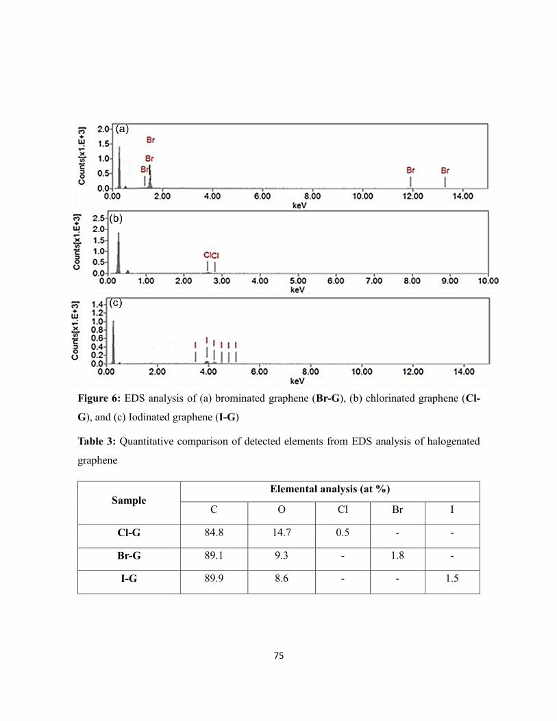
75
Figure 6: EDS analysis of (a) brominated graphene (Br-G), (b) chlorinated graphene (Cl-
G), and (c) Iodinated graphene (I-G)
Table 3: Quantitative comparison of detected elements from EDS analysis of halogenated
graphene
Sample Elemental analysis (at %)
C O Cl Br I
Cl-G 84.8 14.7 0.5 - -
Br-G 89.1 9.3 - 1.8 -
I-G 89.9 8.6 - - 1.5

76
Figure 7: Wide scan XPS spectra of IQD-G prepared from, (i) IQD-G (Cl), (ii) IQD-G (Br),
and (iii) IQD-G (I)
Table 4: Elemental analysis by XPS analysis
Sample Elemental analysis (at %)
C O N S Cl Br I
IQD-G (Cl) 77.6 20.5 0.8 0.7 0.3 - -
IQD-G (Br) 70.3 24.6 2.5 2.4 - - -
IQD-G (I) 81.2 17.4 0.7 0.6 - - 0.5

77
Figure 8: High-resolution XPS spectra at N 1s region of IQD-G prepared from, (i) IQD-G
(Cl), (ii) IQD-G (Br), and (iii) IQD-G (I)
Functionalized graphenes are expected to work as electrode.37 To show the proof of the
concept of our strategy, graphene functionalized with a redox-active molecule, IQD-G, was
evaluated as an electrode in biofuel cell, SCs, and LIBs applications mainly in the viewpoint
of stability (e.g., leaching of IQD) in the following sections.
3.2.1. Biofuel cell application
Initially, the performance of the IQD-G electrode was evaluated in a biofuel cell.
Power curves were obtained by scanning from the open-circuit voltage (OCV) of the cell to
0 V at a constant scan rate of 1 mV s1 in Phosphate buffer saline (PBS) solution containing
1 mol L1 D-glucose. As a result, a power density of 47.7 W cm-2 was obtained (Figure 9).
After 2 h, the power density of the IQD-G electrode had decreased to 50%. This decrease
was due to the decomposition of IQD. In contrast, the power density of a biofuel cell
composed of an electrode prepared by simply mixing IQD and graphene was reduced to 20%

78
(Figure 10). Therefore, IQD-G showed better stability and improved performance compared
with a just mixed sample of IQD, and graphene (IQD-graphene mixture), confirming the
usefulness of onium bond formation. Furthermore, the non-catalytic cyclic voltammograme
(CV) of IQD-G was measured at different scan rates (Figure 11a). The current was
proportionally increased as the scan rate increased. The IQD-G showed narrower Ep than
the electrode prepared by just mixing of graphene and IQD (Figure 11b), suggesting a
successful electron transfer of IQD-G. Further, the effect of flavin adenine dinucleotide-
glucose dehydrogenase (FAD-GDH) and glucose on the biofuel cell performance of IQD-D
was investigated (Figure 12a and 12b).
Figure 9: Power density vs voltage

79
Figure 10: The power density of biofuel cells derived from (i) IQD-G, and (ii) a simple
mixture of IQD with graphene after different time intervals in PBS–glucose solution (1 M)
at a scan rate of 1 mV s1
Figure 11: Cyclic voltammogram of (a) IQD-G, and (b) mixing of graphene and IQD
without glucose at different scan rate using PBS (0.5 M) as electrolyte
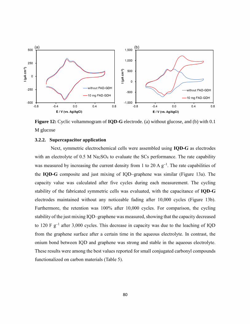
80
Figure 12: Cyclic voltammogram of IQD-G electrode. (a) without glucose, and (b) with 0.1
M glucose
3.2.2. Supercapacitor application
Next, symmetric electrochemical cells were assembled using IQD-G as electrodes
with an electrolyte of 0.5 M Na2SO4 to evaluate the SCs performance. The rate capability
was measured by increasing the current density from 1 to 20 A g1. The rate capabilities of
the IQD-G composite and just mixing of IQD–graphene was similar (Figure 13a). The
capacity value was calculated after five cycles during each measurement. The cycling
stability of the fabricated symmetric cells was evaluated, with the capacitance of IQD-G
electrodes maintained without any noticeable fading after 10,000 cycles (Figure 13b).
Furthermore, the retention was 100% after 10,000 cycles. For comparison, the cycling
stability of the just mixing IQD–graphene was measured, showing that the capacity decreased
to 120 F g1 after 3,000 cycles. This decrease in capacity was due to the leaching of IQD
from the graphene surface after a certain time in the aqueous electrolyte. In contrast, the
onium bond between IQD and graphene was strong and stable in the aqueous electrolyte.
These results were among the best values reported for small conjugated carbonyl compounds
functionalized on carbon materials (Table 5).
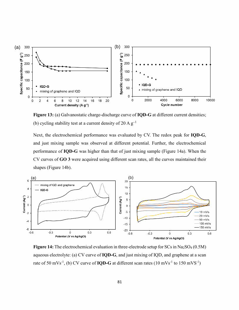
81
Figure 13: (a) Galvanostatic charge-discharge curve of IQD-G at different current densities;
(b) cycling stability test at a current density of 20 A g1
Next, the electrochemical performance was evaluated by CV. The redox peak for IQD-G,
and just mixing sample was observed at different potential. Further, the electrochemical
performance of IQD-G was higher than that of just mixing sample (Figure 14a). When the
CV curves of GO 3 were acquired using different scan rates, all the curves maintained their
shapes (Figure 14b).
Figure 14: The electrochemical evaluation in three-electrode setup for SCs in Na2SO4 (0.5M)
aqueous electrolyte: (a) CV curve of IQD-G, and just mixing of IQD, and graphene at a scan
rate of 50 mVs-1, (b) CV curve of IQD-G at different scan rates (10 mVs-1 to 150 mVS-1)

82
Table 5: Comparison of IQD-G with the published data for quinone-containing carbon-based
electrodes
3.2.3. Lithium-ion battery application
Finally, the performance of the IQD-G electrode and mixed graphene–IQD electrode
were comparatively evaluated in a half-cell LIBs. The charge-discharge behavior of the IQD-
G coin cell between 1.5 and 4.3 V at 10 mA g1 showed a discharge plateau at 3.2 V and
expressed a reversible capacity of 118 mAh g1(Figure 15a), while just mixing of IQD and
graphene sample showed no discharge plateau and a reversible capacity as low as 40 mAh
g1 (Figure 15b). This absence of a plateau and lower capacity demonstrated that just mixing
of IQD and graphene sample was inactive for LIBs. The rate capability evaluation showed
Electrode
material Electrolyte
Retention (%)
(cycle number)
Current
density/scan rate Ref.
TBHQ@gr 1 M H2SO4 92 (800) 1 A g−1 [38]
AQ@CFs 1 M H2SO4 89 (5000) 20 A g−1 [39]
AQ@gr 1 M HCl 77 (10 000) 10 A g−1 [40]
AT@AC 1 M H2SO4 90 (1000) 200 mA g−1 [41]
HQ@gr 1 M H2SO4 86 (10 000) 10 A g−1 [42]
PQ@OLC 1 M H2SO4 90 (10 000) 200 mV s−1 [43]
NQ@OLC 1 M H2SO4 92 (10 000) 50 mV s−1 [44]
PQ@AC 1M KOH 80 (1000) 2 A g−1 [45]
HQ@AC 1 M H2SO4/HQ 65 (4000) 4.42 mA cm−2 [46]
Catechol/AC 1 M H2SO4 75 (10 000) 7.5 A g−1 [47]
BPA/gr. 1 M H2SO4 90 (4000) 1 A g−1 [48]
AQ/gr 1 M H2SO4 97 (2000) 10 A g−1 [49]
RGO/AQDS 1 M H2SO4 82 (10,000) 1 A g−1 [50]
THAQ/RGO 1 M H2SO4 97 (10,000) 1 A g−1 [51]
IQD/gr 0.5 M Na2SO4 100 (10,000) 20 Ag-1 This work

83
that IQD-G still exhibited a capacity of 30 mAh g1 at 1 A g1, while just mixing of IQD and
graphene showed a capacity of only 13 mAh g1 at the same rate (Figure 16a). The cyclability
study at 1 A g1 showed that IQD-G remained stable, highlighting the stability of the onium
bonding for LIBs (Figure 16b). These results demonstrated that onium bonding has great
potential for use in high-performance LIB electrodes. The above electrical applications
demonstrated the superior electrode performance of IQD-G compared with just mixing of
IQD and graphene.
Figure 15: LIB charge-discharge behavior of (a) IDQ-G, and (b) mixing of graphene and
IDQ at 10 mA g-1
Figure 16: (a) Galvanostatic charge-discharge curve of IQD-G at different current
densities; (b) cycling stability test at a current density of 1 A g1

84
The difference between these two materials was investigated by soaking each electrode
material in organic and aqueous electrolyte solutions for 2 h, and then analyzing the eluted
IQD by UV–Vis spectroscopy (Figure 17a and 17b). The results showed that onium bonding
prevented the release of IQD into the electrolyte, allowing superior performance.
Figure 17: UV/Vis measurement of leached IQD from an electrode prepared by mixing IQD
and graphene, and IQD-G; (a) Leaching test in aqueous electrolyte (Na2SO4). (b) Leaching
test in an organic electrolyte (diethyl carbonate)

85
3.3. Conclusions
We have produced functional graphenes with strong onium bonding. This
functionalization can be achieved by simply mixing brominated graphene with nitrogen-
containing molecules. Graphene functionalized with a redox-active molecule was evaluated
as an electrode in biofuel cell, SCs, and LIBs applications, exhibiting excellent
electrochemical performance. Among applications such as LIBs, SCs, and biofuel cell, SCs
was found to be promising. The high SCs performance is due to the synergistic effect of IQD
and graphene which act as pseudo-capacitance and EDLC at the same time. Stability of the
LIB using IQD-G was acceptable, but capacity was low due to the small amount of IQD
molecule on graphene. IQD-G worked also as an electrode for a biofuel cell, however,
stability was not adequate due to the decomposition of IQD moiety during enzymatic reaction.
The performance of biofuel cell can be improved by optimizing the structure of redox-active
molecules by attaching substituents or linkers to improve the stability and electron transfer
efficiency. Although further improvement is needed, functionalized graphene through onium
bonding will provide the long-lasting performance required for future practical applications.
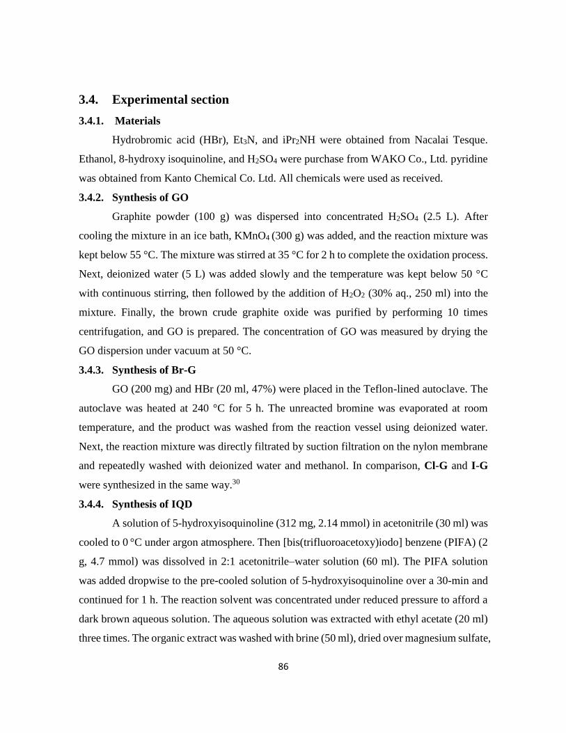
86
3.4. Experimental section
3.4.1. Materials
Hydrobromic acid (HBr), Et3N, and iPr2NH were obtained from Nacalai Tesque.
Ethanol, 8-hydroxy isoquinoline, and H2SO4 were purchase from WAKO Co., Ltd. pyridine
was obtained from Kanto Chemical Co. Ltd. All chemicals were used as received.
3.4.2. Synthesis of GO
Graphite powder (100 g) was dispersed into concentrated H2SO4 (2.5 L). After
cooling the mixture in an ice bath, KMnO4 (300 g) was added, and the reaction mixture was
kept below 55 °C. The mixture was stirred at 35 °C for 2 h to complete the oxidation process.
Next, deionized water (5 L) was added slowly and the temperature was kept below 50 °C
with continuous stirring, then followed by the addition of H2O2 (30% aq., 250 ml) into the
mixture. Finally, the brown crude graphite oxide was purified by performing 10 times
centrifugation, and GO is prepared. The concentration of GO was measured by drying the
GO dispersion under vacuum at 50 °C.
3.4.3. Synthesis of Br-G
GO (200 mg) and HBr (20 ml, 47%) were placed in the Teflon-lined autoclave. The
autoclave was heated at 240 °C for 5 h. The unreacted bromine was evaporated at room
temperature, and the product was washed from the reaction vessel using deionized water.
Next, the reaction mixture was directly filtrated by suction filtration on the nylon membrane
and repeatedly washed with deionized water and methanol. In comparison, Cl-G and I-G
were synthesized in the same way.30
3.4.4. Synthesis of IQD
A solution of 5-hydroxyisoquinoline (312 mg, 2.14 mmol) in acetonitrile (30 ml) was
cooled to 0 °C under argon atmosphere. Then [bis(trifluoroacetoxy)iodo] benzene (PIFA) (2
g, 4.7 mmol) was dissolved in 2:1 acetonitrile–water solution (60 ml). The PIFA solution
was added dropwise to the pre-cooled solution of 5-hydroxyisoquinoline over a 30-min and
continued for 1 h. The reaction solvent was concentrated under reduced pressure to afford a
dark brown aqueous solution. The aqueous solution was extracted with ethyl acetate (20 ml)
three times. The organic extract was washed with brine (50 ml), dried over magnesium sulfate,

87
filtered, and concentrated under reduced pressure to give a dark yellow residue. The residue
was purified by silica gel column chromatography eluting with 1:4 ethyl acetate–hexanes to
give 160 mg (51%) IQD as bright yellow crystals.52 1H NMR (300 MHz, CDCl3) 9.36 (S,
1H), 9.10 (d, J= 2.1Hz, 1H), 7.87 (d, J= 2.1Hz, 1H), 7.00 (m, 2H).
3.4.5. Br-G substitution with iPr2NH and Et3N
Br-G dispersion was prepared by adding Br-G (100 mg) into ethanol (20 ml), which
was sonicated for 30 min. Then the dispersion was injected to the flask, and to this was added
Et3N (0.681 ml, 0.5 mmol). The mixture solution was stirred for three days at 70 °C. After
completion of the reaction, solid product was filtered, washed with H2SO4 and distilled water
several times, respectively.
3.4.6. Br-G substitution with pyridine
In a typical experiment, Br-G (100 mg) was sonicated for 30 minutes in ethanol (50
ml) to obtain fine dispersion. To this dispersion, pyridine (51 µl, 0.632 mmol) was added.
The mixture solution was then refluxed for 40 h with constant stirring. After completion of
the reaction, the mixture solution was filtered and washed with sulfuric acid and distilled
water respectively.
3.4.7. Br-G substituted with IQD:
Br-G (100 mg) and IQD were added to the flask containing ethanol (50 ml), which
was sonicated for 30 minutes. The dispersion was then refluxed for 40 h under constant
stirring. After completion of the reaction, the mixture solution was filtered and washed a few
times with sulfuric acid and water, respectively, to obtain the final product.
3.4.8. Characterization
FT-IR were recorded on a SHIMADZU IR Tracer-100 in the range of 500-4500 cm-
1. The samples for FT-IR were dried and mixed with KBr, and then pressed up to 1.3 mm-
diameter pellets. The XPS was carried out on a JPS-9030 with a pass energy of 20 eV. Raman
spectroscopic measurements were conducted at room temperature by a Raman spectrometer.
The UV-Vis measurements were conducted on a JASCO V-670 spectrophotometer. SEM-
EDS was performed using JSM-IT 100 LA.

88
3.4.9. Electrochemical characterization:
For biofuel cell, the anode was fabricated by mixing electrode material (16 mg) and
carbon black (1.8 mg) in 1 mL NMP, which is sonicated to make fine dispersion. Then 3 L
suspension using a pipet gun was dropped onto the glassy carbon electrode (diameter: 3 mm)
and completely dried at 50 °C in vacuo for 1 h. The cathode used a curled platinum wire.
Using a dialysis membrane, the anode and the cathode were separated, then phosphate buffer
(PBS, pH = 7, 25 mL) was added to the cathode side, the PBS solution of 1 mol L-1 D-glucose
(25 mL) was added to the anode side. In addition, O2 bubbling was performed on the cathode
side and the 10 mg enzyme (FAD-GDH) was added to the anode side. The power curves
were obtained by scanning the voltage between the OCV of the cell to 0 V at a constant scan
rate of 1 mV s−1. To confirm the correctness of the data, we performed power density
measurement of IQD-G for three times, as a result, 47.7±4.3 W (n=3) were obtained.
For SCs the working electrode was prepared by mixing electrode material (40 mg), carbon
black (5 mg), and PVDF (5 mg) in NMP (2 mL), which was sonicated for 1 h. The prepared
past was then coated on nickel foil and dried under vacuum at 50 °C for 24 h. The
electrochemical performance was tested in a two-electrode system separated by a glass fiber
membrane. The cycling test and rate capability test are evaluated by charge/discharge
measurement with a potential range from 0-1 V. Specific capacitance of the SCs (C, F g-1) is
calculated from discharge curve according to the following formula:
C =2 I • Δt
m • ΔV
where I is the constant current in discharging, m is the mass of active material on working
electrode, Δt is the discharge time, and ΔV is the voltage change during discharge. The rate
capability and cycling stability test was measured in 0.5 M Na2SO4 electrolyte solution with
a Solartron SI1287 electrochemical workstation.
In the three-electrode system, the platinum foil and Ag/AgCl electrode were used as the
counter electrode and reference electrode, respectively. The working electrode was fabricated
by mixing electrode material (20 mg) and carbon black (2.2 mg) in 1 mL NMP solution,

89
which is sonicated to make fine dispersion. Then 3 μL above suspension using a pipet gun
was dropped onto the glassy carbon electrode (5 mm) and completely dried at 50 °C for 1 h
under vacuum. The electrochemical performance was measured in a potential range of -0.6-
0.5 V, with a scan rate of 50 mVs-1. To confirm the correctness of the data, we performed
capacitance measurement of IQD-G for three times at 20 A g-1, as a result, 200± 6 F g-1 (n=3)
were obtained.
For LIBs battery the working electrodes were made of active material: carbon black: PVDF=
7: 2: 1 by using NMP as a solvent and a copper foil as the current collector. For both IQD-
G and just mixing of IQD and graphene, the amount of IQD was adjusted to 17 wt%. In order
to obtain the homogeneous active and conductive material powder, both materials were
mixed together in a distilled water-ethanol solution (v/v, 1/1). After mixing, the solution was
filtered using Merck Millipore JAWP04700 filter. The powder was freeze and then freeze-
dry under vacuum at 30 °C for 24 h. The dry powder was set into ball-milling for 30 min at
300 RPM to reduce the particle size. Then the powder was at first mixed with NMP to obtain
a homogeneous slurry and then with the binder. The slurry (active material, a conductive
material, binder) was spread on a copper foil using a Doctor blade of 100 µm. The sheet was
dry under vacuum at atmospheric temperature for 24 h and in air at 120 °C for 20 min. Finally,
the 15.95 mm sheets were punched and pressed. To confirm the correctness of the data, we
performed a capacity measurement of IQD-G for three coin-cells at 1 A g-1. As a result,
30.8±1.3 mAh g1 (n=3) were obtained.
3.4.10. Electrode sheet preparation for LIBs
The working electrodes were made of active material: carbon black: PVDF= 7: 2:
1 by using NMP as a solvent and aluminum foil as the current collector. The powder was at
first mixed with NMP to obtain a homogeneous slurry and then with the binder. The slurry
(mixture of active material, conductive material, and binder) was spread on aluminum foil
using a Doctor blade of (100 µm thickness). The sheet was dry dried under vacuum at
atmospheric room temperature for 24 h and in air and at 120 °C for 20 min. Finally, the sheets
with a diameter of 15.95 mm were punched and pressed.
90
3.4.11. Preparation of LIBs
The LIB was assembled in an argon-filled glow box using our electrode at the
cathode, lithium foil at the anode, a Whatman 1823-257 as separator, 70 µl electrolyte. The
electrolyte was 1 M L-1 LiPF6 dissolved in a mixture of ethylene carbonate, diethyl carbonate
(v/v, 3/7).
3.4.12. Evaluation of LIBs
The charge and discharge cycling tests were performed using a multi-channel
battery tester (580 8 channel Battery Cycler Scribner Associates Incorporated) with a voltage
window of 1.5 - 4.3 V. Each cell was subject to charge-discharge cycle at different current
rates: 0.01C, 0.05C, 0.1C, 1C. All currents have been calculated with 1C = 1 A g-1.

91
3.5. References
1. S. Chandrasekaran, N. Sato, F. Tölle, R. Mülhaupt, B. Fiedler, K. Schulte,. Compos. Sci.
Technol. 2014, 97, 90–99.
2. Y. Qian, I. M. Ismail, A. Stein, A, Carbon, 2014, 68, 221–231.
3. C. Zheng, X. Zhou, H. Cao, G. Wang, Z. Liu, J. Power Sources 2014, 258, 290–296.
4. A. Klechikov, G. Mercier, T. Sharifi, I. A. Baburin, G. Seifert, A. V. Talyzin, Chem.
Commun. 2015, 51, 15280–15283.
5. R. Xiong, K. Hu, A. M. Grant, R. Ma, W. Xu, C. Lu, X. Zhang, V. V. Tsukruk, Adv. Mater.
2016, 28, 1501–1509.
6. H. Murata, Y. Nakajima, N. Saitoh, N. Yoshizawa, T. Suemasu, K. Toko, Sci. Rep. 2019,
9, 1–5.
7. M. Cao, D. B. Xiong, L. Yang, S. Li, Y. Xie, Q. Guo, Z. Li, H. Adams, J. Gu, T. Fan, X.
Zhang, D. Zhang, Adv. Funct. Mater. 2019, 29, 1806792.
8. X. Xu, L. F. C. Pereira, Y. Wang, J. Wu, K. Zhang, X. Zhao, S. Bae, C. T. Bui, R. Xie, J.
T. L. Thong, B. H. Hong, K. P. Loh, D. Donadio, B. Li, B. Ozyilmaz, Nat. Commun. 2014,
5, 3689.
9. A. Balandin, Nat. mater. 2011, 10, 569–581.
10. S. Kawai, S. Saito, S. Osumi, S. Yamaguchi, A. S. Foster, P. Spijker, E. Meyer, Nat.
Commun. 2015, 6, 8098.
11. D. Usachov, O. Vilkov, A. Grüneis, D. Haberer, A. Fedorov, V. K. Adamchuk, A. B.
Preobrajenski, P. Dudin, A. Barinov, M. Oehzelt, C. Laubschat, D. K. Vyalikh, Nano Lett.
2011, 11, 5401–5407.
12. J. Li, S. Zhang, C. Chen, G. Zhao, X. Yang, J. Li, X. Wang, ACS Appl. Mater. Interfaces.
2012, 4, 4991–5000.
13. F. Parnianchi, M. Nazari, J. Maleki, M. Mohebi, Int. Nano Lett. 2018, 8, 229–239.
14. B. He, Q. Tang, M. Wang, C. Ma, S. Yuan, J. Power Sources 2014, 256, 8–13.
15. J. Liu, J. Tang, J. J. Gooding, J. Mater. Chem. 2012, 22, 12435–12452.
16. P. Katti, K. V. Kundan, S. Kumar, S. Bose, Polymer 2017, 122, 184–193.
92
17. V. Georgakilas, M. Otyepka, A. B. Bourlinos, V. Chandra, N. Kim, K. C. Kemp, P.
Hobza, R. Zboril, K. S. Kim, Chem. Rev. 2012, 112, 6156–6214.
18. A. Keerthi, B. Radha, D. Rizzo, H. Lu, V. D. Cabanes, I. C. Y. Hou, D. Beljonne, J.
Cornil, C. Casiraghi, M. Baumgarten, K. Mullen, J. Am. Chem. Soc. 2017, 139, 16454–
16457.
19. X. Y. Wang, X. Yao, K. Müllen, Era. Sci. China Chem. 2019, 62, 1099–1144.
20. S. Eigler, A. Hirsch, Phys. Sci. Rev. 2017, 2, 30-66.
21. G. Bottari, M. A. Herranz, L. Wibmer, M. Volland, L. Rodríguez-Pérez, D. M. Guldi, A.
Hirsch, N. Martín, F. D’Souza, T. Torres, Chem. Soc. Rev. 2017, 46, 4464–4500.
22. H. Au, N. Rubio, M. S. P. Shaffer, Chem. Sci. 2017, 9, 209–217.
23. S. Eigler, Chem. Eur. J. 2016, 22, 7012–7027.
24. Z. Liu, H. Zhou, Z. Huang, W. Wang, F. Zeng, Y. Kuang, J. Mater. Chem. A 2013, 1,
3454–3462.
25. Y. Liang, D. Wu, X. Feng, K. Müllen, Adv. Mater. 2009, 21, 1679–1683.
26. M. Fang, K. Wang, H. Lu, Y. Yang, S. Nutt, J. Mater. Chem. 2009, 19, 7098–7105.
27. C. C. Teng, C. C. M. Ma, C. H. Lu, S. Y. Yang, S. H. Lee, M. C. Hsiao, M. Y. Yen, K.
C. Chiou, T. M. Lee, Carbon 2011, 49, 5107–5116.
28. J. Balapanuru, J. X. Yang, S. Xiao, Q. Bao, M. Jahan, L. Polavarapu, J. Wei, Q. H. Xu,
K. P. A. Loh, Angew. Chem. Int. Ed. 2010, 49, 6549–6553.
29. V. Georgakilas, J. N. Tiwari, K. C. Kemp, J. A. Perman, A. B. Bourlinos, K. S. Kim, R.
Zboril, Chem. Rev. 2016, 116, 5464–5519.
30. S. Bag, A. Samanta, P. Bhunia, C. R. Raj, Int. J. Hydrog. Energy 2016, 41, 22134–22143.
31. O. Jankovský, P. Šimek, K. Klimová, D. Sedmidubský, S. Matějková, M. Pumera, Z.
Sofer, Nanoscale 2014, 6, 6065–6074.
32. S. Lai, Y. Jin, X. Sun, J. Pan, W. Du, L. Shi, Res. Chem. Intermed. 2018, 44, 3523–3536.
33. H. Li, Y. Shi, L. J. Li, Carbon 2018, 127, 602–610.
34. X. Hu, X. Lin, H. Zhao, Z. Chen, J. Yang, F. Li, C. Liu, F. Tian, Materials, 2016, 9, 376.
35. G. Shukla, V. K. Shahi, Sustain. Energy Fuels 2017, 1, 932–940.

93
36. J. Ederer, P. Janoš, P. Ecorchard, J. Tolasz, V. Štengl, H. Beneš, M. Perchacz, P.
Georgievski, RSC Adv. 2017, 7, 12464–12473.
37. M. Liang, L. Zhi, J. Mater. Chem. 2009, 19, 5871-5878.
38. H. Wang, H. Wu, Y. Chang, Y. Chen, Z. Hu, Chin. Sci. Bull. 2011, 56, 2092–2097.
39. H. Wang, H. Yi, C. Zhu, X. Wang, H. J. Fan, Nano Energy 2015, 13, 658–669.
40. P. G. Campbell, M. D. Merrill, B. C. Wood, E. Montalvo, M. A. Worsley, T. F. Baumann,
J. Biener, J. Mater. Chem. A 2014, 2, 17764–17770.
41. S. Isikli, R. Díaz, Carbon. J. Power Sources 2012, 206, 53–58.
42. Y. Xu, Z. Lin, X. Huang, Y. Wang, Y. Huang, X. Duan, Adv. Mater. 2013, 25, 5779–
5784.
43. M. Zeiger, D. Weingarth, V. Presser, Chem. Electro. Chem. 2015, 2, 1117–1127.
44. D. M. Anjos, J. K. McDonough, E. Perre, G. M. Brown, S. H. Overbury, Y. Gogotsi, V.
Presser, Nano Energy 2013, 2, 702–712.
45. A. L. Comte, D. Chhin, A. Gagnon, R. Retoux, T. Brousse, D. Bélanger, J. Mater. Chem.
A 2015, 3, 6146–6156.
46. S. Roldán, C. Blanco, M. Granda, R. Menéndez, R. Santamaría, Angew. Chem. Int. Ed.
2011, 50, 1699–1701.
47. G. Pognon, C. Cougnon, D. Mayilukila, D. Bélanger, ACS Appl. Mater. Interfaces 2012,
4, 3788–3796.
48. H. Hu, Z. Hu, X. Ren, Y. Yang, R. Qiang, N. An, H. Wu, Chinese J. Chem. 2015, 33,
199–206.
49. N. An, F. Zhang, Z. Hu, Z. Li, L. Li, Y. Yang, B. Guo, Z. Lei, RSC Adv. 2015, 5, 23942–
23951.
50. L. Gao, S. Gan, H. Li, D. Han, F. Li, Y. Bao, L. Niu, Nanotechnol, 2017, 28, 275602.
51. L. Xu, R. Shi, H. Li, C. Han, M. Wu, C. P. Wong, F. Kang, B. Li, Carbon 2018, 127,
459–468.
52. M. Paige, G. Kosturko, G. Bulut, M. Miessau, S. Rahim, J. A. Toretsky, M. L. Brown, A.
Uren, Bioorg. Med. Chem. 2014, 22, 478–487.

94
Chapter: 4
Grafting conductive polymers on graphene oxide
through cross-linker: a stepwise approach
95
Abstract ………………………………………………………………………….. 96
4.1. Introduction …………………………………………………………………. 96
4.2. Results and Discussion ……………………………………………………... 98
4.2.1. Electrochemical performance as a supercapacitor ……………………….. 107
4.3. Conclusion ………………………………………………………………….. 114
4.4. Experimental section ………………………………………………………. 115
4.4.1. Materials …………………………………………………………………. 115
4.4.2. Synthesis of GO …………………………………………………………. 115
4.4.3. Preparation of N,N-bissulphinyl-m-benzenediamine (m-monomer) ……. 115
4.4.4. Synthesis of GO 1 ………………………………………………………. 115
4.4.5. Synthesis of GO 2 ………………………………………………………. 116
4.4.6. Synthesis of GO 3 ………………………………………………………. 116
4.4.7. Structural characterization ……………………………………………… 116
4.4.8. Electrochemical characterization ……………………………………….. 117
4.5. References ………………………………………………………………… 118

96
Abstract: A three-step reaction furnished a composite of graphene and a conductive
polymer. In the first step, GO was modified with a diamine, which acted as a linker for
polymer attachment. In the second step, an initiating site was attached to the free amine of
the linker. Finally, a polymer was grown from the initiation site, and GO was reduced during
polymer growth. The method does not require any catalyst, acid, or reducing agent,
furnishing the graphene–polymer composite in a straightforward procedure. Various
instrumental techniques, including step-by-step AFM analysis, were used to characterize the
structure of the products in each step and confirm the covalent functionalization among GO,
cross-linker, and polymer. The average surface height was sequentially increased after each
step, indicating the success of the sequential reactions. The graphene-polymer composite
showed excellent electrochemical performance and stability compared with a composite
prepared by physical mixing of graphene and polymer.
4.1. Introduction
Among the many proposed applications of graphene-based materials, SCs, also
known as electrochemical capacitors, have been an active area of research for the past
decade.1–3 Compared with secondary batteries, graphene based SCs are electrochemical
energy storage devices that promise outstanding power density,4 charge/discharge rate,5
cycling stability,6 and operational safety.7 SCs are often utilized individually or in tandem
with batteries for energy storage and supply (Figure 1ai). They can be classified into two
types: the electric double-layer capacitor (EDLC) (Figure 1aii) and the pseudocapacitor
(Figure 1aiii). The energy storage mechanism of the EDLC involves a simple charge
separation at the interface between the conductive electrode and the electrolyte. Because
there is no chemical transformation at the EDLC electrodes, the system is quite stable,
although the specific capacitance is relatively low.8,9 In comparison, charge storage in a
pseudocapacitor is predominantly achieved via the redox or faradic transformation of
capacitive electrode materials, such as metal oxides10 and conductive polymers.11 The
specific capacitance of the pseudocapacitor is generally high, but gradually decays because
of structural collapse and degradation. A composite of a conductive substance and a

97
pseudocapacitive material is desirable to enhance the overall capacitance, charge/discharge
rate, and cycling lifetime. Graphene is a promising conductive component because it has a
large surface area,12-14 and excellent electronic15,16 and mechanical properties.17,18 To develop
a high-performance pseudocapacitor, we focused on developing a conductive polymer as an
electrode counterpart to graphene. Various graphene–polymer composites with non-covalent
and covalent interactions have been synthesized, and high capacitive performances have been
achieved. The non-covalent interaction between graphene and polymers limits charge
transfer at their interface, and hence constrains the cycling stability (Figure 1bi).19 To address
this issue, we propose the formation of the covalent bond between graphene and redox-active
polymers.
Liu covalently functionalized graphene using amidation to graft phenylenediamine to
chlorinated GO, followed by polymerization and reduction.20 Gao,21 Baek,22 Liu,23 and Shen,
24 independently reported the covalent grafting of polyaniline to graphene; all these methods
initially functionalized graphene with phenylenediamine, then added aniline to initiate
polymerization under acidic and oxidative conditions (Figure 1bii). As a result, a covalently
cross-linked graphene–polymer composite was formed. Herein, I synthesized a new type of
composite containing a linker between the polymer and graphene (Figure 1biii). The
graphene–polymer composite was synthesized using a three-step reaction involving a cross-
linker, initiator, and monomer. The prepared polymer–graphene composite was used as an
electrode material for a SCs.

98
Figure 1: (a) (i) SCs systems, (ii) EDLC-type carbon materials, and (iii) pseudocapacitor-
type conductive polymer or metals. (b) Synthesis of graphene-polymer through (i) non-
covalent bond, (ii) covalent bond, and (iii) present work: covalent bond with cross-linker
4.2. Results and Discussion
Our strategy to synthesize a graphene–polymer composite with a linker (GO 3) involved
three steps: (1) functionalization of graphene with 1,3-diaminopropane to obtain GO 1; (2)
addition of a monomer (N,N’-bissulphinyl-m-benzenediamine) to GO 1 to obtain GO 2; (3)
addition of another monomer (1,4-phenylenediamine) to GO 2 to initiate polymerization
(Figure 2). The polymer synthesis25 and amine functionalization of GO26 were independently
reported, and we prepared GO 1, GO 2, and GO 3 following these previous reports.
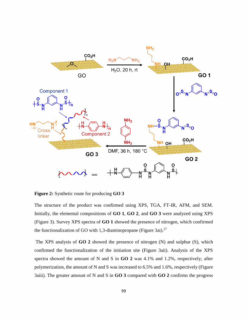
99
Figure 2: Synthetic route for producing GO 3
The structure of the product was confirmed using XPS, TGA, FT-IR, AFM, and SEM.
Initially, the elemental compositions of GO 1, GO 2, and GO 3 were analyzed using XPS
(Figure 3). Survey XPS spectra of GO 1 showed the presence of nitrogen, which confirmed
the functionalization of GO with 1,3-diaminopropane (Figure 3ai).27
The XPS analysis of GO 2 showed the presence of nitrogen (N) and sulphur (S), which
confirmed the functionalization of the initiation site (Figure 3aii). Analysis of the XPS
spectra showed the amount of N and S in GO 2 was 4.1% and 1.2%, respectively; after
polymerization, the amount of N and S was increased to 6.5% and 1.6%, respectively (Figure
3aiii). The greater amount of N and S in GO 3 compared with GO 2 confirms the progress

100
of the polymerization. The amount of oxygen in GO 1, GO 2, and GO 3 was 25.6%, 17.5%,
and 11.0%, respectively (Table 1). The smaller amount of oxygen in GO 3 suggested
reduction of GO occurred during heating.
Figure 3: (a) Wide-scan X-ray photoelectron spectra of (i) GO 1, (ii) GO 2, and (iii) GO 3
Table 1: Quantitative comparison of detected elements from XPS spectra
Sample Element (at.%)
C O N S
GO 3 81.1 11.0 6.5 1.6
GO 2 76.6 17.5 4.1 1.2
GO 1 71.9 25.6 2.4 --

101
To gain further insight into the chemical composition, each element was analyzed using high-
resolution XPS (Figure 4). The spectrum of GO 1 showed a peak at 398.5 eV in the N 1s
region, which suggested the formation of a covalent C–N bond,28 and confirmed the
functionalization of GO with 1,3-diaminopropane (Figure 4a). Similarly, a new peak was
observed in the S 2p region of GO 3 at 163.5 eV, which could be attributed to a C–S=O bond
from the polymer (Figure 4c).29 These spectral changes indicate the successful grafting of the
polymer onto graphene.
Figure 4: High-resolution XPS spectra of (a) N 1s of (a) GO 1, (b) GO 2, (c) GO 3, and S
2p of (d) GO 2, and (e) GO 3
Next, the thermal stability of each material was measured using TGA (Figure 5a). The TGA
curve of GO showed that most weight loss occurred below 150 °C in the N2 atmosphere,
which was due to the removal of adsorbed water and oxygen-containing groups (Figure 5ai).
30 In the case of GO 1, a slow weight loss was observed, starting from 150–250 °C, due to
the thermal decomposition of remaining oxygenated functional groups and 1,3-

102
diaminopropane,31 from the GO (Figure 5aii). The lower weight loss observed in GO 1
compared with GO could be attributed to the partial reduction of GO by diamine, as reported
previously.32 The TGA curve of the pristine polymer suggested that the polymer decomposed
only gradually above 250 °C, with almost 50 wt% remaining even at 850 °C (Figure 5aiii).
Comparing the TGA curve of GO 3 with these data, the weight loss between 150 °C and
200 °C could be ascribed to the removal of oxygen functional groups and 1,3-
diaminopropane from GO, and the weight loss between 300 °C and 400 °C could be attributed
to the decomposition of the polymer (Figure 5aiv). Both of these observations suggest that
the polymer was successfully cross-linked to the graphene in GO 3.
The FT-IR spectrum of GO (Figure 5bi) revealed the presence of O–H (3435 cm1), C=O
(1735 cm1), C=C (1615 cm1), and C–O (1052 cm1) functional groups.33 The FT-IR
spectrum of GO 1 exhibited a peak at 2900 cm1, which was attributed to the alkyl chain of
1,3-diaminopropane (Figure 5bii).34 The spectrum GO 2 contained a small peak
corresponding to S=O at 1430 cm1, and the intensity of this peak was greater in the FT-IR
spectra of the pristine polymer,25 and GO 3.
Figure 5: (a) Thermogravimetric analysis of (i) GO, (ii) GO 1, (iii) polymer, and (iii) GO 3;
(b) FT-IR analysis of (i) GO, (ii) GO 1, (iii) GO 2, (iv) polymer, and (v) GO 3

103
The stepwise functionalization of graphene was confirmed by AFM (Figure 6). The average
height of GO was approximately 0.9 nm (Figure 6a). The height of a GO 1, and GO 2 was
1.3 nm, and 1.5 nm, respectively. The values are only slightly larger than that of the pristine
GO (Figure 6b and 6c); therefore, we consider 1,3-diaminopropane and/or N,N’-bissulphinyl-
m-benzenediamine are bent or almost horizontal to GO plane. The height of GO 3 was about
16 nm, much higher than others, due to the growth of polymer on graphene (Figure 6d). This
dramatic increase in the surface height of GO 3 proves the bonding of the polymer on the
surface of graphene.
Figure 6: Atomic force microscope image analysis of (a) GO, (b) GO 1, (c) GO 2, and (d)
GO 3

104
The morphologies of GO, GO 1, GO 2, and GO 3 were further analyzed using SEM, which
indicated that GO consisted of thin single-layer sheets (Figure 7a), and that these structures
were retained by GO 1 (Figure 7b), and GO 2 (Figure 7c) after their functionalization. These
observations were consistent with the AFM analyses. The SEM image of GO 3 showed a
spherical shape (Figure 7d), possibly because of the uniform growth and encapsulation of the
graphene by the polymer. GO is negatively charged, and the nitrogen groups on polymer
would be positively charged; therefore, ionic interaction would occur. The SEM images
showed good agreement with AFM images.
Figure 7: Scanning electron microscope images of (a) GO, (b) GO 1, (c) GO 2, and (d)
GO 3

105
Possible side reactions, such as neutralization of amine and N,N’-bissulphinyl-m-
benzenediamine with acidic functional groups on GO were observed (Figure 8 and 9). The
reaction was performed on molecular level and the reaction was confirmed by NMR
spectroscopy (Figure 10). After this, the direct reaction of monomer on GO, without 1,3-
diaminopropane as a cross-linker, was prepared by the same procedure, except the starting
material was GO instead of GO 1. The elemental composition of d-GO 2 (without using 1,3-
diaminopropane) and GO 2 (addition of 1,3-diaminopropane) was also measured by XPS
analysis (Figure 11). In the case of d-GO 2, the direct addition of monomer to GO caused
the decomposition of the monomer, which might be due to the effect of the carboxylic group
of GO. The percentage of each elements are listed in Table 2. In the case of GO 2, most of
the carboxylic group was neutralized by 1,3-diaminopropane in the first step, which
prevented the decomposition of monomer. Therefore, this result confirmed that the addition
of 1,3-diaminopropane in the first step is important.
Figure 8: Synthesis of GO 2, and d-GO 2
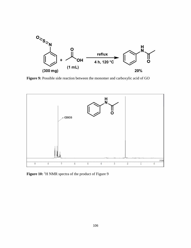
106
Figure 9: Possible side reaction between the monomer and carboxylic acid of GO
Figure 10: 1H NMR spectra of the product of Figure 9

107
Figure 11: Wide scan XPS spectra of GO 2 (functionalization using 1,3-diaminopropane)
and d-GO 2 (functionalization without using 1,3-diaminopropane)
Table 2: Quantitative comparison of detected elements from XPS spectra
4.2.1. Electrochemical performance as a SCs
CV is an effective method to determine pseudocapacitive performance. There should
be a suitable mass ratio of polymer to GO of the composite that displays good electrochemical
performance. Therefore, the effect of the mass ratio of polymer to GO on electrochemical
performance was also studied. The polymer content in composite was determined by energy
dispersive X-rays. The details percentage of each element is listed in Table 3. The CV shows
that the GO 3 with a mass ratio of 2:1 possesses a maximum specific capacitance
Sample Element (at.%)
C O N S
GO 2 76.6 17.7 4.1 1.2
d-GO 2 76.4 15.5 6.9 1.1

108
characteristic (Figure 12). By further increasing the ratio of polymer to GO the capacitance
was decreased, possibly the polymer covers the pore of graphene which decreased the ion
accessibility to the pore of graphene.
Table 3: Quantitative comparison of detected elements from EDS analysis of GO 3
(different ratios of polymer/graphene).
* Polymer contents were calculated based on the molecular weight of the unit and sulfur
content. Unit structure for calculation is as follows:
Figure 12: CV study of GO 3 with different mass ratios of polymer to graphene at a scan
rate of 50 mVs-1
Polymer:GO
(wt ratio)
Element (at%) Polymer content
(wt.%)* C O N S
1 : 1 77.7 13.5 6.2 1.2 13.3
2 : 1 80.6 12.0 5.2 1.8 19.9
3 : 1 83.4 10.8 4.3 2.4 26.6
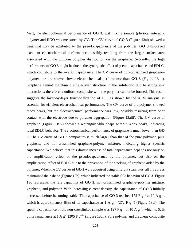
109
Next, the electrochemical performance of GO 3, just mixing sample (physical interact),
polymer and RGO was measured by CV. The CV curve of GO 3 (Figure 13ai) showed a
peak that may be attributed to the pseudocapacitance of the polymer. GO 3 displayed
excellent electrochemical performance, possibly resulting from the larger surface area
associated with the uniform polymer distribution on the graphene. Secondly, the high
performance of GO 3 might be due to the synergistic effect of pseudocapacitance and EDLC,
which contribute to the overall capacitance. The CV curve of non-crosslinked graphene–
polymer mixture showed lower electrochemical performance than GO 3 (Figure 13aii).
Graphene cannot maintain a single-layer structure in the solid-state due to strong π–π
interactions; therefore, a uniform composite with the polymer cannot be formed. This result
suggests the layer-by-layer functionalization of GO, as shown by the AFM analysis, is
essential for efficient electrochemical performance. The CV curve of the polymer showed
redox peaks, but the electrochemical performance was low, possibly resulting from poor
contact with the electrode due to polymer aggregation (Figure 13aiii). The CV curve of
graphene (Figure 13aiv) showed a rectangular-like shape without redox peaks, indicating
ideal EDLC behavior. The electrochemical performance of graphene is much lower than GO
3. The CV curve of GO 3 composites is much larger than that of the pure polymer, pure
graphene, and non-crosslinked graphene-polymer mixture, indicating higher specific
capacitance. We believe that this drastic increase of total capacitance depends not only on
the amplification effect of the pseudocapacitance by the polymer, but also on the
amplification effect of EDLC due to the prevention of the stacking of graphene aided by the
polymer. When the CV curves of GO 3 were acquired using different scan rates, all the curves
maintained their shape (Figure 13b), which indicated the stable SCs behavior of GO 3. Figure
13c represents the rate capability of GO 3, non-crosslinked graphene–polymer mixture,
graphene, and polymer. With increasing current density, the capacitance of GO 3 initially
decreased before becoming stable. The capacitance of GO 3 reached 172 F g1 at 10 A g1,
which is approximately 63% of its capacitance at 1 A g1 (272 F g1) (Figure 13ci). The
specific capacitance of the non-crosslinked sample was 127 F g1 at 10 A g1, which is 62%
of its capacitance at 1 A g1 (205 F g1) (Figure 13cii). Pure polymer and graphene composite

110
electrodes can only deliver a specific capacitance of 30 F g-1 and 40 F g-1, respectively, at a
current density of 1 A g -1, which decreased with increasing current density (Figure 13c (iii
and iv)). However, GO 3 demonstrated high capacitance due to the combined effect of
polymer (pseudocapacitance) and isolated graphene (EDLC), which allows fast transport of
electrolyte ion. The capacitances of all samples were calculated after five cycles.
Measurements of the cycling stability of GO 3 during repeated charge/discharge cycles
(Figure 13di) showed that its specific capacitance remained approximately 98% of its initial
capacitance after 1000 cycles with a constant current density of 10 A g1. Thus, GO 3 showed
good cycling stability in comparison with previous reports (Table 4). This illustrates that GO
3 possesses good stability, a long lifetime, and a high degree of reversibility during repetitive
charge/discharge cycling. In comparison, the non-crosslinked graphene–polymer mixture
displayed a lower capacitance that continuously decreased during several hundred cycles
(Figure 13dii), its capacitance retention being 63% after 1000 cycles. The high capacitance
and good cycling stability of GO 3 can be attributed to the strong covalent connection
between polymer and graphene and its uniform distribution on the graphene surface, allowing
fast transport of electrolyte ions

111
Figure 13: Electrochemical evaluation of a three-electrode system using a scan rate of 50
mV s1. (a) Cyclic voltammograms of (i) GO 3, (ii) just mixing, (iii) polymer, and (iv)
graphene. (b) Cyclic voltammograms of GO 3 at different scan rates. (c) Specific capacitance
of (i) GO 3, (ii) just mixing (non-crossed linked polymer-graphene), (iii) graphene, and (iv)
polymer as a function of current density. (d) Cycling stability of (i) GO 3, and (ii) just mixing
sample using a current density of 10 A g1

112
Table 4: Comparison of SCs performance in three-electrode systems
To comprehensively understand the capacitive response of GO 3, an electrochemical
impedance test was conducted (Figure 14a). The nearly vertical arm of the AC impedance in
the low-frequency region indicates an excellent capacitive behavior, representative of fast
ion diffusion and adsorption in or on the electrode material. The low resistance and fast ion
diffusion can be attributed to the uniform distribution of polymer on graphene connected by
covalent bond through cross-linker, which renders GO 3 promising as a SCs electrode. Figure
14b indicates the galvanostatic charge/discharge tests at a current density of 0.5, 1, 2, 5, and
10 A g-1. The nonlinear charge/discharge curves indicate the pseudocapacitive behavior of
the polymer in GO 3
Material Cycle
number
Capacity
retention
Measurement
conditions References
PANI-G 1500 90% 10 A g-1 [35]
PANI-G 1000 91% 2 A g-1 [36]
PANI-G 1500 80% 0.5 A g-1 [37]
PANI-G 200 96% 3 A g-1 [38]
PANI-G 1000 85% 0.5 A g-1 [39]
Ppy-G 1000 92% 1 A g-1 [40]
Ppy-G 200 93% 5 A g-1 [41]
Ppy-G 1500 71% 50 mV s-1 [42]
PEDOT-G 1000 88% 0.3 A g-1 [43]
PEDOT-G 2000 87% 0.5 A g-1 [44]
Ppy-G 500 90% 100 mVs-1 [45]
Ppy-G 1000 91% 1 A g-1 [46]
GO 3 1000 98% 10 A g-1 This work
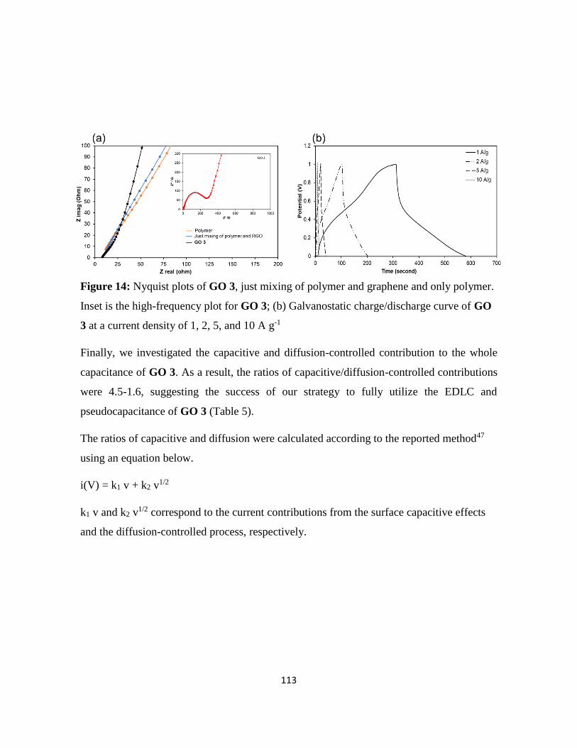
113
Figure 14: Nyquist plots of GO 3, just mixing of polymer and graphene and only polymer.
Inset is the high-frequency plot for GO 3; (b) Galvanostatic charge/discharge curve of GO
3 at a current density of 1, 2, 5, and 10 A g-1
Finally, we investigated the capacitive and diffusion-controlled contribution to the whole
capacitance of GO 3. As a result, the ratios of capacitive/diffusion-controlled contributions
were 4.5-1.6, suggesting the success of our strategy to fully utilize the EDLC and
pseudocapacitance of GO 3 (Table 5).
The ratios of capacitive and diffusion were calculated according to the reported method47
using an equation below.
i(V) = k1 v + k2 v1/2
k1 v and k2 v1/2 correspond to the current contributions from the surface capacitive effects
and the diffusion-controlled process, respectively.

114
Table 5: Calculation of Capacitive and diffusion-controlled contribution for GO 3 at 100
mV/sec
4.3. Conclusion
GO was functionalized with a polymer using simple mixing and heating, without the
addition of a catalyst, acid, or oxidant. The graphene–polymer composite GO 3 was prepared
using a sequential three-step reaction. Structural analyses showed that the polymer and the
graphene were cross-linked by a strong covalent bond. Polymer particles are uniformly
wrapped within or on the surface of graphene. The electrical properties of the composite were
evaluated to determine its suitability as an electrode material for a SCs. GO 3 demonstrated
a high capacitance (272 F g-1 for GO 3 vs. 205 F g-1 for the non-crosslinked graphene–
polymer mixture at 1 A g-1) and good cycling stability (98% @ 1000 cycles for GO 3 vs.
63% for the non-crosslinked graphene–polymer mixture at 10 A g-1). The superior
electrochemical performance of GO 3 is proposed due to the synergistic interaction of the
polymer and graphene, allowing for fast electron transfer. This method of functionalization
can be used for the future preparation of another graphene–polymer-based composites.
Specific potential Capacitive charge
storage
Diffusion charge
storage
0.3 V 71.6% 29.4%
0.4 V 62.3% 37.7%
0.5 V 64.3% 35.7%
0.6 V 82.4% 17.6%

115
4.4. Experimental section
4.4.1. Materials
Natural graphite fakes (99.8%) were obtained from Alfa Aesar. p-Phenylenediamine,
m-phenylenediamine, and 1,3-diaminopropane were obtained from Tokyo Chemical Industry
Co., Ltd. Potassium permanganate (KMnO4), sulfuric acid (H2SO4, 96%), thionyl chloride
(SOCl2), dimethylformamide (DMF), and ethanol were obtained from FUJIFILM Wako Pure
Chemical Corporation and used as received
4.4.2. Synthesis of GO
Natural graphite (100 g) was dispersed into concentrated H2SO4 (2.5 L). After
cooling the mixture in an ice bath, KMnO4 (300 g) was added while the reaction mixture was
kept below 55 °C. The mixture was stirred at 35 °C for 2 h to complete the oxidation. Next,
deionized water (2.5 L) was added slowly, and the temperature was kept below 50 °C with
continuous stirring, followed by the addition of H2O2 (30% aq., 250 mL) into the mixture.
Finally, the brown crude graphite oxide was purified by performing 10 times centrifugation,
and GO was prepared. The concentration of GO was measured by drying the GO dispersion
under vacuum at 50 °C overnight.
4.4.3. Preparation of N,N-bissulphinyl-m-benzenediamine (m-monomer)
m-Phenylenediamine (0.5 g) was taken in a 250 mL round-bottomed flask fitted with
a dropping funnel containing thermometer. The flask was kept in an ice-bath, and SOCl2 (1
mL) was added dropwise to m-phenylenediamine such that the reaction temperature was kept
below 0 °C. The flask was taken out from the ice bath and allowed to attain room temperature.
Then, the reaction mixture was refluxed for 8 h at 80 °C. The reaction mixture was filtered,
washed with benzene, and dried under vacuum.25
4.4.4. Synthesis of GO 1
In a typical procedure, 1,3-diaminopropane (0.5 mL) was added dropwise to the
suspension of GO (250 mg L-1, 400 mL) under vigorous stirring in a flask. The resulting
mixture was allowed to stir for 24 h at room temperature, then filtered and thoroughly washed
with ethanol and water several times. The obtained solid was freeze-dried for two days.
116
4.4.5. Synthesis of GO 2
In a typical procedure, the dispersion of GO 1 (140 mg) was prepared in DMF (50
mL). Then m-monomer (140 mg) was added to the GO 1 dispersion, and the mixture was
sonicated for 1 h. The mixture solution was refluxed at 160 °C for 24 h in an oil bath. After
completion of the reaction, the mixture solution was filtered, and the solid product was
washed with DMF and water several times. The product was then dried under vacuum for
two days.
4.4.6. Synthesis of GO 3
In a typical procedure, m-monomer (140 mg) was added into a dispersion of GO 1
(140 mg) in DMF (50 mL) and sonicated for 1 h. Then the reaction mixture was refluxed at
160 °C for 24 h in an oil bath to obtain GO 2. To this mixture, p-phenylenediamine (140 mg)
was added and refluxed at 180 °C for another 36 h. After completion of the reaction, the
reaction mixture was filtered, and the solid product was washed with DMF and water several
times. The final product was then dried under vacuum for two days to obtained GO 3.
4.4.7. Structural characterization
The thermogravimetry analysis (TGA, RIGAKU TG 8121) was measured at a
heating rate of 10 °C min-1 from room temperature to 900 °C under a nitrogen atmosphere.
FT-IR (SHIMADZU IR Tracer-100) were recorded in the range of 500-4000 cm-1. The
samples for FT-IR analysis were dried and mixed with KBr, and then pressed into 1.3 mm-
diameter pellets. The morphologies of the composite were characterized using SEM
(HITACHI S-5200) and AFM (SHIMADZU SPM-9700HT). Images were obtained through
the deposition of the dispersions on oxidized Si wafer in air at 800 °C or freshly cleaved mica
substrates by a drop-casting method. The cleaved mica was treated with UV ozone before
coated with the samples. The crystalline structure of samples was characterized by X-ray
diffraction (XRD, PANalytical Aeris) in the 2θ range of 5–40°. The operating tube current
and voltage were 30 mA and 40 kV, respectively. The elemental analysis was conducted
using XPS (JEOL JPS-9030) with a pass energy of 20 eV. EDS was performed using JSM-
IT 100 LA.

117
4.4.8. Electrochemical characterization
All electrochemical measurements were carried out with an electrochemical working
station (Solartron SI1287) at room temperature in an open three-electrode cell system. The
modified glassy carbon electrode ( = 3 mm) was used as the working electrode. A platinum
wire and Ag/AgCl were used as a counter electrode and a reference electrode, respectively.
Electrode material (20 mg) in NMP (1 mL) was sonicated to make uniform dispersion. 2 μL
of the dispersion was taken up using a pipet gun, dropped onto the glassy carbon electrode
( = 3 mm), and dried at 50 °C for 1 h under vacuum, then it was used as a working electrode.
The electrochemical performance was measured in a potential range of 0-1 V, with a scan
rate of 50 mVs-1. All electrochemical experiments were performed in 0.5 M H2SO4 aqueous
electrolyte. The electrochemical impedance test was conducted at a frequency range of 100
kHz to 0.01 Hz at 0.4 V with an AC perturbation of 5 mV. The specific capacitance of the
SCs (C (F g-1)) was calculated from the discharge curve according to the following formula:
C = I × Δt
m × ΔV
where I is the constant current in discharging, m is the mass of active material on working
electrode, Δt is the discharge time, and ΔV is the voltage change during discharge.

118
4.5. References
1. Y. Wang, Z. Shi, Y. Huang, Y. Ma, C. Wang, M. Chen, Y, J. Phys. Chem. C., 2009,
113, 13103-13107.
2. C. Liu, Z. Yu, D. Neff, A. Zhamu, B. Z. Jang, Nano Lett., 2010, 10, 4863-4868.
3. K. Zhang, L. L. Zhang, X. S. Zhao, J. Wu, Chem. Mater., 2010, 22, 1392-1401.
4. H. Yang, S. Kannappan, A. Pandian, J.-H. Jang, Y. Lee, W. Lu, Nanotechnol., 2017,
28, 445401.
5. F. Zhang, T. Zhang, X. Yang, L. Zhang, K. Leng, Y. Huang, Y. Chen, Energy Environ.
Sci., 2013, 6, 1623-1632.
6. D. Dutta, J. Y. Jiang, A. Jamaluddin, S. M. He, Y. H. Hung, F. Chen, J. K. Chang, C.
Y. Su, ACS Appl. Mater. Int., 2019, 11, 36560-36570.
7. A. Khosrozadeh, G. Singh, Q. Wang, G. Luo, M. Xing, J. Mater. Chem. A., 2018, 6,
21064-21077.
8. S. Ahmed, A. Ahmed, M. Rafat, J. Saudi Chem. Soc., 2018, 22, 993-1002.
9. W. Ma, S. Chen, S. Yang, M. Zhu, RSC Adv., 2016, 6, 50112-50118.
10. T. Nguyen, M. de F. Montemor, Adv. Sci., 2019, 6, 1801797.
11. G. A. Snook, P. Kao, A. S. Best, J. Power Sources, 2011, 196, 1-12.
12. S. Drieschner, M. Weber, J. Wohlketzetter, J. Vieten, E. Makrygiannis, B. M.
Blaschke, V. Morandi, L. Colombo, F. Bonaccorso, J. A. Garrido, 2D Mater., 2016, 3,
045013.
13. A. Klechikov, G. Mercier, T. Sharifi, I. A. Baburin, G. Seifert, A. V. Talyzin, Chem.
Commun. 2015, 51, 15280-15283.
14. Y. Qian, I. M. Ismail, A. Stein, Carbon 2014, 68, 221-231.
15. H. Murata, Y. Nakajima, N. Saitoh, N. Yoshizawa, T. Suemasu, K. Toko, Sci. Rep.,
2019, 9, 4068.
16. M. A. Worsley, P. J. Pauzauskie, T. Y. Olson, J. Biener, J. H. Satcher, T. F. Baumann,
J. Am. Chem. Soc., 2010, 132, 14067-14069.
17. D. G. Papageorgiou, I. A. Kinloch, R. J. Young, Prog. Mater. Sci., 2017, 90, 75-
127.

119
18. L. Liu, J. Zhang, J. Zhao, F. Liu, Nanoscale 2012, 4, 5910-5916.
19. S. Jo, Y. H. Park, S. G. Ha, S. M. Kim, C. Song, S. Y. Park, I. In, Synth. Met., 2015,
209, 60-67.
20. Z. Liu, H. Zhou, Z. Huang, W. Wang, F. Zeng, Y. Kuang, J. Mater. Chem. A., 2013,
1, 3454-3462.
21. Z. Gao, F. Wang, J. Chang, D. Wu, X. Wang, X. Wang, F. Xu, S. Gao, K. Jiang,
Electrochim. Acta, 2014, 133, 325-334.
22. N. A. Kumar, H. J. Choi, Y. R. Shin, D. W. Chang, L. Dai, J.-B. Baek, ACS Nano
2012, 6, 1715-1723.
23. L. Jianhua, A. Junwei, Z. Yecheng, M. Yuxiao, L. Mengliu, Y. Mei, L. Songmei,
ACS Appl. Mater. Interfaces, 2012, 4, 2870-2877.
24. L. Lai, H. Yang, L. Wang, B. K. Teh, J. Zhong, H. Chou, L. Chen, W. Chen, Z. Shen,
R.S. Ruoff, J. Lin, ACS Nano 2012, 6, 5941-5951.
25. N. A. El-Ghamaz, T. S. Ahmed, D. A. Salama, Eur. Polym. J. 2017, 93, 8-20.
26. I. A. Vacchi, C. Spinato, J. Raya, A. Bianco, C. Menard-Moyon, Nanoscale, 2016,
8, 13714-13721.
27. B. Qian, C. Liu, J. Xu, Q. Sun, H. Yang, W. Liu, L. Zhang, T. Minari, X. Liu, J.
Chen, J. Phys. D: Appl. Phys. 2019, 52, 295502.
28. Z. Yang, Y. Dai, S. Wang, H. Cheng, J. Yu, RSC Adv. 2015, 5, 78017-78025.
29. D. Mhamane, S. Unni, A. Suryawanshi, O. Game, C. Rode, B. Hannoyer, S.
Kurungot, S. Ogale, activity, J. Mater. Chem. 2012, 22, 11140-11145.
30. C. C. Caliman, A. F. Mesquita, D. F. Cipriano, J. C. C. Freitas, A. a. C. Cotta, W. a.
A. Macedo, A. O. Porto, RSC Adv. 2018, 8, 6136-6145.
31. J. Hu, B. He, J. Lu, L. Hong, J. Yuan, J. Song, L. Niu, Int. J. Electrochem. 2012, 7,
10094-10107.
32. Y. Gong, D. Li, Q. Fu, C. Pan, Prog. Nat. Sci. Mater. Int. 2015, 25, 379-385.
33. H. Zare-Zardini, A. Taheri-Kafrani, A. Amiri, A. K. Bordbar, Sci. Rep. 2018, 8, 586.
34. J. L. Yan, G. J. Chen, C. A. O. Jun, Y. Wei, B. H. Xie, M. B. Yang, New Carbon
Mater. 2012, 27, 370-376.

120
35. Z. Liu, H. Zhou, Z. Huang, W. Wang, F. Zeng, Y. Kuang, J. Mater. Chem. A., 2013,
1, 3454–3462.
36. L. Wang, Y. Ye, X. Lu, Z. Wen, Z. Li, H. Hou, Y. Song, Sci. Rep., 2013, 3, 3568.
37. U. Male, J. K. R. Modigunta, D. S. Huh, Polymer, 2017, 110, 242–249.
38. L. Jianhua, A. Junwei, Z. Yecheng, M. Yuxiao, L. Mengliu, Y. Mei, L. Songmei,
ACS Appl. Mater. Inter., 2012, 4, 2870–2876.
39. H. Qiu, X. Han, F. Qiu, J. Yang, Appl. Surf. Sci., 2016, 376, 261–268.
40. Y. Liu, Y. Zhang, G. Ma, Z. Wang, K. Liu, H. Liu, Electrochim. Acta., 2013, 88,
519–525.
41. S. Jo, Y. H. Park, S. G. Ha, S. M. Kim, C. Song, S. Y. Park, I. In, Synthetic Metals,
2015, 209, 60–67.
42. X. Zuo, Y. Zhang, L. Si, B. Zhou, B. Zhao, L. Zhu, X. Jiang, J. Alloys Compd.,
2016, 688, 140–148.
43. J. Zhang, X. S. Zhao, J. Phys. Chem. C., 2012, 116, 5420–5426,
44. J. Wen, Y. Jiang, Y. Yang, S. Li, J. Mater. Sci. Mater. Electron., 2014, 25, 1063–
1071.
45. S. Bose, N. H. Kim, T. Kuila, K. Lau, J. H. Lee, Nanotechnol., 2011, 22, 295202,
46. Y. Song, J. L. Xu, X. X. Liu, J. Power Sources, 2014, 249, 48–58.
47. J. Wang, J. Polleux, J. Lim, B. J. Dunn, J. Phys. Chem. C. 2007, 111, 14925-14931.

121
Chapter 5
Covalent double functionalization enables multi-function and
enhanced performance

122
Abstract ……………………………………………………………………………. 123
5.1. Introduction …………………………………………………………………… 123
5.2. Result and discussion ………………………………………………………… 124
5.2.1. Functionalization of GO for proton conductivity ………………………….. 128
5.2.2. Functionalization of GO for SCs application ……………………………… 135
5.2.3. Electrochemical performance as a SCs …………………………………… 139
5.3. Conclusion ………………………………………………………………….... 143
5.4. Experimental section ………………………………………………………... 143
5.4.1. Chemicals and materials …………………………………………………... 143
5.4.2. Synthesis of 2-amino-1,4-naphthoquinone ……………………………….. 143
5.4.3. Synthesis of GO …………………………………………………………... 144
5.4.4. General procedure for the synthesis of GO 1 and GO 5 ………………….. 144
5.4.5. General procedure for the synthesis of GO 2 (a-c), GO 4, GO 6,
GO 7 and GO 9 …………………………………………………………... 144
5.4.6. Synthesis of GO 3 and GO 8 ……………………………………………... 144
5.4.7. Instruments and measurements …………………………………………... 145
5.5. References ………………………………………………………………….. 146

123
Abstract: Covalent double functionalization of GO is an effective approach to tune the
properties of graphene-like materials. The first step is the ring-opening reaction of epoxides
by amines, and the second step is the nucleophilic addition reaction of hydroxyl groups to
α,β-unsaturated carbonyl compounds. The benefits of doubly functionalized GO are to
possess multifunctions and many functions, confirmed by measuring proton conductivity and
redox performance. The proton conductivity can be granted by introducing sulfonic acid
functional groups on GO, while the redox property can be improved by introducing quinone
molecules. The current study evidence that double functionalization efficiently works in the
design of multifunctional GO for specific applications, such as electrolyte membranes for
fuel cells and electrode materials for SCs.
5.1. Introduction
GO and its derivatives have attracted considerable interest from the scientific and
industrial communities due to their excellent electrical,1 mechanical properties,2 and potential
for large-scale production. Therefore, their applications have been actively investigated for
transistors,3 transparent electrodes,4 sensors,5–7 polymer composites,8–10 ultrastrong
materials,11 electrocatalysts,12–14 and energy storage devices.15,16 GO has reactive oxygenated
functional groups such as epoxy and hydroxyl groups at the basal plane and carboxylic acid
and carbonyl groups at the edge.17 Basal plane functionalization is more desirable to
introduce as many functions as possible; therefore, nucleophilic addition to epoxide18 and
that of hydroxyl groups19 have been investigated. Utilizing the epoxide and hydroxyl of GO
in a stepwise manner is the concept of covalent double functionalization.20 The covalent
double functionalization allows the attachment of target molecules through different
reactions. In addition, the bonds between GO and the molecules are more stable than
noncovalent conjugates.21–23
Previous researches evidenced that double functionalization of GO can introduce various
functional groups, but targeted applications have not been shown. In this work, we focused
on the covalent double functionalization of GO to tune the electrochemical properties, and

124
applied for electrode materials. To this end, two different organic molecules with specific
functions were introduced on GO using a stepwise covalent double functionalization; the first
step consists of the ring-opening reaction of epoxide groups of GO with an amino compound,
and the second step is the nucleophilic addition of hydroxyl groups on GO to an α,β-
unsaturated carbonyl compounds. The advantageous feature of the strategy was confirmed
by measuring proton conductivity and capacitance for SCs.
5.2. Results and discussion
Initially, GO was functionalized by simple organic molecules to optimize the double
functionalization conditions. The first step consists of the reaction of propylamine with the
epoxide groups of GO,24–26 allowing to introduce the first functionality and to generate more
hydroxyl groups, which subsequently reacted with α,β-unsaturated carbonyl compounds such
as methylvinyl ketone (a), 1,4-benzoquinone (b) and 1,4-naphthoquinone (c) (Figure 1).20
The prepared materials were characterized by XPS, FT-IR, and CV.
Figure 1: Synthesis of GO1, GO 2a, GO 2b, and GO 2c: for simplicity only one hydroxyl
group derivatized in GO 2 (a-c)

125
The wide scan XPS spectra of propyl amine functionalized GO (GO 1), and GO 2a-2c
contains carbon, oxygen and nitrogen (Figure 2 i-iv). The presence of nitrogen atom in the
spectra of GO 1 confirmed the grafting of propylamine on the surface. The detail percentage
of each element is listed in Table 1. The high-resolution XPS analysis of N 1s peak in GO 1,
and GO 2a-2c appeared at 399.5 eV, attributed to the new N−C bond, thus confirming the
epoxide opening (Figure 3 a-d).27
Figure 2: Wide scan XPS spectra of (i) GO 1, (ii) GO 2a, (iii) GO 2b, and (iv) GO 2c
Table 1: Quantitative comparison of detected element from the wide scan XPS spectra of
GO 1, GO 2a, GO 2b, and GO 2c
Sample Element at.%
C O N
GO 1 74.4 24.3 1.1
GO 2a 70.7 27.1 1.3
GO 2b 70.7 27.9 1.2
GO 2c 70.5 28.1 1.2
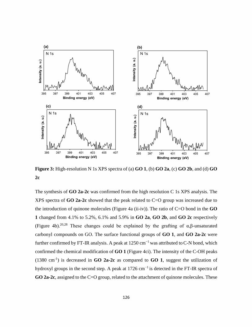
126
Figure 3: High-resolution N 1s XPS spectra of (a) GO 1, (b) GO 2a, (c) GO 2b, and (d) GO
2c
The synthesis of GO 2a-2c was confirmed from the high resolution C 1s XPS analysis. The
XPS spectra of GO 2a-2c showed that the peak related to C=O group was increased due to
the introduction of quinone molecules (Figure 4a (ii-iv)). The ratio of C=O bond in the GO
1 changed from 4.1% to 5.2%, 6.1% and 5.9% in GO 2a, GO 2b, and GO 2c respectively
(Figure 4b).20,28 These changes could be explained by the grafting of α,β-unsaturated
carbonyl compounds on GO. The surface functional groups of GO 1, and GO 2a-2c were
further confirmed by FT-IR analysis. A peak at 1250 cm−1 was attributed to C-N bond, which
confirmed the chemical modification of GO 1 (Figure 4ci). The intensity of the C-OH peaks
(1380 cm-1) is decreased in GO 2a-2c as compared to GO 1, suggest the utilization of
hydroxyl groups in the second step. A peak at 1726 cm−1 is detected in the FT-IR spectra of
GO 2a-2c, assigned to the C=O group, related to the attachment of quinone molecules. These
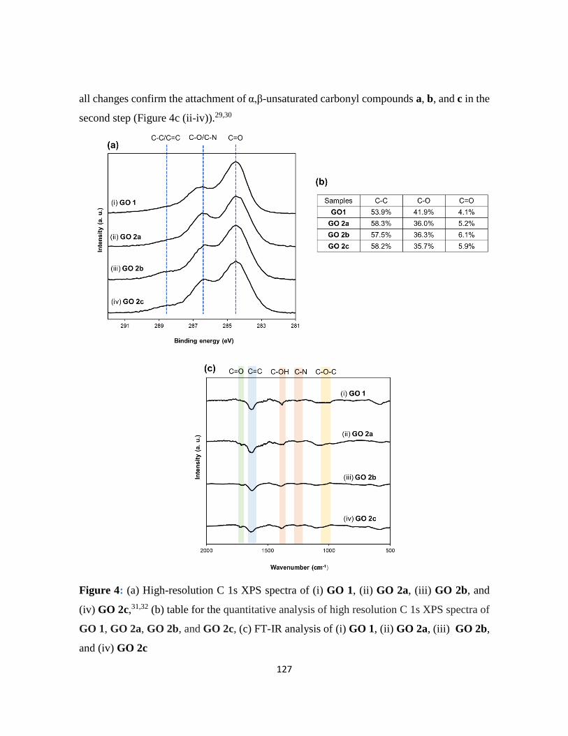
127
all changes confirm the attachment of α,β-unsaturated carbonyl compounds a, b, and c in the
second step (Figure 4c (ii-iv)).29,30
Figure 4: (a) High-resolution C 1s XPS spectra of (i) GO 1, (ii) GO 2a, (iii) GO 2b, and
(iv) GO 2c,31,32 (b) table for the quantitative analysis of high resolution C 1s XPS spectra of
GO 1, GO 2a, GO 2b, and GO 2c, (c) FT-IR analysis of (i) GO 1, (ii) GO 2a, (iii) GO 2b,
and (iv) GO 2c

128
To further confirm the double functionalization by Michael reaction, CV measurement was
performed (Figure 5). CV is sensitive to the redox-active molecules.33 The CV curve of GO
2a showed no redox peaks, while the CV curve of the GO 2b, and GO 2c showed the
expected redox peaks. The redox peaks for GO 2b, and GO 2c appeared at different
potentials. The redox potential of redox-active molecule changes with change in the
molecular structure.
Figure 5: CV study of GO 2a, GO 2b, and GO 2c
5.2.1. Functionalization of GO for proton conductivity
Next, the role of double functionalized GO was investigated in the proton
conductivity. Thus, the proton conductivity of the GO was improved by tuning the surface
functional groups. For this purpose, sulfanilic acid was grafted on GO through epoxide group
(GO 3), followed by the attachment of 1,4-benzoquinone (BQ) molecules (GO 4). Sulfanilic
acid act as proton conducting material which are previously reported.34 For comparison,
aniline was functionalized on GO (GO 5), followed by the attachment of BQ (GO 6) (Figure
6).

129
Figure 6: Synthesis of GO 3, GO 4, GO 5, and GO 6: (for simplicity only one hydroxyl
group derivatized in GO 4 and GO 6)
The synthesis of the materials was confirmed by XPS analysis. In the first step GO 3 and
GO 5 was prepared through ring opening rection of epoxides. The wide scan XPS spectra of
GO 3 showed the presence of carbon, oxygen, nitrogen and sulfur, while the XPS spectra of
GO 5 contains carbon, oxygen and nitrogen (Figure 7). The presence of sulfur and nitrogen
in GO 3, and GO 5 confirmed the first step. The detail percentage of each element is given
in Table 2. The high-resolution S 2p spectra of GO 3, and GO 4 was appeared at 168.0 eV,
attributed to the sulfonic group, thus confirm the presence of sulfanilic acid (Figure 8a and
8b). The high-resolution N 1s peak of GO 3, and GO 5 was appeared at 399.5 eV, attributed
to the new N−C bond, thus confirming the epoxide opening (Figure 8c and 8e). The same
peaks (high-resolution N 1s) were also observed in the XPS spectra of GO 4, and GO 6
(Figure 8d and 8f).

130
Figure 7: Wide scan XPS spectra of (i) GO 3, (ii) GO 4, (iii) GO 5, and (iv) GO 6
Table 2: Quantitative comparison of detected element from the wide scan XPS spectra of
GO 3, GO 4, GO 5, and GO 6
Sample at.% (Element)
C O N S
GO 3 71.3 25.5 1.1 1.0
GO 4 71.9 25.3 1.2 1.0
GO 5 73.6 25.0 1.2 --
GO 6 73.8 24.2 1.2 --

131
Figure 8: High-resolution S 2p XPS spectra of (a) GO 3 and (b) GO 4, N 1s XPS spectra
of (c) GO 3, (d) GO 4, (e) GO 5, and (f) GO 6
The second step was confirmed by the high-resolution C1s XPS spectra (Figure 9). The
number of C=O group was increased in GO 4, and GO 6, due to the introduction of quinone
molecules. The ratio of C=O bond was 4.5%, and 5.1% in GO 3, and GO 5 respectively. The
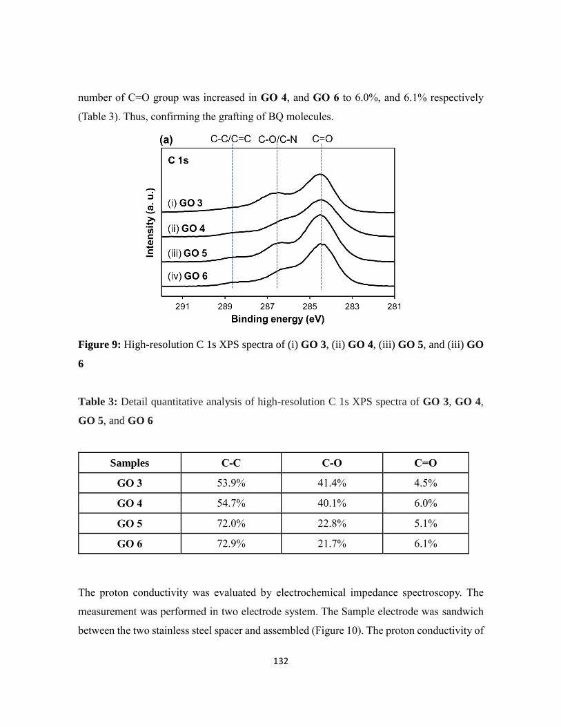
132
number of C=O group was increased in GO 4, and GO 6 to 6.0%, and 6.1% respectively
(Table 3). Thus, confirming the grafting of BQ molecules.
Figure 9: High-resolution C 1s XPS spectra of (i) GO 3, (ii) GO 4, (iii) GO 5, and (iii) GO
6
Table 3: Detail quantitative analysis of high-resolution C 1s XPS spectra of GO 3, GO 4,
GO 5, and GO 6
Samples C-C C-O C=O
GO 3 53.9% 41.4% 4.5%
GO 4 54.7% 40.1% 6.0%
GO 5 72.0% 22.8% 5.1%
GO 6 72.9% 21.7% 6.1%
The proton conductivity was evaluated by electrochemical impedance spectroscopy. The
measurement was performed in two electrode system. The Sample electrode was sandwich
between the two stainless steel spacer and assembled (Figure 10). The proton conductivity of
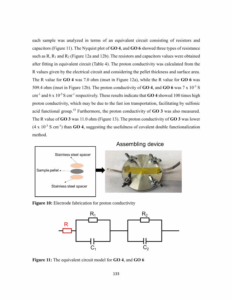
133
each sample was analyzed in terms of an equivalent circuit consisting of resistors and
capacitors (Figure 11). The Nyquist plot of GO 4, and GO 6 showed three types of resistance
such as R, R1 and R2 (Figure 12a and 12b). The resistors and capacitors values were obtained
after fitting in equivalent circuit (Table 4). The proton conductivity was calculated from the
R values given by the electrical circuit and considering the pellet thickness and surface area.
The R value for GO 4 was 7.0 ohm (inset in Figure 12a), while the R value for GO 6 was
509.4 ohm (inset in Figure 12b). The proton conductivity of GO 4, and GO 6 was 7 x 10⁻³ S
cm-1 and 6 x 10⁻⁵ S cm-1 respectively. These results indicate that GO 4 showed 100 times high
proton conductivity, which may be due to the fast ion transportation, facilitating by sulfonic
acid functional group.35 Furthermore, the proton conductivity of GO 3 was also measured.
The R value of GO 3 was 11.0 ohm (Figure 13). The proton conductivity of GO 3 was lower
(4 x 10⁻³ S cm-1) than GO 4, suggesting the usefulness of covalent double functionalization
method.
Figure 10: Electrode fabrication for proton conductivity
Figure 11: The equivalent circuit model for GO 4, and GO 6
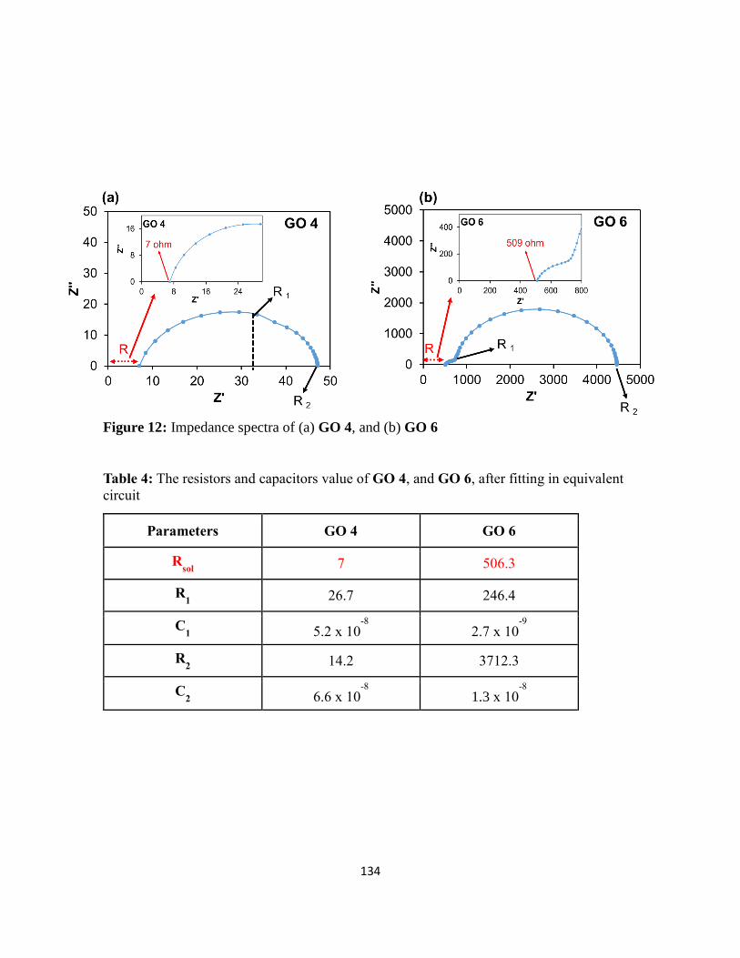
134
Figure 12: Impedance spectra of (a) GO 4, and (b) GO 6
Table 4: The resistors and capacitors value of GO 4, and GO 6, after fitting in equivalent
circuit
Parameters GO 4 GO 6
Rsol
7 506.3
R1 26.7 246.4
C1 5.2 x 10
-8
2.7 x 10⁻⁹
R2 14.2 3712.3
C2 6.6 x 10
-8
1.3 x 10⁻⁸
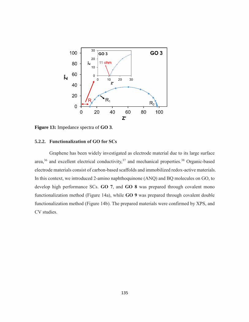
135
Figure 13: Impedance spectra of GO 3.
5.2.2. Functionalization of GO for SCs
Graphene has been widely investigated as electrode material due to its large surface
area,36 and excellent electrical conductivity,37 and mechanical properties.38 Organic-based
electrode materials consist of carbon-based scaffolds and immobilized redox-active materials.
In this context, we introduced 2-amino naphthoquinone (ANQ) and BQ molecules on GO, to
develop high performance SCs. GO 7, and GO 8 was prepared through covalent mono
functionalization method (Figure 14a), while GO 9 was prepared through covalent double
functionalization method (Figure 14b). The prepared materials were confirmed by XPS, and
CV studies.
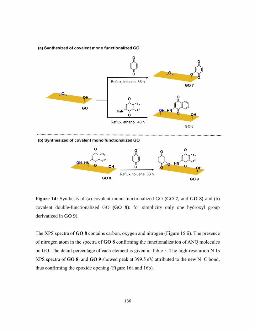
136
Figure 14: Synthesis of (a) covalent mono-functionalized GO (GO 7, and GO 8) and (b)
covalent double-functionalized GO (GO 9): for simplicity only one hydroxyl group
derivatized in GO 9).
The XPS spectra of GO 8 contains carbon, oxygen and nitrogen (Figure 15 ii). The presence
of nitrogen atom in the spectra of GO 8 confirming the functionalization of ANQ molecules
on GO. The detail percentage of each element is given in Table 5. The high-resolution N 1s
XPS spectra of GO 8, and GO 9 showed peak at 399.5 eV, attributed to the new N−C bond,
thus confirming the epoxide opening (Figure 16a and 16b).

137
Figure 15: Wide scan XPS spectra of (i) GO 7, (ii) GO 8, and (iii) GO 9
Table 5: Quantitative comparison of detected element from the wide scan XPS spectra of
GO 7, GO 8, and GO 9
Sample Element at.%
C O N
GO 7 73.3 26.7 --
GO 8 72.4 26.2 1.2
GO 9 71.6 26.8 1.5

138
Figure 16: High-resolution N 1s XPS spectra of (a) GO 8, and (b) GO 9
The high-resolution C 1s XPS spectra showed that GO 8 still contains large number of
hydroxyl groups (Figure 17aii). The spectra of GO 9 showed that the peak related to hydroxyl
group was decreased while the peak of C=O group was increased due to the introduction of
more quinone molecules (Figure 17aiii). The area of the C−C, C-OH and C=O peaks in the
detailed analysis of the C1s spectrum of GO 9 was changed from 43.9%, 50.9%, and 3.4%
to 44.6%, 47.3%, and 8.0 %, respectively, compared with GO 8 (Table 6). These changes
could be explained by the grafting of BQ molecules onto GO.

139
Figure 17: (a) High-resolution C 1s XPS spectra of (i) GO 7, (ii) GO 8, and (iii) GO 9
Table 6: Detail quantitative analysis of high-resolution C 1s XPS spectra of GO 7, GO 8,
and GO 9
5.2.3. Electrochemical performance as a SCs
The electrochemical behavior of GO 7, GO 8, and GO 9 were evaluated by CV
analysis. GO 7 showed an oxidation peak at 0.53 V and a reduction peak at 0.51 V (Figure
18ai), while GO 8 has an oxidation peak at 0.15 V and a reduction peak at 0.12 V (Figure
18aii). The redox peaks for GO 7, and GO 8 appeared at different potential, due to different
Samples C-C C-OH C=O
GO 7 50.3% 45.1% 4.4%
GO 8 43.9% 50.9% 3.4%
GO 9 44.6% 47.3% 8.0%
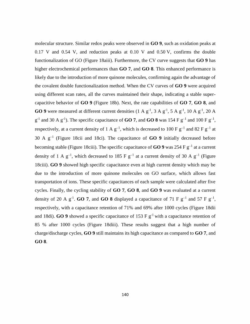
140
molecular structure. Similar redox peaks were observed in GO 9, such as oxidation peaks at
0.17 V and 0.54 V, and reduction peaks at 0.10 V and 0.50 V, confirms the double
functionalization of GO (Figure 18aiii). Furthermore, the CV curve suggests that GO 9 has
higher electrochemical performances than GO 7, and GO 8. This enhanced performance is
likely due to the introduction of more quinone molecules, confirming again the advantage of
the covalent double functionalization method. When the CV curves of GO 9 were acquired
using different scan rates, all the curves maintained their shape, indicating a stable super-
capacitive behavior of GO 9 (Figure 18b). Next, the rate capabilities of GO 7, GO 8, and
GO 9 were measured at different current densities (1 A g-1, 3 A g-1, 5 A g-1, 10 A g-1, 20 A
g-1 and 30 A g-1). The specific capacitance of GO 7, and GO 8 was 154 F g1 and 100 F g1,
respectively, at a current density of 1 A g1, which is decreased to 100 F g1 and 82 F g1 at
30 A g1 (Figure 18cii and 18ci). The capacitance of GO 9 initially decreased before
becoming stable (Figure 18ciii). The specific capacitance of GO 9 was 254 F g1 at a current
density of 1 A g1, which decreased to 185 F g1 at a current density of 30 A g1 (Figure
18ciii). GO 9 showed high specific capacitance even at high current density which may be
due to the introduction of more quinone molecules on GO surface, which allows fast
transportation of ions. These specific capacitances of each sample were calculated after five
cycles. Finally, the cycling stability of GO 7, GO 8, and GO 9 was evaluated at a current
density of 20 A g-1. GO 7, and GO 8 displayed a capacitance of 71 F g1 and 57 F g1,
respectively, with a capacitance retention of 71% and 69% after 1000 cycles (Figure 18dii
and 18di). GO 9 showed a specific capacitance of 153 F g-1 with a capacitance retention of
85 % after 1000 cycles (Figure 18diii). These results suggest that a high number of
charge/discharge cycles, GO 9 still maintains its high capacitance as compared to GO 7, and
GO 8.
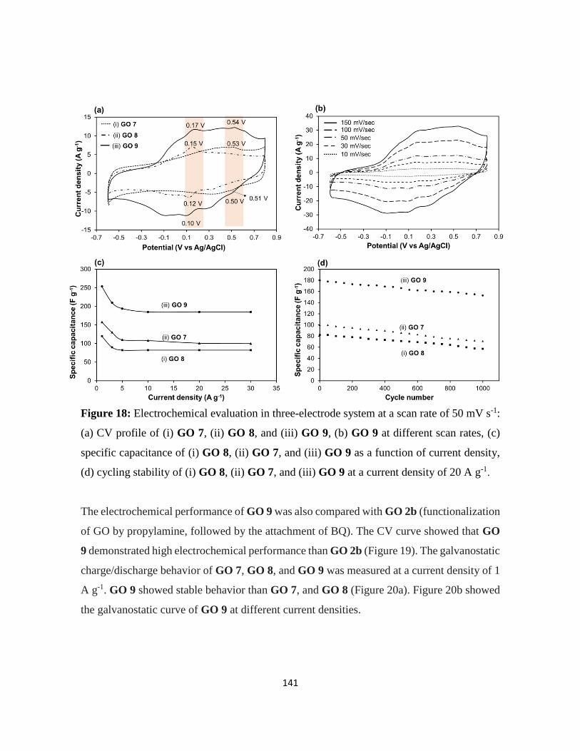
141
Figure 18: Electrochemical evaluation in three-electrode system at a scan rate of 50 mV s-1:
(a) CV profile of (i) GO 7, (ii) GO 8, and (iii) GO 9, (b) GO 9 at different scan rates, (c)
specific capacitance of (i) GO 8, (ii) GO 7, and (iii) GO 9 as a function of current density,
(d) cycling stability of (i) GO 8, (ii) GO 7, and (iii) GO 9 at a current density of 20 A g-1.
The electrochemical performance of GO 9 was also compared with GO 2b (functionalization
of GO by propylamine, followed by the attachment of BQ). The CV curve showed that GO
9 demonstrated high electrochemical performance than GO 2b (Figure 19). The galvanostatic
charge/discharge behavior of GO 7, GO 8, and GO 9 was measured at a current density of 1
A g-1. GO 9 showed stable behavior than GO 7, and GO 8 (Figure 20a). Figure 20b showed
the galvanostatic curve of GO 9 at different current densities.

142
Figure 19: Electrochemical evaluation in three-electrode system: CV profile of GO 2b, and
GO 9 at a scan rate of 50 mV s-1
Figure 20: (a) Galvanostatic charge discharge curve of (i) GO 7, (ii) GO 8, and (i) GO 9 at
a current density of 1 A g-1 (b) GO 9 at different current density

143
5.3. Conclusion
In summary, a series of organic molecules were introduced onto the surface of GO by
using a covalent double functionalization method. In first step, the aminated compounds were
reacted with the epoxide groups of GO. The monofunctionalized GO, containing more OH
groups compared to pristine GO, was then modified with α,β-unsaturated carbonyl
compounds. The prepared materials were applied as electrode materials for proton
conductivity and SCs. The proton conductivity of GO was improved by attaching sulfanilic
acid, followed by the introduction of BQ molecules. The SC performance was improved by
introducing two redox-active molecules onto GO through the same covalent double
functionalization approach. This strategy could be exploited further to prepare
multifunctional GO conjugates with potential applications in many fields.
5.4. Experimental section
5.4.1. Chemicals and materials
Natural graphite fakes (99.8%) were obtained from Alfa Aesar.1,4 benzoquinone,
methyl vinylketone, propylamine and aniline was obtained from Tokyo chemical industry
Co., Ltd. Toluene was obtained from Kanto chemical co. ink. Potassium permanganate
(KMnO4), sulfuric acid (H2SO4, 96%), ethanol, sodium azide, acetic acid, tetrahydrofuran,
1,4-naphthoquinone and sulfanilic acid were obtained from Wako Co., Ltd and used as
received.
5.4.2. Synthesis of 2-amino-1,4-naphthoquinone
A round-bottom flask equipped with a magnetic stir-bar was charged with 1,4-
naphthoquinone (2.37 g, 15 mmol, 1.0 equiv.) and H2O/THF (1/4, 50 mL). To the mixture, a
solution of sodium azide (2.93 g, 45 mmol, 3.0 equiv.) and acetic acid (3 mL) in distilled
water (8 mL) was added and stirred at room temperature. After 7 h, the reaction was
concentrated in vacuo and dissolved in ethyl acetate. The resulting solution was washed with
1 M NaOH, extracted with ethyl acetate, and washed with saturated NaCl. The organic layers
were dried over MgSO4 and the solvent was removed in vacuo. The crude residue was

144
purified by silica gel column chromatography (hexane/ethyl acetate = 1/2) to give 2.3 g (89%)
as a brown solid.39
5.4.3. Synthesis of GO
Graphite powder (100 g) was dispersed into concentrated H2SO4 (2.5 L). After
cooling the mixture in an ice bath, KMnO4 (300 g) was added and reaction mixture was kept
below 55 ◦C. The mixture was stirred at 35 °C for 2 h to complete the oxidation process. Next,
deionized water (5 L) was added slowly and temperature was kept below 50 °C with
continuous stirring, then followed by the addition of H2O2 (30% aq., 250 mL) into the mixture.
Finally, the brown crude graphite oxide was purified by performing 10 times centrifugation,
and GO is prepared. Concentration of GO was measured by drying the GO dispersion under
vacuum at 50 °C.
5.4.4. General procedure for the synthesis of GO 1, and GO 5
In a typical procedure, amine (1 mL) was added dropwise to the suspension of GO
(250 mg L−1, 400 mL) under vigorous stirring in a flask. The resulting mixture was allowed
to stir for 24 h at room temperature, then filtered and thoroughly washed with ethanol and
water several times. The obtained solid was freeze-dried for two days.
5.4.5. General procedure for the synthesis of GO 2 (a-c), GO 4, GO 6, GO 7, and GO
9
To a dispersion of GO (40 mg) in toluene (5 mL), a solution of α,β-unsaturated
carbonyl compounds (300 mg) in toluene (10 mL) was added. The mixture was refluxed for
36 h at 112 °C with constant stirring. After completion of reaction the mixture was filtered
and washed with water and toluene several times respectively. The sample was then dried
under vacuum for two days at 50 °C.
5.4.6. Synthesis of GO 3, and GO 8
In a typical procedure, amine (300 mg) was dissolved in 30 mL ethanol and then
added to GO aqueous dispersion (10 mL, 10 mg mL-1, 100 mg). The mixture was sonicated
for 1 h to get a homogeneous dispersion. The dispersion was refluxed for 48 h and purified
by centrifugation and washing (ethanol and then water, 3 times each). The product was finally
freeze dried for two days.

145
5.4.7. Instruments and measurements
The functional groups on the surface of GO were recorded by FT-IR (SHIMADZU
IR Tracer 100), Using KBr analysis. The elemental compositions were determined by XPS.
The XPS was carried out on a JPS-9030 with a pass energy of 20 eV.
The electrochemical behavior of prepared samples was measured using three electrode
system. In the three-electrode system, the platinum foil and Ag/AgCl electrode were used as
the counter electrode and reference electrode, respectively. The working electrode was
fabricated by mixing electrode material (4 mg) and carbon black (0.7 mg) in 0.4 mL Nafione
solution, which is sonicated for I h to make fine dispersion. Then 3 μL of above suspension
using a pipet gun was dropped onto the glassy carbon electrode (3 mm) and completely dried
at 50 °C for 1 h under vacuum. The electrochemical performance was measured in a potential
range of -0.6-0.8 V, with a scan rate of 50 mVs-1. All electrochemical experiments were
performed in 0.5 M H2SO4 aqueous electrolyte. The specific capacitance of the SCs (C (F/g))
was calculated from the discharge curve according to the following formula:
C = I X Δt
m X ΔV ……………………. 1
where I is the constant current in discharging, m is the mass of active material on working
electrode, Δt is the discharge time, and ΔV is the voltage change during discharge.
For proton conductivity the sample was pressed into 10 mm diameter pellets. The thickness
of the pellet for GO 4, and GO 6 was 0.414 mm 0.25 mm respectively. The Sample electrode
was sandwich between the two stainless steel spacer and assembled.40 The electrochemical
impedance test was conducted at a frequency range of 1000 kHz to 1 Hz at 0 V with an AC
perturbation of 10 mV. The proton conductivity was measured by following by equation:
σ = L
Z .A …………………. 2
where L is the thickness of the electrode, Z is impedance value and A is the electrode surface
area.

146
5.5. References
1. J.-H. Lee, S.-J. Park and J.-W. Choi, Nanomaterials, 2019, 9, 297.
2. D. G. Papageorgiou, I. A. Kinloch and R. J. Young, Prog. Mater. Sci., 2017, 90,
75–127.
3. B. Zhan, C. Li, J. Yang, G. Jenkins, W. Huang and X. Dong, Small, 2014, 10,
4042–4065.
4. S. Pang, Y. Hernandez, X. Feng and K. Müllen, Adv. Mater., 2011, 23, 2779–2795.
5. H. Huang, S. Su, N. Wu, H. Wan, S. Wan, H. Bi and L. Sun, Front Chem., 2019, 7,
399.
6. W. Yuan and G. Shi, J. Mater. Chem. A, 2013, 1, 10078–10091.
7. M. Hernaez, Sensors, 2020, 20, 3196.
8. T. Kuilla, S. Bhadra, D. Yao, N. H. Kim, S. Bose and J. H. Lee, Prog. Polym. Sci.,
2010, 35, 1350–1375.
9. C. Wang, Y. Yang, R. Li, D. Wu, Y. Qin and Y. Kong, Chem. Commun., 2020, 56,
4003–4006.
10. D. Majumdar, Innovative Energ. Res., 2016, 5, 1–9.
11. Z. Xu, H. Sun, X. Zhao and C. Gao, Adv. Mater., 2013, 25, 188–193.
12. V. Mazánek, J. Luxa, S. Matějková, J. Kučera, D. Sedmidubský, M. Pumera and Z.
Sofer, ACS Nano, 2019, 13, 1574–1582.
13. D. Higgins, P. Zamani, A. Yu and Z. Chen, Energy Environ. Sci., 2016, 9, 357–390.
14. D. Geng, N. Ding, T. S. A. Hor, Z. Liu, X. Sun and Y. Zong, J. Mater. Chem. A,
2015, 3, 1795–1810.
15. R. Khan, R. Nakagawa, B. Campeon and Y. Nishina, ACS Appl. Mater. Interfaces,
2020, 12, 12736–12742.
16. Z. J, Y. D, Y. Z, Y. Q and Z. H, Small, 2014, 10, 3480–3498.
17. D. R. Dreyer, S. Park, C. W. Bielawski and R. S. Ruoff, Chem. Soc. Rev., 2010, 39,
228–240.
18. B. Xue, J. Zhu, N. Liu and Y. Li, Catal Commun., 2015, 64, 105–109.

147
19. I. A. Vacchi, S. Guo, J. Raya, A. Bianco and C. Ménard-Moyon, Eur. J. Chem.,
2020, 26, 6591-6598.
20. S. Guo, Y. Nishina, A. Bianco and C. Ménard‐Moyon, Angew. Chem. Int. Ed.,
2020, 132, 1558–1563.
21. J. Park, M. Yan, Acc. Chem. Res. 2013, 46, 181-189.
22. J. M. Englert, C. Dotzer, G. Yang, M. Schmid, C. Papp, J. M. Gottfried, H.-P.
Steinrück, E. Spiecker, F. Hauke, A. Hirsch, Nat. Chem. 2011, 3, 279-286.
23. R. Khan, Y. Nishina, Nanoscale, 2021, 13, 36-50.
24. J. Yan, G. Chen, J. Cao, W. Yang, B. Xie, M. Yang, New Carbon Mater. 2012, 27,
370-376.
25. F. Zhou, H. N. Tien, Q. Dong, W. L. Xu, H. Li, S. Li, M. Yu, J. Membr. Sci. 2019,
573, 184-191.
26. F. Samadaei, M. Salami-Kalajahi, H. Roghani-Mamaqani, M. Banaei, RSC Adv.
2015, 5, 71835-71843.
27. Y. Ding, F. Zhang, J. Xu, Y. Miao, Y. Yang, X. Liu and B. Xu, RSC Adv., 2017, 7,
28754–28762.
28. Z. Liu, L. Wang, G. Ma, Y. Yuan, H. Jia and W. Fei, J. Mater. Chem. A., 2020, 8,
18933–18944.
29. X. Wang, J. Wu, L. Zhou, X. Wei and W. Wang, J. Eng. Tribol., 2018, 232, 1428-
1436.
30. F. Zhou, H. N. Tien, Q. Dong, W. L. Xu, H. Li, S. Li and M. Yu, J. Membr. Sci.,
2019, 573, 184–191.
31. L. Chen, Z. Xu, J. Li, B. Zhou, M. Shan, Y. Li, L. Liu, B. Li, J. Niu, RSC Adv.
2014, 4, 1025-1031.
32. F. Han, S. Yang, W. Jing, K. Jiang, Z. Jiang, H. Liu, L. Li, Opt. Express, 2014, 22,
11436-11445.
33. Q. Chen, J. Sun, P. Li, I. Hod, P. Z. Moghadam, Z. S. Kean, R. Q. Snurr, J. T.
Hupp, O. K. Farha, J. F. Stoddart, J. Am. Chem. Soc. 2016, 138, 14242-14245.

148
34. C. Yin, J. Li, Y. Zhou, H. Zhang, P. Fang and C. He, ACS Appl. Mater. Interfaces,
2018, 10, 14026–14035.
35. A. Khabibullin, S. D. Minteer and I. Zharov, J. Mater. Chem. A., 2014, 2, 12761–
12769.
36. V. H. Luan, H. N. Tien, L. T. Hoa, N. T. M. Hien, E.-S. Oh, J. Chung, E. J. Kim,
W. M. Choi, B.-S. Kong and S. H. Hur, J. Mater. Chem. A., 2012, 1, 208–211.
37. H. Murata, Y. Nakajima, N. Saitoh, N. Yoshizawa, T. Suemasu and K. Toko, Sci
Rep., 2019, 9, 1–5.
38. L. Liu, J. Zhang, J. Zhao and F. Liu, Nanoscale, 2012, 4, 5910–5916.
39. E. S. Inks, B. J. Josey, S. R. Jesinkey, C. J. Chou, ACS Chem. Biol., 2012, 7, 331-
339.
40. T. Ando, S. Yubuchi, A. Sakuda, A. Hayashi, M. Tatsumisago, Electrochemistry
2019, 87, 289-293.

149
Chapter: 6
Final conclusion

150
In conclusion, the manuscripts report the research conducted during my doctor course at
Okayama University.
They all detail robust functionalization features of graphene and applications for energy
storage systems.
The third chapter presents the functionalization of graphene through onium bonding
and applications for energy devices (Figure 1a).
The fourth chapter shows the covalent functionalization of conductive polymers on
GO through cross linker for SCs applications (Figure 1b).
Chapter five presents stepwise covalent double functionalization of GO with organic
molecules to tune the electrochemical properties (proton conductivity and SCs)
(Figure 1c).
Figure 1: Robust functionalization of graphene for energy storage systems

151
(Robust functionalization of graphene for Advanced energy devices)
Efficient and selective methods for graphene functionalization are needed because they allow
tuning of graphene surface and electronic properties. To date, graphene has been
functionalized using ionic bonds, non-covalent interactions, and covalent bonds. Covalent
bonds are durable and can adequately reflect the function of the molecules
introduced. However, strict and severe reaction conditions are required for their formation.
Non-covalent and ionic interaction are weak; molecule dissociation occurs readily (Table 1).
As a result, onium bond was formed. Onium bond is simple, and strong like covalent bond.
Table 1: Comparison and functionalization method of graphene (The detail comparison and
references is given in chapter 3)
New concept for graphene functionalization using halogenated graphene has been developed,
in which brominated graphene is successfully functionalized by heteroatom-containing
molecules to form onium bonds, such as pyridinium or ammonium. The counter ion, bromide,
is replaced with other anions, such as sulfate, by treating with sulfuric acid, while retaining
the molecules, which demonstrates durable properties of onium bonding (Figure 2A).
To emphasize the advantages of this strategy for graphene functionalization, the performance
for energy-related applications, such as biofuel cells, SCs, and LIBs, is evaluated after
introducing redox-active moieties onto graphene through onium bonding.
Method Advantages Disadvantage
Covalent
bond Strong Severe reaction conditions
Noncovale
nt bond Mild, simple
Fragile, limited to
hydrophobic molecules
Ionic bond Mild, simple Fragile, limited to hydrophilic
molecules
Onium
bond Strong, simple

152
SCs properties based on the use of onium bonding were found very promising. The cycling
stability of the fabricated symmetric cells was evaluated, with the capacitance of onium
composite maintained without any noticeable fading after 10,000 cycles (Figure 2B).
Furthermore, the retention was 100% after 10,000 cycles. For comparison, the cycling
stability of the mixed sample (non-covalent composite) was measured, showed a capacitance
retention of 67% after 3000 cycles (Figure 2B). This decrease in capacity was due to the
dissociation of redox-active molecules from the graphene surface after a certain time in the
aqueous electrolyte. In contrast, the onium bond between IQD and graphene was strong and
stable in the aqueous electrolyte. These results were among the best values reported for small
conjugated carbonyl compounds functionalized on carbon materials (Table 2).
Figure 2: (A) Preparation of Onium–Graphene Hybrid, (B) cycling stability of onium hybrid
and just mixing samples (physical interaction) at a current density of 10 A g-1 in SCs device.

153
Table 2: Comparison of this work with the published data for quinone-containing carbon-
based electrodes (All references is given in chapter 3)
Breakthroughs
My research is quite original, because new concept for graphene functionalization
using brominated graphene has been developed, in which brominated graphene is
successfully functionalized by heteroatom-containing molecules to form onium
bonds, such as pyridinium or ammonium. Onium bond is simple and strong and can
be prepared without the addition of any acid or catalyst.
Several research groups functionalized graphene through covalent bond, non-
covalent bond and ionic bonds. Covalent bond requires strict and severe reaction
conditions while ionic bond and non-covalent bonds are weak, molecular dissociation
occur readily. The onium bond is alternative for these interactions because onium
bond is simple and strong.
Electrode
material Electrolyte
Retention (%)
(cycle number)
Current
density/scan rate Ref.
TBHQ@gr 1 M H2SO4 92 (800) 1 A g−1 [38]
AQ@CFs 1 M H2SO4 89 (5000) 20 A g−1 [39]
AQ@gr 1 M HCl 77 (10 000) 10 A g−1 [40]
AT@AC 1 M H2SO4 90 (1000) 200 mA g−1 [41]
HQ@gr 1 M H2SO4 86 (10 000) 10 A g−1 [42]
PQ@OLC 1 M H2SO4 90 (10 000) 200 mV s−1 [43]
NQ@OLC 1 M H2SO4 92 (10 000) 50 mV s−1 [44]
dgPQ@AC 1M KOH 80 (1000) 2 A g−1 [45]
HQ@AC 1 M H2SO4/HQ 65 (4000) 4.42 mA cm−2 [46]
Catechol/AC 1 M H2SO4 75 (10 000) 7.5 A g−1 [47]
BPA/gr. 1 M H2SO4 90 (4000) 1 A g−1 [48]
AQ/gr 1 M H2SO4 97 (2000) 10 A g−1 [49]
RGO/AQDS 1 M H2SO4 82 (10,000) 1 A g−1 [50]
THAQ/RGO 1 M H2SO4 97 (10,000) 1 A g−1 [51]
IQD-G 0.5 M Na2SO4 100 (10,000) 20 Ag-1 This work

154
(Grafting conductive polymers on GO through cross linker: A stepwise
Various graphene-polymer composites were synthesized through non-covalent and covalent
interaction, and high capacitive performances were achieved. Non- covalent interaction
between graphene and polymer enduring the volumetric changes during charging-
discharging cycles, hence constrains the cycling stability. Covalent interaction is strong, but
previously reported method used harsh reaction conditions, and also the polymer structure
was disrupting after few hundred cycles. As a result, a covalently cross-linked graphene–
polymer composite was formed.
A three-step reaction furnished a composite of graphene and a conductive polymer. In the
first step, GO was modified with a diamine, which acted as a linker for polymer attachment.
In the second step, an initiating site was attached to the free amine of the linker. Finally, a
polymer was grown from the initiation site, and GO was reduced during polymer growth
(Figure 3). The method does not require any catalyst, acid, or reducing agent, furnishing the
graphene–polymer composite in a straightforward procedure. The electrical properties of the
composite were evaluated to determine its suitability as an electrode material for a SCs. The
covalent cross-linked polymer-graphene composite demonstrated good cycling stability than
non-crosslinked graphene–polymer mixture. The capacitance retention
Figure 3: Schematic representation of GO 3 (polymer-graphene)
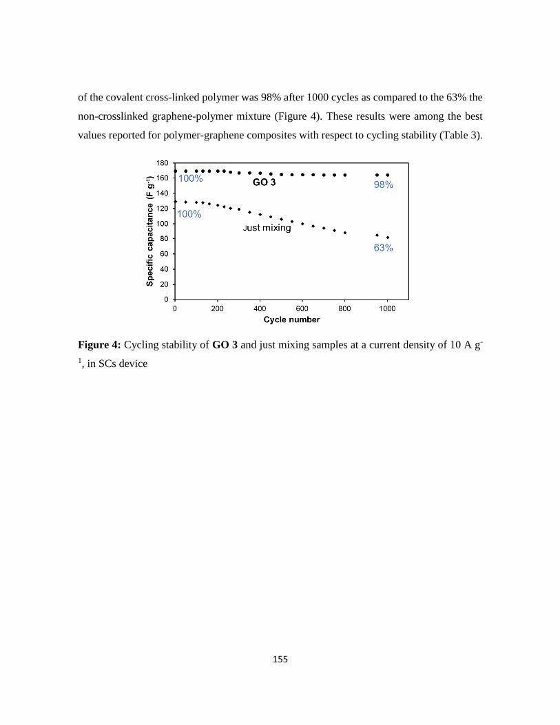
155
of the covalent cross-linked polymer was 98% after 1000 cycles as compared to the 63% the
non-crosslinked graphene-polymer mixture (Figure 4). These results were among the best
values reported for polymer-graphene composites with respect to cycling stability (Table 3).
Figure 4: Cycling stability of GO 3 and just mixing samples at a current density of 10 A g-
1, in SCs device
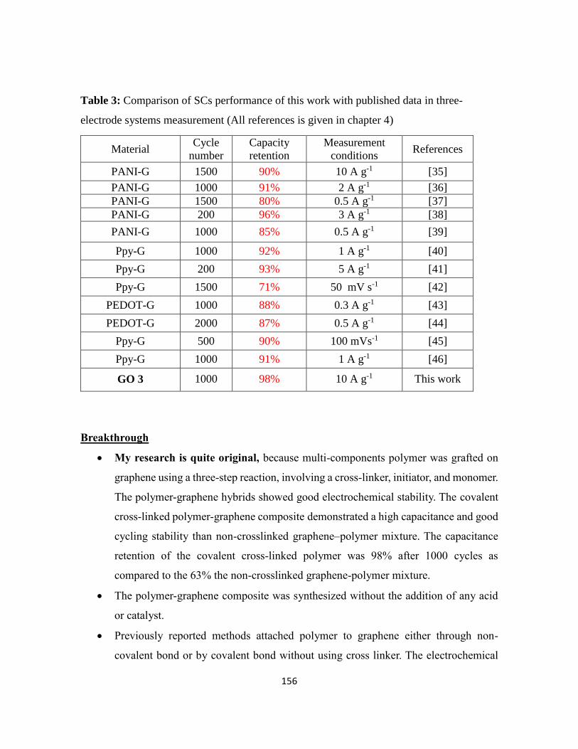
156
Table 3: Comparison of SCs performance of this work with published data in three-
electrode systems measurement (All references is given in chapter 4)
Breakthrough
My research is quite original, because multi-components polymer was grafted on
graphene using a three-step reaction, involving a cross-linker, initiator, and monomer.
The polymer-graphene hybrids showed good electrochemical stability. The covalent
cross-linked polymer-graphene composite demonstrated a high capacitance and good
cycling stability than non-crosslinked graphene–polymer mixture. The capacitance
retention of the covalent cross-linked polymer was 98% after 1000 cycles as
compared to the 63% the non-crosslinked graphene-polymer mixture.
The polymer-graphene composite was synthesized without the addition of any acid
or catalyst.
Previously reported methods attached polymer to graphene either through non-
covalent bond or by covalent bond without using cross linker. The electrochemical
Material Cycle
number
Capacity
retention
Measurement
conditions References
PANI-G 1500 90% 10 A g-1 [35]
PANI-G 1000 91% 2 A g-1 [36]
PANI-G 1500 80% 0.5 A g-1 [37]
PANI-G 200 96% 3 A g-1 [38]
PANI-G 1000 85% 0.5 A g-1 [39]
Ppy-G 1000 92% 1 A g-1 [40]
Ppy-G 200 93% 5 A g-1 [41]
Ppy-G 1500 71% 50 mV s-1 [42]
PEDOT-G 1000 88% 0.3 A g-1 [43]
PEDOT-G 2000 87% 0.5 A g-1 [44]
Ppy-G 500 90% 100 mVs-1 [45]
Ppy-G 1000 91% 1 A g-1 [46]
GO 3 1000 98% 10 A g-1 This work
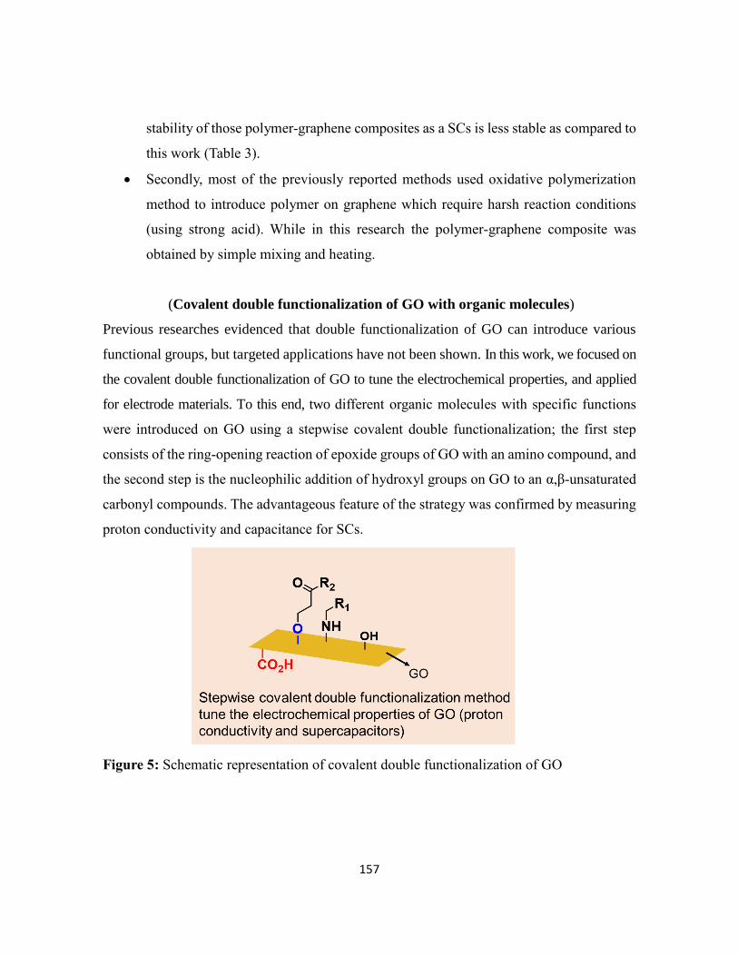
157
stability of those polymer-graphene composites as a SCs is less stable as compared to
this work (Table 3).
Secondly, most of the previously reported methods used oxidative polymerization
method to introduce polymer on graphene which require harsh reaction conditions
(using strong acid). While in this research the polymer-graphene composite was
obtained by simple mixing and heating.
(Covalent double functionalization of GO with organic molecules)
Previous researches evidenced that double functionalization of GO can introduce various
functional groups, but targeted applications have not been shown. In this work, we focused on
the covalent double functionalization of GO to tune the electrochemical properties, and applied
for electrode materials. To this end, two different organic molecules with specific functions
were introduced on GO using a stepwise covalent double functionalization; the first step
consists of the ring-opening reaction of epoxide groups of GO with an amino compound, and
the second step is the nucleophilic addition of hydroxyl groups on GO to an α,β-unsaturated
carbonyl compounds. The advantageous feature of the strategy was confirmed by measuring
proton conductivity and capacitance for SCs.
Figure 5: Schematic representation of covalent double functionalization of GO

158
Proton conductivity measurement
The role of covalent double functionalized GO was investigated in the proton conductivity.
Thus, the proton conductivity of the GO was improved by tuning the surface functional
groups. For this purpose, sulfanilic acid was grafted on GO through epoxide group (GO 3),
followed by the attachment of BQ molecules (GO 4). Sulfanilic acid act as proton conducting
material which are previously reported. For comparison, aniline was functionalized on GO
(GO 5) followed by the attachment of BQ (GO 6) (Figure 6). The prepared materials were
confirmed by XPS analysis.
The proton conductivity was evaluated by electrochemical impedance spectroscopy. The
Nyquist plot of GO 4 and GO 6 showed three types of resistance such as R, R1 and R2 (Figure
7a and 7b). The proton conductivity was calculated from the R values given by the electrical
circuit and considering the pellet thickness and surface area. The R value for GO 4 was 7.0
ohm (inset in Figure 7a), while the R value for GO 6 was 509.4 ohm (inset in Figure 7b).
The proton conductivity of GO 4, and GO 6 was 7 x 10⁻³ S cm-1 and 6 x 10⁻⁵ S cm-1
respectively. These results indicate that GO 4 showed good proton conductivity, which may
be due to the fast ion transportation, facilitating by sulfonic acid functional group.
Figure 6: Synthesis of GO 4, and GO 6
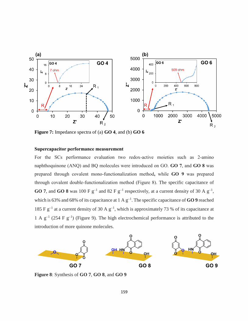
159
Figure 7: Impedance spectra of (a) GO 4, and (b) GO 6
Supercapacitor performance measurement
For the SCs performance evaluation two redox-active moieties such as 2-amino
naphthoquinone (ANQ) and BQ molecules were introduced on GO. GO 7, and GO 8 was
prepared through covalent mono-functionalization method, while GO 9 was prepared
through covalent double-functionalization method (Figure 8). The specific capacitance of
GO 7, and GO 8 was 100 F g1 and 82 F g1 respectively, at a current density of 30 A g1,
which is 63% and 68% of its capacitance at 1 A g1. The specific capacitance of GO 9 reached
185 F g1 at a current density of 30 A g1, which is approximately 73 % of its capacitance at
1 A g1 (254 F g1) (Figure 9). The high electrochemical performance is attributed to the
introduction of more quinone molecules.
Figure 8: Synthesis of GO 7, GO 8, and GO 9
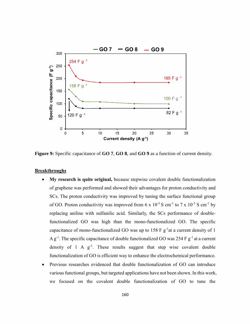
160
Figure 9: Specific capacitance of GO 7, GO 8, and GO 9 as a function of current density.
Breakthroughs
My research is quite original, because stepwise covalent double functionalization
of graphene was performed and showed their advantages for proton conductivity and
SCs. The proton conductivity was improved by tuning the surface functional group
of GO. Proton conductivity was improved from 6 x 10⁻⁵ S cm-1 to 7 x 10⁻³ S cm-1 by
replacing aniline with sulfanilic acid. Similarly, the SCs performance of double-
functionalized GO was high than the mono-functionalized GO. The specific
capacitance of mono-functionalized GO was up to 158 F g-1at a current density of 1
A g-1. The specific capacitance of double functionalized GO was 254 F g-1 at a current
density of 1 A g-1. These results suggest that step wise covalent double
functionalization of GO is efficient way to enhance the electrochemical performance.
Previous researches evidenced that double functionalization of GO can introduce
various functional groups, but targeted applications have not been shown. In this work,
we focused on the covalent double functionalization of GO to tune the

161
electrochemical properties. The advantageous feature of the strategy was confirmed
by measuring proton conductivity and capacitance for SCs.
Future prospective
The covalently bonded composites prevent the dissolution of small redox-active molecules,
stabilize the polymer structure, and shows better electrochemical stability than non-
covalently bonded ones. The literature survey reveals that comprehensive research has not
been done on the covalent functionalization of graphene-based materials for SCs and LIBs
applications, despite the development of various types of organic transformations in recent
years. Only a few traditional reactions have been employed for the functionalization of
graphene (Figure 10). Interestingly, there reported quite a limited number of papers on the
covalent functionalization of classic carbons, such as carbon black, ketjen black, and
activated carbon; most of the studies focused on the functionalization of novel nanocarbons,
such as graphene and CNTs. Therefore, further investigation is needed combining traditional
and latest chemical transformations and classical carbons and nanocarbons for developing
advanced electrochemical electrode materials.

162
Figure 10: Strategy and future research plan
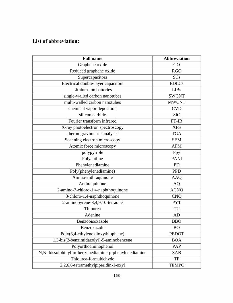
163
List of abbreviation:
Full name Abbreviation
Graphene oxide GO
Reduced graphene oxide RGO
Supercapacitors SCs
Electrical double-layer capacitors EDLCs
Lithium-ion batteries LIBs
single-walled carbon nanotubes SWCNT
multi-walled carbon nanotubes MWCNT
chemical vapor deposition CVD
silicon carbide SiC
Fourier transform infrared FT-IR
X-ray photoelectron spectroscopy XPS
thermogravimetric analysis TGA
Scanning electron microscopy SEM
Atomic force microscopy AFM
polypyrrole Ppy
Polyaniline PANI
Phenylenediamine PD
Poly(phenylenediamine) PPD
Amino-anthraquinone AAQ
Anthraquinone AQ
2-amino-3-chloro-1,4-naphthoquinone ACNQ
3-chloro-1,4-naphthoquinone CNQ
2-aminopyrene-3,4,9,10-tetraone PYT
Thiourea TU
Adenine AD
Benzobisoxazole BBO
Benzoxazole BO
Poly(3,4-ethylene dioxythiophene) PEDOT
1,3-bis(2-benzimidazolyl)-5-aminobenzene BOA
Polyorthoaminophenol PAP
N,N′-bissulphinyl-m-benzenediamine-p-phenylenediamine SAB
Thiourea-formaldehyde TF
2,2,6,6-tetramethylpiperidin-1-oxyl TEMPO

164
Tetrahydroxybenzoquinone THBQ
Nitroxide NO
Naphthalenediimide diamine NDIDA
N,N′-diamino-1,4,5,8-naphthalenetetracarboxylic bisimide DNTCB
Polysulfur PS
Poly(2,2,6,6-tetramethylpiperidinyloxy-4-ylmethacrylate PTMA
pyridine Py
diisopropylamine iPr2NH
trimethylamine Et3N
isoquinolinedione IQD
Energy-dispersive X-ray EDS
Open-circuit voltage OCV
cyclic voltammogram CV
Phosphate buffer saline PBS
Flavin adenine dinucleotide-glucose dehydrogenase FAD-GDH
Hydrobromic acid HBr
[bis(trifluoroacetoxy)iodo] benzene PIFA
N-methylpyrrolidone NMP
Polyvinylidene difluoride PVDF
2-amino naphthoquinone ANQ
1,4-benzoquinone BQ

165
List of publications
1. A simple and robust functionalization of graphene for advanced energy devices,
Rizwan Khan, Ryo Nakagawa, Benoit Campeon and Yuta Nishina,
ACS Appl. Mater. Interfaces, 2020, 12, 12736-12742.
2. Grafting conductive polymers on graphene oxide through cross-linker: a stepwise
approach,
Rizwan Khan, Yuta Nishina,
j. Mater. Chem. A, 2020, 8, 13718-13724.
3. Covalent functionalization of carbon materials with redox-active organic molecules
for energy storage, (Review paper)
Rizwan Khan, Yuta Nishina,
Nanoscale, 2021,13, 36-50.

166
This thesis is dedicated to my parents
For their endless love, support and encouragement

167
ACKNOWLEDGEMENT
All praises to Almighty Allah and His blessing for the completion of this study.
First and Foremost, I would like to express my sincere gratitude to my advisor Prof. Yuta
Nishina for the continuous support of my Ph.D. study and research. His guidance helped me
in all the time of research. His insightful feedback pushed me to sharpen my thinking and
brought my work to a higher level.
I wish to express my deepest gratitude to my dear friend Dr. Sohail Ahmad, who introduced
me to prof. Yuta Nishina and creating this thesis opportunity.
I would like to express my gratitude to Okayama University for giving me the opportunity
to complete this study.
I thank my laboratory members for their support and cooperation: Dr. Obata. Dr. Komoda,
Dr. Nakano, Dr. Azuma, Dr. Matsumura, Dr. Benoit, Dr. Sohail, Dr. Nizami, Mrs. Nusrat,
Mr. Cheng, Mr. Zhou, Ms. Hori, Mr. Fuji, Mr. Nakagawa, Mr. Takeda, Mr. Miyagawa, Mr.
Kubo, Mr. Iguchi, Ms. Shibahara, Mr. Kaji, Mr. Takahashi, Mrs. Tamagawa, Mrs. Ohkubo,
Dr. Uchida, and Mr.Tomita,
My sincere thank goes to Dr. Benoit, Mrs. Ohkubo, Dr. Azuma, Ms. Hori, Mr. Fuji, Mr.
Nakagawa, and Dr. Komoda for all of his help and assistance.
I wish to shows my gratitude to my master supervisor Dr. Maria Sadia for their
encouragement and support during my master study.
I would like to thank to my brothers: Taimor Khan, Uzair Khan, and Mansoor Khan. It
would not be possible to write this thesis without their support.

168
Last but not the least, I would like to thank to my mother, the most important person of my
life. She has been the source of inspiration and gave me strength in difficult times. She
continually provides their moral, spiritual, and emotional support. Thank you for everything.