Embed Size (px)
Citation preview
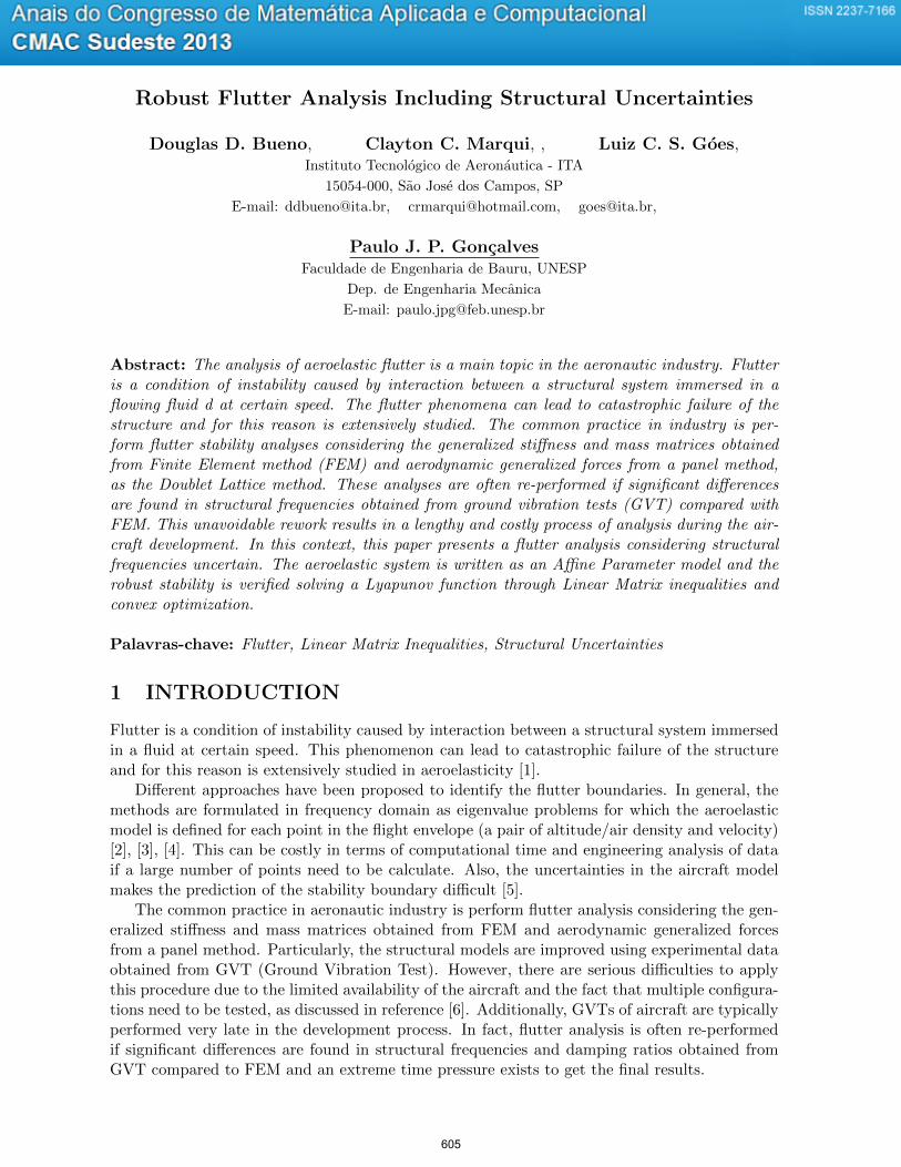
Robust Flutter Analysis Including Structural Uncertainties
Douglas D. Bueno, Clayton C. Marqui, , Luiz C. S. Goes,Instituto Tecnologico de Aeronautica - ITA
15054-000, Sao Jose dos Campos, SP
E-mail: [email protected], [email protected], [email protected],
Paulo J. P. GoncalvesFaculdade de Engenharia de Bauru, UNESP
Dep. de Engenharia Mecanica
E-mail: [email protected]
Abstract: The analysis of aeroelastic flutter is a main topic in the aeronautic industry. Flutteris a condition of instability caused by interaction between a structural system immersed in aflowing fluid d at certain speed. The flutter phenomena can lead to catastrophic failure of thestructure and for this reason is extensively studied. The common practice in industry is per-form flutter stability analyses considering the generalized stiffness and mass matrices obtainedfrom Finite Element method (FEM) and aerodynamic generalized forces from a panel method,as the Doublet Lattice method. These analyses are often re-performed if significant differencesare found in structural frequencies obtained from ground vibration tests (GVT) compared withFEM. This unavoidable rework results in a lengthy and costly process of analysis during the air-craft development. In this context, this paper presents a flutter analysis considering structuralfrequencies uncertain. The aeroelastic system is written as an Affine Parameter model and therobust stability is verified solving a Lyapunov function through Linear Matrix inequalities andconvex optimization.
Palavras-chave: Flutter, Linear Matrix Inequalities, Structural Uncertainties
1 INTRODUCTION
Flutter is a condition of instability caused by interaction between a structural system immersedin a fluid at certain speed. This phenomenon can lead to catastrophic failure of the structureand for this reason is extensively studied in aeroelasticity [1].
Different approaches have been proposed to identify the flutter boundaries. In general, themethods are formulated in frequency domain as eigenvalue problems for which the aeroelasticmodel is defined for each point in the flight envelope (a pair of altitude/air density and velocity)[2], [3], [4]. This can be costly in terms of computational time and engineering analysis of dataif a large number of points need to be calculate. Also, the uncertainties in the aircraft modelmakes the prediction of the stability boundary difficult [5].
The common practice in aeronautic industry is perform flutter analysis considering the gen-eralized stiffness and mass matrices obtained from FEM and aerodynamic generalized forcesfrom a panel method. Particularly, the structural models are improved using experimental dataobtained from GVT (Ground Vibration Test). However, there are serious difficulties to applythis procedure due to the limited availability of the aircraft and the fact that multiple configura-tions need to be tested, as discussed in reference [6]. Additionally, GVTs of aircraft are typicallyperformed very late in the development process. In fact, flutter analysis is often re-performedif significant differences are found in structural frequencies and damping ratios obtained fromGVT compared to FEM and an extreme time pressure exists to get the final results.
605
In this context, this paper presents an approach to perform flutter analysis including un-certainties in structural frequencies. The main goal is to assure the nominal system stabilityconsidering this modal parameter varying in a limited range previously assumed by experience.The aeroelastic system is written as an Affine Parameter model and the robust stability is ver-ified solving a Lyapunov function through LMI (Linear Matrix Inequalities). The method iswritten in time domain using a rational function approximation for the aerodynamic forces.This methodology offers promise for robust flutter analysis using convex optimization.
2 MATHEMATICAL MODEL
Classical flutter analysis is performed considering a second order model in generalized coordi-nates. This is a fundamental approach mainly to analyze large and complex structures. Thesystem of equations is projected on the structural eigenvector obtained without structural damp-ing. Then, the equation of motion is represented in Laplace domain as
s2Mmum(s) + sDmum(s) + Kmum(s) = qQm(mM , k)um(s) (1)
where the subscript m indicates the generalized domain, q = 12ρV
2 is the dynamic pressure,ρ is the air density and V is the airspeed. The matrix Mm is an identity matrix (using theeigenvector normalized by the modal mass) and the stiffness and damping matrices are bothdiagonal matrices respectively given by
Km(x, x) = λx = ω2x
Dm(x, x) = 2ξxωx, x = 1, ...,m(2)
Qm is a matrix of aerodynamic coefficients that is a function of the Mach Number andreduced frequency k and considered time invariant. Because this matrix has no Inverse ofLaplace Transform, a rational function approximation is used to write the aerodynamic forcesin time domain [9]. In this case, Eq. (3) contains a polynomial part representing the forceson the section acting directly connected to the displacements um(t) and their first and secondderivatives. Also, this equation has a rational part representing the influence of the wake actingon the section with a time delay.
Qm(s) =
2∑j=0
Qmjsj
(b
V
)j+
nlag∑j=1
Qm(j+2)
(s
s+ bV βj
)um(s) (3)
where s is the Laplace variable, nlag is the number of lag terms and βj is the jth lag parameter(j = 1, · · · , nlag).
The proposed approach is formulated specially for system which small variations in frequen-cies due to uncertainties of structural properties and modelling have not substantial impact ontheir structural modes. This assumption is commonly used by researchers in different methods[7] and [8]. It was considered valid for the example shown in this work and, mainly for complexstructures, it can be previously confirmed through numerical tests.
To formulate the problem including the uncertainties an affine parameter model is used.An affine parameter model is a special state space equation which some constant uncertainparameter have a fixed value that is known only approximately. Gahinet and his colleague [10]discuss details and advantages to use this approach and, in practice, the equation of motion iswritten as
E(θ)x(t) = AE(θ)x(t) (4)
where E(θ) and A(θ) are known matrices written as functions of the vector θ = (θ1, ..., θnθ) ∈Rnθ of real uncertain parameters θx ∈ [θminx , θmaxx ], x = 1, ..., nθ; and
AE = A0 + θ1Aθ1 + ...+ θnθAθnθ(5)
606
In this work the robust aeroelastic quadratic stability is verified considering that m structuralfrequencies are uncertain and can vary in a limited range, as shown in the following equations
ωuncx = ωx + ∆ωxξuncx = ξx + ∆ξxx = 1, ..., m ≤ m
(6)
where ωx and ξx are their nominal values computed by FEM.
3 Robust Stability Analysis
Linear matrix inequalities (LMI) have been extensively applied in modern control theory [11].LMI contributed to overcome many difficulties in control design. In the last decade, LMIs havebeen used to solve many problems that until then was unfeasible through others methodologies,due mainly to the emerging of powerful algorithms to solve convex optimization problem, asfor instance, the interior point method [11] and [10]. There are few studies involving LMIs tosolve problem in aeroelastic fields and this work introduces an extension of the ideas previouslydiscussed in references [12].
Based on LMI, a sufficient condition for the quadratic stability of Affine system representedby x(t) = E−1
0 A(θ) is the existence of m+ 1 symmetric matrices Pi such that [10]
A(θ)TP(θ) + P(θ)A(θ) < 0, ∀ θ ∈ νP(θ) > I, ∀ θ ∈ ν
ATi Pi + PiAi > 0, ∀ i = 1, ..., m ∈ ν
(7)
where ν denotes a set of vertices of a hiperrectangle and P(θ) := P0+θ1P1+...+θmPm. Gahinetet al. [10] show if this LMI system is feasible, the quadratic stability is assured for all values ofθx in [θminx , θmaxx ], where θminx = θx (1−Θδθx) and θmaxx = θx (1 + Θδθx), ∀ x = 1, ..., m. Notethat E0 is a non-singular matrix; otherwise see reference [13].
Since the quadratic stability is a sufficient condition, this approach computes the range whichthe parameters can vary keeping the system stable. However, it does not necessarily computethe largest variation that is possible.
3.1 Structural Frequencies Uncertainties
Consider an undamped system (Dm is a null matrix) with uncertainties in its m elastic frequen-cies ωx, x = 1, .., m. Since each xth frequency is written as its square into the generalized stiffnessmatrix, the approach is mathematically formulated considering the parameter θuncx = (ω2
x)unc.This notation allows to write the aeroelastic matrix as shown bellow
AE = A0 + (ω21)uncAω1 + ...+ (ω2
m)uncAωm (8)
and the system described by Eq. (4) is written such that
E0 =
Mam 0 · · · 00 I 0 · · ·
0 · · · . . . · · ·0 · · · 0 I
(9)
Mam = Mm − q(b
V
)2
Qm2 (10)
607
A0 =
q bV Qm1 −
(Km − qQm0
)qQm3 · · · qQm(2+nlag)
I 0 0 · · · 0
I 0 −Vb Iβ1 0 · · ·
......
.... . . · · ·
I 0 0 · · · −Vb Iβnlag
(11)
where Km is the modal stiffness matrix setting zero for each xth frequency considered uncertain.For each matrix Aωx ∈ m(2 + nlag) ×m(2 + nlag) in Eq. (5), the element a(x,x+m) = −1 andthe other ones are zero. Note that each of these matrices have only one non-zero element andeach Eωx are null matrices. The uncertain parameter (ωuncx )2 is defined in a continuous rangethrough its minimum and maximum values according to the following equation
(ωuncx )2 = ω2x(1± δωx) such that,
(ωuncx )2min = ω2
x(1− δωx)(ωuncx )2
max = ω2x(1 + δωx)
x = 1, ..., m
(12)
where δωx is the percentage of uncertainty in the xth eigenvalue λx (or ω2x). It is possible
to rewrite Eq. (12) introducing the parameter Θ > 0 for computing the largest portion of thespecified parameter range θx ∈ [θminx , θmaxx ] where quadratic stability is assured, as shown bellow
(ωuncx )2min = ω2
x(1−Θδx)(ωuncx )2
max = ω2x(1 + Θδx)
(13)
In this case, the aeroelastic quadratic stability is assured considering that each xth structuralfrequency can vary τωx percent with respect to its nominal value, where
τωx = 102[(1±Θδωx)1/2 − 1
](14)
Note that ωuncx = ωx[1± 10−2τωx ]; and δωx is previously defined to solve an LMI system and Θis an output.
4 NUMERICAL APPLICATION
To illustrate the effectiveness of the method, numerical simulations were developed on a bench-mark wing structure AGARD 445.6 shown in reference [14]. The linear structural model for theAGARD 445.6 wing was created using the MSC/NASTRAN program. The wing is modelled withplate elements as a single layer orthotropic material consisting of 231 nodes and 200 elements.The thickness distribution was governed by the airfoil shape. The material properties used areE1 = 3.1511 GPa, E2 = 0.4162 GPa, ν = 0.31, G = 0.4392 GPa and ρmat = 381.98 kg/m3,where E1 and E2 are the moduli of elasticity in the longitudinal and lateral directions respec-tively, the ν is Poisson’s ratio, G is the shear modulus in each plane and ρmat is the mass density.Small damping loss factor was considered using ξ = .01 for all natural frequencies.
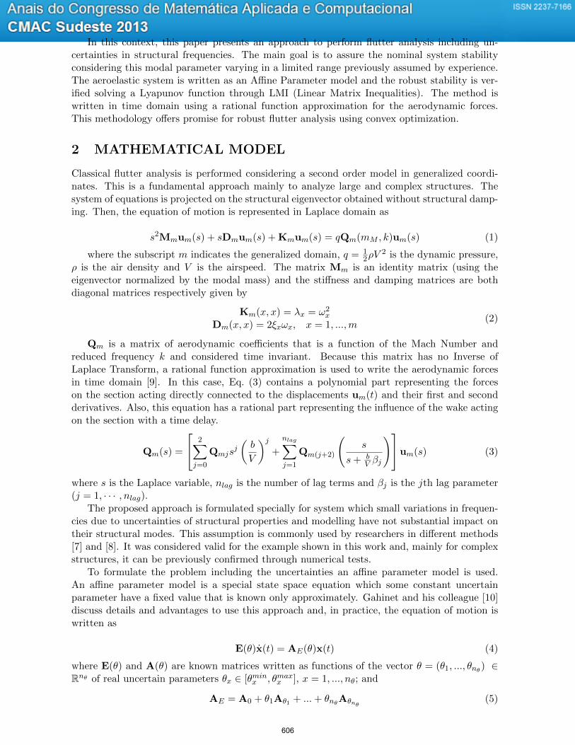
Aerodynamic and structural matrices are obtained by MSC/NASTRAN program (from so-lution 145) for Mach number 0.50 and ρREF = 1.225 kg/m3 (air density). Figure 1 presents theflight envelope considered to illustrate this application showing the discrete points where theanalysis was performed. This figure also shows the boundaries of stability of flutter. The valuesof reduced frequencies are 10−3, 2.10−3, 5.10−3, 10−2, 5.10−2, 0.1, 0.2, 0.3, 0.5, 0.6, 0.8, 1.0, 1.5,2.0, 3.0 and 4.0. The model has a length of reference 2b = 0.5578 m, a sweep angle is 45 degreesat the quarter chord line, a semi-span of 0.762 m and a taper ratio of 0.66. The flutter boundaryis investigated using the first four fundamental structural modes (m = 4). Their natural fre-quencies (V = 0) are ω1 = 9.45 Hz, ω2 = 39.69 Hz, ω3 = 49.45 Hz and ω4 = 95.10 Hz. A state
608
145 150 155 160 165 1700
0.2
0.4
0.6
0.8
1
1.2
Airspeed (m/s)
Air
density
(kg/m
3)
Flight Envelope - Mach No. 0.50
unstablestable
air density 0.6527
airspeed 158.02
Figure 1: Flight envelope corresponding to the Mach number 0.50.
space model in time domain was obtained using four parameters of lag β1 = 0.55, β2 = 1.40,β3 = 1.90 and β4 = 2.90.
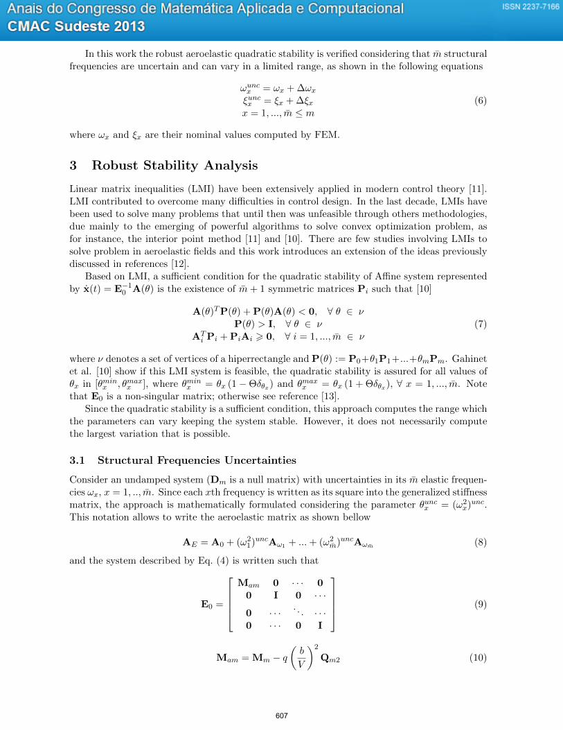
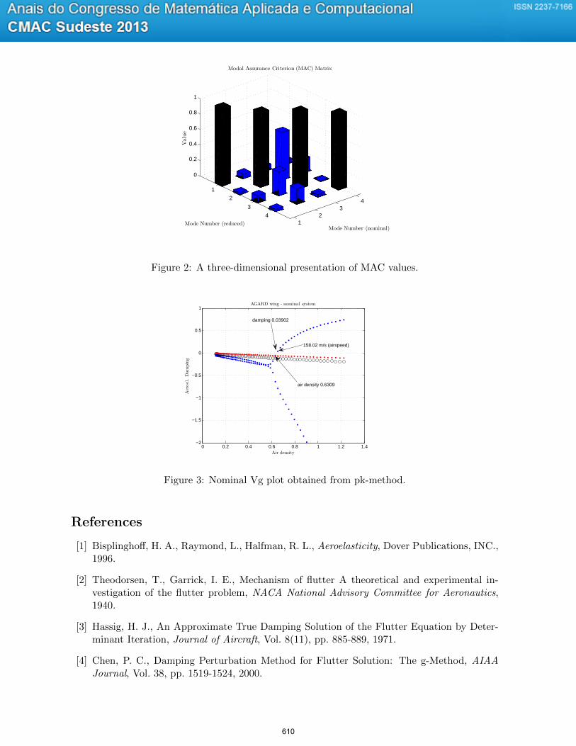
To apply the approach is verified that the structural modes are not significantly affected bythe uncertainties considered during the analysis. This is an assumption to assure the resultsspecially for systems represented by equation of motion written in the generalized coordinatesystem with modal truncation, however, it is not required for small systems written in thephysical coordinate system. For the system presented in this work that behavior was verifiedby computing the modal assurance criterion (MAC) using the structural eigenvectors obtainedfrom different values of longitudinal modulus of elasticity. The particular example shown inFig. 2 demonstrates that two sets of eigenvectors are consistent when the structural frequenciesare not their nominal values (see Table 1). The MAC is a index that shows how the eigenvectorscorrelate, for perfect correlation, one would obtain the identity matrix, and in this case, althoughthere are difference in the material properties and variation in the natural frequencies, theeigenvectors are still very similar..
Table 1: Structural frequencies for two different longitudinal moduli of elasticity.Mode Freq. (Hz) Freq. (Hz) VariationNo. E1 (nominal) E1 = 2.50GPa (%)
1 9.45 8.49 −10.192 39.69 37.15 −6.413 19.45 47.04 −4.874 95.10 89.33 −6.06
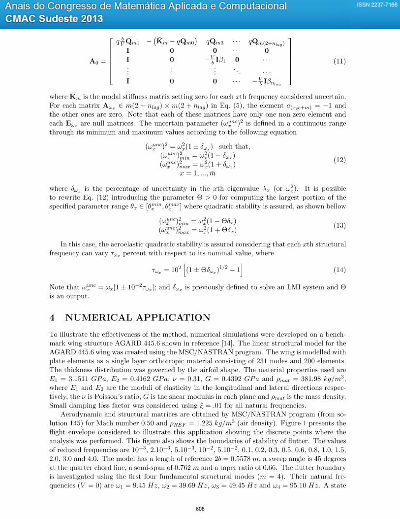
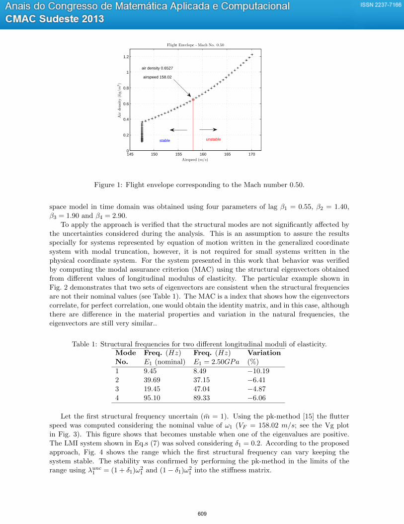
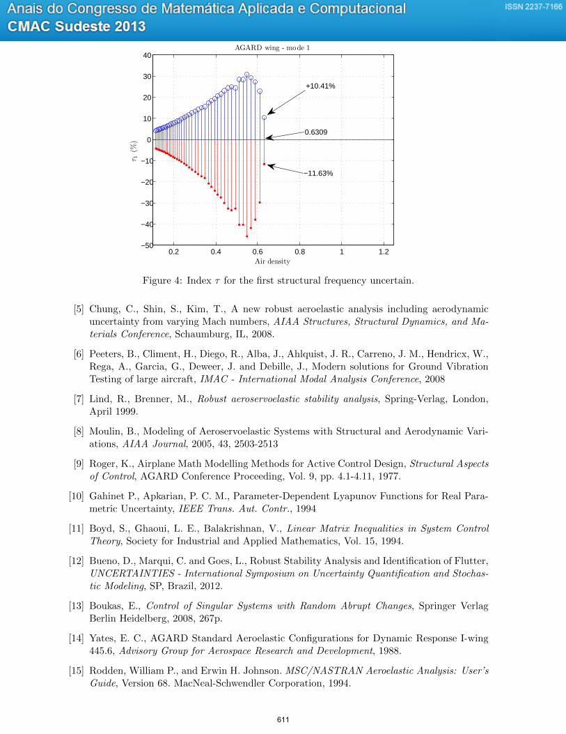
Let the first structural frequency uncertain (m = 1). Using the pk-method [15] the flutterspeed was computed considering the nominal value of ω1 (VF = 158.02 m/s; see the Vg plotin Fig. 3). This figure shows that becomes unstable when one of the eigenvalues are positive.The LMI system shown in Eq.s (7) was solved considering δ1 = 0.2. According to the proposedapproach, Fig. 4 shows the range which the first structural frequency can vary keeping thesystem stable. The stability was confirmed by performing the pk-method in the limits of therange using λunc1 = (1 + δ1)ω2
1 and (1− δ1)ω21 into the stiffness matrix.
609
12
34
1
2
3
4
0
0.2
0.4
0.6
0.8
1
Mode Number (nominal)
Modal Assurance Criterion (MAC) Matrix
Mode Number (reduced)
Value
Figure 2: A three-dimensional presentation of MAC values.
0 0.2 0.4 0.6 0.8 1 1.2 1.4−2
−1.5
−1
−0.5
0
0.5
1
Air density
AGARD wing - nominal system
Aeroel.Damping
damping 0.03902
air density 0.6309
158.02 m/s (airspeed)
Figure 3: Nominal Vg plot obtained from pk-method.
References
[1] Bisplinghoff, H. A., Raymond, L., Halfman, R. L., Aeroelasticity, Dover Publications, INC.,1996.
[2] Theodorsen, T., Garrick, I. E., Mechanism of flutter A theoretical and experimental in-vestigation of the flutter problem, NACA National Advisory Committee for Aeronautics,1940.
[3] Hassig, H. J., An Approximate True Damping Solution of the Flutter Equation by Deter-minant Iteration, Journal of Aircraft, Vol. 8(11), pp. 885-889, 1971.
[4] Chen, P. C., Damping Perturbation Method for Flutter Solution: The g-Method, AIAAJournal, Vol. 38, pp. 1519-1524, 2000.
610
0.2 0.4 0.6 0.8 1 1.2−50
−40
−30
−20
−10
0
10
20
30
40
Air density
AGARD wing - mode 1
τ 1(%
)
+10.41%
−11.63%
0.6309
Figure 4: Index τ for the first structural frequency uncertain.
[5] Chung, C., Shin, S., Kim, T., A new robust aeroelastic analysis including aerodynamicuncertainty from varying Mach numbers, AIAA Structures, Structural Dynamics, and Ma-terials Conference, Schaumburg, IL, 2008.
[6] Peeters, B., Climent, H., Diego, R., Alba, J., Ahlquist, J. R., Carreno, J. M., Hendricx, W.,Rega, A., Garcia, G., Deweer, J. and Debille, J., Modern solutions for Ground VibrationTesting of large aircraft, IMAC - International Modal Analysis Conference, 2008
[7] Lind, R., Brenner, M., Robust aeroservoelastic stability analysis, Spring-Verlag, London,April 1999.
[8] Moulin, B., Modeling of Aeroservoelastic Systems with Structural and Aerodynamic Vari-ations, AIAA Journal, 2005, 43, 2503-2513
[9] Roger, K., Airplane Math Modelling Methods for Active Control Design, Structural Aspectsof Control, AGARD Conference Proceeding, Vol. 9, pp. 4.1-4.11, 1977.
[10] Gahinet P., Apkarian, P. C. M., Parameter-Dependent Lyapunov Functions for Real Para-metric Uncertainty, IEEE Trans. Aut. Contr., 1994
[11] Boyd, S., Ghaoui, L. E., Balakrishnan, V., Linear Matrix Inequalities in System ControlTheory, Society for Industrial and Applied Mathematics, Vol. 15, 1994.
[12] Bueno, D., Marqui, C. and Goes, L., Robust Stability Analysis and Identification of Flutter,UNCERTAINTIES - International Symposium on Uncertainty Quantification and Stochas-tic Modeling, SP, Brazil, 2012.
[13] Boukas, E., Control of Singular Systems with Random Abrupt Changes, Springer VerlagBerlin Heidelberg, 2008, 267p.
[14] Yates, E. C., AGARD Standard Aeroelastic Configurations for Dynamic Response I-wing445.6, Advisory Group for Aerospace Research and Development, 1988.
[15] Rodden, William P., and Erwin H. Johnson. MSC/NASTRAN Aeroelastic Analysis: User’sGuide, Version 68. MacNeal-Schwendler Corporation, 1994.
611