Embed Size (px)
Citation preview

9
Robust Control of Electro-Hydraulic Actuator Systems Using the Adaptive Back-Stepping
Control Scheme
Jong Shik Kim, Han Me Kim and Sung Hwan Park School of Mechanical Engineering, Pusan National University
Republic of Korea
1. Introduction
Conventional hydraulic actuator (CHA) systems have been widely used as power units
because they can generate very large power compared to their size. In general, a CHA
system consists of an electric motor, a pump, a reservoir, various valves, hoses, which are
used to transfer the working fluid and an actuator. CHA systems, however, have some
problems such as environmental pollution caused by the leakage of the working fluid,
maintenance load, heavy weight and limited installation space. These shortcomings can be
overcome by compactly integrating the components of CHA systems and by applying a
suitable control scheme for the electric motor. To overcome these shortcomings of CHA
systems, electro-hydraulic actuator (EHA) systems have been developed, having merits such
as smaller size, higher energy efficiency and faster response than existing CHA systems
(Kokotovic, 1999). However, for the robust position control of EHA systems, system
uncertainties such as the friction between the piston and cylinder and the pump leakage
coefficient have to be considered.
To solve these system uncertainty problems of EHA systems and to achieve the robustness
of EHA systems with system disturbance and bounded parameter uncertainties, Wang et. al.
presented a sliding mode control and a variable structure filter based on the variable
structure system (Wang, 2005). Perron et. al proposed a sliding mode control scheme for the
robust position control of EHA systems showing volumetric capacity perturbation of the
pump (Perron, 2005). However, these control methods have some chattering problem due to
the variable structure control scheme. The chattering vibrates the system and may reduce
the life cycle of the system. Jun et. al. presented a fuzzy logic self-tuning PID controller for
regulating the BLDC motor of EHA systems which has nonlinear characteristics such as the
saturation of the motor power and dead-zone due to the static friction (Jun, 2004). Chinniah
et. al. used a robust extended Kalman filter, which can estimate the viscous friction and
effective bulk modulus, to detect faults in EHA systems (Chinniah, 2006). Kaddissi et. al.
applied a robust indirect adaptive back-stepping control (ABSC) scheme to EHA systems
having perturbations of the viscous friction coefficient and the effective bulk modulus due
to temperature variations (Kaddissi, 2006). However, in spite of the variation of the effective
bulk modulus due to the temperature and pressure variations, Chinniah et. al. considered
www.intechopen.com

Challenges and Paradigms in Applied Robust Control
190
only the case of constant effective bulk modulus and Kaddissi et. al. used EHA systems that
are not controlled by an electric motor but by a servo valve.
In this chapter, an ABSC scheme was proposed for EHA systems to obtain the desired tracking performance and the robustness to system uncertainties. Firstly, to realize a stable back-stepping control (BSC) system with a closed loop structure and to select new state variables, EHA system dynamics are represented with state equations and error equations. Defining the Lyapunov control functions, we can design a BSC system, which can guarantee exponential stability for the nominal system without system uncertainties. However, the BSC system cannot achieve robustness to system uncertainties. To overcome the drawback of the BSC system, an ABSC scheme for EHA position control systems with classical discrete disturbance observer was proposed. To evaluate the tracking performance and robustness of the proposed EHA position control system, both BSC and ABSC schemes were evaluated by computer simulation and experiment.
2. System modeling of EHA system
Figure 1 shows the simplified schematic diagram of an EHA system that consists of an electric servo motor, bi-directional gear pump and actuator. The servo motor rotates the gear pump, which, in turn, generates the flow rate. The pressure generated by the flow rate changes the position of the piston rod. The movement direction of the piston is related to the rotational direction of the servo motor. The chamber volumes of the actuator depend on the cross sectional area and the displacement of the piston as follows
0
0
( ) ( )
( ) ( )A A
B B
V t V Ax t
V t V Ax t
(1)
Fig. 1. Simplified schematic diagram of an EHA system
www.intechopen.com
Robust Control of Electro-Hydraulic Actuator Systems Using the Adaptive Back-Stepping Control Scheme
191
where V and 0V are the chamber volume and the initial chamber volume, respectively, A
and x are the pressure area of a double rod hydraulic cylinder and displacement of the
piston, respectively, and subscripts ‘A’ and ‘B’ denote the chamber notations of the actuator. Considering the fluid compressibility and continuity principle for the actuator, the flow rate equations of both ports of the actuator can be represented as (Merritt, 1967)
0
0
AA A A
e
BB B B
e
V AxQ Ax P LP
V AxQ Ax P LP
(2)
where Q is the flow rate in the actuator, e is the effective bulk modulus of the working
fluid, and L and P are the actuator external leakage coefficient and the pressure in the
chamber, respectively. It is assumed that there is no fluid leakage of conduits because the conduits of EHA systems are very short and hard. Then, (2) can be expressed as
0
0
AA A
e
BB B
e
V AxQ Ax P
V AxQ Ax P
(3)
The electric motor, directly connected to the hydraulic pump, changes the flow direction and adjusts the flow rate through the ports. In addition, the pressure generated by the continuous supply of flow in the actuator can produce a minute fluid leakage of the pump. Hence, the equations for the fluid leakage of the pump are expressed as
a p p f L
b a
Q C L P
Q Q
(4)
where Q is the flow rate of the pump, whose subscripts a and b denote the ports of the
pump, pC is the volumetric capacity of the pump, p is the rotational velocity of the electric
motor, fL is the leakage factor of the pump and the load pressure L A BP P P . From (4),
the inflow and outflow of the pump are expressed as functions of the rotational velocity p . In addition, the actuator dynamic equation of EHA systems is expressed as
( )A B f exP P A M x F F (5)
where M and x are the mass and displacement of the piston, respectively, fF is the
friction force between the cylinder and piston and exF is the external disturbance force. In order to substitute (3) into (5), the derivative of (5) is expressed as
( )A B f exP P A M x F F (6)
In addition, it is assumed that the conduits connected between the actuator ports and the
pump ports are very short. Then, the flow rates in (3) and (4) can be represented as A aQ Q
www.intechopen.com

Challenges and Paradigms in Applied Robust Control
192
and B bQ Q . Substituting (1) through (4) into (6), therefore, the dynamic equation of EHA
systems can be represented as
21 1 1 1 1ee f ex f L p p
A B A B
Ax A x F F L P C
M V V M V V
(7)
To represent the characteristics of the friction fF between the piston and cylinder, the
LuGre friction model is considered. The LuGre friction model is based on bristles analysis,
which is represented with the average deflection force of bristles stiffness. The deflection
displacement equation of bristles z , which is actually unmeasurable by experiment, is
expressed as (Choi, 2004)(Lee, 2004)
0| |
( )
xdzx z
dt g x
(8)
where 0 is the bristles stiffness coefficient, z is the unmeasurable internal state and the
nonlinear function ( )g x depends on the material property, grade of lubrication and
temperature; that is
2( / )( ) svx v
c sg x F F e (9)
where cF , sF and svv represent the Coulomb friction force, static friction force, and Stribeck
velocity between the cylinder and piston, respectively.
If the relative velocity of the contact materials increases gradually, the friction force
decreases instantaneously and then it increases gradually again; this effect is called the
Stribeck effect and the relative velocity is the Stribeck velocity. This phenomenon depends
on the material property, grade of lubrication and temperature. The friction force fF can be
represented with the average deflection z and the velocity of the piston x as follows
0 1fF z z x (10)
where 1 and represent the bristles damping and viscous friction coefficients,
respectively.
3. Controller design for the EHA position control systems
The EHA position control system consists of the inner loop for the angular velocity control of the servo motor/pump and the outer loop for the position control of the piston. For the velocity control of the motor in the inner loop, Kokotovic et al. applied an adaptive control scheme so that the EHA position control systems can have robustness (Kokotovic, 1999). Habibi et. al. presented that if the inner loop dynamics are stable, the control gains of the PID velocity controller in the inner loop can have relatively large values and then the disturbance effect can be sufficiently rejected (Habibi, 1999). The velocity controller in the inner loop is very important because it regulates the electric motor. However, the case of (Kokotovic, 1999) is very complicated and the case of (Habibi, 1999), although it is theoretically possible, has a physical limitation that increases the control gains of the inner loop controller. Therefore, it is desirable to handle the controller in the outer loop rather
www.intechopen.com
Robust Control of Electro-Hydraulic Actuator Systems Using the Adaptive Back-Stepping Control Scheme
193
than in the inner loop to improve the performance and robustness of EHA position control systems. In this chapter, the BSC and ABSC schemes based on EHA system dynamics are considered as the position controller. Firstly, to design a BSC system, (7) is transformed to a general form (Slotine, 1999) as follows
x f bu (11)
where
21 1 1 1 1,e f ex e f L
A B A B
f A x F F L A PM V V V V
( ),
e A B p
A B
A V V Cb
MV V
pu
Now, let (11) represent state equations as follows
1 2
2 3
3
x x
x x
x f bu
(12)
And, in order to design the BSC system, new state variables are defined as follows
1 1 dz x x (13)
2 2 1 1( )z x z (14)
3 3 2 1 2( , )z x z z (15)
where dx is the desired position input, and 1 and 2 are the functions for new state
variables, which can be obtained through the following BSC design procedure. Step 1.
From (13), the state equation for 1z can be described as
1 2 1 1( ) dz z z x (16)
1 1( )z is the virtual control which should be selected to guarantee the stability of the control
system through the Lyapunov control function(LCF) which is defined as
21 1 1
1( )
2V z z (17)
Then,
1 1 1 1 1 1 1 1 2( ) [ ( ) ]dV z z z z z x z z (18)
From (18), if 1 1 1 1( ) dz k z x , (16) can be exponentially stable when t . And 1( 0)k
is a design parameter.
www.intechopen.com

Challenges and Paradigms in Applied Robust Control
194
Step 2.
From (14), the state equation for 2z can be described as
2 3 2 1 2 1 1( , ) ( )z z z z z (19)
where
1 11 1 1 1 1 1 2 1 1
1
( ) ( )d d dd
z z x k z x k z k z xz x
Since (19) includes the information of (16), the second LCF for obtaining the virtual control
to guarantee the stability of the control system can be selected as
22 1 2 1 1 2
1( , ) ( )
2V z z V z z (20)
Then,
22 1 2 1 1 2 2 1 1 2 3 2 1 2 1 2 1 1( , ) ( ) [ ( , ) ( )]V z z V z z z k z z z z z z z z (21)
If the virtual control 2 in the last term of (21) is defined as
2 1 2 2 2 1 1 1( , ) ( )z z k z z z
where 2( 0)k is a design parameter, then another expression of 2 can be rearranged as
22 1 2 1 2 2 1 1( , ) ( ) (1 ) dz z k k z k z x (22)
Therefore
2 22 2 3 1 1 2 2V z z k z k z (23)
Step 3.
From (15), the state equation for 3z is described as
3 3 2 1 2 2 1 2( , ) ( , )z x z z f bu z z (24)
where
2 2 22 1 2 1 2 1 1 2 2 1
1 2 1
( , )z z z z z k zz z
(25)
and
21 1 11 1 2 1 1 1 2
1 2d d
d
z z x k z k z xz z x
(26)
Substituting (16), (19), and (26) into (25), (25) can be rearranged as
2
2 1 2 1 1 1 2 2( , ) ( 1) ( ) dz z k z k k z x (27)
www.intechopen.com

Robust Control of Electro-Hydraulic Actuator Systems Using the Adaptive Back-Stepping Control Scheme
195
Since (24) uses the information of 1z and 2z due to the property of the design procedure of
the back-stepping control, the third LCF for (15) can be defined as
23 1 2 3 2 1 2 3
1( , , ) ( , )
2V z z z V z z z (28)
Then,
2 2
3 1 2 3 2 3 3 1 1 2 2 3 2 2( , , ) ( )V z z z V z z k z k z z z f bu (29)
If the last term of (29) for satisfying the system stability is defined as
3 3 2 2k z z f bu (30)
then the BSC law can be selected as
2 3 3 2
1( )u k z z f
b (31)
From (31), if the information of f is assumed to be known, the negative semi-definite of 3V
can be obtained by substituting (31) into (29) as
2 2 23 1 2 3 2 3 3 1 1 2 2 3 3( , , ) 0V z z z V z z k z k z k z (32)
From (32), it is found that EHA position control systems using the BSC law of (31) can
guarantee exponential stability.
If system uncertainties can be exactly known, the BSC law of (31) can achieve the desired
tracking performance and the robustness to the system uncertainties of EHA systems.
However, the BSC law of (31) will cause a tracking error and does not achieve the
robustness to the system uncertainties because the value of f cannot be exactly known. To
improve the tracking performance and the robustness to the system uncertainties, the value
of f , in which system uncertainties are included , should be estimated.
Therefore, in this chapter, an ABSC scheme is proposed, which is the BSC scheme with the
estimator of f . In order to design the ABSC system, the BSC law of (31) is modified as
2 3 3 2
1 ˆ( )u k z z fb (33)
where f̂ is the estimator of the system uncertainties. Substituting (33) into (12), (12) is modified as
1 2
2 3
3 2 3 3 2
x x
x x
x f k z z
(34)
where ˆf f f .
www.intechopen.com

Challenges and Paradigms in Applied Robust Control
196
From (13), (14), and (15), these equations are the error equations for the velocity, acceleration
and jerk of the piston, which include 1 1( )z and 2 1 2( , )z z that guarantee the exponential
stability of EHA position control systems. Substituting these equations into (34), the error
dynamics can be represented as
1 2 1 1
2 3 2 2 1
3 3 3 2
z z k z
z z k z z
z f k z z
(35)
From (35), the LCF is defined as
2 2 2 24 1 2 3
1 1 1 1
2 2 2 2V z z z f (36)
where is a positive constant. The derivative of (36) can be described as
2 2 24 1 1 2 2 3 3 1 1 2 2 3 3 3
1 1( ) 0V z z z z z z ff k z k z k z f z f (37)
From (37), an estimation rule to guarantee the system stability can be obtained as
3f̂ f z (38)
Equation (38) uses the information of 3z , which depends on the information of 1z and 2z .
Therefore, (38) closely relates to 1 and 2 , which guarantee the stability of BSC systems.
However, (38) cannot be used to the estimation rule because the value of f is unknown. On
the other hand, if f is assumed as a lumped uncertainty, system uncertainty f can be
estimated by 3f̂ z . However, since the value of f for the EHA system is changed
according to the operating condition, it cannot be assumed as the lumped uncertainty.
Therefore, to obtain the value of f , the classical discrete disturbance observer scheme was
used. Assuming that the sampling rate of the control loop is very fast, the classical discrete
disturbance observer expressed by the difference equation is induced from (31) as follows
2 3 3 2( 1) ( ) ( ) ( ) ( )f k bu k k k z k z k (39)
To analyze the stability of the proposed control scheme, (38) is substituted into (37). Then,
2 2 2 T
4 1 1 2 2 3 3 0V k z k z k z z Kz (40)
where K is the diagonal matrix of 1k , 2k and 3k , T1 2 3=[ ]z z zz , and 4 0V if 0z .
If z is bounded, (40) can be defined as
T( ) 0t z Kz (41)
Integrating (41) from 0 to t , the following result can be obtained
www.intechopen.com

Robust Control of Electro-Hydraulic Actuator Systems Using the Adaptive Back-Stepping Control Scheme
197
4 40( ) ( (0), (0)) ( )
td V f V t z (42)
Applying Barbalat’s Lemma(Krstic, 1995) to (42), we can obtain that ( ) 0t as t .
Therefore,
40lim ( ) ( (0), (0))
t
td V f z (43)
4. Computer simulation
In order to evaluate the validity of the proposed control scheme for EHA position control systems, a sinusoidal reference input was considered as follows
sin(0.25 ) sin(0.05 ) [cm]dx t t (44)
This sinusoidal reference input is suitable for evaluating the tracking performance and the robustness of EHA position control systems because it reflects the various changes in the magnitudes of the velocity and position of the piston. Table 1 shows the system parameters of the EHA system which are used to computer simulation. Figure 2 shows the block diagram of the EHA position control system.
Notation Description Unit
0V Initial volume of the chamber 4 33.712 10 m
A Pressure area of the piston 3 25.58 10 m
M Piston mass 5 kg
e Effective bulk modulus 31.7 10 MPa
fL Leakage factor of the pump 16 33.16 10 m /Pa
0 Bristles stiffness coefficient 65.77 10 N/m
1 Bristles damping coefficient 42.28 10 N/m/s
maxp Maximum speed of the motor 178 rad/s
pC Volumetric capacity of the pump
6 31.591 10 m /rad
0 Coulomb friction coefficient 370 N
1 Static friction 217 N
2 Viscous friction coefficient 2318 N/m/s
svv Stribeck velocity 0.032 m/s
Table 1. System parameters of the EHA
www.intechopen.com

Challenges and Paradigms in Applied Robust Control
198
Fig. 2. Block diagram of the EHA position control system
Figure 3 shows the tracking errors of the BSC and ABSC systems for the sinusoidal
reference. This result shows that the ABSC system has better tracking performance than the
BSC system and has error repeatability precision of higher reliability than the BSC system.
In addition, in both position and control schemes relatively large tracking errors occur at the
nearly zero velocity regions. This is due to the effect of dynamic friction characteristics,
which produce an instantaneous large force at the nearly zero velocity regions. For the
transient response region of the initial operation of EHA position control systems, the ABSC
system with the estimator for system uncertainties yields approximately 40% improvement
compared with the BSC system without the estimator because the f in (31) including
system uncertainties is estimated by (43), as shown in Fig. 4. Figure 4 shows the estimated
value f̂ for the system uncertainties of EHA systems obtained by the proposed adaptive
rule. The estimated value plat a role in the consideration of nonlinearity and uncertainties
included in EHA systems.
Fig. 3. Tracking errors of the BSC and ABSC systems for the sinusoidal reference input
www.intechopen.com
Robust Control of Electro-Hydraulic Actuator Systems Using the Adaptive Back-Stepping Control Scheme
199
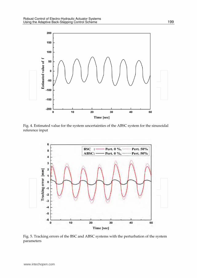
Fig. 4. Estimated value for the system uncertainties of the ABSC system for the sinusoidal reference input
Fig. 5. Tracking errors of the BSC and ABSC systems with the perturbation of the system parameters
www.intechopen.com

Challenges and Paradigms in Applied Robust Control
200
Figure 5 shows the tracking errors of the BSC and ABSC systems having perturbations of the system parameters such as the Coulomb friction, viscous friction and pump leakage coefficient in the EHA system for the sinusoidal reference input. It was assumed that the system parameters have a perturbation of 50%. From Fig. 5, it was found that the perturbations of the system parameters of the EHA system are closely related with the tracking performance of the EHA system. Table 2 shows the tracking RMS errors of the BSC and ABSC systems according to the perturbation of the system parameters. The variations of the tracking RMS errors due to the 50% perturbation of the system parameters for the BSC and ABSC systems are 17.6% and 3.02%, respectively. These results show that the proposed position control scheme has the desired robustness to system uncertainties such as the perturbation of the viscous friction, Coulomb friction and pump leakage coefficient.
Control scheme Perturbation ratio RMS value
BSC 0% 1.878 mm
50% 2.209 mm
ABSC 0% 0.265 mm
50% 0.273 mm
Table 2. Tracking RMS errors of the BSC and ABSC systems according to the perturbations of the system parameters
5. Experimental results and discussion
Figure 6 shows the experimental setup of the EHA system. To evaluate the effectiveness of the proposed control system, the PCM-3350(AMD Geode processor, 300MHz) was used. The control algorithms were programmed by Turbo-C++ language on MS-DOS, in order to directly handle the PCM-3718 as a data acquisition board. The PCM-3718 is a fully multifunctional card with PC/104 interface. In addition, to measure the position of the piston, an LVDT(linear variable differential transformer) sensor was used. The sampling rate was set to 1 kHz.
Fig. 6. Experimental setup of the EHA system
www.intechopen.com
Robust Control of Electro-Hydraulic Actuator Systems Using the Adaptive Back-Stepping Control Scheme
201
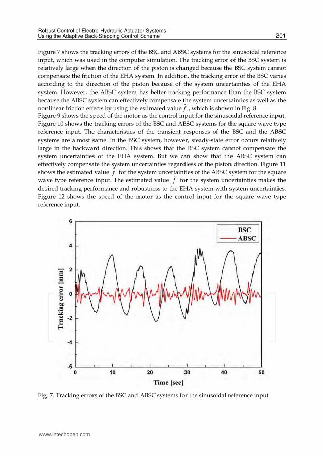
Figure 7 shows the tracking errors of the BSC and ABSC systems for the sinusoidal reference
input, which was used in the computer simulation. The tracking error of the BSC system is
relatively large when the direction of the piston is changed because the BSC system cannot
compensate the friction of the EHA system. In addition, the tracking error of the BSC varies
according to the direction of the piston because of the system uncertainties of the EHA
system. However, the ABSC system has better tracking performance than the BSC system
because the ABSC system can effectively compensate the system uncertainties as well as the
nonlinear friction effects by using the estimated value f̂ , which is shown in Fig. 8. Figure 9 shows the speed of the motor as the control input for the sinusoidal reference input.
Figure 10 shows the tracking errors of the BSC and ABSC systems for the square wave type
reference input. The characteristics of the transient responses of the BSC and the ABSC
systems are almost same. In the BSC system, however, steady-state error occurs relatively
large in the backward direction. This shows that the BSC system cannot compensate the
system uncertainties of the EHA system. But we can show that the ABSC system can
effectively compensate the system uncertainties regardless of the piston direction. Figure 11
shows the estimated value f̂ for the system uncertainties of the ABSC system for the square
wave type reference input. The estimated value f̂ for the system uncertainties makes the
desired tracking performance and robustness to the EHA system with system uncertainties.
Figure 12 shows the speed of the motor as the control input for the square wave type
reference input.
Fig. 7. Tracking errors of the BSC and ABSC systems for the sinusoidal reference input
www.intechopen.com

Challenges and Paradigms in Applied Robust Control
202
Fig. 8. Estimated value for the system uncertainties of the ABSC system for the sinusoidal reference input
Fig. 9. Speed of the motor as the control input for the sinusoidal reference input
www.intechopen.com

Robust Control of Electro-Hydraulic Actuator Systems Using the Adaptive Back-Stepping Control Scheme
203
Fig. 10. Tracking errors of the BSC and ABSC systems for the square wave type reference input
Fig. 11. Estimated value for the system uncertainties of the ABSC system for the square wave type reference input
www.intechopen.com

Challenges and Paradigms in Applied Robust Control
204
Fig. 12. Speed of the motor as the control input for the square wave type reference input
www.intechopen.com

Robust Control of Electro-Hydraulic Actuator Systems Using the Adaptive Back-Stepping Control Scheme
205
Table 3 shows the tracking RMS errors of the BSC and ABSC systems for the sinusoidal reference input and the square wave type reference input at steady-state. From Table 3, it was found that using the ABSC system instead of the BSC system yields about 5 times improvement in the tracking performance of the EHA position control system.
Control system Sinusoidal reference input Square wave type reference
input at steady state
BSC 1.762 mm 0.395 mm
ABSC 0.309 mm 0.114 mm
Table 3. Tracking RMS errors of the BSC and ABSC systems
6. Conclusion
A robust position control of EHA systems was proposed by using the ABSC scheme, which has robustness to system uncertainties such as the perturbation of viscous friction, Coulomb friction and pump leakage coefficient. Firstly, a stable BSC system based on the EHA system dynamics was derived. However, the BSC scheme had a drawback: it could not consider system uncertainties. To overcome the drawback of the BSC scheme, the ABSC scheme was proposed having error equations for the velocity, acceleration and jerk of the piston, respectively, which were induced by the BSC scheme. To evaluate the performance and robustness of the proposed EHA position control system, BSC and ABSC schemes were implemented in a computer simulation and experiment. It was found that the ABSC scheme can yield the desired tracking performance and the robustness to system uncertainties.
7. References
Y. Chinniah, R. Burton and S. Habibi (2006), Failure monitoring in a high performance
hydrostatic actuation system using the extended kalman filter, Int. J. Mechatronics
16(10) , pp. 643-653.
J. J. Choi, J. S. Kim and S. I. Han (2004), Pre-sliding friction control using the sliding mode
controller with hysteresis friction compensator, KSME Int’l J. 18(10), pp. 1755-1762.
S. Habibi and A. Goldenberg (2000), Design of a new high-performance electro-hydraulic
actuator, IEEE Trans. Mechatronics 5(2), pp. 158-164.
L. Jun, F. Yongling, Z. Guiying, G. Bo and M. Jiming (2004), Research on fast response and
high accuracy control of an airborne brushless DC motor, Proc. 2004 IEEE Int. Conf.
Robotics and Biomimetics, Shenyang, China, pp. 807-810.
C. Kaddissi, J. P. Kenne and M. Saad (2006), Indirect adaptive control of an electro-hydraulic
servo system based on nonlinear backstepping, IEEE Int. Symposium Ind. Electron,
Montreal, Quebec, Canada, pp. 3147-3153.
V. V. Kokotovic, J. Grabowski, V. Amin and J. Lee (1999), Electro hydraulic power steering
system, Int. Congress & Exposition, Detroit, Michigan, USA, pp. 1-4.
M. Krstic, I. Kanellakopoulos and P. Kokotovic (1995), Nonlinear and Adaptive Control
Design, Wiley Interscience, New York, USA.
www.intechopen.com

Challenges and Paradigms in Applied Robust Control
206
K. J. Lee, H. M. Kim and J. S. Kim (2004), Design of a chattering-free sliding mode controller
with a friction compensator for motion control of a ball-screw system, IMechE J. of
Systems and Control Engineering, 218, pp. 369-380.
H. E. Merritt (1967), Hydrostatic Control Systems, Wiley, New York, USA.
M. Perron, J. de Lafontaine and Y. Desjardins (2005), Sliding-mode control of a servomotor-
pump in a position control application, IEEE Conf. Electrical and Computer Eng,
Saskatoon, Canada, pp. 1287-1291.
J. J. Slotine and W. Li (1991), Applied Nonlinear Control, Pearson Education, New Jersey,
USA.
S. Wang, R. Burton and S. Habibi (2005), Sliding mode controller and filter applied to a
model of an electro-hydrostatic actuator system, ASME Int. Mechanical Engineering
Congress & Exposition, Orlando, Florida, USA, pp. 1-10.
www.intechopen.com

Challenges and Paradigms in Applied Robust ControlEdited by Prof. Andrzej Bartoszewicz
ISBN 978-953-307-338-5Hard cover, 460 pagesPublisher InTechPublished online 16, November, 2011Published in print edition November, 2011
InTech EuropeUniversity Campus STeP Ri Slavka Krautzeka 83/A 51000 Rijeka, Croatia Phone: +385 (51) 770 447 Fax: +385 (51) 686 166www.intechopen.com
InTech ChinaUnit 405, Office Block, Hotel Equatorial Shanghai No.65, Yan An Road (West), Shanghai, 200040, China
Phone: +86-21-62489820 Fax: +86-21-62489821
The main objective of this book is to present important challenges and paradigms in the field of applied robustcontrol design and implementation. Book contains a broad range of well worked out, recent application studieswhich include but are not limited to H-infinity, sliding mode, robust PID and fault tolerant based controlsystems. The contributions enrich the current state of the art, and encourage new applications of robustcontrol techniques in various engineering and non-engineering systems.
How to referenceIn order to correctly reference this scholarly work, feel free to copy and paste the following:
Jong Shik Kim, Han Me Kim and Sung Hwan Park (2011). Robust Control of Electro-Hydraulic ActuatorSystems Using the Adaptive Back-Stepping Control Scheme, Challenges and Paradigms in Applied RobustControl, Prof. Andrzej Bartoszewicz (Ed.), ISBN: 978-953-307-338-5, InTech, Available from:http://www.intechopen.com/books/challenges-and-paradigms-in-applied-robust-control/robust-control-of-electro-hydraulic-actuator-systems-using-the-adaptive-back-stepping-control-scheme