Embed Size (px)
Citation preview

Robust Contact Generation for RobotSimulation with Unstructured Meshes
Kris Hauser
Abstract This paper presents a numerically stable method for rigid body simulationof unstructured meshes undergoing forceful contact, such as in robot locomotionand manipulation. The key contribution is a new contact generation method thattreats the geometry as having a thin virtual boundary layer around the underlyingmeshes. Unlike existing methods, it produces contact estimates that are stable withrespect to small displacements, which helps avoid jitter or divergence in the simula-tor caused by oscillatory discontinuities. Its advantages are particularly apparent onnon-watertight meshes and can easily simulate interaction with partially-sensed andnoisy objects, such as those that emerge from low-cost 3D scanners. The simulatoris tested on a variety of robot locomotion and manipulation examples, and resultsclosely match theoretical predictions and experimental data.
1 Introduction
Physics simulators are useful tools for designing robust and safe robot behaviorsbecause robot hardware is expensive and laborious to maintain. Control algorithmscan be rapidly prototyped in simulation without the risk of damage to the robot orobjects in the robots environment, and simulations provide developers with easyaccess to objective common benchmarks. For example, the recent DARPA VirtualRobotics Challenge asks teams to control a disaster relief robot capable of humanskills in a physics simulator, with the assumption that high-quality virtual behav-iors will be duplicable on a physical robot. But so far it has proven challenging toachieve high-fidelity simulations with low setup times. Existing simulators rarelyyield “out of the box” performance for complex contact phenomena, and often takeprohibitively long to tune. For stability, most existing simulators require that the en-vironment and/or robot be equipped with collision hulls that approximate the true
Kris HauserIndiana University, Bloomington, IN, USA, e-mail: [email protected]
1

2 Kris Hauser
0ms
10ms
20ms
30ms
0min
3min
6min
9min
GIMPACT New method
Fig. 1 A stack of triangulated cubes spaced 1 cm apart is dropped. Left: using GIMPACT, thebuilt-in mesh-mesh collision detection in the Open Dynamics Engine and Bullet libraries “blowsup” nearly instantly after the second block touches the first (20 ms). Contact points and forces aredisplayed. Right: the new method exhibits no perceptible jitter over several minutes of simulationtime.
geometry with simple spheres, cylinders, boxes, or convex polyhedra. This is dueto poor contact handling between unstructured meshes, which induces simulationartifacts like jitter, phantom impulses, or worse, divergence (“blowing up”). (Fig. 1)
This paper presents a simulator that achieves physically plausible simulationswith contact between unstructured triangle meshes (so-called “polygon soup”). Theheart of the method is a new contact generation scheme that yields stable contacthandling (Fig. 1), and is invariant to changes of mesh topology and mesh resolution.It easily accommodates uncleaned CAD models, or noisy, partial meshes capturedfrom 3D sensors, e.g., laser scanners or the Microsoft Kinect. This capability opensup new possibilities for rapid prototyping of robots interacting with complex envi-ronments and objects.
Particularly for objects in resting or sliding contact, discontinuities in contactgeneration reduce simulation accuracy and noticeably detract from realism. Thetechnique presented in this paper is designed expressly to avoid such discontinuities.It introduces a new collision geometry representation that ensures a smooth changeof contacts under small displacements for arbitrary meshes. Inspired by prior workon cloth simulation [2], the boundary layer expanded mesh (BLEM) represents ob-ject geometry as a triangular mesh fattened by a thin boundary layer. The expandedgeometry is not computed explicitly, but rather only the width of the boundary layeris stored. The advantage of this approach is that as long as penetration is not toodeep, penetration depth computation on a BLEM is equivalent to a distance compu-tation on the underlying mesh. Distance computation is much more tractable than

Robust Contact Generation for Robot Simulation with Unstructured Meshes 3
Fig. 2 Simulating the Hubo-II+ robot stepping up a stepladder sensed by a Microsoft Kinect cam-era. The environment model consists of 1 million triangles has many holes due to occlusions.
mesh-mesh penetration depths, and is exact as long as the boundary layer is notpenetrated.
BLEMs are incorporated in an off-the-shelf rigid body simulator along with func-tionality to simulate robot sensors and motors. Experiments demonstrate that bound-ary layers only a few millimeters thick significantly improve stability above existingstate-of-the-art robot simulators. Results match closely with theoretical predictionsand experimental testing on a humanoid robot. The method successfully simulatesmany-DOF robots picking up sensed household objects and climbing on hands andlegs on sensed terrains containing many holes and occlusions (Fig. 2).
The simulator is publicly available at http://www.iu.edu/˜motion/klampt/ as part of the Klamp’t (Kris’ Locomotion and Manipulation PlanningToolkit) software package.

4 Kris Hauser
2 Related Work
Many free and commercial robot simulation packages are available, the most popu-lar ones being Gazebo [7,8], Webots [6], USARSim [4,22], and V-REP [5]. Like thiswork, all of them are built upon rigid body simulation engines meant for gaming andcomputer graphics (Open Dynamics Engine [17], Bullet [3], Nvidia’s PhysX [16]).Each software package strongly recommends the use of geometric primitives orconvex polyhedra for collision hulls. Non-convex, watertight meshes can be auto-matically decomposed into convex polyhedra [14], but complex geometries withsmall features and/or noise may require a huge number of convex pieces. The pri-mary contribution of this work is a new contact generation scheme for unstructuredmeshes that need not be convex nor watertight.
Contact generation must be differentiated from other related problems in the sim-ulation pipeline:
• Collision detection determines whether two geometries touch, but does not makean attempt to determine the objects motion after touching. Continuous collisiondetection is the problem of finding the first time of contact betwen moving bod-ies, and is often useful for preventing interpenetration of dynamically collidingbodies [19, 24]. However, it does not help with persistent contacts.
• Contact generation determines a representation for the region of contact that willbe resolved by the contact response stage. In most systems this representationtakes the form of a finite set of contact points and normal, possibly annotatedwith penetration depth.
• Contact response determines the future motion of objects in contact in or-der to prevent future interpenetration by generating physically-plausible con-tact forces and impulses. Solution techniques include complementarity prob-lems [20], impulse-based methods [15], and penalty methods [21].
The problems of contact generation and contact response are highly interlinked, andthe numerical stability of a simulation rests critically on the feedback loop betweenthe two stages.
Interpenetration is impractical to prevent entirely, so simulators must anticipatesmall penetrations and resolve them after the fact. Hence, it is important for con-tact generation to compute accurate penetration depth estimates. Although doing sois exact and fast for geometric primitives and convex polyhedra, penetration depthis computationally hard to compute between nonconvex bodies. Minkowski summethods lead to a complexity of O(n6) when only considering translational pen-etration depth, while considering translation and rotation leads to a complexity ofO(n12) [23]. Penetration depth approximation is an active field of study in com-putational geometry, but existing algorithms are still not fast enough for handlingvery large models with hundreds of thousands or millions of triangles [13]. Anotherapproach [10] approximates penetration depth by precomputing a signed distancetransform of the object on a volumetric grid, which leads to O(1) time lookup ofa point’s penetration depth. Object-object contacts are detected by checking meshvertices of one object with the signed distance table of another object, and vice

Robust Contact Generation for Robot Simulation with Unstructured Meshes 5
Fig. 3 Virtual boundary layers 2.5 mm thick allows a simulated robot to reliably pick up an objectrepresented by a thin-shell triangulated mesh.
versa. Other work, primarily designed for deformable objects, estimates penetra-tion depths of finite-element meshes by propagating a wavefront from the collidingsurface [11]. Unlike these methods, the current work does not require watertightmeshes. However, it is less accurate for larger penetrations, so it is best suited foruse with complementarity-based or impulse-based solvers that attempt to keep pen-etration close to zero throughout simulation.
Boundary layers around primitives have been explored in several contexts. TheBlender Game Engine [1] modifies the Bullet simulator to support boundary layersaround geometric primitives and convex polyhedra and is used to improve stabil-ity and model rounded objects. Most similarly to the current work, cloth simulatorsoften fatten triangles of the mesh and apply penalty forces, which resolve most col-lisions [2]. The current method applies a similar approach to rigid-body meshes,with the primary effects of producing stabler contact estimates for mesh-mesh colli-sions and better tolerating numerical errors an off-the-shelf complementarity-basedsolver.
3 Contact Generation Method
3.1 Boundary-layer expanded meshes
The boundary-layer expanded mesh (BLEM) is used as collision geometry through-out the method. A BLEM consists of a triangular mesh M along with a boundarylayer width parameter r ≥ 0 (Fig. 3), and treats collisions with the Minkowski sumof M and the sphere centered at the origin with radius r, B(0,r):
G = M⊕B(0,r) (1)
Collision between objects A and B, represented as (MA,rA) and (MB,rB), is consid-ered to occur when

6 Kris Hauser
A
B
a1
b1
a2b2
x2 d1,d2x1
A
B
A
B
{ {
{
d1
d2
Fig. 4 Left: Even for simple 2D cases , computing contacts with local mesh features produces poorresults. The minimum penetration depths from the two pairs of colliding features give rise to onevertical and one horizontal contact. If simulated, this contact formation would lead to a rightwardrotation of object A, which would cause increased penetration on the next timestep. Right: theboundary-layer approach computes physically plausible contact points from the closest points onnearby features on the underlying meshes MA and MB.
(MA⊕B(0,rA))∩ (MB⊕B(0,rB)) 6= /0 (2)
or equivalently,(MA⊕B(0,rA + rB))∩MB 6= /0. (3)
3.2 Contact Generation
In addition to detecting collision, contact generation must produce a list of con-tact points, normals, and penetration depths so that an instantaneous motion ofeach point on object A in the direction of the normal reduces penetration depth.The method presented here uses a proximity checking approach on the underlyingmeshes, which is accelerated by a boundary volume hierarchy.
Consider the set of n triangles in a mesh: M =⋃n
i=1 ti. The Minkowski sum of themesh and a sphere is simply the union of the fattened triangles:
M⊕B(0,r) =n⋃
i=1
ti⊕B(0,r). (4)
For objects (MA,rA) and (MB,rB), a pair of triangles tAi in MA and tB
j in MB areconsidered to be in contact iff
(tAi ⊕B(0,rA + rB))∩ tB
j 6= /0. (5)
This is equivalently expressed using the distance operator d(t, t ′) that computes theexact minimum distance between triangles.
d(tAi , t
Bj )≤ rA + rB. (6)

Robust Contact Generation for Robot Simulation with Unstructured Meshes 7
Fig. 5 The contact generator produces a contact point for all pairs of simplices whose distancesare less than the sum of the boundary layer widths.
Each evaluation of d is an O(1) operation and uses basic mathematical operators.In other words, the contact generator outputs a single contact point for all pairwisetriangles within distance rA + rB. (Fig. 5).
In the boundary-layer regime the pair of closest points (xA,xB) is unique andcan also be computed in O(1) time (Fig. 6). The penetration depth p is rA + rB−‖xA− xB‖, with contact normal n = xA−xB
‖xA−xB‖ . The outputted contact point is (xA +
xB)/2+ n · (rB− rA)/2, which is placed in the middle of the overlap region. If thetriangles intersect, the method finds the shortest retraction amongst all candidates asillustrated in Fig. 6. However, it is important to note that once triangles penetrate,all guarantees of globally consistency are lost and the simulator loses robustness.
To efficiently detect pairs of nearby triangles in sub-quadratic time, the simula-tor uses using a boundary volume hierarchy (BVH) method heavily based on theProximity Query Package (PQP) [9]. In precomputation, a BVH consisting of pro-gressively finer bounding volumes is computed for each mesh. Oriented bound-ing boxes are used in the current implementation. To detect contacts between twoBVHs, a depth-first-search is performed on pairs of bounding volumes and branchesare pruned if the bounding boxes are more than distance rA + rB apart. Each box-box distance computation is an O(1) operation. Finally, at the leaves of the search,primitive triangles are tested for proximity using the distance operator d(·, ·). Thecomputational complexity of this procedure is highest when many pairs of trianglesare in close proximity, and is negligible when objects are distant.
3.3 Choosing boundary thickness
Contact generation is robust in the boundary layer regime, i.e., when BLEMs over-lap but the underlying meshes do not interpenetrate. If meshes penetrate, the simu-lator falls back to less reliable contact generation methods. Hence, thicker boundarylayers lead to more stable simulation. But, they lead to poorer approximations of ob-ject geometry. It may be possible to shrink meshes by the boundary thickness beforesimulation in order to better preserve the volume and dimensions of the object. How-

8 Kris Hauser
Fig. 6 Top: In the boundary layer regime, the closest points on the underlying triangles correspondunambiguously to the deepest penetrating points of the expanded triangles. It is unnecessary toconsider the topology of neighbors in the mesh. Bottom: when triangles intersect, the direction ofshortest retraction is not necessarily consistent with that of the neighbors, and the simulator losesrobustness.
ever, this approach eliminates small features like corners, blades, and filaments. So,boundary thickness must be chosen carefully to balance the objectives of robustnessand geometric fidelity.
To prevent mesh overlap, two colliding objects should not penetrate the sum oftheir boundary layer widths rA+rB in a single time step. So, the boundary layer mustbe at least vrel ·∆ t where vrel is the relative velocity between the objects and ∆ t is thesimulation time step. Boundary layers must also be thicker if the collision responseis “soft”, such as with penalty-based methods, or if very high forces are generatedon light objects. Because simulation robustness depends on the sum of boundarywidths, it is still possible to simulate sharp or very thin objects with zero boundaryas long as they only make contact with objects with relatively thick boundaries.
3.4 Contact clustering
In its basic form, the method can produce an excessive number of contact pointsbecause a point is generated for all pairs of nearby triangles. For example, edge-edge contacts will have four replicated contact points, one for each combination ofadjoining faces. Too many contact points slows down the contact response stage,and also has the potential to reduce numerical stability of complementarity problemsolvers. To address this problem, the contact generator uses a clustering method thatlimits the number of computed contacts to a user-defined maximum k.
Each contact on a single body (x,n, p) is considered a vector in a 7-D spaceand k clusters are selected from this set using an axis-weighted distance metric.Experiments have tested k-means and various hierarchical clustering methods. Sim-ulation stability does not appear to be sensitive to the choice of clustering method,

Robust Contact Generation for Robot Simulation with Unstructured Meshes 9
although if k-means is initialized with random clusters, a small amount of noiseis injected into the simulation. Hierarchical clustering tends to produce marginallystabler results, but can be more expensive when N is large. We use an O(N2 logN)implementation. So, when N is large, the simulator switches to k-means for a lowercost of O(kNs), where N is the number of contacts and s is the iteration count (ourimplementation uses s = k).
4 Implementation and Experimental Results
Although BLEMs can hypothetically be used with any existing physics engine thataccepts point contacts, the current implementation in Klamp’t uses Open Dynam-ics Engine (ODE) v0.12 for low-level physics simulation and collision response.Experimental results are obtained on a single core of a 2.67 GHz Intel Core i7 lap-top. Except for timing results, all times refer to simulation time rather than wallclock time. All simulations use a 1 ms time step, a 2.5 mm boundary on the robotand objects, and a 0 mm boundary on static environment geometry. The maximumnumber of contacts on the robot is 50 and the maximum number on each rigid ob-ject is 20. Supplemental videos for all examples in this paper can be viewed athttp://www.iu.edu/˜motion/simulation/.
4.1 Implementation
A robot is modeled as a linkage of rigid bodies connected by pin joints. The simu-lator can emulate both torque controlled and PID controlled motors. All examplesin this paper use standard PID control with trajectory tracking, so that the torqueapplied at each motor at time t is:
kP(θD(t)−θ(t))+ kD(θD(t)− θ(t))+ kI
∫ t
s=0(θD(s)−θ(s))ds (7)
where θ and θD are the actual and desired joint positions and θ and θD are the actualand desired joint velocities. Torques are then capped to actuator limits before beingapplied to the rigid bodies. The gains kP, kI , and kD are specified at each joint.
Stick-slip friction is also modeled at the joints, with a simple friction model thatincludes dry and viscous coefficients µD and µV , respectively. In sticking mode,the friction torque is equal and opposite to the torque applied to the motor, with abreaking force of µD. In slipping mode, the friction torque is−sign(θ)(µD+µV |θ |).
For each motor in a robot, kP, kI , kD, µD and µV must be set to reasonable values.Due to explicit time stepping in ODE, large values, especially of kD, may causemotor instability. These parameters must be either hand-tuned or calibrated fromexperimental data before simulating.

10 Kris Hauser
0
0.02
0.04
0.06
0.08
0 1000 2000
Tim
e (s
)
# Pre-clustering contacts
Contact detectionClustering
00.020.040.060.08
0.10.12
0 20 40
Cont
act r
espo
nse tim
e (s
)
# Post-clustering contacts
Fig. 7 Timing results for contact detection and contact response as a function of the number ofcontacts.
The simulator also provides functionality to emulate force/torque sensors, actu-ator current sensors, contact sensors, accelerometers, and tilt sensors. Sensing feed-back can be incorporated into the control strategy using a straightforward pluginmechanism.
4.2 Timing
Fig. 7 shows timing statistics collected on the example of Fig. 2. On a few frames,contact generation is the limiting factor, with occasional spikes of up to 83 ms wherea large number of triangles of the robot come near the environment. But on average,contact response is the dominant cost, taking 25 ms compared to 10 ms for contactgeneration. Clustering comprises approximately 2 ms of the average time. Theseplots also demonstrate that contact response becomes a dominant cost at a relativelysmall number of contacts (approximately 50) while the original contact detectionstage routinely produces thousands of contacts for a similar computational cost. Thishighlights the fact that contact clustering is a critical step for achieving interactivesimulation times.
4.3 Humanoid Robot Force Sensor Simulation
The Hubo-II+ is a 42 kg, 130 cm tall humanoid robot built by HuboLab at the Ko-rean Advanced Institute of Science and Technology (KAIST). It consists of 57 rigidlinks including individual finger links, and 38 actuators (one actuator per finger).Numerical stability is a potential issue for simulating this robot, particularly whensignificant supporting forces are placed on the hands, because the mass ratio of therobot’s torso to a finger link is over 150:1. The simulator has been used to simulatethe robot’s flat ground walking controller, and to verify the torque requirements and
Robust Contact Generation for Robot Simulation with Unstructured Meshes 11
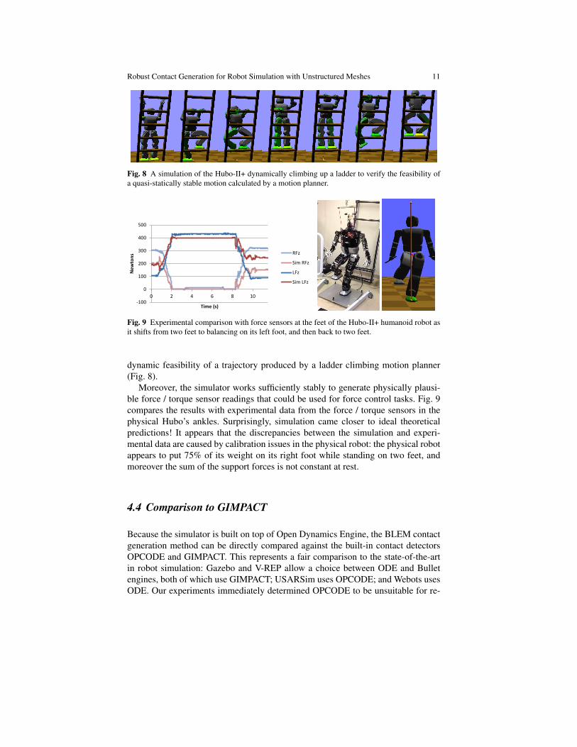
Fig. 8 A simulation of the Hubo-II+ dynamically climbing up a ladder to verify the feasibility ofa quasi-statically stable motion calculated by a motion planner.
-100
0
100
200
300
400
500
0 2 4 6 8 10
New
tons
Time (s)
RFz
Sim RFz
LFz
Sim LFz
Fig. 9 Experimental comparison with force sensors at the feet of the Hubo-II+ humanoid robot asit shifts from two feet to balancing on its left foot, and then back to two feet.
dynamic feasibility of a trajectory produced by a ladder climbing motion planner(Fig. 8).
Moreover, the simulator works sufficiently stably to generate physically plausi-ble force / torque sensor readings that could be used for force control tasks. Fig. 9compares the results with experimental data from the force / torque sensors in thephysical Hubo’s ankles. Surprisingly, simulation came closer to ideal theoreticalpredictions! It appears that the discrepancies between the simulation and experi-mental data are caused by calibration issues in the physical robot: the physical robotappears to put 75% of its weight on its right foot while standing on two feet, andmoreover the sum of the support forces is not constant at rest.
4.4 Comparison to GIMPACT
Because the simulator is built on top of Open Dynamics Engine, the BLEM contactgeneration method can be directly compared against the built-in contact detectorsOPCODE and GIMPACT. This represents a fair comparison to the state-of-the-artin robot simulation: Gazebo and V-REP allow a choice between ODE and Bulletengines, both of which use GIMPACT; USARSim uses OPCODE; and Webots usesODE. Our experiments immediately determined OPCODE to be unsuitable for re-

12 Kris Hauser
0s 5s 10s
15s 20s 25s
0s 5s 10s
15s 16s 18s
GIMPACT
New method
Fig. 10 A model of the Boston Dynamics Atlas humanoid balancing on hands and feet on rough,fractal-generated terrain. Contact forces are depicted as arrows. Using GIMPACT, the robot jittersuntil it begins an unrecoverable fall at 15 s.
alistic simulation because it would quickly “blow up” even on simple examples.GIMPACT is significantly better, and obtains realistic results for many scenarios:coarse meshes that are not-too-concave, and no edgewise contact between triangles.
Fig. 1 illustrates that GIMPACT “blows up” almost instantaneously on a simplecube stacking example where each of the cubes is given by a triangulated mesh. Atthe instant that cube-to-cube contact is made, GIMPACT produces a problematic setof contacts that causes catastrophic failure soon after. By contrast, the new methodstays stable for tens of minutes, and appears to be stable in perpetuity. It has alsobeen tested on a 10 cube stack for 10 minutes with less than a tenth of a millimeterof deviation from the theoretical prediction.1
The example of Fig. 10 shows that even when GIMPACT appears to work fora short while, subtle jitter can accumulate to yield implausible results. The BostonDynamics Atlas robot model from DRCSim v2.2.0 is placed in a stable stance on its
1 ODE provides an option to disable simulation of rigid bodies that are not moving, which improvesthe stability of stacks. Such functionality was not used in these tests.

Robust Contact Generation for Robot Simulation with Unstructured Meshes 13
hands and feet on a rough terrain. The robot attempts to maintain its posture. Usingthe new method, the robot flexes somewhat due to PID control but ultimately staysstably in place. After three minutes of simulation the robot maintained the samepose. Using GIMPACT, the robot stabilizes, but contact handling artifacts period-ically apply impulses that cause the robot to jitter. After approximately 15 s theseimpulses grow sufficiently strong to push the robot off-balance.
The example of Fig. 11 demonstrates that the BLEM approach can handle con-tact between meshes of fine and coarse resolutions, while GIMPACT has problemswith fine-resolution meshes. Here each fingertip of the Willow Garage PR2 gripperis modeled with approximately 1,000 triangles 1 mm2 in size, while the cubes arecoarse, 12-triangle meshes. With BLEMs, the robot lifts the cube, shakes it left andright, and places it back on the table as would be expected. With GIMPACT, thetriangles of the finger mesh simply pass through the cube and the grasp fails.
4.5 Simulating Interaction with Sensed Objects
The next set of examples evaluate the ability to simulate robots interacting withobjects or environments that are partially-modeled by 3D sensors.
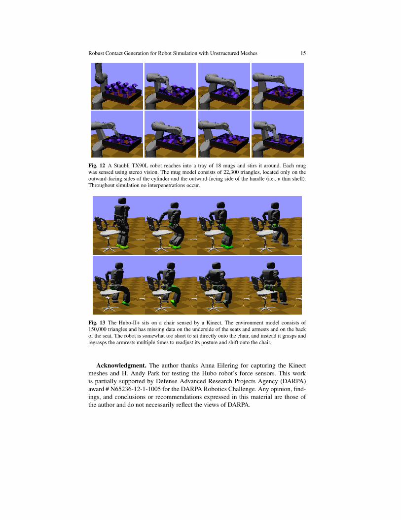
Figure 12 shows an industrial robot interacting with several mugs sensed bystereo vision moving around the mug. The resulting point cloud was segmentedfrom the table and meshed into a thin shell. The model has no volume and no bot-tom. The robot reaches into a tray of several objects and stirs them around. Nointerpenetration between the mugs, robot, or tray occurred during this simulation.The robot can also lift mugs from the handle or from the sides using friction (Fig. 3).
The final examples demonstrate locomotion on static environment meshes cap-tured using the Microsoft Kinect sensor. Figs. 2 and 13 demonstrate the Hubo-II+humanoid climbing with its hands and legs on meshes obtained through the Kinect-Fusion algorithm [12]. These meshes are generated under indoor lighting conditionswith a hand-held Kinect, with no attempt to build a complete model. As a result, theback and lower faces of the ladder and the chair are missing. Although the real chairis a swivel chair, the simulation model is fixed. Because these meshes are extremelylarge — 1 million and 150,000 triangles, respectively — simulation is relativelyslow. For 1 second of simulation, both examples take approximately 1 minutes ofwall clock time, with computation dominated by the contact response step.
5 Conclusion
This paper described a contact generation method that achieves state-of-the-art sta-bility for “out of the box” robot simulation with unstructured triangle meshes. Ex-perimental results demonstrate physically plausible simulations on a variety of ma-

14 Kris Hauser
Fig. 11 A Staubli TX90L robot affixed with the gripper from the Willow Garage PR2 picks upa block, shakes it, and places it down using the new simulator. Contact forces are visualized asarrows. The last frame shows that using GIMPACT, the gripper fingers immediately slip throughthe block and fails to lift the block entirely.
nipulation and locomotion examples, including interactions with noisy, partial 3Dscans of real-world objects.
Interesting future directions might include studying the accuracy/speed tradeoffsof clustering, and developing better clustering methods. For example, contact pointsscattered on a plane can safely be reduced to their convex hull without any loss ofaccuracy in contact response. Another possibility is to incorporate methods for ac-celerating BLEM contact detection with large meshes or point cloud data sets [18],possibly using GPUs. Finally, it may be possible to develop methods that adaptboundary thickness and time stepping dynamically to support collisions betweenvery thin objects, or to employ fallback methods that retract meshes out of collisiononce boundary layers are penetrated.
Robust Contact Generation for Robot Simulation with Unstructured Meshes 15
Fig. 12 A Staubli TX90L robot reaches into a tray of 18 mugs and stirs it around. Each mugwas sensed using stereo vision. The mug model consists of 22,300 triangles, located only on theoutward-facing sides of the cylinder and the outward-facing side of the handle (i.e., a thin shell).Throughout simulation no interpenetrations occur.
Fig. 13 The Hubo-II+ sits on a chair sensed by a Kinect. The environment model consists of150,000 triangles and has missing data on the underside of the seats and armests and on the backof the seat. The robot is somewhat too short to sit directly onto the chair, and instead it grasps andregrasps the armrests multiple times to readjust its posture and shift onto the chair.
Acknowledgment. The author thanks Anna Eilering for capturing the Kinectmeshes and H. Andy Park for testing the Hubo robot’s force sensors. This workis partially supported by Defense Advanced Research Projects Agency (DARPA)award # N65236-12-1-1005 for the DARPA Robotics Challenge. Any opinion, find-ings, and conclusions or recommendations expressed in this material are those ofthe author and do not necessarily reflect the views of DARPA.

16 Kris Hauser
References
1. The blender project. http://www.blender.org/ (accessed Oct 31, 2013)2. Bridson, R., Fedkiw, R., Anderson, J.: Robust treatment of collisions, contact and friction for
cloth animation. In: ACM Transactions on Graphics (Proc. ACM SIGGRAPH) (2002)3. Bullet physics engine. http://bulletphysics.org/ (accessed Oct 31, 2013)4. Carpin, S., Lewis, M., Wang, J., Balakirsky, S., Scrapper, C.: Usarsim: a robot simulator for
research and education. In: IEEE Int. Conf. Rob. Aut., pp. 1400–1405 (2007). DOI 10.1109/ROBOT.2007.363180
5. Coppelia Robotics: Virtual robot experimentation platform (v-rep). http://www.coppeliarobotics.com/ (accessed Oct 31, 2013)
6. Cyberbotics: Webots: the mobile robot simulation software. http://www.cyberbotics.com/ (accessed Oct 31, 2013)
7. Gazebo. http://gazebosim.org/ (accessed Oct 31, 2013)8. Gerkey, B.P., Vaughan, R.T., Howard, A.: The player/stage project: Tools for multi-robot and
distributed sensor systems. In: Proc. 11th International Conference on Advanced Robotics,pp. 317–323 (2003)
9. Gottschalk, S., Lin, M., Manocha, D.: OBB-tree: A hierarchical structure for rapid interferencedetection. In: ACM SIGGRAPH, pp. 171–180 (1996)
10. Guendelman, E., Bridson, R., Fedkiw, R.: Nonconvex rigid bodies with stacking. In: ACMTransactions on Graphics (Proc ACM SIGGRAPH) (2013)
11. Heidelberger, B., Teschner, M., Keiser, R., Muller, M., Gross, M.: Consistent penetration depthestimation for deformable collision response. In: Proc. Vision, Modeling, Visualization, pp.339–346 (2004)
12. Izadi, S., Kim, D., Hilliges, O., Molyneaux, D., Newcombe, R., Kohli, P., Shotton, J., Hodges,S., Freeman, D., Davison, A., Fitzgibbon, A.: Kinectfusion: Real-time 3d reconstruction andinteraction using a moving depth camera. In: ACM Symposium on User Interface Softwareand Technology (2011)
13. Kim, Y., Otaduy, M., Lin, M., Manocha, D.: Fast penetration depth computation forphysically-based animation. In: Symposium on Computer Animation (2002)
14. Lien, J.M., Amato, N.M.: Approximate convex decomposition of polyhedra. In: Proc. of theACM Symposium on Solid and Physical Modeling (SPM). Beijing, China (2007)
15. Mirtich, B.: Impulse-based dynamic simulation of rigid body systems. Ph.D. thesis, Universityof California, Berkeley (1996)
16. Nvidia Corporation: Physx. http://www.nvidia.com/object/nvidia_physx.html (accessed Oct 31, 2013)
17. Open dynamics engine. http://www.ode.org/ (accessed Oct 31, 2013)18. Pan, J., Sucan, I., Chitta, S., Manocha, D.: Real-time collision detection and distance compu-
tation on point cloud sensor data. In: IEEE Int. Conf. Rob. Aut. (2013)19. Redon, S., Kheddar, A., Coquillart, S.: Fast continuous collision detection between rigid bod-
ies. Computer Graphics Forum 21(3), 279–287 (2002)20. Stewart, D., Trinkle, J.: An implicit time-stepping scheme for rigid body dynamics with in-
elastic collisions and coulomb friction. International Journal of Numerical Methods in Engi-neering 39, 2673–2691 (1996)
21. Tang, M., Manocha, D., Otaduy, M.A., Tong, R.F.: Continuous penalty forces. In: ACMTransactions on Graphics (Proc ACM SIGGRAPH) (2012)
22. Usarsim. http://usarsim.sourceforge.net/ (accessed Oct 31, 2013)23. Zhang, L., Kim, Y., Varadhan, G., Manocha, D.: Generalized penetration depth computation.
Computer Aided Design 39(8), 625–638 (2007)24. Zhang, X., Lee, M., Kim, Y.J.: Interactive continuous collision detection for non-convex
polyhedra. Vis. Comput. 22(9), 749–760 (2006). DOI 10.1007/s00371-006-0060-0. URLhttp://dx.doi.org/10.1007/s00371-006-0060-0