Embed Size (px)
Citation preview
Robust Camera Calibration for an Autonomous Underwater Vehicle
Matthew Bryant†, David Wettergreen‡* , Samer Abdallah†, Alexander Zelinsky‡
* Now with The Robotics Institute, Carnegie Mellon University.
Robotic Systems Laboratory†Department of Engineering, FEIT
‡Department of Systems Engineering, RSISEThe Australian National University
Canberra ACT 0200 Australiahttp://wwwsyseng.anu.edu.au/rsl/
Abstract
At the Australian National University we aredeveloping an autonomous underwater vehicle forunderwater exploration and inspection. One of ouraims is to track the relative position of underwatertargets. This has required the development of acamera calibration system that can overcome thedifficulties of underwater vision to provideaccurate camera parameters. Conventional cameracalibration systems detect and then identify pointsin an image of a known 3-D calibration pattern.Point identification algorithms typically require thefull set of calibration points to be detected toregister the target, but this requirement is seldomsatisfied in underwater images. We describe a pointidentification algorithm which does not rely oncomplete point detection, based upon the indexingof planar invariants calculated from points on a 3-Dcalibration pattern. Underwater experiments haveshown our new method improves the likelihood ofsuccessful calibration by up to 80%, and that ourcalibration system calculates camera parametersenabling range estimation of targets up to 3 metresaway with 95% accuracy.
1 IntroductionAt the Australian National University we are developing anautonomous underwater vehicle (AUV) named Kambara.We are researching technologies allowing Kambara tosearch and navigate underwater environments, using visualguidance based on range estimation and feature trackingtechniques.
1.1 Underwater Stereo Camera CalibrationMost range estimation algorithms require knowledge of howpixel coordinates in stereo images correspond to pointcoordinates in 3-D space. Camera parameters define thiscorrespondence, and the procedure of determining theparameters is known as camera calibration.
Camera calibration has been an area of extensiveresearch. Calibration algorithms vary across differentapplications, but most involve processing images of a
FIGURE 1: Kambara’s camera suite
calibration pattern. The camera parameters are calculatedfrom information extracted from the correspondencebetween points on the pattern, and pixels in the patternimage [Trucco,1998].
Calibration patterns are required to provide a set of 3-Dpoints, with a relative geometry known to an accuracy thatexceeds the required accuracy of the vision system. Atypical calibration pattern consists of one or two planar gridsof rectangles, or boxes, on a contrasting background [Tsai,1987]. Points are extracted from images of the pattern usingedge detection, line fitting, and line intersection techniques.A point identification algorithm is applied so that eachdetected image point can be matched with its correspondingpoint in 3-D space. If all the points on the calibration patternare successfully detected then this requires a simple pointordering algorithm.
Underwater environments present challenges to thereliability and accuracy of calibration algorithms. Edgedetection is challenged by the fact that the contrast inunderwater images reduces with depth [Reynolds, 1998].Edges in some regions of an image may therefore be missed,and consequently not all points in a calibration patternimage can be reliably detected. Simple point orderingalgorithms are therefore impractical in underwaterenvironments.
We have addressed this problem by developing a pointidentification algorithm which does not rely on the full setof points being detected. The algorithm is based on indexingplanar projective invariants calculated from points on thecalibration pattern.
1.2 Kambara’s Vision SystemKambara’s vision hardware is comprised of three cameras,shown in Figure 1, and a digitizer. Stereo vision isaccomplished through two Pulnix wide angle lens cameras(TMC-73M), housed in moveable waterproof containersmounted on the Kambara frame. A Sony pan-tilt-zoomcamera (EVI-D30) is mounted in the upper watertightenclosure, capturing images for Kambara’s user-interface. APXC200 Imagenation framegrabber multiplexes the threecamera signals, delivering image frames to the onboardcomputer.
The following section describes the standard approach tocamera calibration, and the problems posed by underwaterimaging. Section 3 discusses our new approach to the pointidentification problem, and section 4 describes ourexperiments evaluating the robustness of the new approach.Section 5 discusses an experiment testing the underwateraccuracy of our calibration system.
2 Camera Calibration Overview
2.1 Camera ParametersCamera parameters characterise the mathematical modelused to describe a camera. Tsai’s camera model [Tsai,1987] uses two parameter categories:
• extrinsic parameters define the position andorientation of the camera relative to a worldreference frame;
• intrinsic parameters define the internal projectivegeometry of the camera, including focal length andlens distortion.
Appendix A lists and explains these parameters.
2.2 Calibration AlgorithmMost camera calibration algorithms use a calibration patternto accurately locate points in space [Trucco, 1998 and thereferences therein]. These 3-D point coordinates arematched with their corresponding image pixel coordinatesas the basis for an algorithm which calculates the cameraparameters.
A typical calibration pattern uses two planar grids ofboxes on a contrasting background [Tsai, 1987], such as theone shown in Figure 2. Algorithm 1 lists the standardalgorithm, used with planar box-grid calibration patterns, forfinding the parameters of a single camera. The extrinsicparameters of each camera can then be used to derive thestereo extrinsic parameters of the camera suite.
1) Capture an image of the calibration pattern2) Detect points:
a) Detect edgesb) Find box edgesc) Fit lines to each box edged) Intersect lines to find corner points
3) Identify points4) Calculate parameters
ALGORITHM 1: A standard camera calibration algorithm.
The performance of a calibration algorithm is judged bythe accuracy of the camera parameters determined in theparameter calculation step, and the reliability of successfulcalibration. Both performance characteristics are dependent
on the quality of the captured image.
2.3 Point DetectionUnderwater environments tend to cause errors in edgedetection, which propagate through to errors in pointdetection.
Edge detection locates pixels in regions where the imageintensity undergoes sharp variations [Trucco, 1998].Underwater environments compromise the detection ofintensity variations, because the scattering of light bysuspended underwater particles decreases image contrast[Reynolds, 1998]. Consequently edges, and therefore cornerpoints, may not be detected in some regions of an image.
The light scattering effect also tends to blur images[Reynolds, 1998], reducing the sharpness in detectedvariations. This makes it difficult for edge detectionalgorithms to locate edges accurately. Lines fitted toinaccurately located edges will deviate from the true boxedge, leading to inaccurately located corner points.
2.4 Point IdentificationPoint identification is the task of identifying each detectedpoint in a projected image of the calibration pattern. If allthe corner points are detected, as is the case in typicalcalibration environments, then simple point sortingalgorithms can be devised to identify the points on the basisof their vertical and horizontal ordering.
In underwater applications the detection of all pointscannot be relied upon, and different techniques must bedevised. These are challenged by the fact that much of thegeometric information relating the points is lost underprojection. In particular, the relative distance betweenpoints, the area of a box, and parallelism are not preservedunder projective transformations [Mundy and Zisserman,1992]. We have addressed the problem with anidentification scheme based on the indexing of planarprojective invariants.
3 Point Identification using InvariantIndexing
We propose a scheme using an index of planar projectiveinvariants to identify boxes in images of a calibrationpattern. The identified boxes can then be used to identifythe box corner points.
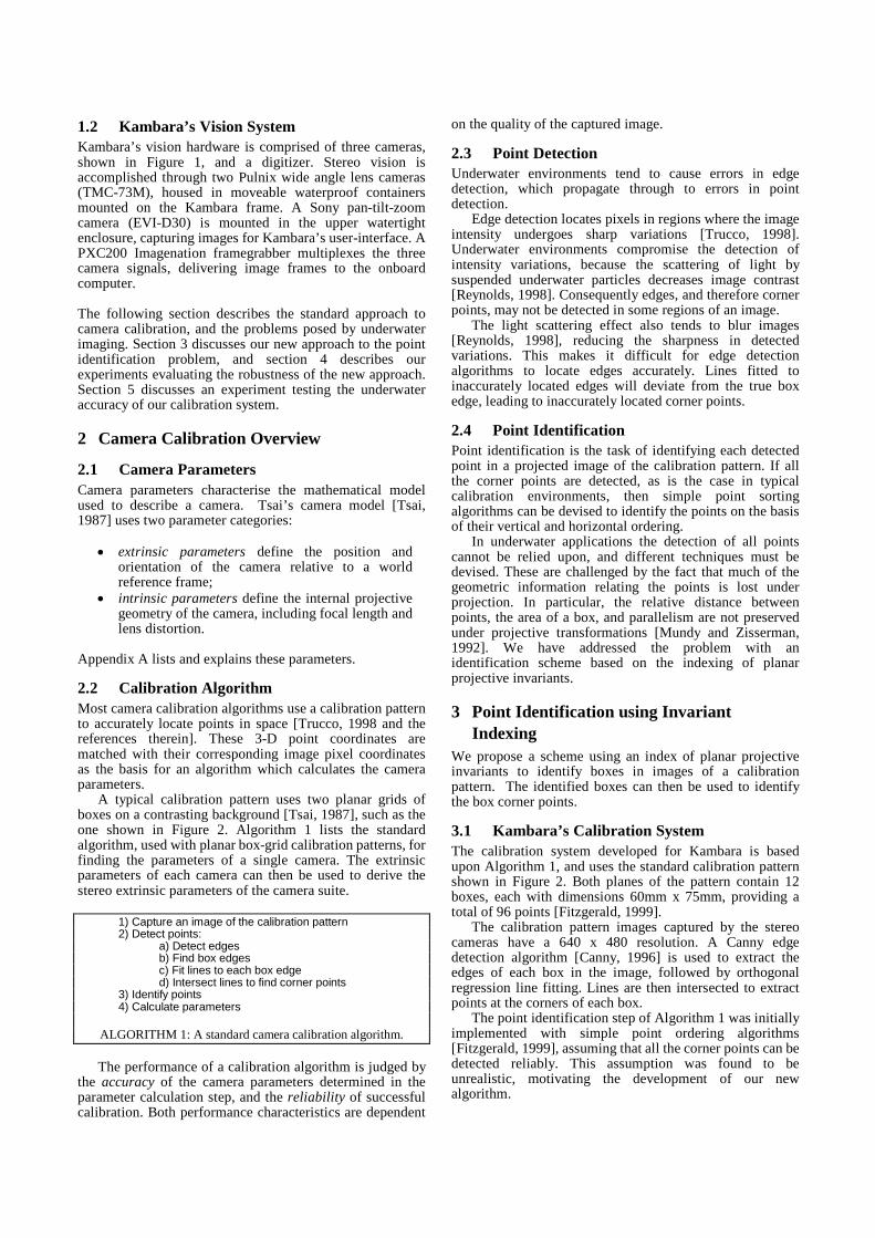
3.1 Kambara’s Calibration SystemThe calibration system developed for Kambara is basedupon Algorithm 1, and uses the standard calibration patternshown in Figure 2. Both planes of the pattern contain 12boxes, each with dimensions 60mm x 75mm, providing atotal of 96 points [Fitzgerald, 1999].
The calibration pattern images captured by the stereocameras have a 640 x 480 resolution. A Canny edgedetection algorithm [Canny, 1996] is used to extract theedges of each box in the image, followed by orthogonalregression line fitting. Lines are then intersected to extractpoints at the corners of each box.
The point identification step of Algorithm 1 was initiallyimplemented with simple point ordering algorithms[Fitzgerald, 1999], assuming that all the corner points can bedetected reliably. This assumption was found to beunrealistic, motivating the development of our newalgorithm.
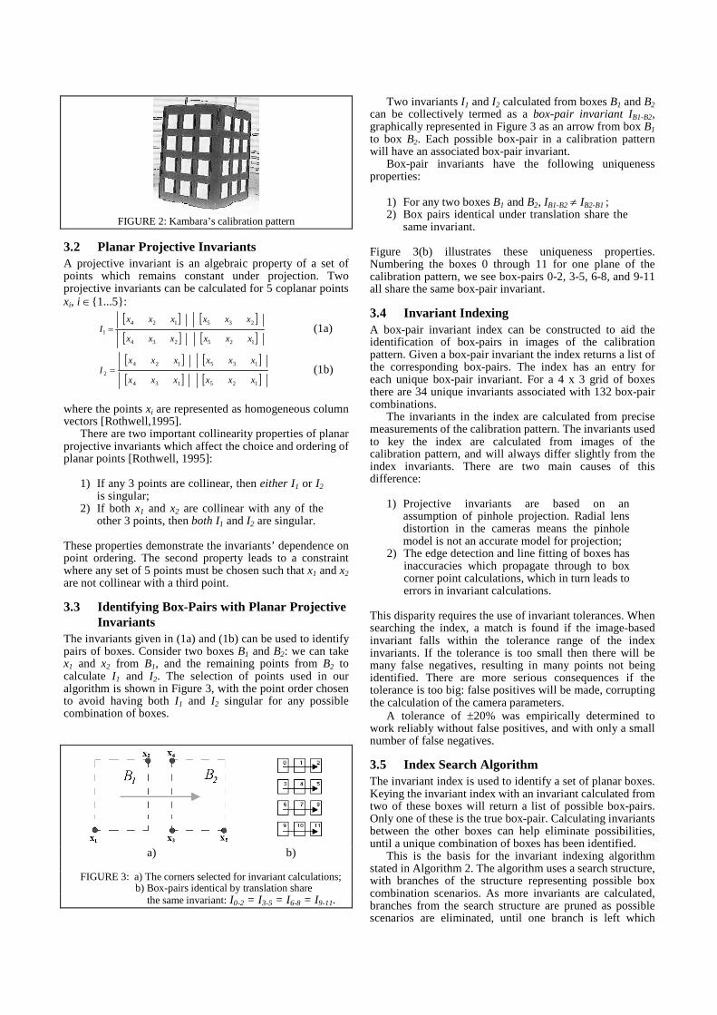
FIGURE 2: Kambara’s calibration pattern
3.2 Planar Projective InvariantsA projective invariant is an algebraic property of a set ofpoints which remains constant under projection. Twoprojective invariants can be calculated for 5 coplanar pointsxi, i ∈{1...5}:
[ ] [ ][ ] [ ]125234
235124
1xxxxxx
xxxxxxI = (1a)
[ ] [ ][ ] [ ]125134
135124
2xxxxxx
xxxxxxI = (1b)
where the points xi are represented as homogeneous columnvectors [Rothwell,1995].
There are two important collinearity properties of planarprojective invariants which affect the choice and ordering ofplanar points [Rothwell, 1995]:
1) If any 3 points are collinear, then either I1 or I2
is singular;2) If both x1 and x2 are collinear with any of the
other 3 points, then both I1 and I2 are singular.
These properties demonstrate the invariants’ dependence onpoint ordering. The second property leads to a constraintwhere any set of 5 points must be chosen such that x1 and x2
are not collinear with a third point.
3.3 Identifying Box-Pairs with Planar ProjectiveInvariants
The invariants given in (1a) and (1b) can be used to identifypairs of boxes. Consider two boxes B1 and B2: we can takex1 and x2 from B1, and the remaining points from B2 tocalculate I1 and I2. The selection of points used in ouralgorithm is shown in Figure 3, with the point order chosento avoid having both I1 and I2 singular for any possiblecombination of boxes.
a) b)
FIGURE 3: a) The corners selected for invariant calculations;b) Box-pairs identical by translation share
the same invariant: I0-2 = I3-5 = I6-8 = I9-11.
Two invariants I1 and I2 calculated from boxes B1 and B2can be collectively termed as a box-pair invariant IB1-B2,graphically represented in Figure 3 as an arrow from box B1
to box B2. Each possible box-pair in a calibration patternwill have an associated box-pair invariant.
Box-pair invariants have the following uniquenessproperties:
1) For any two boxes B1 and B2, IB1-B2 ≠ IB2-B1 ;2) Box pairs identical under translation share the
same invariant.
Figure 3(b) illustrates these uniqueness properties.Numbering the boxes 0 through 11 for one plane of thecalibration pattern, we see box-pairs 0-2, 3-5, 6-8, and 9-11all share the same box-pair invariant.
3.4 Invariant IndexingA box-pair invariant index can be constructed to aid theidentification of box-pairs in images of the calibrationpattern. Given a box-pair invariant the index returns a list ofthe corresponding box-pairs. The index has an entry foreach unique box-pair invariant. For a 4 x 3 grid of boxesthere are 34 unique invariants associated with 132 box-paircombinations.
The invariants in the index are calculated from precisemeasurements of the calibration pattern. The invariants usedto key the index are calculated from images of thecalibration pattern, and will always differ slightly from theindex invariants. There are two main causes of thisdifference:
1) Projective invariants are based on anassumption of pinhole projection. Radial lensdistortion in the cameras means the pinholemodel is not an accurate model for projection;
2) The edge detection and line fitting of boxes hasinaccuracies which propagate through to boxcorner point calculations, which in turn leads toerrors in invariant calculations.
This disparity requires the use of invariant tolerances. Whensearching the index, a match is found if the image-basedinvariant falls within the tolerance range of the indexinvariants. If the tolerance is too small then there will bemany false negatives, resulting in many points not beingidentified. There are more serious consequences if thetolerance is too big: false positives will be made, corruptingthe calculation of the camera parameters.
A tolerance of ±20% was empirically determined towork reliably without false positives, and with only a smallnumber of false negatives.
3.5 Index Search AlgorithmThe invariant index is used to identify a set of planar boxes.Keying the invariant index with an invariant calculated fromtwo of these boxes will return a list of possible box-pairs.Only one of these is the true box-pair. Calculating invariantsbetween the other boxes can help eliminate possibilities,until a unique combination of boxes has been identified.
This is the basis for the invariant indexing algorithmstated in Algorithm 2. The algorithm uses a search structure,with branches of the structure representing possible boxcombination scenarios. As more invariants are calculated,branches from the search structure are pruned as possiblescenarios are eliminated, until one branch is left which

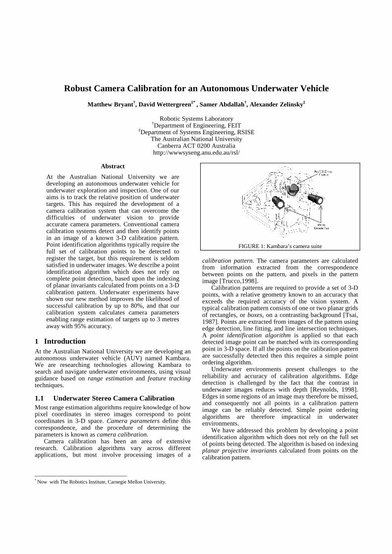
identifies the boxes.The index searching algorithm is illustrated in Figure 5.
In this example only 4 boxes have been detected from aplanar grid: B1, B2, B3, and B4. The box-pair invariant IB1-B2between boxes B1 and B2 is calculated and used to search theinvariant index. A match is found, finding B1 and B2 to beone of 3 possible box-pairs. A search structure is created byallocating a branch to represent each of the 3 scenarios: i) B1
is 3, ii) B1 is 6, and iii) B1 is 9.
1) Begin with a list of n unidentified boxes, B1, B2....Bn
2) Calculate the invariant IB1-B2 from B1 to B2.
3) Key the invariant index with IB1-B2 to find thecorresponding list of box-pairs.
4) Create a search structure with one branch allocatedto each of the box pairs found from the index.
5) For the remaining boxes Bi, i ∈ {3...n}:
a) Calculate the invariant IB1-Bi
b) Use IB1-Bi to look up the invariant indexc) For each box-pair BPj, j ∈ {1...k}, found in the index:
i) Search the structure for a branchhaving the same base box as BPj.
ii) If such a branch is found, then add BPj to it
d) Prune any branch which doesn't have a base boxcorresponding to any of the box-pairs.
6) Succeed if only 1 branch remains inthe search structure, otherwise the boxes B1.....Bn
are insufficient for identification.
ALGORITHM 2: Identifying boxes using a searchstructure and an invariant index.
Next the invariant IB1-B3 between boxes B1 and B3 iscalculated. Searching the invariant index finds that B1 andB3 could be one of 6 possible box-pairs. Only two of themshare the same base boxes with branches of the search tree,namely box-pairs 6-0 and 9-3. These are added to thecorresponding branches. No possible box-pairs are foundconsistent with scenario i), so it is pruned.
Next the invariant IB1-B4 between boxes B1 and B4 iscalculated. Searching the invariant index finds that B1 andB4 could be one of 6 possible box-pairs. Only 1 box-pairshares the same base box with a branch in the search tree,namely 6-10, and this is added to the corresponding branch.None of the box-pairs are found to be consistent withscenario iii), so this branch is pruned.
Only one branch remains, revealing the true identity ofthe boxes: B1 is 6, B2 is 5, B3 is 0, and B4 is 10.
3.6 Performance LimitationsA requirement that must be satisfied for the invariantalgorithm to work is that at least one box from each outerboundary of the planar grid must be detected. The numberof detected boxes required for identification is thereforedependent on which boxes are detected. A box on twoopposite grid corners is sufficient for identification, sinceeach corner box shares two boundaries. The maximumnumber of boxes required in a 4 x 3 grid is 10.
Radial distortion prevents the target being placed tooclose to the cameras, as the true invariants increasinglydeviate from the pin-hole model invariants. This conflictswith the aim of accurately characterising radial distortion,because the more distortion captured by the image points the
better the accuracy of that parameter estimate.Fortunately this is not a serious problem underwater,
since the air-water interface refracts light so as to reducelens distortion. With Kambara's vision system it was foundthe calibration pattern can be brought close enough tooccupy most of the vertical field of view (FOV) of eachcamera.
FIGURE 5: An example illustrating Algorithm 2. Boxes B1, B2, B3
and B4 have been detected in the image of a calibration pattern, buttheir identity is unknown. The invariant index is used together withthe search tree to identify the boxes. The search tree containsbranches representing different possible identities. Arrowsrepresent box-pair invariants, while a cross represents a prunedbranch of the search structure.
4 Calibration Robustness EvaluationThe performance of the calibration system is judged on boththe reliability of the system and the accuracy of thecalculated camera parameters. This section describes theexperimental evaluation of our calibration system’sreliability.

4.1 Experimental ProcedureThe performance of the invariant algorithm was tested bycomparing the reliability of Kambara's calibration systemusing a) the invariant indexing algorithm, and b) simplepoint ordering algorithms reliant on all 96 corner pointsbeing detected.
Calibration testing used underwater stereo image sets ofthe calibration pattern. The image sets were collected byplacing Kambara underwater, and capturing images fromthe stereo cameras as the calibration pattern was movedabout the stereo FOV. The stereo camera pair, apart frombeing slightly verged to enable a close stereo range, werearbitrarily oriented. The calibration pattern was oriented soas to be approximately horizontal in the FOV of eachcamera.
Not all the captured image sets were fit for calibration.Image sets were discarded if a) both planes of thecalibration pattern was not seen clearly in the FOV of bothcameras; or b) the calibration pattern was more than 2metres away from the cameras — if the calibration pattern isfurther away than this, then each projected box edge has toofew pixels for accurate line fitting.
A total of 43 image sets satisfying these requirementswere used for testing our calibration technique. Each imageset was used twice for calibration, once each for the pointordering and invariant indexing algorithms.
4.2 ResultsWe found the invariant indexing algorithm to be far superiorthan simple point ordering. The results of comparison aresummarised in Table 1.
Although the point ordering algorithm led to thesuccessful calibration of one of the stereo cameras for 40%of the image sets, calibration of both cameras neveroccurred. This result emphasises the difficulty of detectingall 96 corner points in an underwater environment.
The invariant indexing algorithm led to the successfulcalibration of both cameras for 80% of the image sets.
PointIdentification
Algorithm
% of images sets forwhich at least 1
camera calibratedsuccessfully
% of images sets forwhich BOTH
cameras’ calibratedsuccessfully
Point ordering 40% 0%
Invariant indexing 81% 80%
TABLE 1: Evaluation of calibration system reliability with pointordering and invariant indexing point identification algorithms.
5 Calibration Accuracy EvaluationUnderwater environments present challenges to theaccuracy of point detection, and consequently the accuracyof camera calibration. This section discusses the challengesof evaluating calibration accuracy, and outlines amethodology which evaluates accuracy using 3-D objectdimension estimation.
5.1 Difficulties in Parameter AccuracyEvaluation
Evaluation of the calibration system accuracy is challengingbecause of the difficulty in obtaining ground truth for
comparison.A camera’s intrinsic parameters are dependent on many
factors, including the calibration environment, so it isimpossible for a camera manufacturer to providecomprehensive parameter specifications.
A camera’s extrinsic parameters can in principle becompared with measurements made between camera andworld reference frames. In practice, however, suchmeasurements are inaccurate and therefore inappropriate forcomparison, since a) the origin of the camera referenceframe is located within the camera, and thereforeinaccessible to ‘ruler’ measurements, and b) it is impossibleto accurately locate the origin of a camera reference frame.
Another approach might be to use the accuracy of rangeestimation to infer the accuracy of the camera parameters.Range estimation estimates the vector from a camerareference frame to a point in 3-D space. Unfortunatelyinaccessibility of the camera reference frame again preventsmeaningful comparison with measured distances.
5.2 Experimental MethodologyWe have devised an experimental approach which comparesthe estimated length of objects in Kambara’s environmentwith accurate ruler measurements. The length estimates arefound by firstly using range estimation to determine therange vectors to two points in space, and then using simplevector arithmetic to find the distance between the twopoints. If length estimates are accurate then it can beinferred that range vectors are accurate, which in turn infersthat the calculated camera parameters are accurate.
The range estimation algorithm used for this experimentis listed in Appendix B.
5.3 Experimental ProcedureKambara was placed underwater together with thecalibration pattern, and the stereo cameras were calibrated.
The calibration pattern was then used to provide pairs ofpoints separated by precisely known distances. Estimates ofpoint-pair displacements were taken with the calibrationpattern approximately 1, 2 and 3 metres away fromKambara. At each of these distances the pattern was movedabout the FOV of each camera, and at each position roughly8 distance measurements between point pairs werecalculated.
5.4 ResultsThe accuracy of length estimation at each distance wascalculated as a percentage error of the true (measured)length. The average and maximum percentage errors foreach distance are listed in Table 2.
Length estimates were found to have a maximum meanerror of 5%, indicating that the calculated cameraparameters are sufficiently accurate for range estimation oftargets up to 3 metres away. It was also found that rangeestimates improve as the target approaches closer to theAUV, which is consistent with our intuition that small errorsin a range vector's orientation will amplify with distance.
Approximate distancebetween AUV and target
MeanError %
Std Dev%
Max Error%
1 metre 1.4 % 1% 6%2 metre 3.6 % 2.7% 15%3 metre 5.0 % 5.2% 30%
TABLE 2: Evaluation of calibration system accuracy
6 ConclusionWe have developed a new point identification algorithm,based on planar projective invariant indexing. Experimentalevaluation has shown the algorithm to be up to 80% morereliable than simple point ordering algorithms. Furtherexperiments have found Kambara's calibration system,based on our invariant indexing algorithm, to be sufficientlyaccurate for range estimation applications with targetdistances up to 3 metres.
There is scope for improvement in the reliability ofunderwater calibration. Finding an optimum invarianttolerancing scheme would help reduce index false negatives,and therefore increase the calibration success rate.Robustness could be further enhanced by developingtechniques allowing the calibration pattern to be held atarbitrary orientations with respect to the camera suite.
In conclusion, we believe that we have developed andtested a camera calibration scheme suitable for underwatercomputer vision applications.
AcknowledgmentsWe wish to thank all current and past members of theKambara team for their tireless support and encouragement.We are especially grateful to Ian Fitzgerald for developingthe original Kambara calibration system.
A Camera ParametersThe intrinsic parameters of a camera consist of:
• f - focal length of the camera;• K1 - radial lens distortion coefficient;• (Cx , Cy ) - pixel coordinates of the centre of lens
distortion;• sx - horizontal scale factor;• (dx , dy)- the "centre-to-centre" distance between
adjacent CCD sensor elements in the X and Ydirections;
• Ncx - the number of CCD sensors in the X direction;• Nfx - the number of pixels sampled in the X direction.
The stereo extrinsic parameters define the mappingbetween the camera reference frames of the left and rightcameras (denoted {L} and {R}). They consist of a translation
vector [ ] T
zLRy
LRx
LRR
L pppP = and rotation matrix RLR .
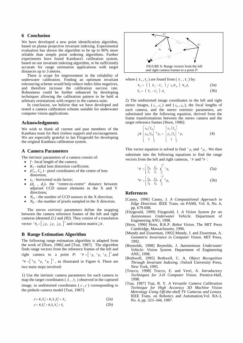
B Range Estimation AlgorithmThe following range estimation algorithm is adapted fromthe work of [Horn, 1986] and [Tsai, 1987]. The algorithmfinds range vectors from the reference frames of the left andright camera to a point P: [ ] T
zL
yL
xLL pppP = and
[ ] T
zR
yR
xRR pppP = , as illustrated in Figure 6. There are
two main steps involved:
1) Use the intrinsic camera parameters for each camera tomap the target coordinates ( fX , fY ) observed in the captured
image, to undistorted coordinates ( 'x , 'y ) corresponding tothe pinhole camera model [Tsai, 1987]:
dddd XYXKXKx ++= 21
31' (2a)
dddd YXYKYKy ++= 21
31' (2b)
FIGURE 6: Range vectors from the leftand right camera frames to a point P.
where ( dX , dY ) are found from ( fX , fY ) by:
( )( ) xcxfxxxfd dNNsCXX −= (3a)
( ) yyfd dCYY −= (3b)
2) The undistorted image coordinates in the left and rightstereo images, ( '
Lx , 'Ly ) and ( '
Rx , 'Ry ), the focal lengths of
each camera, and the stereo extrinsic parameters, aresubstituted into the following equation, derived from theframe transformations between the stereo camera and thetarget reference frames [Horn, 1996]:
zL
LL
LL
zR
RR
RR
LR pfy
fx
pfy
fx
R
=
11
'
'
'
'
(4)
This vector equation is solved to find zL p and z
R p . We thensubstitute into the following equations to find the rangevectors from the left and right cameras, PL and PR :
zL
T
L
L
L
LL pf
y
f
xP
= 1
''
(5a)
zR
T
R
R
R
RR pf
y
f
xP
= 1
''
(5b)
References[Canny, 1996] Canny, J. A Computational Approach to
Edge Detection. IEEE Trans. on PAMI, Vol. 8, No. 6,pp. 679-698.
[Fitzgerald, 1999] Fitzgerald, I. A Vision System for anAutonomous Underwater Vehicle. Department ofEngineering ANU, 1998.
[Horn, 1996] Horn, B.K.P. Robot Vision. The MIT PressCambridge, Massachusetts, 1996.
[Mundy and Zisserman, 1992] Mundy, J. and Zisserman, A.Geometric Invariance in Computer Vision. MIT Press,1992.
[Reynolds, 1998] Reynolds, J. Autonomous UnderwaterVehicle: Vision System. Department of EngineeringANU, 1998.
[Rothwell, 1995] Rothwell, C. A. Object RecognitionThrough Invariant Indexing. Oxford University Press,New York, 1995.
[Trucco, 1998] Trucco, E. and Verri, A. IntroductoryTechniques for 3-D Computer Vision. Prentice-Hall,1998.
[Tsai, 1987] Tsai, R. Y. A Versatile Camera CalibrationTechnique for High Accuracy 3D Machine VisionMetrology Using Off-the-shelf TV Cameras and Lenses.IEEE Trans. on Robotics and Automation,Vol. RA-3,No. 4, pp. 323–344, 1987.