Embed Size (px)
Citation preview
Actuators in robotics Overview
Václav Hlaváč Czech Technical University in Prague Faculty of Electrical Engineering Department of Cybernetics Czech Republic http://cmp.felk.cvut.cz/~hlavac
Courtesy to several authors of presentations on the web.
2
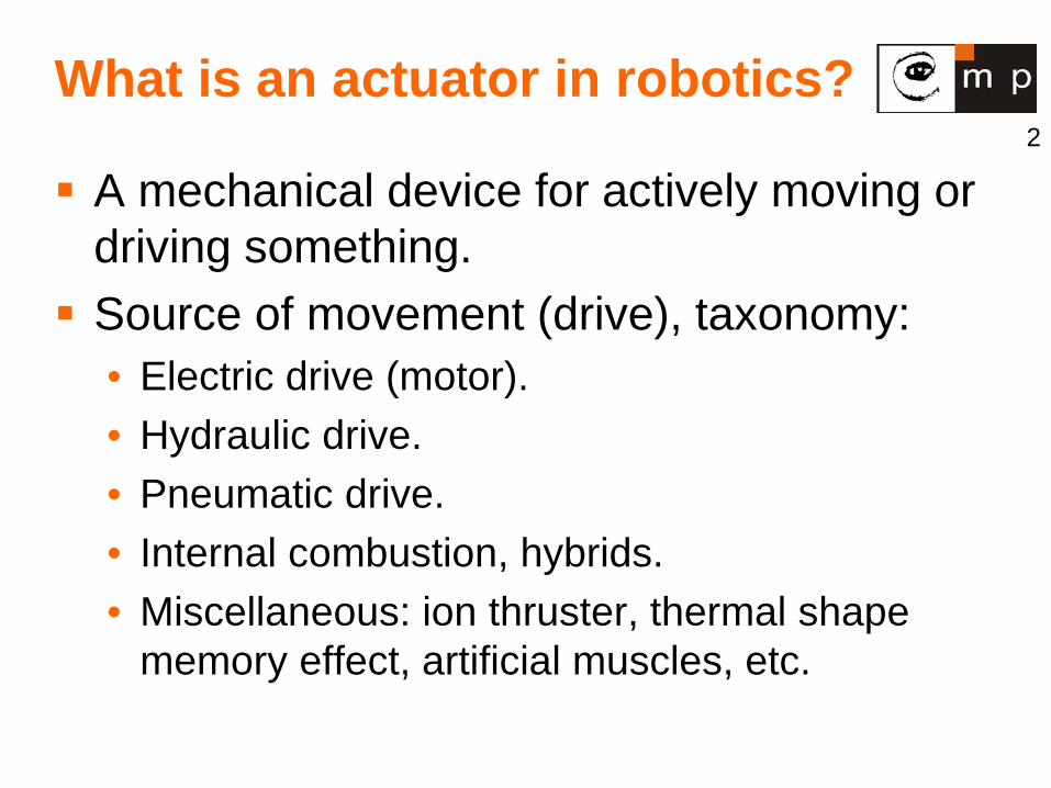
What is an actuator in robotics?
A mechanical device for actively moving or driving something. Source of movement (drive), taxonomy:
• Electric drive (motor). • Hydraulic drive. • Pneumatic drive. • Internal combustion, hybrids. • Miscellaneous: ion thruster, thermal shape
memory effect, artificial muscles, etc.
3
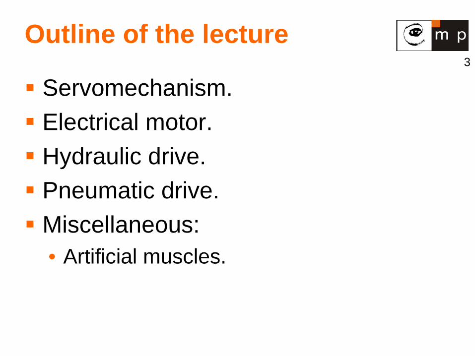
Outline of the lecture
Servomechanism. Electrical motor. Hydraulic drive. Pneumatic drive. Miscellaneous:
• Artificial muscles.
4
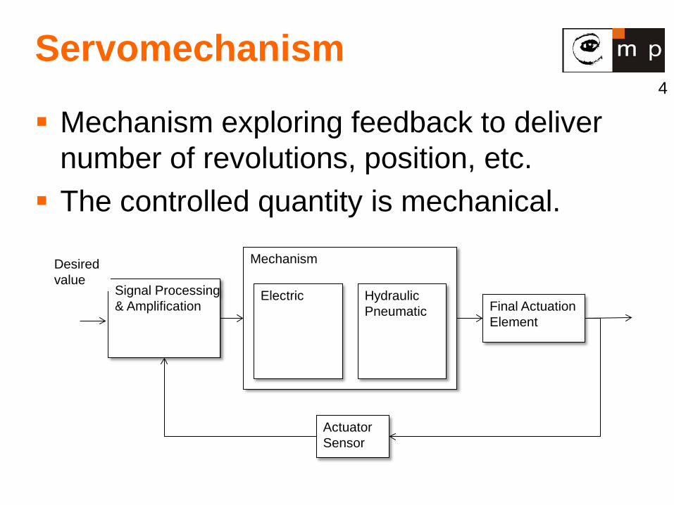
Servomechanism
Mechanism exploring feedback to deliver number of revolutions, position, etc. The controlled quantity is mechanical.
Signal Processing & Amplification
Mechanism
Electric Hydraulic Pneumatic Final Actuation
Element
Actuator Sensor
Desired value
5
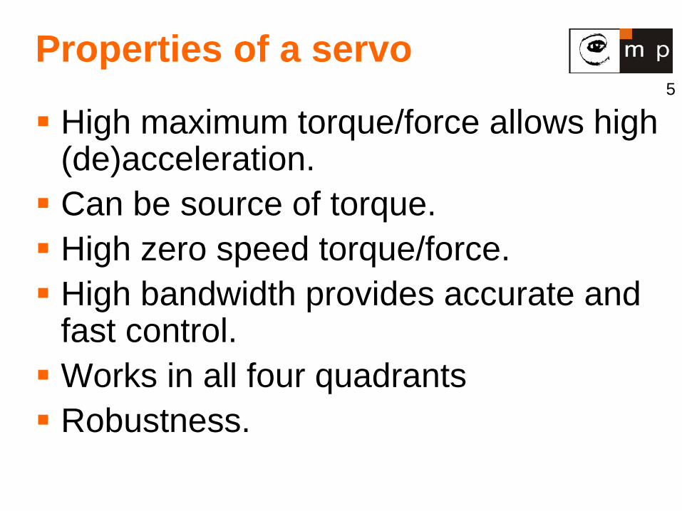
Properties of a servo
High maximum torque/force allows high (de)acceleration. Can be source of torque. High zero speed torque/force. High bandwidth provides accurate and
fast control. Works in all four quadrants Robustness.
7
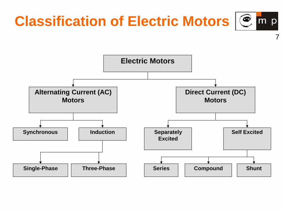
Classification of Electric Motors
Electric Motors
Alternating Current (AC) Motors
Direct Current (DC) Motors
Synchronous Induction
Three-Phase Single-Phase
Self Excited Separately Excited
Series Shunt Compound
8
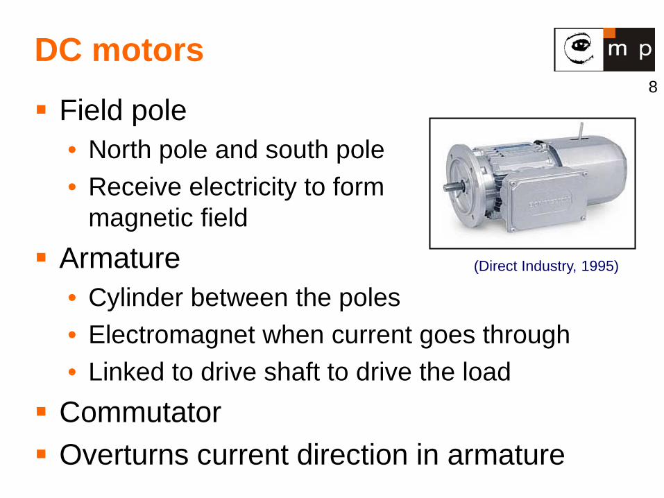
DC motors
Field pole • North pole and south pole • Receive electricity to form
magnetic field Armature
• Cylinder between the poles • Electromagnet when current goes through • Linked to drive shaft to drive the load
Commutator Overturns current direction in armature
(Direct Industry, 1995)
9
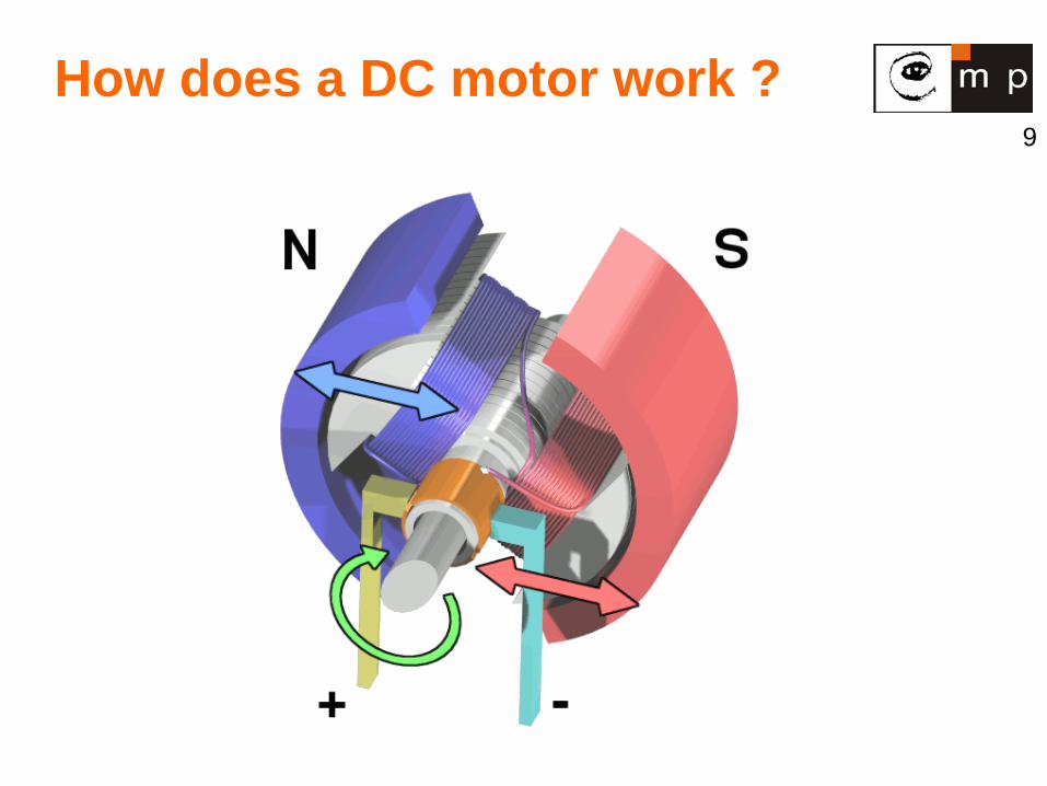
How does a DC motor work ?
10
DC motors, cont.
Speed control without impact power supply quality • Changing armature voltage • Changing field current
Restricted use • Few low/medium speed applications • Clean, non-hazardous areas
Expensive compared to AC motors
11
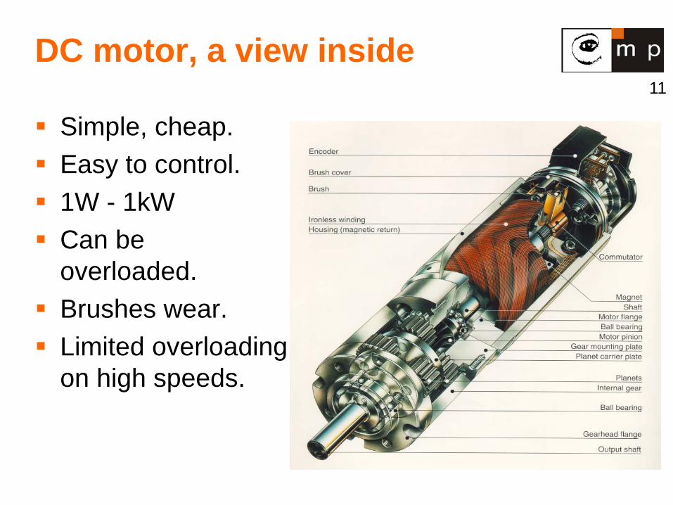
DC motor, a view inside
Simple, cheap. Easy to control. 1W - 1kW Can be
overloaded. Brushes wear. Limited overloading
on high speeds.
12
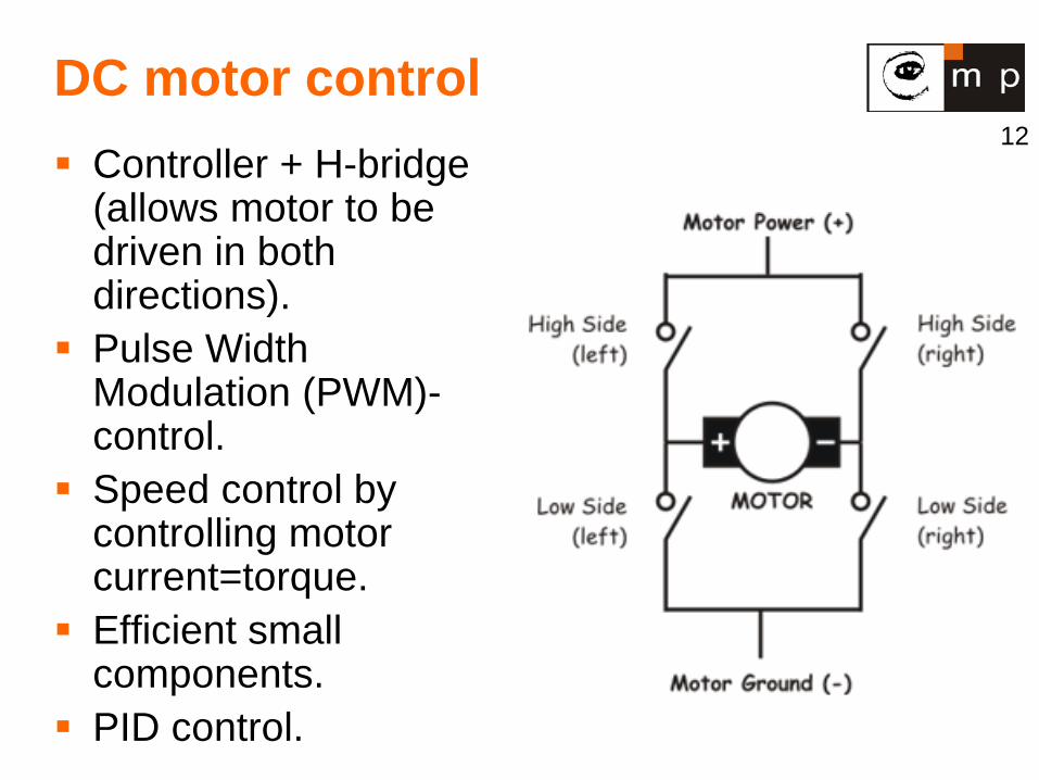
DC motor control Controller + H-bridge
(allows motor to be driven in both directions).
Pulse Width Modulation (PWM)-control.
Speed control by controlling motor current=torque.
Efficient small components.
PID control.
13
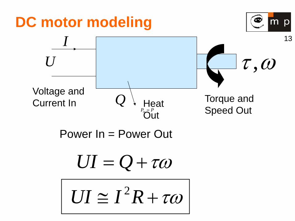
DC motor modeling
PPin =
Voltage and Current In Torque and
Speed Out Heat Out
ωτ ,Q
UI
Power In = Power Out
τω+= QUI
τω+≅ RIUI 2
14
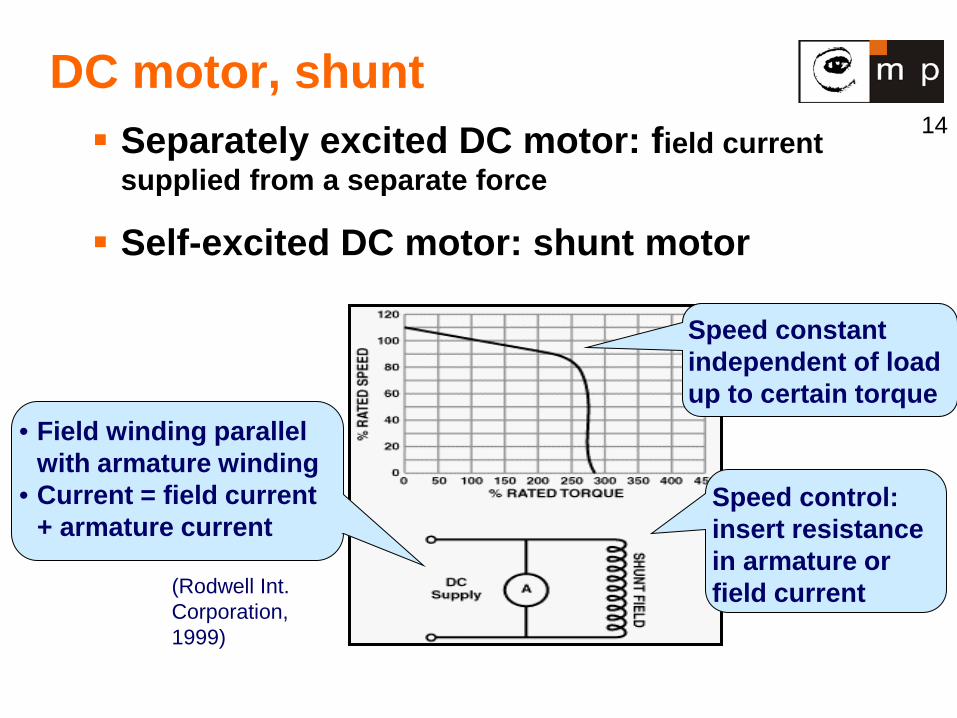
DC motor, shunt Separately excited DC motor: field current
supplied from a separate force
Self-excited DC motor: shunt motor
• Field winding parallel with armature winding
• Current = field current + armature current
Speed constant independent of load up to certain torque
Speed control: insert resistance in armature or field current (Rodwell Int.
Corporation, 1999)
15
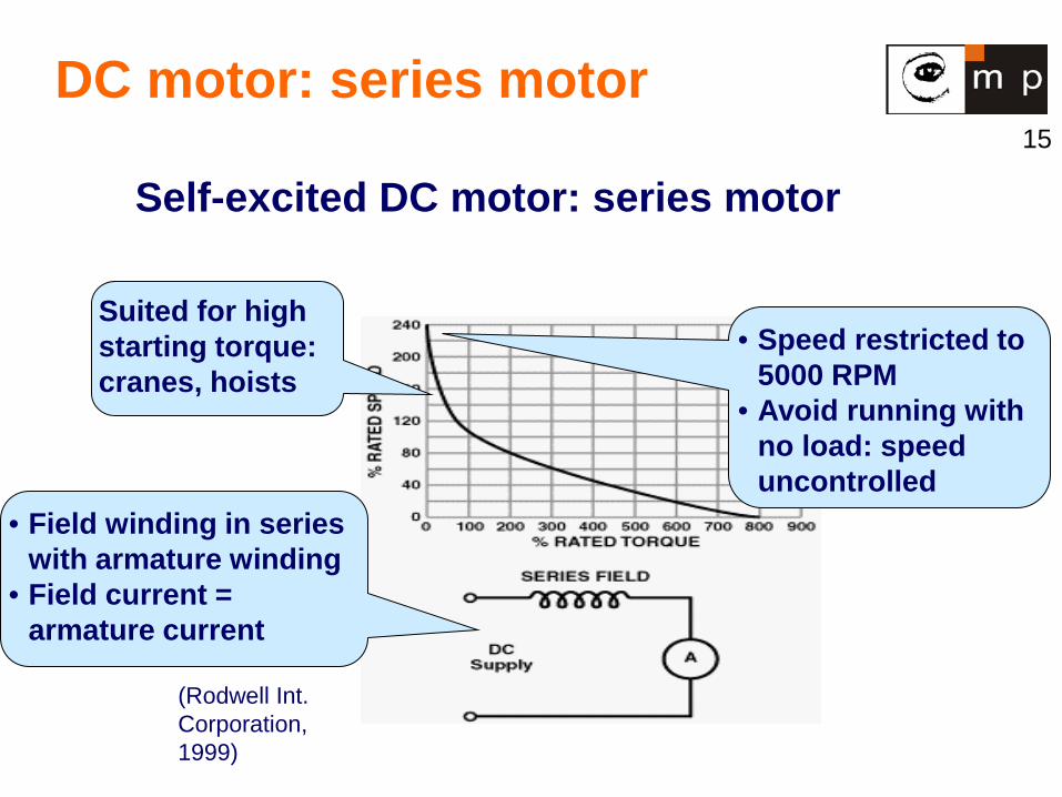
DC motor: series motor
Self-excited DC motor: series motor
(Rodwell Int. Corporation, 1999)
• Field winding in series with armature winding
• Field current = armature current
• Speed restricted to 5000 RPM
• Avoid running with no load: speed uncontrolled
Suited for high starting torque: cranes, hoists
16
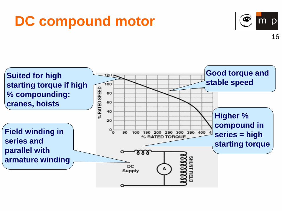
DC compound motor
Field winding in series and parallel with armature winding
Good torque and stable speed
Higher % compound in series = high starting torque
Suited for high starting torque if high % compounding: cranes, hoists
17
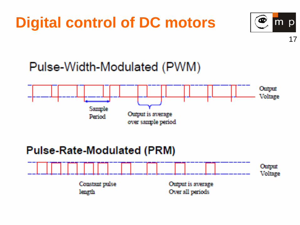
Digital control of DC motors
18
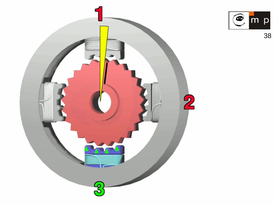
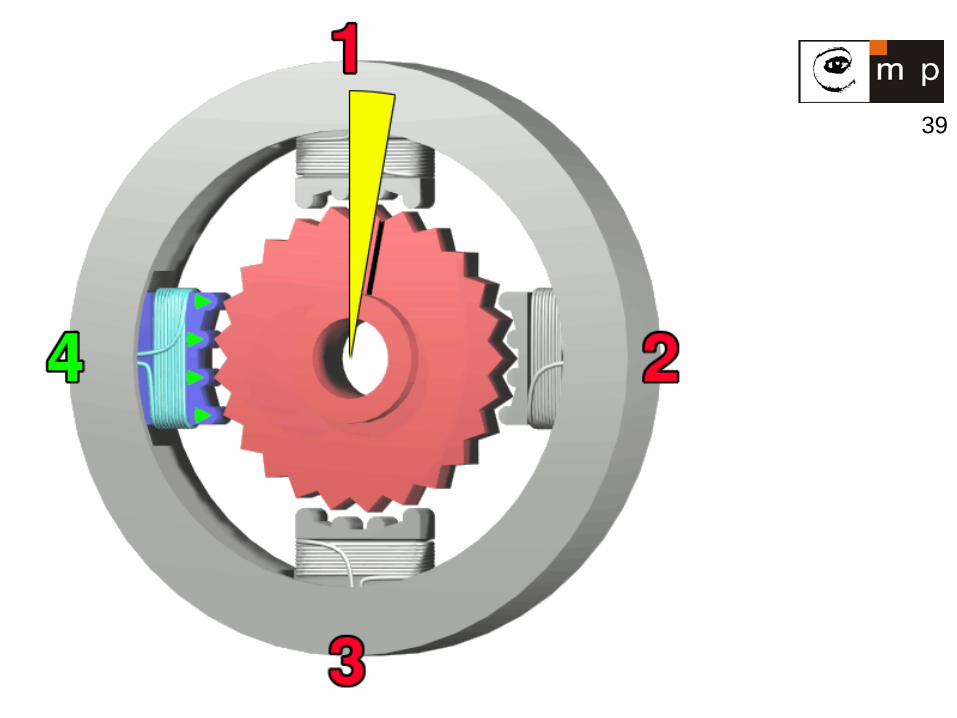
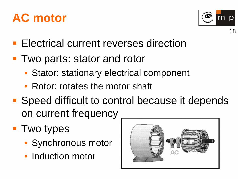
AC motor
Electrical current reverses direction Two parts: stator and rotor
• Stator: stationary electrical component • Rotor: rotates the motor shaft
Speed difficult to control because it depends on current frequency Two types
• Synchronous motor • Induction motor
19
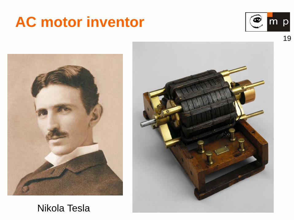
AC motor inventor
Nikola Tesla
20
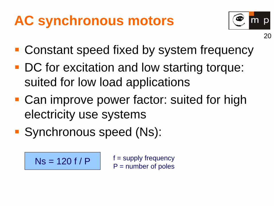
AC synchronous motors
Constant speed fixed by system frequency DC for excitation and low starting torque:
suited for low load applications Can improve power factor: suited for high
electricity use systems Synchronous speed (Ns):
Ns = 120 f / P f = supply frequency P = number of poles
21
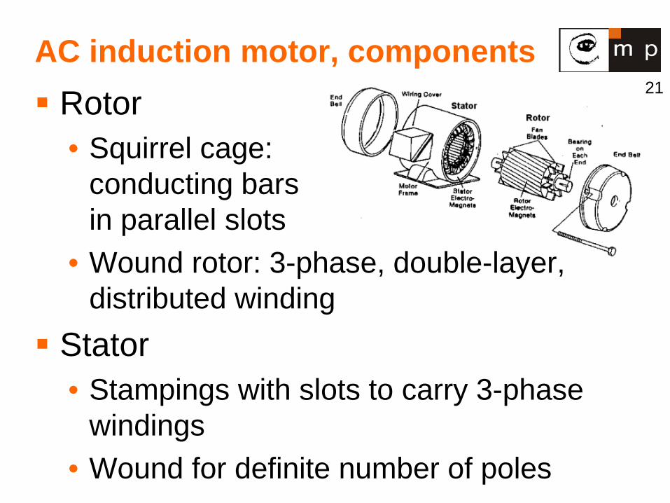
AC induction motor, components Rotor
• Squirrel cage: conducting bars in parallel slots
• Wound rotor: 3-phase, double-layer, distributed winding
Stator • Stampings with slots to carry 3-phase
windings • Wound for definite number of poles

22
How induction motors work ?
Electricity supplied to the stator.
Magnetic field generated that moves around rotor.
Current induced in rotor. Rotor produces second
magnetic field that opposes stator magnetic field.
Rotor begins to rotate.
Electromagnetics
Stator
Rotor
23
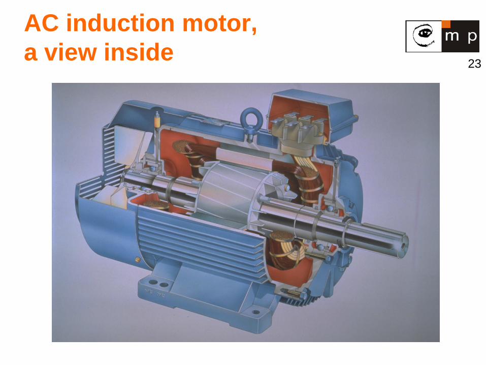
AC induction motor, a view inside
24
AC induction motors, properties
Disadvantages: About 7x overload
current at start. Needs a frequency
changer for control. Advantages: Simple design, cheap Easy to maintain Direct connection to
AC power source
Advantages (cont): Self-starting. 0,5kW ‒ 500kW. High power to weight
ratio High efficiency: 50 –
95 %
25
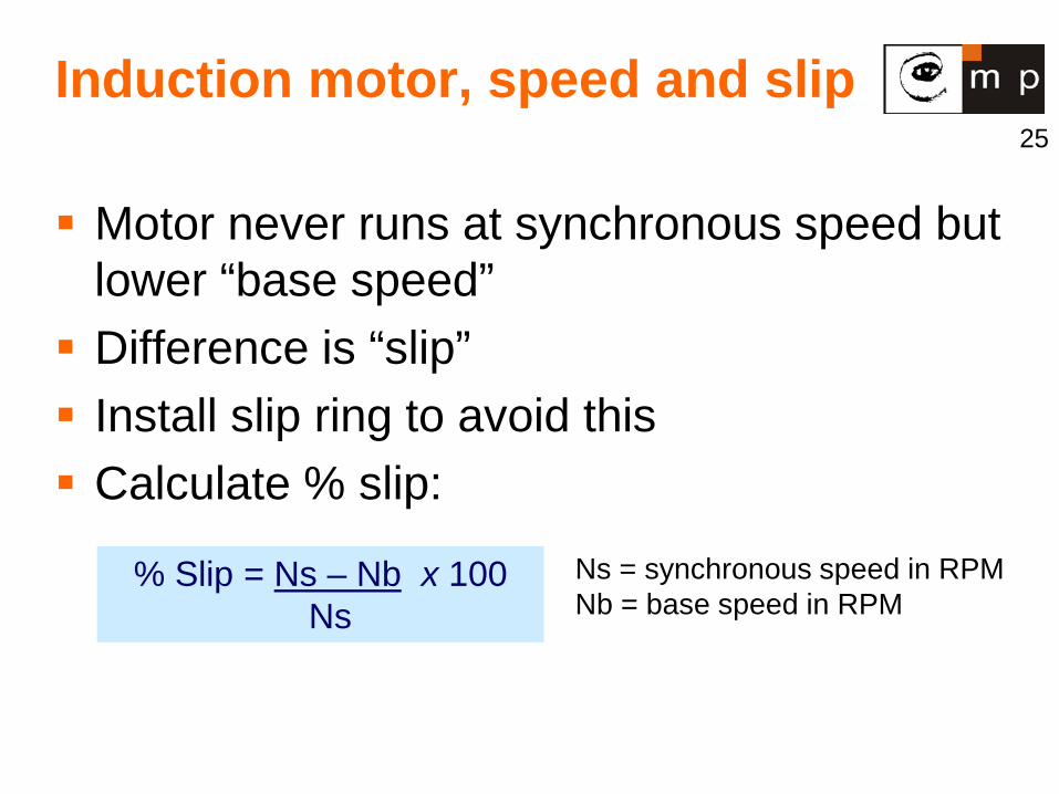
Induction motor, speed and slip
Motor never runs at synchronous speed but lower “base speed” Difference is “slip” Install slip ring to avoid this Calculate % slip:
% Slip = Ns – Nb x 100 Ns
Ns = synchronous speed in RPM Nb = base speed in RPM
26
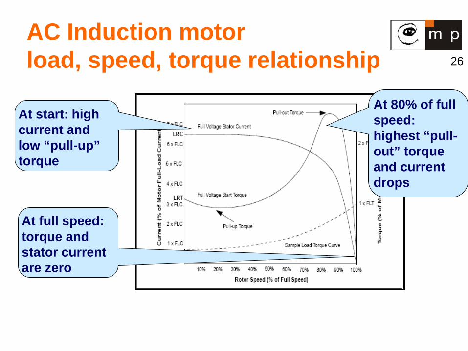
AC Induction motor load, speed, torque relationship
At start: high current and low “pull-up” torque
At 80% of full speed: highest “pull-out” torque and current drops
At full speed: torque and stator current are zero
27
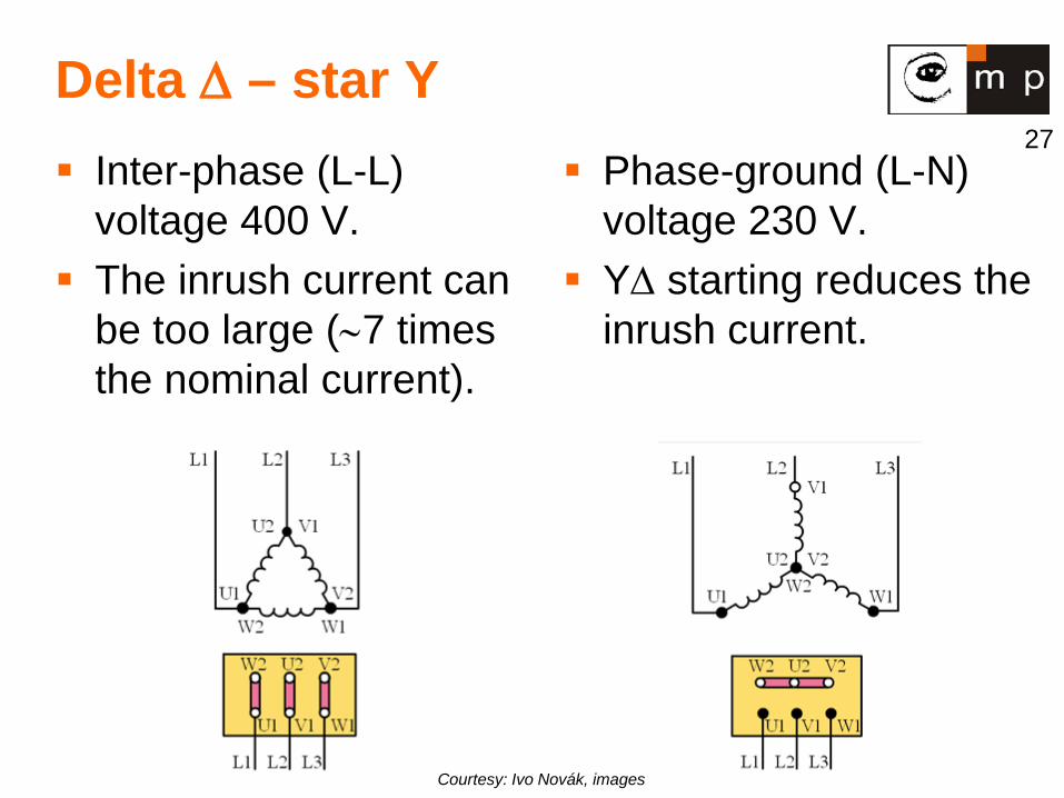
Delta ∆ – star Y Inter-phase (L-L)
voltage 400 V. The inrush current can
be too large (∼7 times the nominal current).
Phase-ground (L-N) voltage 230 V.
Y∆ starting reduces the inrush current.
Courtesy: Ivo Novák, images
28
Single phase induction motor One stator winding. Single-phase power supply. Squirrel cage rotor. Use several tricks to start, then transition to an
induction motor behavior. Up to 3 kW applications. Household appliances: fans, washing
machines, dryers, airconditioners. Lower efficiency: 25 – 60 % Often low starting torque.
29
Single-phase induction motor
Three-phase motors produce a rotating magnetic field. When only single-phase power is available,
the rotating magnetic field must be produced using other means. Two methods to create the rotating magnetic
field are usually used: 1. Shaded-pole motor. 2. Split-phase motor.
30
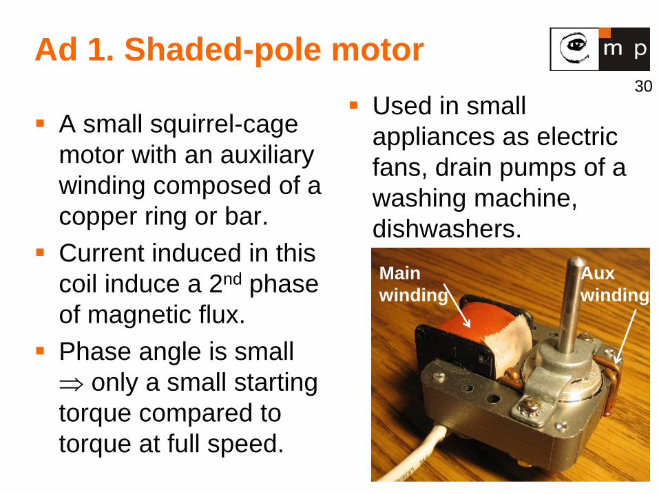
Ad 1. Shaded-pole motor
A small squirrel-cage motor with an auxiliary winding composed of a copper ring or bar.
Current induced in this coil induce a 2nd phase of magnetic flux.
Phase angle is small ⇒ only a small starting torque compared to torque at full speed.
Used in small appliances as electric fans, drain pumps of a washing machine, dishwashers.
Aux winding
Main winding

31
Ad 2. Split-phase motor (1)
Has a startup winding separate from the main winding. Fewer turns of smaller wire than the main winding, so it has a lower inductance (L) and higher resistance (R).
The lower L/R ratio creates a small phase shift, not more than about 30 degrees.
At start, the startup winding is connected to the power source via a centrifugal switch, which is closed at low speed.
The starting direction of rotation is given by the order of the connections of the startup winding relative to the running winding.
32
Ad 2. Split-phase motor (2)
Once the motor reaches near operating speed, the centrifugal switch opens, disconnecting the startup winding from the power source.
The motor then operates solely on the main winding.
The purpose of disconnecting the startup winding is to eliminate the energy loss due to its high resistance.
Commonly used in major appliances such as air conditioners and clothes dryers.
33
Ad 2. Split-phase motor (3)
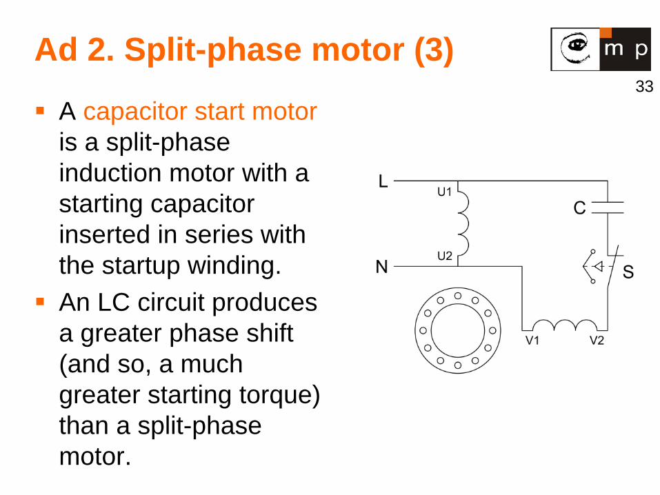
A capacitor start motor is a split-phase induction motor with a starting capacitor inserted in series with the startup winding.
An LC circuit produces a greater phase shift (and so, a much greater starting torque) than a split-phase motor.
34
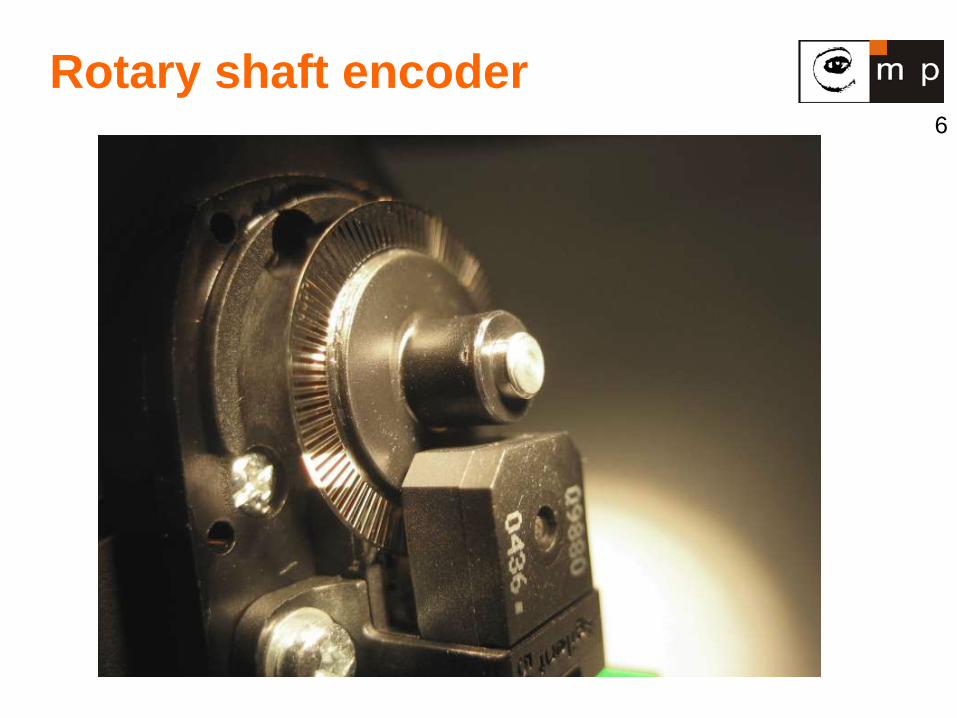
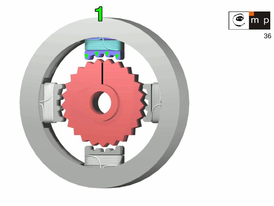
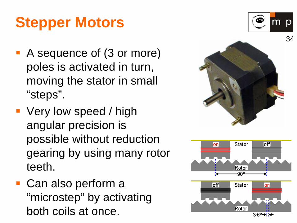
Stepper Motors
A sequence of (3 or more) poles is activated in turn, moving the stator in small “steps”.
Very low speed / high angular precision is possible without reduction gearing by using many rotor teeth.
Can also perform a “microstep” by activating both coils at once.
35
Driving stepper motors
Signals to the stepper motor are binary, on-off values (not PWM).
In principle easy: activate poles as A B C D A … or A D C B A …Steps are fixed size, so no need to sense the angle! (open loop control).
In practice, acceleration and possibly jerk must be bounded, otherwise motor will not keep up and will start missing steps (causing position errors).
Driver electronics must simulate inertia of the motor.
40
Stepper Motor Selection
Permanent Magnet / Variable Reluctance Unipolar vs. Bipolar Number of Stacks Number of Phases Degrees Per Step Microstepping Pull-In/Pull-Out Torque Detent Torque
41
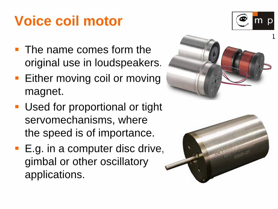
Voice coil motor
The name comes form the original use in loudspeakers.
Either moving coil or moving magnet.
Used for proportional or tight servomechanisms, where the speed is of importance.
E.g. in a computer disc drive, gimbal or other oscillatory applications.
42
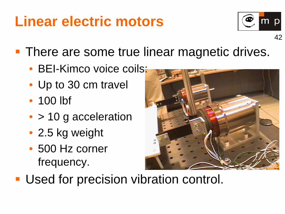
Linear electric motors
There are some true linear magnetic drives. • BEI-Kimco voice coils: • Up to 30 cm travel • 100 lbf • > 10 g acceleration • 2.5 kg weight • 500 Hz corner
frequency. Used for precision vibration control.
43
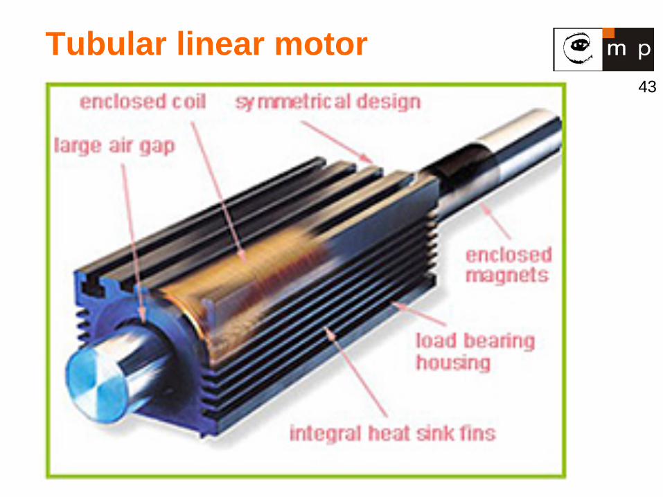
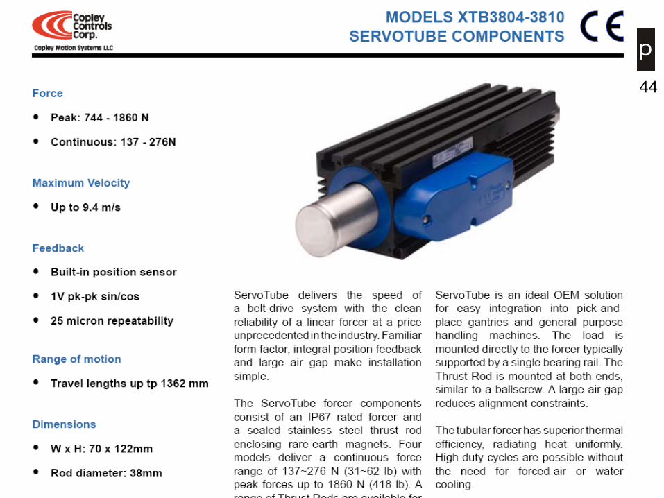
Tubular linear motor
44
45
Courtesy Jussi Suomela
Linear movement. Big forces without gears. Actuators are simple. Used often in mobile machines. Bad efficiency. Motor, pump, actuator combination is lighter
than motor, generator, battery, motor & gear combination.
Hydraulic actuators
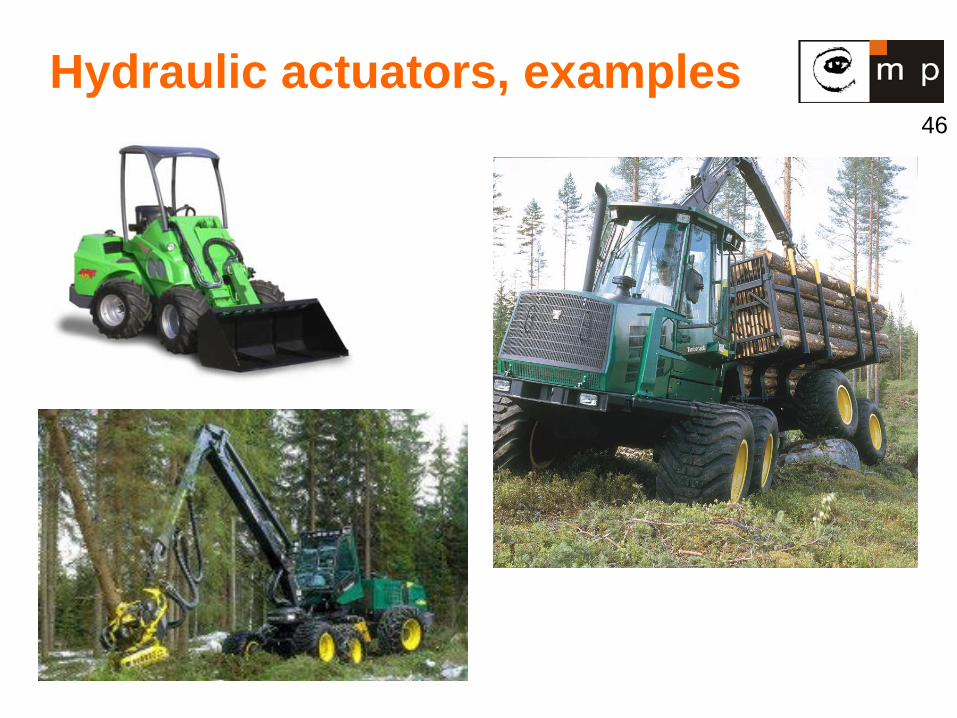
46
Hydraulic actuators, examples
47
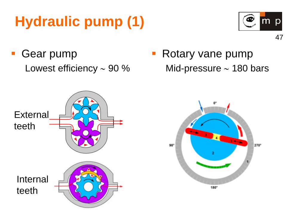
Hydraulic pump (1)
Gear pump Lowest efficiency ∼ 90 %
Rotary vane pump Mid-pressure ∼ 180 bars
External teeth
Internal teeth
48
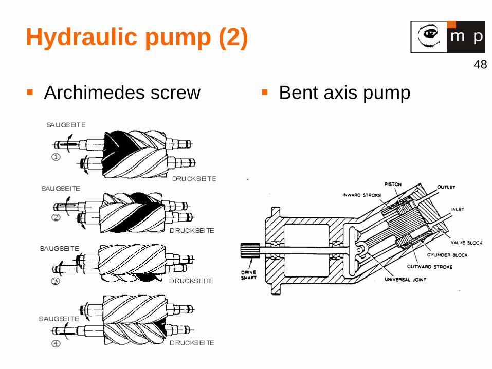
Hydraulic pump (2)
Archimedes screw pump
Bent axis pump
49
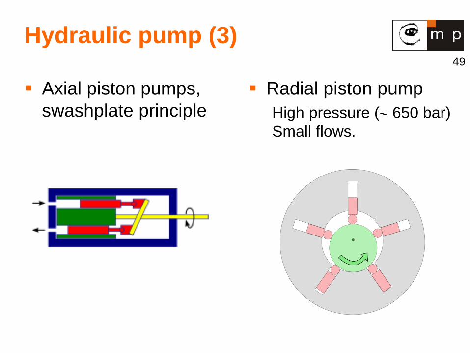
Hydraulic pump (3)
Axial piston pumps, swashplate principle
Radial piston pump High pressure (∼ 650 bar) Small flows.
50
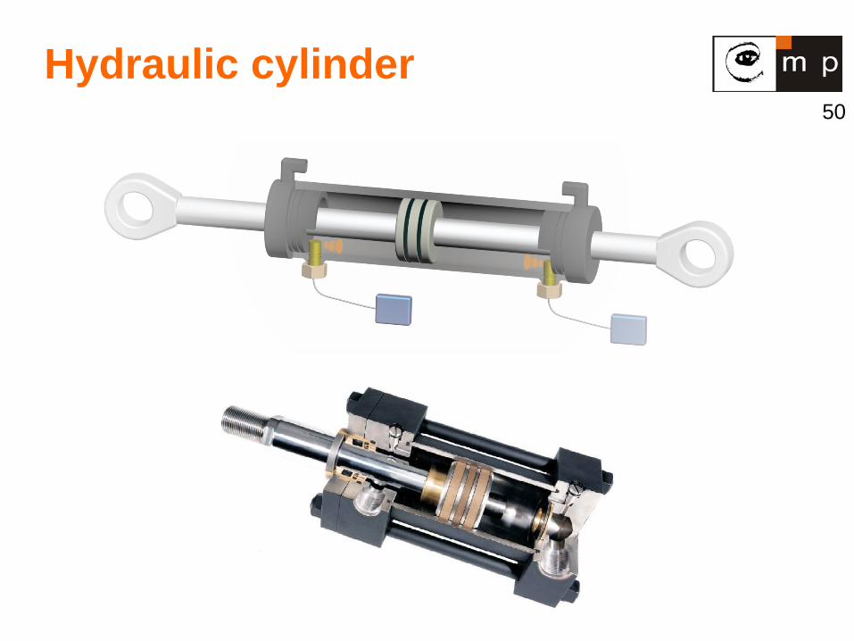
Hydraulic cylinder

51
Vane motor
52
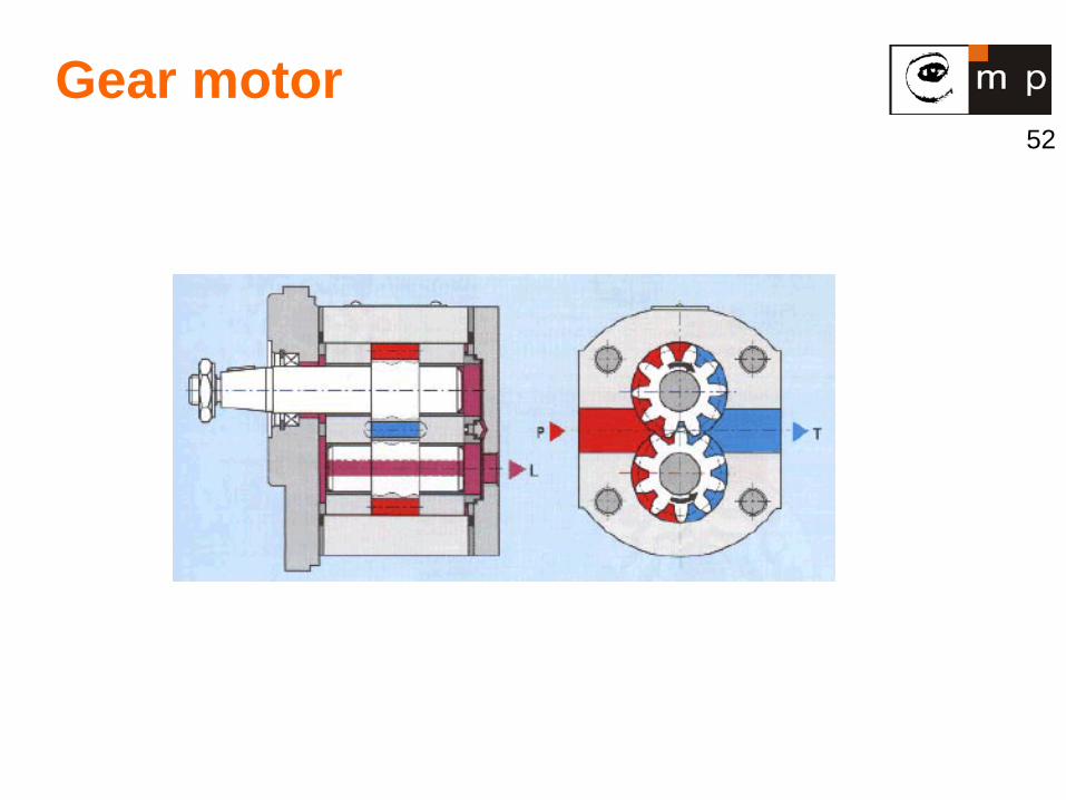
Gear motor
53
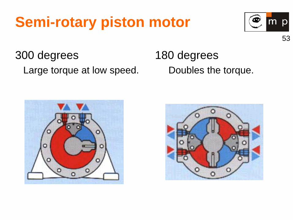
Semi-rotary piston motor
300 degrees Large torque at low speed.
180 degrees Doubles the torque.
54
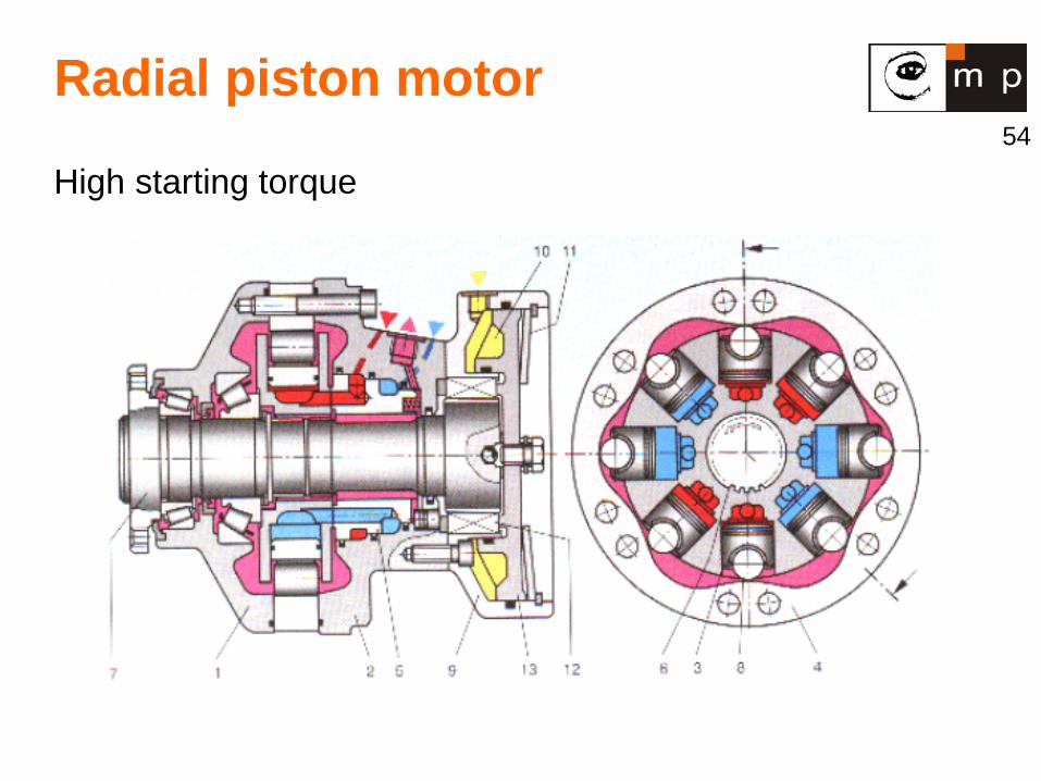
Radial piston motor
High starting torque
55
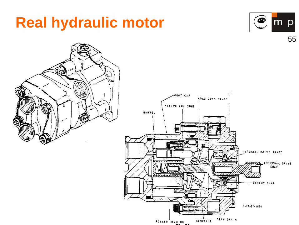
Real hydraulic motor
56
Pneumatic actuators
Like hydraulic except power from compressed air. Advantages:
• Fast on/off type tasks. • Big forces with elasticity. • No hydraulic oil leak problems.
Disadvantage: • Speed control is not possible because the air
pressure depends on many variables that are out of control.
57
Other Actuators
Piezoelectric. Magnetic. Ultrasound. Shape Memory Alloys (SMA). Inertial.
58
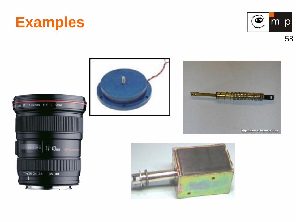
Examples
59
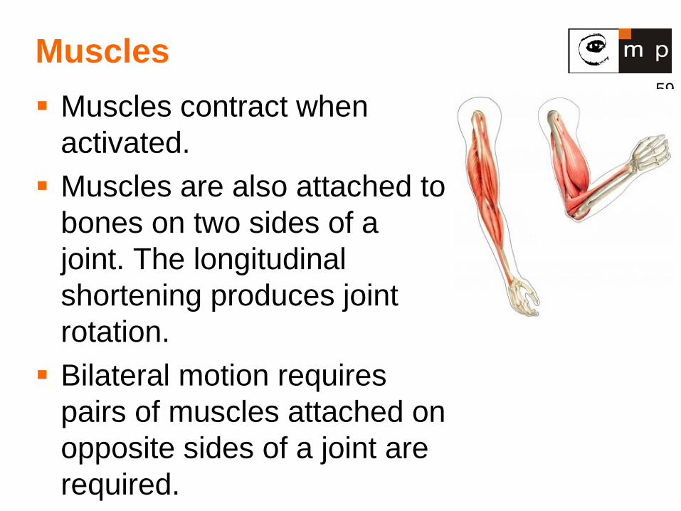
Muscles Muscles contract when
activated. Muscles are also attached to
bones on two sides of a joint. The longitudinal shortening produces joint rotation. Bilateral motion requires
pairs of muscles attached on opposite sides of a joint are required.
60
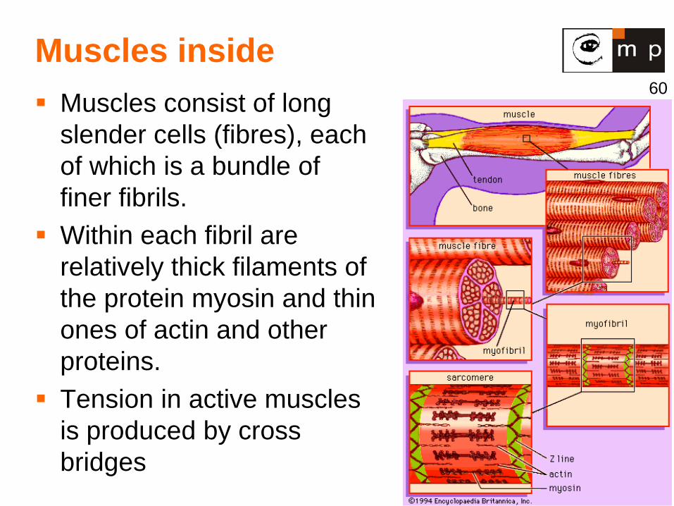
Muscles inside Muscles consist of long
slender cells (fibres), each of which is a bundle of finer fibrils.
Within each fibril are relatively thick filaments of the protein myosin and thin ones of actin and other proteins.
Tension in active muscles is produced by cross bridges
61
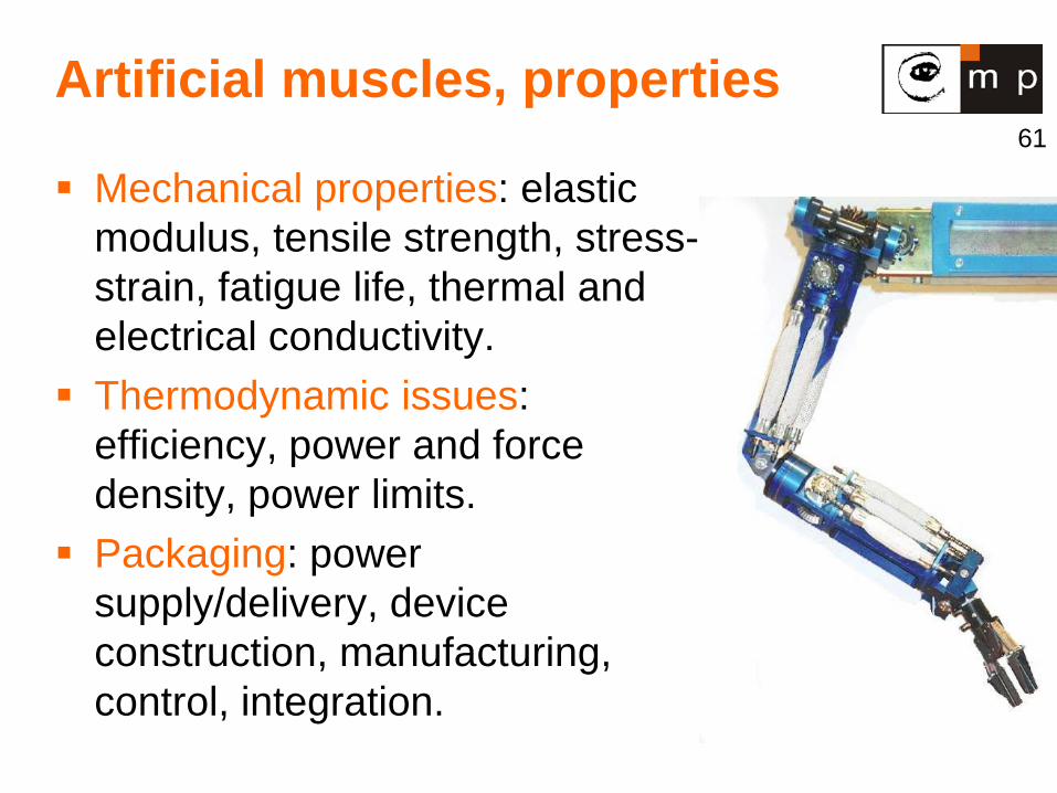
Artificial muscles, properties
Mechanical properties: elastic modulus, tensile strength, stress-strain, fatigue life, thermal and electrical conductivity.
Thermodynamic issues: efficiency, power and force density, power limits.
Packaging: power supply/delivery, device construction, manufacturing, control, integration.
62
Artificial muscles, technology 1 1. Traditional mechatronic muscles, e.g. pneumatic. 2. Shape memory alloys, e.g. NiTi. 3. Chemical polymers - gels (Jello, vitreous humor)
1000-fold volume change ~ temp, pH, electric fields. Force up to 100 N/cm2.
25 μm fiber → 1 Hz, 1 cm fiber → 1 cycle/2.5 days.
4. Electro active polymers Store electrons in large molecules. Deformation
~ (voltage)2.
Change length of chemical bonds.
63
Artificial muscles, technology 2 5. Biological Muscle Proteins
Actin and myosin. 0.001 mm/sec in a petri dish.
6. Fullerenes and Nanotubes Graphitic carbon. High elastic modulus → large displacements,
large forces. Macro-, micro-, and nano-scale Potentially superior to biological muscle.
64
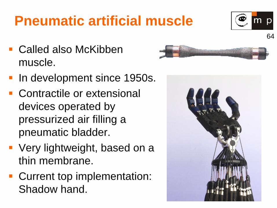
Pneumatic artificial muscle
Called also McKibben muscle.
In development since 1950s. Contractile or extensional
devices operated by pressurized air filling a pneumatic bladder.
Very lightweight, based on a thin membrane.
Current top implementation: Shadow hand.
65
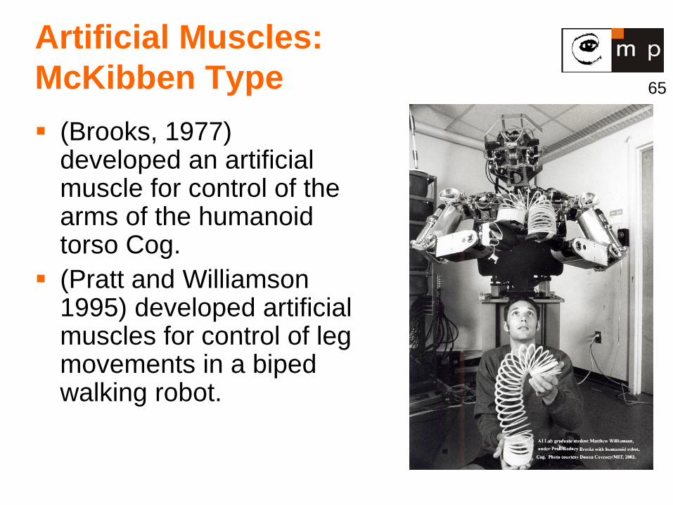
Artificial Muscles: McKibben Type (Brooks, 1977)
developed an artificial muscle for control of the arms of the humanoid torso Cog.
(Pratt and Williamson 1995) developed artificial muscles for control of leg movements in a biped walking robot.
66
Shape memory alloys 1
Nickel Titanium – Nitinol. Crystalographic phase transformation from
Martesite to Austenite. Contract 5-7% of length when heated - 100 times
greater effect than thermal expansion. Relatively high forces. About 1 Hz. Structural fatigue – a failure mode caused by
which cyclic loading which results in catastrophic fraction.
67
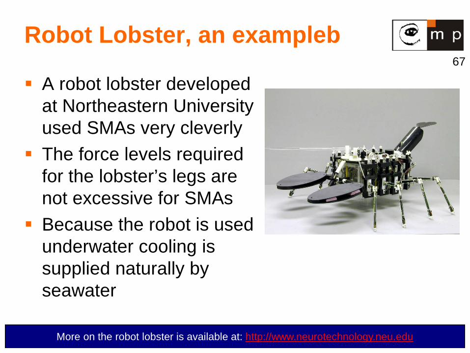
Robot Lobster, an exampleb
A robot lobster developed at Northeastern University used SMAs very cleverly
The force levels required for the lobster’s legs are not excessive for SMAs
Because the robot is used underwater cooling is supplied naturally by seawater
More on the robot lobster is available at: http://www.neurotechnology.neu.edu
68
Artificial Muscles: Electroactive Polymers Like SMAs, Electroactive Polymers (EAPs) also change their shape when electrically stimulated The advantages of EAPs for robotics are that they are able to emulate biological muscles with a high degree of toughness, large actuation strain, and inherent vibration damping Unfortunately, the force actuation and mechanical energy density of EAPs are relatively low
69
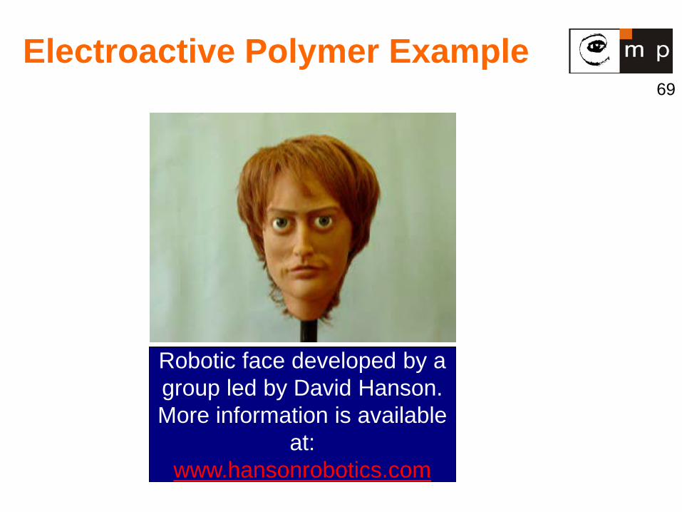
Electroactive Polymer Example
Robotic face developed by a group led by David Hanson. More information is available
at: www.hansonrobotics.com