Embed Size (px)
Citation preview
8/3/2019 Robotics Part3
http://slidepdf.com/reader/full/robotics-part3 1/87
Robot Programming
• Robot Programming is the defining ofdesired motions so that the robot mayperform them without human intervention.
– identifying and specifying the robotconfigurations (i.e. the pose of the end-effector, Pe, with respect to the base-frame)
8/3/2019 Robotics Part3
http://slidepdf.com/reader/full/robotics-part3 2/87
Work space
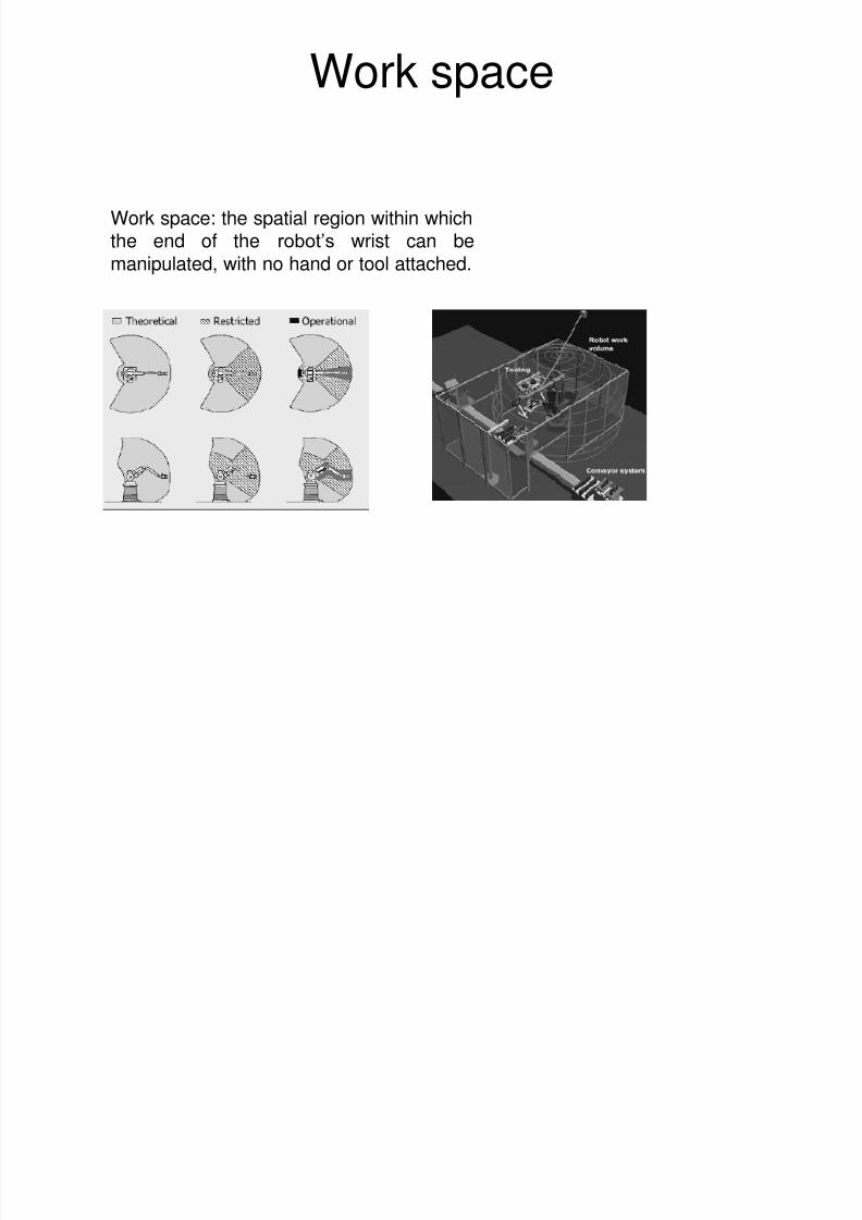
Work space: the spatial region within whichthe end of the robot’s wrist can be
manipulated, with no hand or tool attached.
8/3/2019 Robotics Part3
http://slidepdf.com/reader/full/robotics-part3 3/87
Type of Robot Programming
• Joint level programming– basic actions are positions (and possibly
movements) of the individual joints of therobot arm: joint angles in the case of rotational joints and linear positions in the
case of linear or prismatic joints.• Robot-level programming
– the basic actions are positions andorientations (and perhaps trajectories) of Pe and the frame of reference attached to it.
• High-level programming– Object-level programming
– Task-level programming
8/3/2019 Robotics Part3
http://slidepdf.com/reader/full/robotics-part3 4/87
Robot programming• A robot must be programmed to do useful works and
perform its tasks – a robot is an idiot waiting for you tomake it work by the use of programming.
• Robot program is defined as a path of movements of itsmanipulator, combined with peripheral equipment
actions to support its work cycle.• The peripheral equipment actions include
– Operation of the end-effector.
– Making logical decisions.
– Communicating with environments.
• A robot programmer needs to understand the whole taskand interfaces with its environment before he/she startsa programming.
8/3/2019 Robotics Part3
http://slidepdf.com/reader/full/robotics-part3 5/87
Robot programming method
• Walk-through method OR Manual (limited-sequence
robots)
• Lead-through method (teach-by-showing the desired motion
‘ Manual and Powered’ – adequate for shop floor operators)
• Computer like robot programming languages (requires
computer background, enhanced sensor capabilities, improved
control, computation capabilities, communications,
compatibility with CIM)
• Off-Line programming ( doesn’t interrupt production)
• Robot Simulation
8/3/2019 Robotics Part3
http://slidepdf.com/reader/full/robotics-part3 6/87
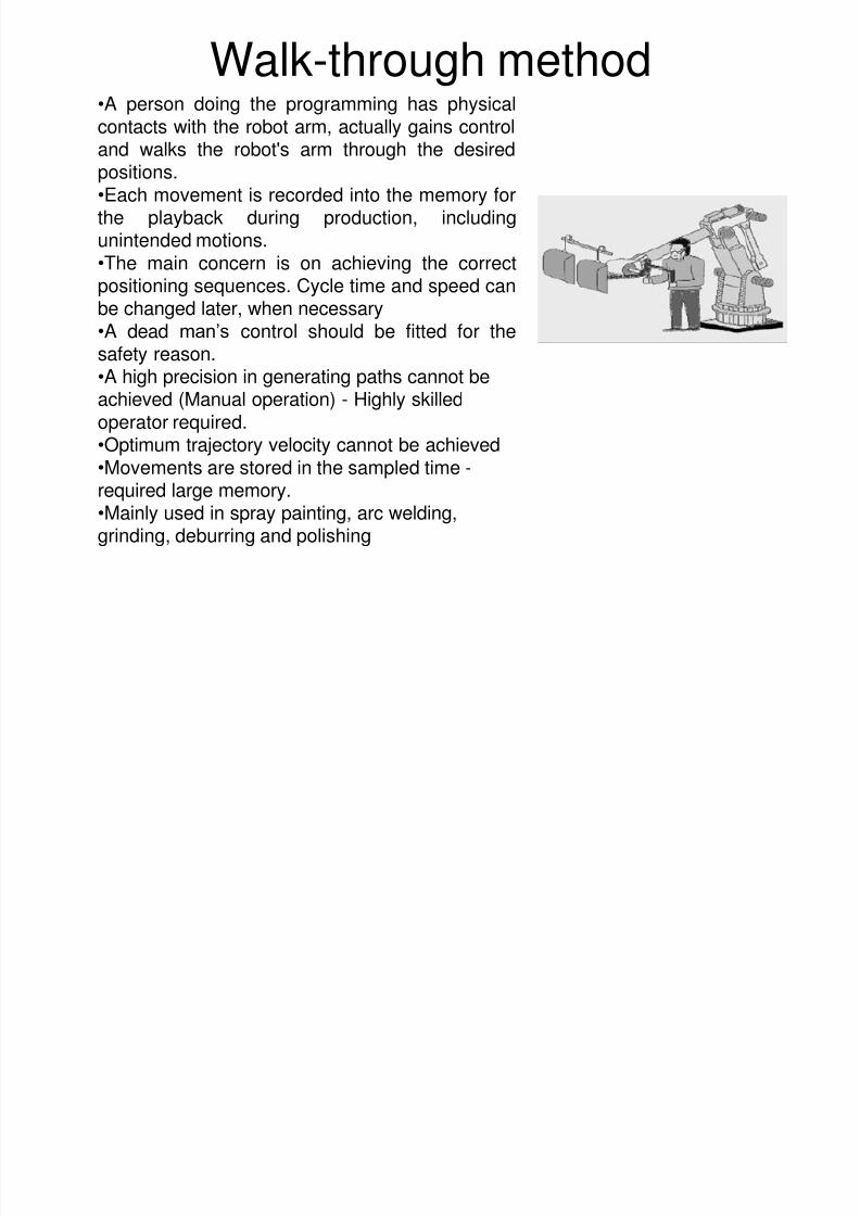
Walk-through method•A person doing the programming has physical
contacts with the robot arm, actually gains controland walks the robot's arm through the desiredpositions.•Each movement is recorded into the memory forthe playback during production, includingunintended motions.
•The main concern is on achieving the correctpositioning sequences. Cycle time and speed canbe changed later, when necessary•A dead man’s control should be fitted for thesafety reason.•A high precision in generating paths cannot be
achieved (Manual operation) - Highly skilledoperator required.•Optimum trajectory velocity cannot be achieved•Movements are stored in the sampled time -required large memory.•Mainly used in spray painting, arc welding,
grinding, deburring and polishing
8/3/2019 Robotics Part3
http://slidepdf.com/reader/full/robotics-part3 7/87
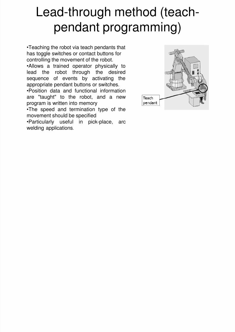
Lead-through method (teach-pendant programming)
•Teaching the robot via teach pendants thathas toggle switches or contact buttons forcontrolling the movement of the robot.•Allows a trained operator physically to
lead the robot through the desiredsequence of events by activating theappropriate pendant buttons or switches.•Position data and functional informationare "taught" to the robot, and a newprogram is written into memory
•The speed and termination type of themovement should be specified•Particularly useful in pick-place, arcwelding applications.
8/3/2019 Robotics Part3
http://slidepdf.com/reader/full/robotics-part3 8/87
Leadthrough Programming : Powered
• Each axis is moved under push-button control using a“teach” pendant to produce a series of desiredposition of the end point. Typical command keys:
JOG HOME TEACH MOVE
• The corresponding series of joint positions or pointsare stored for playback later during actual operation.
• Suitable for PTP control only since paths betweentwo consecutive positions are not predictable.
8/3/2019 Robotics Part3
http://slidepdf.com/reader/full/robotics-part3 9/87
Leadthrough Programming : Manual
• The entire path is “taught” by manually movingthrough the motion sequence. The measured positionsof the joints and speeds (how?) are recorded aseditable programs for later playback during actual
operation.• For large robot, a special programming device
replaces the actual robot.
• Used for Continuous Path programming . A typical
application of this programming method is spray painting where smooth and free flowing movementsare required.
8/3/2019 Robotics Part3
http://slidepdf.com/reader/full/robotics-part3 10/87
Computer like Robot Programming Languages :
Basic Elements
• Define Constants and Variables
• Motion commands (coordinate systems)
• End Effectors Commands• Sensor Commands
• Program Control Commands
• Communications Commands• Monitor Mode Commands
8/3/2019 Robotics Part3
http://slidepdf.com/reader/full/robotics-part3 11/87
Robot Programming Languages
• Wave
– Developed at Standford
– Demonstrated a robot hand-eye coordination in the machinevision robot
– Trajectory calculations through coordination of joint movements,end-effector positions and touch sensing
– Algorithm is too complex and not user friendly
• AL
– Later developed at Standford
– The language can implement various subroutines, involvingactivities between the robot and its surroundings.
8/3/2019 Robotics Part3
http://slidepdf.com/reader/full/robotics-part3 12/87
Robot Programming Languages
• Val
– Popular textual robot language developed byUnimation Inc. for the PUMA series of robots.
– Victor Sheinman developed VAL languages. – Later VAL II is developed
– It provides arm movement in joint, world and toolcoordinates, gripping and speed control.
• AML – Developed by IBM
– It is possible to interface other programminglanguages.
8/3/2019 Robotics Part3
http://slidepdf.com/reader/full/robotics-part3 13/87
Robot Programming Languages
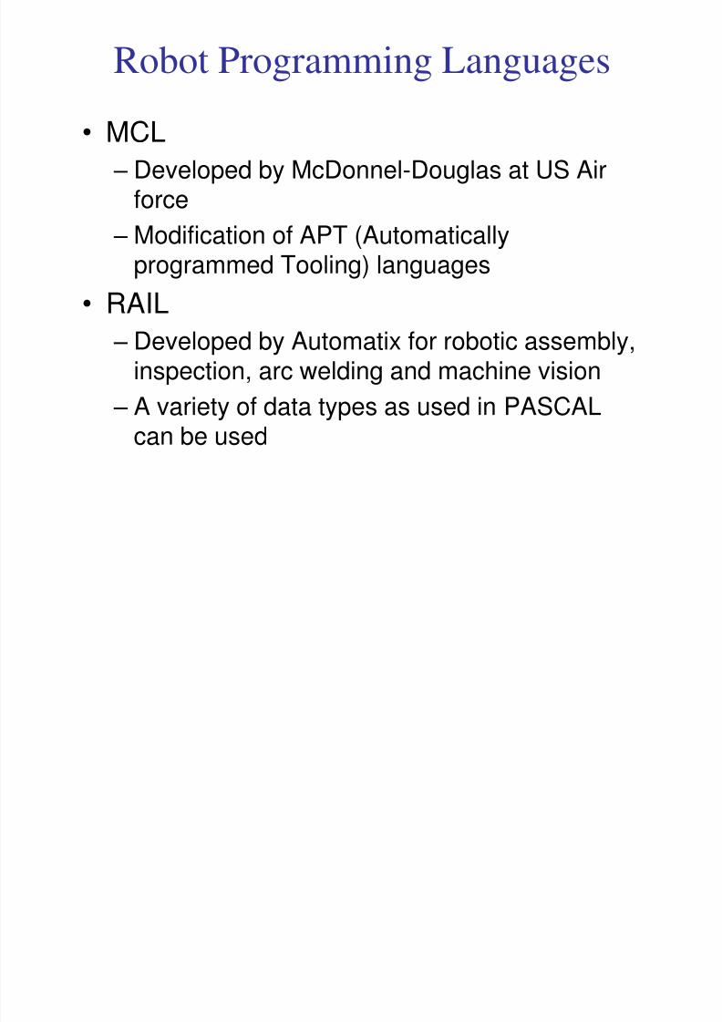
• MCL
– Developed by McDonnel-Douglas at US Airforce
– Modification of APT (Automaticallyprogrammed Tooling) languages
• RAIL
– Developed by Automatix for robotic assembly,inspection, arc welding and machine vision
– A variety of data types as used in PASCAL
can be used
8/3/2019 Robotics Part3
http://slidepdf.com/reader/full/robotics-part3 14/87
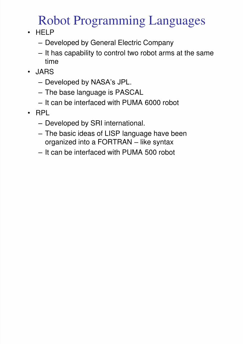
Robot Programming Languages • HELP
– Developed by General Electric Company
– It has capability to control two robot arms at the sametime
•JARS – Developed by NASA’s JPL.
– The base language is PASCAL
– It can be interfaced with PUMA 6000 robot
• RPL – Developed by SRI international.
– The basic ideas of LISP language have beenorganized into a FORTRAN – like syntax
– It can be interfaced with PUMA 500 robot
8/3/2019 Robotics Part3
http://slidepdf.com/reader/full/robotics-part3 15/87
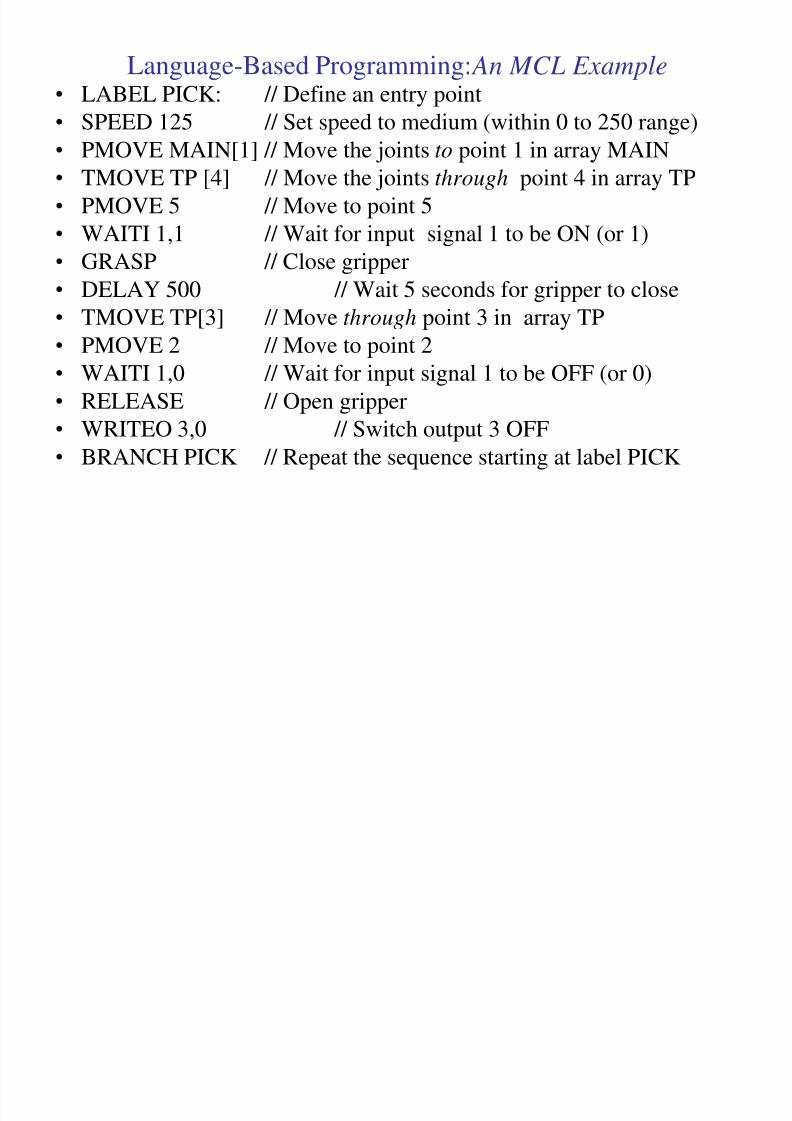
Language-Based Programming: An MCL Example• LABEL PICK: // Define an entry point
• SPEED 125 // Set speed to medium (within 0 to 250 range)• PMOVE MAIN[1] // Move the joints to point 1 in array MAIN
• TMOVE TP [4] // Move the joints through point 4 in array TP
• PMOVE 5 // Move to point 5
• WAITI 1,1 // Wait for input signal 1 to be ON (or 1)
• GRASP // Close gripper
• DELAY 500 // Wait 5 seconds for gripper to close
• TMOVE TP[3] // Move through point 3 in array TP
• PMOVE 2 // Move to point 2
• WAITI 1,0 // Wait for input signal 1 to be OFF (or 0)• RELEASE // Open gripper
• WRITEO 3,0 // Switch output 3 OFF
• BRANCH PICK // Repeat the sequence starting at label PICK
8/3/2019 Robotics Part3
http://slidepdf.com/reader/full/robotics-part3 16/87
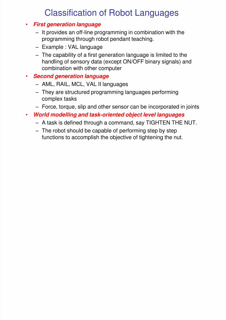
Classification of Robot Languages• First generation language
– It provides an off-line programming in combination with theprogramming through robot pendant teaching.
– Example : VAL language
– The capability of a first generation language is limited to thehandling of sensory data (except ON/OFF binary signals) and
combination with other computer• Second generation language
– AML, RAIL, MCL, VAL II languages
– They are structured programming languages performingcomplex tasks
– Force, torque, slip and other sensor can be incorporated in joints
• World modelling and task-oriented object level languages
– A task is defined through a command, say TIGHTEN THE NUT.
– The robot should be capable of performing step by stepfunctions to accomplish the objective of tightening the nut.
8/3/2019 Robotics Part3
http://slidepdf.com/reader/full/robotics-part3 17/87
Off-Line programming
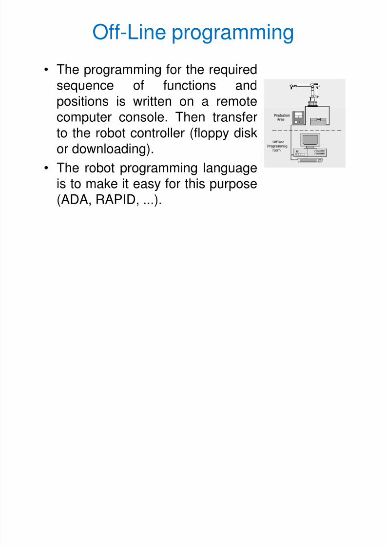
• The programming for the requiredsequence of functions andpositions is written on a remote
computer console. Then transferto the robot controller (floppy diskor downloading).
• The robot programming language
is to make it easy for this purpose(ADA, RAPID, ...).
8/3/2019 Robotics Part3
http://slidepdf.com/reader/full/robotics-part3 18/87
Off-Line programming
• Use of production equipment during programming - productivity notaffected
• Creating the program is safer since the programmer is not in the cell
• Communication with higher level of manufacturing system (ex.
CAD/CAM) is possible• Provide greater flexibility and high efficiency
• Safety is the main concern for off-line programming
• Most robot accidents do occur during programming, program touch-up or refinement, setup, or adjustment
• During these operations, the operator may temporarily be within therobot's working envelope where unintended operations could resultin injuries
• Requires highly skilled operator – computer programming + robotlanguage programming
8/3/2019 Robotics Part3
http://slidepdf.com/reader/full/robotics-part3 19/87
Robot Simulation
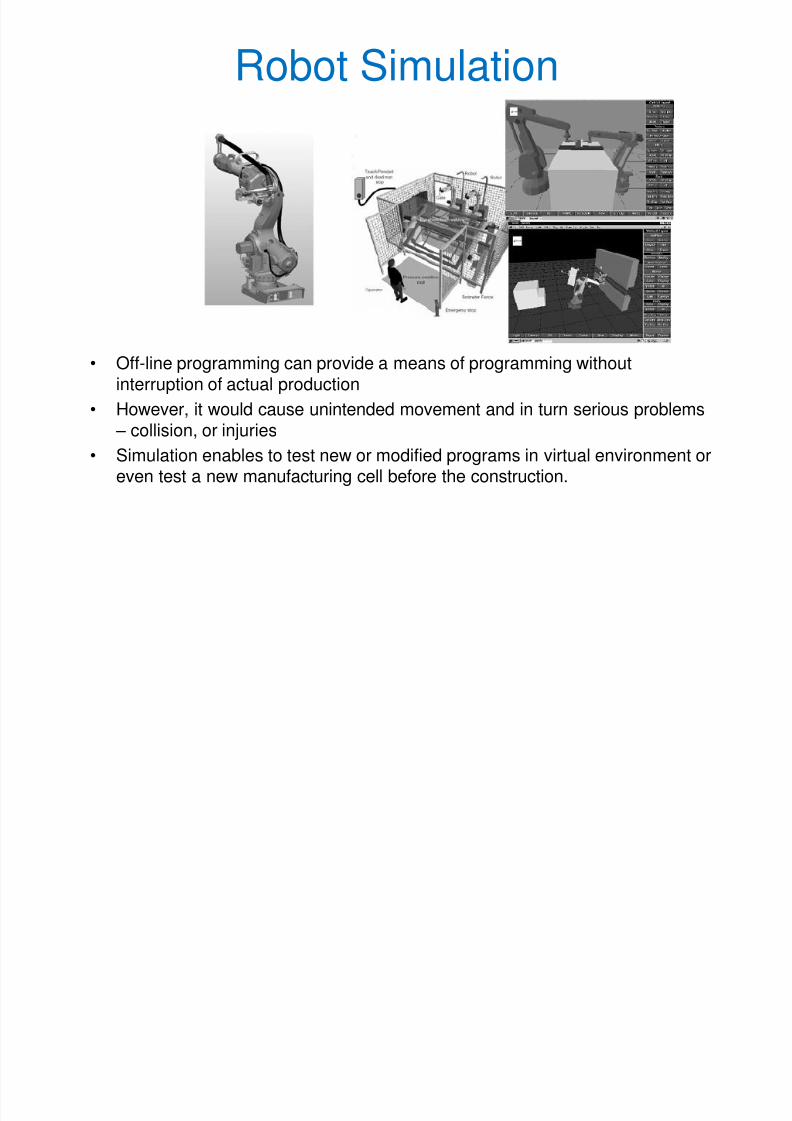
• Off-line programming can provide a means of programming withoutinterruption of actual production
• However, it would cause unintended movement and in turn serious problems – collision, or injuries
• Simulation enables to test new or modified programs in virtual environment oreven test a new manufacturing cell before the construction.
8/3/2019 Robotics Part3
http://slidepdf.com/reader/full/robotics-part3 20/87
Robot Simulation
• During the simulation the followings to be checked.
1. Kinematic reach – robot needs to reach all ofitems.
2. Work-cell layout.3. Collision checking.
4. Motion timing.
5. Off-line programming – to create robot programs.
6. Logic, wiring and cable connection.7. Special application features – weld width for
welding, paint thickness for paint spraying, etc....
8/3/2019 Robotics Part3
http://slidepdf.com/reader/full/robotics-part3 21/87
VAL programming language
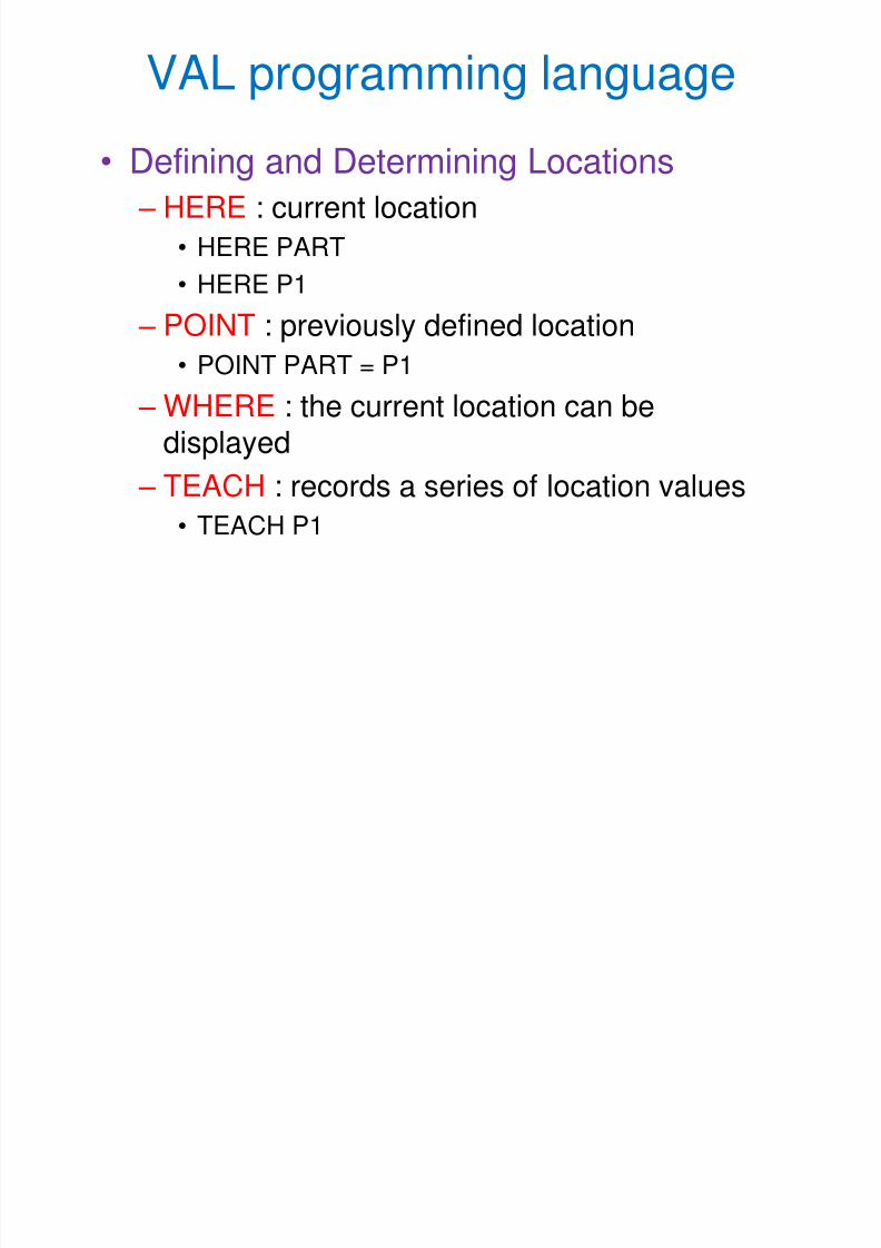
• Defining and Determining Locations
– HERE : current location
• HERE PART
• HERE P1
– POINT : previously defined location
• POINT PART = P1
– WHERE : the current location can bedisplayed
– TEACH : records a series of location values
• TEACH P1
8/3/2019 Robotics Part3
http://slidepdf.com/reader/full/robotics-part3 22/87
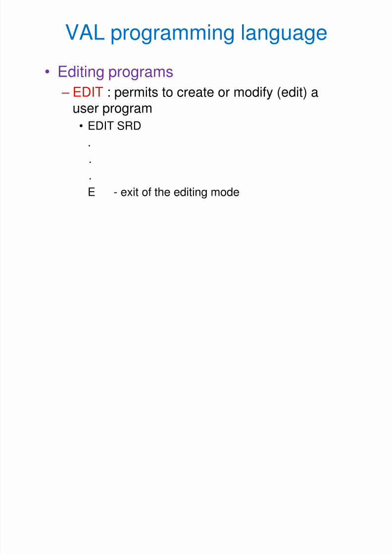
• Editing programs
– EDIT : permits to create or modify (edit) auser program
• EDIT SRD
.
.
.
E - exit of the editing mode
VAL programming language
8/3/2019 Robotics Part3
http://slidepdf.com/reader/full/robotics-part3 23/87
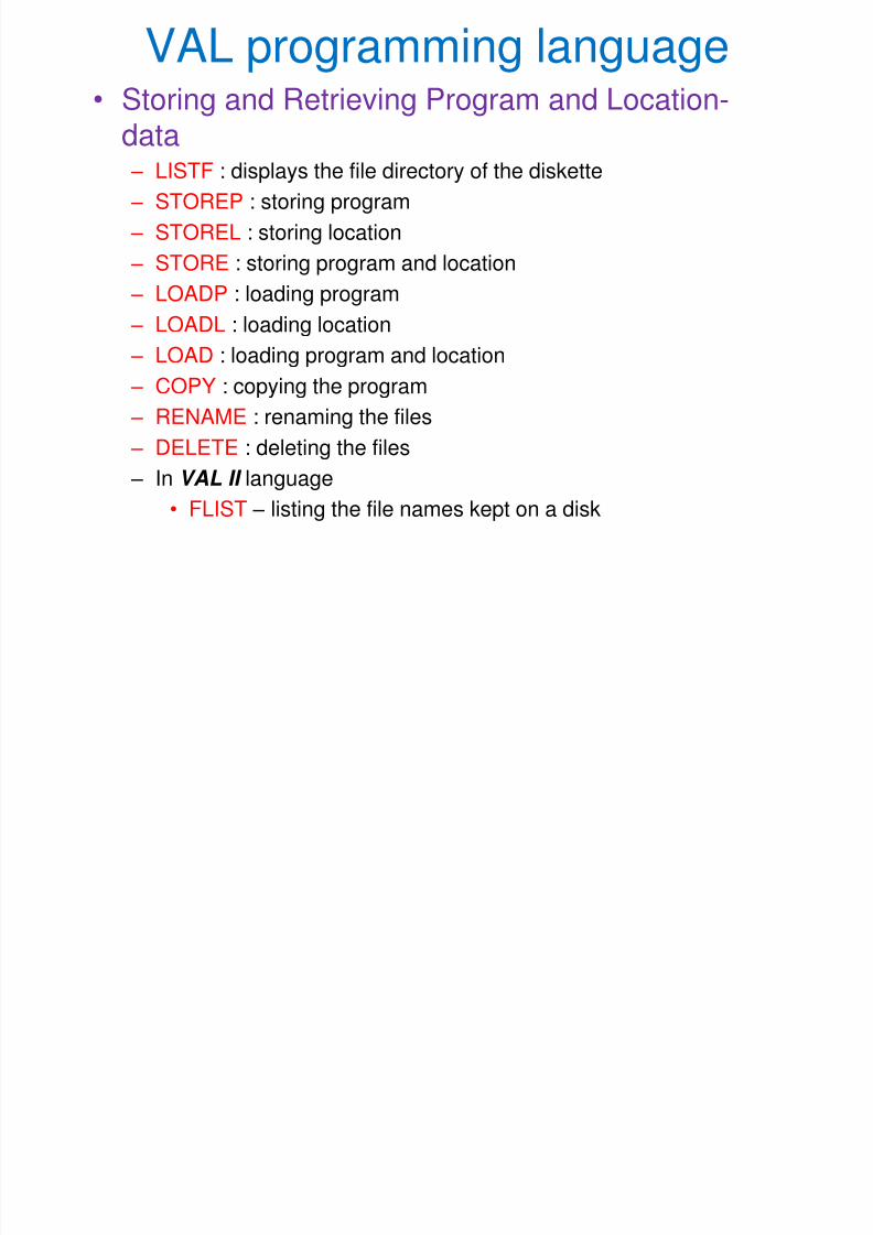
VAL programming language• Storing and Retrieving Program and Location-
data – LISTF : displays the file directory of the diskette
– STOREP : storing program
– STOREL : storing location
– STORE : storing program and location – LOADP : loading program
– LOADL : loading location
– LOAD : loading program and location
– COPY : copying the program
– RENAME : renaming the files
– DELETE : deleting the files
– In VAL II language
• FLIST – listing the file names kept on a disk
8/3/2019 Robotics Part3
http://slidepdf.com/reader/full/robotics-part3 24/87
VAL programming language
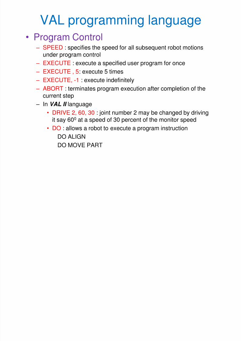
• Program Control – SPEED : specifies the speed for all subsequent robot motions
under program control
– EXECUTE : execute a specified user program for once
– EXECUTE , 5: execute 5 times
– EXECUTE, -1 : execute indefinitely
– ABORT : terminates program execution after completion of thecurrent step
– In VAL II language
• DRIVE 2, 60, 30 : joint number 2 may be changed by drivingit say 600 at a speed of 30 percent of the monitor speed
• DO : allows a robot to execute a program instruction
DO ALIGN
DO MOVE PART
8/3/2019 Robotics Part3
http://slidepdf.com/reader/full/robotics-part3 25/87
VAL programming language
• Program instructions
– Robot configuration control
– Motion control
– Hand control
– Location assignment and modification
– Program control, interlock commands and I/O
controls
8/3/2019 Robotics Part3
http://slidepdf.com/reader/full/robotics-part3 26/87
VAL programming language
• Robot configuration control
– Any robot configuration change is accomplishedduring the execution of the next motion instructionother than a straight line motion.
– RIGHTY : change the robot configuration to resemblea right human arm
– LEFTY : change the robot configuration to resemble aleft human arm
– ABOVE : make the elbow of the robot to point up
– BELOW : make the elbow of the robot to point down
8/3/2019 Robotics Part3
http://slidepdf.com/reader/full/robotics-part3 27/87
VAL programming language
• Motion Control – MOVE : moves the robot to specified location
– MOVES : moves the robot to straight line path
– DRAW : moves the robot to straight line through specifieddistance in X, Y and Z directions
– APPRO : moves the robot to location which is at an offset ( alongtool z-axis) from a specified point
– DEPART : moves the tool along the current tool Z-axis
– APPROS : moves the robot to location which is at an offset (
along tool z-axis) from a specified point in straight line path – DEPARTS : moves the tool along the current tool Z-axis in
straight line path
– CIRCLE : moves the robot through circular interpolation via threespecified point locations
8/3/2019 Robotics Part3
http://slidepdf.com/reader/full/robotics-part3 28/87
VAL programming language
• Hand Control
– OPEN : the opening of the gripper during the next instruction – CLOSE : the closing of the gripper during the next instruction
– OPENI : the opening of the gripper during the next instructionimmediately
– CLOSEI: the closing of the gripper during the next instruction immediately
– MOVEST PART, 30 : the servo-controlled end-effector causes a straightline motion to a point defined by PART and the gripper opening ischanged to 30 mm.
– MOVET PART, 30 : the gripper to move to position. PART with anopening of 30 mm by joint-interpolated motion.
– In VAL II language• CLOSEI 75 : if servo-controlled gripper is used, then this command
causes the gripper to close immediately to 75 mm.
• GRASP 20, 15 : the gripper to close immediately and checks whetherthe opening is less than the amount of 20 mm. If the opening is lessthan 20 mm, the program, branches to the statement 15.
8/3/2019 Robotics Part3
http://slidepdf.com/reader/full/robotics-part3 29/87
VAL programming language
• Location Assignment and Modification
– SET : set the value in the monitor
– HERE : position displayed on the screen
• Program Control, Interlock Commandsand Input / Output Control
– SETI : set the value of an integer variable to
the result of an expression.
– TYPEI : displays the name and valus of aninteger variable
8/3/2019 Robotics Part3
http://slidepdf.com/reader/full/robotics-part3 30/87
VAL programming language
• Program Control, Interlock Commands and Input / OutputControl
– In VAL II language
• PROMPT : the operator respond by typing the value requestedand pressing the return key.
– PROMPT “Enter the value” , Y1
– GOTO 20 : an unconditional branch to the program step identifiedby a given level, 20
– GOSUB : transfer the control to the subroutine
– RETURN : Transfer the control from the subroutine
– IF … THEN : transfer control to a program step depending on a
relationship (conditions) being true or falseIF ROW LT 3 THEN
(A number of instruction steps)
ELSE
(A number of instruction steps)
END
8/3/2019 Robotics Part3
http://slidepdf.com/reader/full/robotics-part3 31/87
VAL programming language
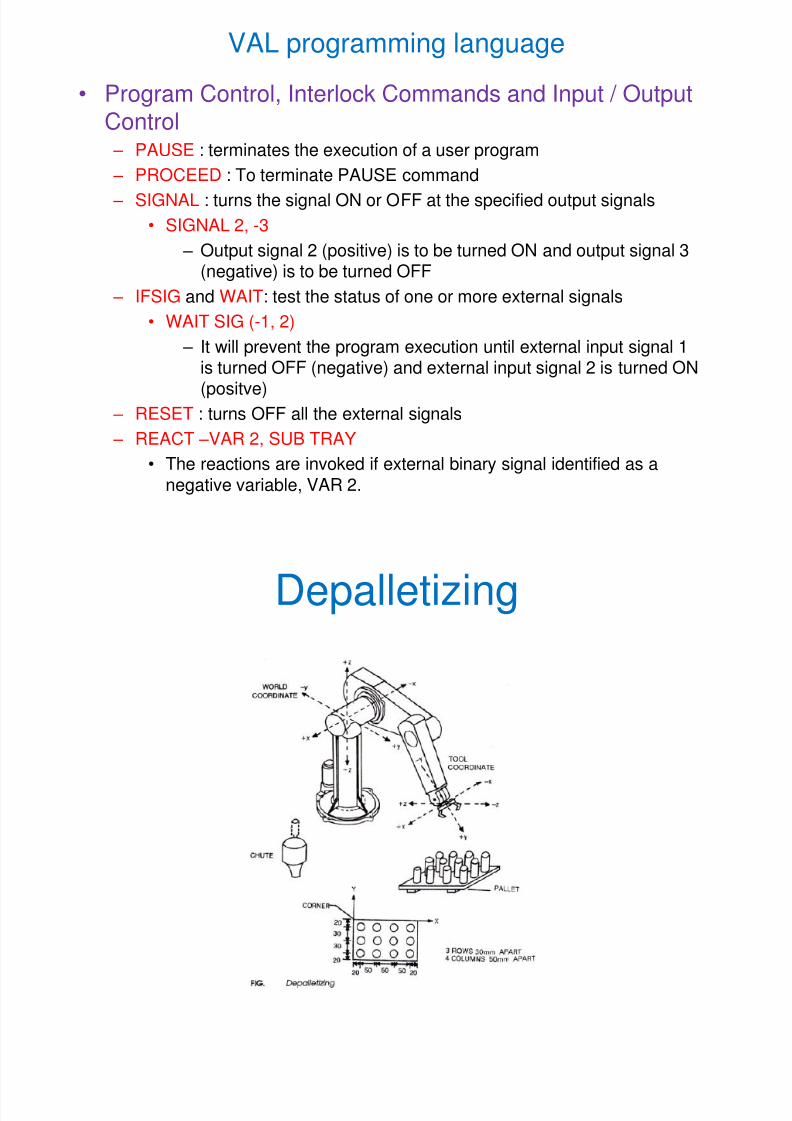
• Program Control, Interlock Commands and Input / Output
Control – PAUSE : terminates the execution of a user program
– PROCEED : To terminate PAUSE command
– SIGNAL : turns the signal ON or OFF at the specified output signals
• SIGNAL 2, -3
– Output signal 2 (positive) is to be turned ON and output signal 3(negative) is to be turned OFF
– IFSIG and WAIT: test the status of one or more external signals
• WAIT SIG (-1, 2)
– It will prevent the program execution until external input signal 1
is turned OFF (negative) and external input signal 2 is turned ON(positve)
– RESET : turns OFF all the external signals
– REACT –VAR 2, SUB TRAY
• The reactions are invoked if external binary signal identified as a
negative variable, VAR 2.
8/3/2019 Robotics Part3
http://slidepdf.com/reader/full/robotics-part3 32/87
Depalletizing
8/3/2019 Robotics Part3
http://slidepdf.com/reader/full/robotics-part3 33/87
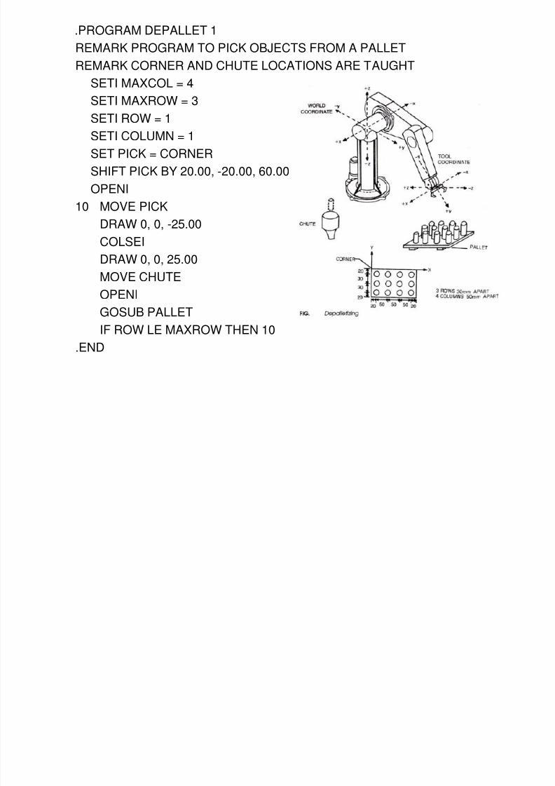
.PROGRAM DEPALLET 1
REMARK PROGRAM TO PICK OBJECTS FROM A PALLET
REMARK CORNER AND CHUTE LOCATIONS ARE TAUGHT
SETI MAXCOL = 4SETI MAXROW = 3
SETI ROW = 1
SETI COLUMN = 1
SET PICK = CORNER
SHIFT PICK BY 20.00, -20.00, 60.00OPENI
10 MOVE PICK
DRAW 0, 0, -25.00
COLSEI
DRAW 0, 0, 25.00MOVE CHUTE
OPENI
GOSUB PALLET
IF ROW LE MAXROW THEN 10
.END
8/3/2019 Robotics Part3
http://slidepdf.com/reader/full/robotics-part3 34/87
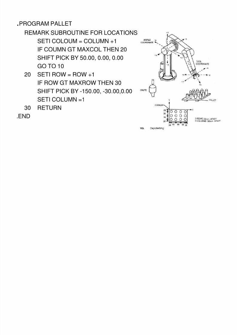
.PROGRAM PALLET
REMARK SUBROUTINE FOR LOCATIONS
SETI COLOUM = COLUMN +1
IF COUMN GT MAXCOL THEN 20
SHIFT PICK BY 50.00, 0.00, 0.00
GO TO 10
20 SETI ROW = ROW +1IF ROW GT MAXROW THEN 30
SHIFT PICK BY -150.00, -30.00,0.00
SETI COLUMN =1
30 RETURN
.END
8/3/2019 Robotics Part3
http://slidepdf.com/reader/full/robotics-part3 35/87
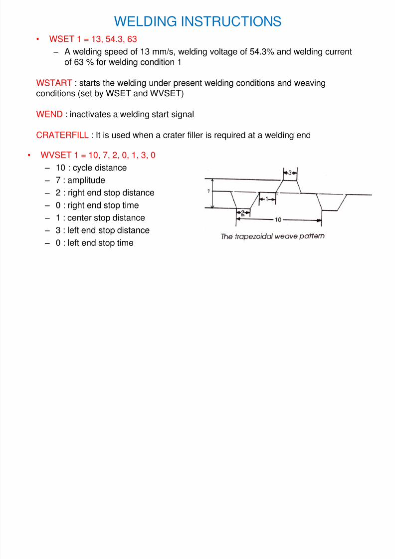
WELDING INSTRUCTIONS
• WVSET 1 = 10, 7, 2, 0, 1, 3, 0
– 10 : cycle distance
– 7 : amplitude
– 2 : right end stop distance
– 0 : right end stop time
– 1 : center stop distance
– 3 : left end stop distance
– 0 : left end stop time
• WSET 1 = 13, 54.3, 63
– A welding speed of 13 mm/s, welding voltage of 54.3% and welding current
of 63 % for welding condition 1
WSTART : starts the welding under present welding conditions and weavingconditions (set by WSET and WVSET)
WEND : inactivates a welding start signal
CRATERFILL : It is used when a crater filler is required at a welding end
An Arc Welding Program
8/3/2019 Robotics Part3
http://slidepdf.com/reader/full/robotics-part3 36/87
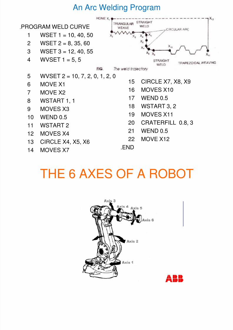
An Arc Welding Program
.PROGRAM WELD CURVE
1 WSET 1 = 10, 40, 502 WSET 2 = 8, 35, 60
3 WSET 3 = 12, 40, 55
4 WVSET 1 = 5, 5
5 WVSET 2 = 10, 7, 2, 0, 1, 2, 0
6 MOVE X1
7 MOVE X2
8 WSTART 1, 1
9 MOVES X310 WEND 0.5
11 WSTART 2
12 MOVES X4
13 CIRCLE X4, X5, X6
14 MOVES X7
15 CIRCLE X7, X8, X9
16 MOVES X10
17 WEND 0.5
18 WSTART 3, 2
19 MOVES X11
20 CRATERFILL 0.8, 3
21 WEND 0.5
22 MOVE X12
.END
8/3/2019 Robotics Part3
http://slidepdf.com/reader/full/robotics-part3 37/87
THE 6 AXES OF A ROBOT
8/3/2019 Robotics Part3
http://slidepdf.com/reader/full/robotics-part3 38/87
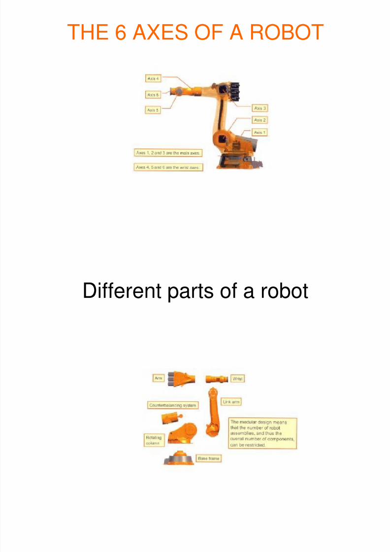
THE 6 AXES OF A ROBOT
8/3/2019 Robotics Part3
http://slidepdf.com/reader/full/robotics-part3 39/87
Different parts of a robot
8/3/2019 Robotics Part3
http://slidepdf.com/reader/full/robotics-part3 40/87
THE MAJOR AND MINOR AXESOF A ROBOT
• The first three axes of a robot are knownas the major axes because they help inpositioning the wrist at a required point on
the workpiece.
• The last three axes of a robot are called asthe minor axes because they allow the
wrist to reorient in any required directionwithout changing its position.
8/3/2019 Robotics Part3
http://slidepdf.com/reader/full/robotics-part3 41/87
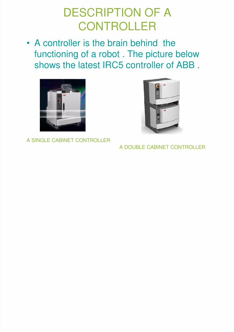
DESCRIPTION OF ACONTROLLER
• A controller is the brain behind thefunctioning of a robot . The picture belowshows the latest IRC5 controller of ABB .
A SINGLE CABINET CONTROLLER
A DOUBLE CABINET CONTROLLER
8/3/2019 Robotics Part3
http://slidepdf.com/reader/full/robotics-part3 42/87
MAJOR COMPONENTS OF ANIRC5 CONTROLLER
• A main computer does all the primary computing job.
• Axis computers perform all the calculations of individual joints.
• Drive units control the torque , acceleration and speed of
the joints.• The SMPS (Switch Mode Power Supply) supplies 24
VDC to main computer, axis computers, I/O Boards etc.
• The capacitor improves the power factor.
• Contactors cut off supply from motors as and whenrequired.
• Transformer steps down 440 VAC to 230 VAC.
• Rectifier converts AC to DC.
• I/O Boards are used for user signals.
8/3/2019 Robotics Part3
http://slidepdf.com/reader/full/robotics-part3 43/87
USE OF RESOLVERS AND SMB
• Every joint of a robot has a resolver , theresolver measures the position andvelocity of a joint and sends the data to the
SMB (Serial Measurement Board) locatedat the base of the manipulator.
• There is a separate battery for backing theSMB data in case of a power failure.
• The SMB is connected to the controller viaa resolver cable.
8/3/2019 Robotics Part3
http://slidepdf.com/reader/full/robotics-part3 44/87
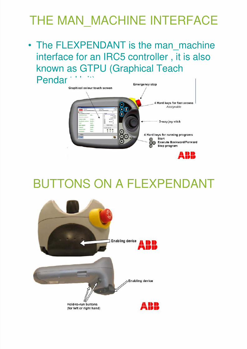
THE MAN_MACHINE INTERFACE
• The FLEXPENDANT is the man_machineinterface for an IRC5 controller , it is alsoknown as GTPU (Graphical Teach
Pendant Unit).
8/3/2019 Robotics Part3
http://slidepdf.com/reader/full/robotics-part3 45/87
BUTTONS ON A FLEXPENDANT
8/3/2019 Robotics Part3
http://slidepdf.com/reader/full/robotics-part3 46/87
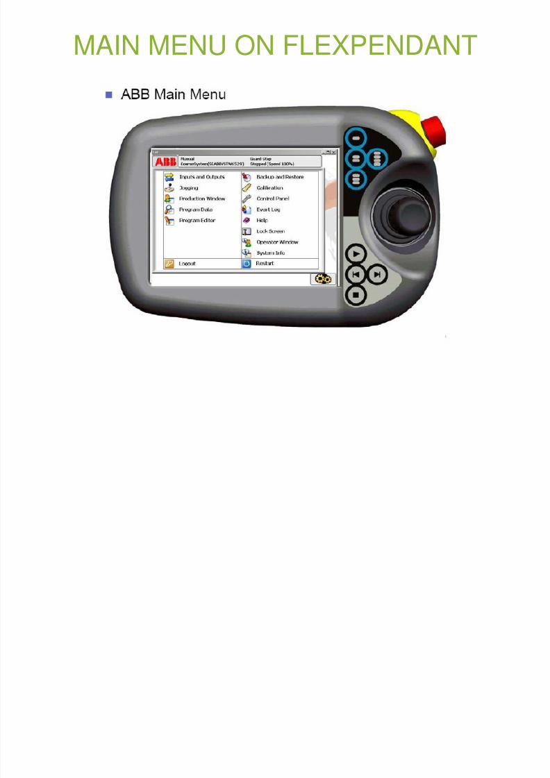
MAIN MENU ON FLEXPENDANT
8/3/2019 Robotics Part3
http://slidepdf.com/reader/full/robotics-part3 47/87
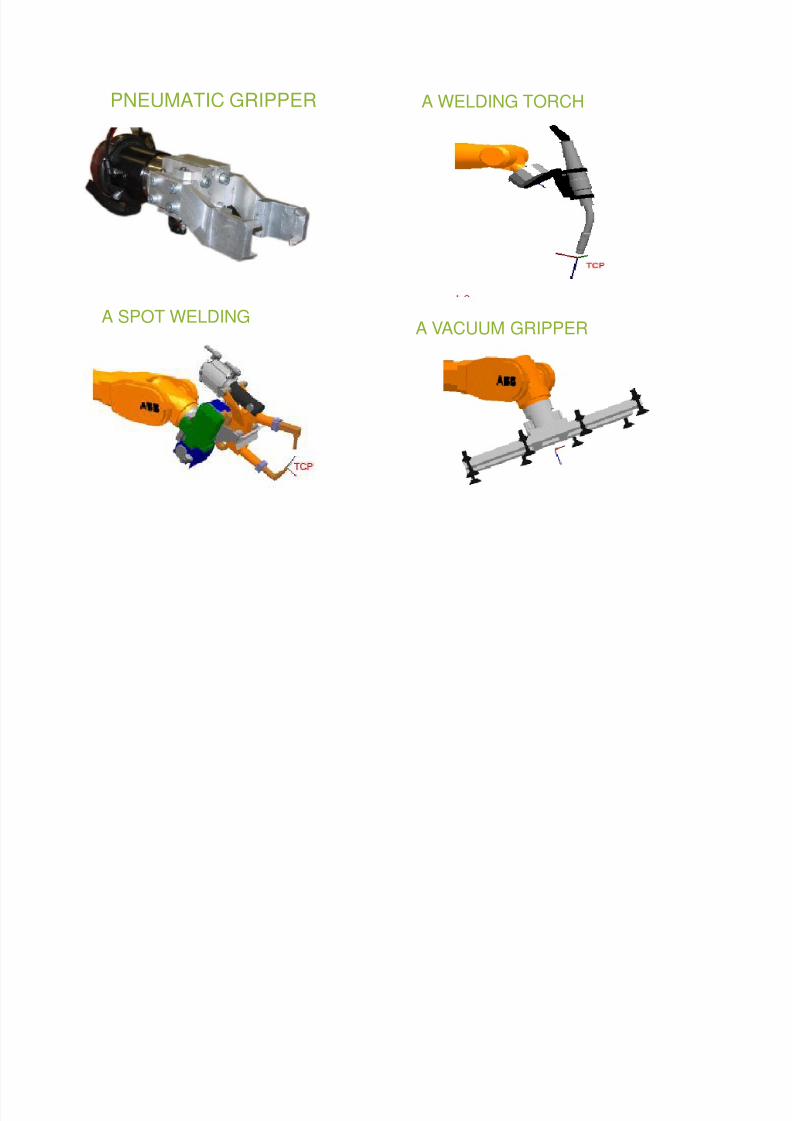
THE END_EFFECTOR
• The tool that is attached to the ToolMounting Flange of the robot is known asthe end_effector , it may be cutting tool,
drill bit, gripper (vacuum, pneumatic orservo), welding gun, hemming tool, gluegun etc.
8/3/2019 Robotics Part3
http://slidepdf.com/reader/full/robotics-part3 48/87
PNEUMATIC GRIPPER A WELDING TORCH
A VACUUM GRIPPER A SPOT WELDING
8/3/2019 Robotics Part3
http://slidepdf.com/reader/full/robotics-part3 49/87
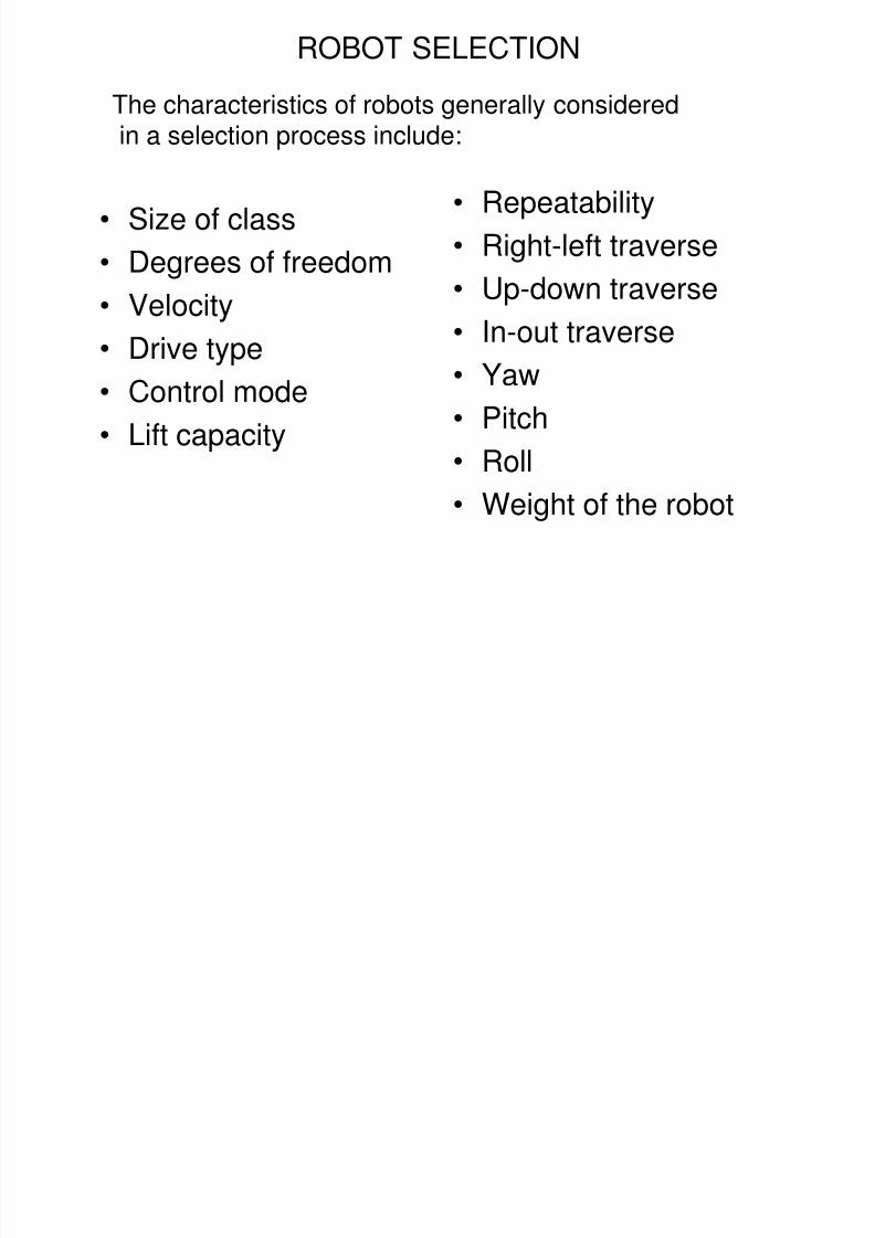
• Size of class
• Degrees of freedom• Velocity
• Drive type
• Control mode
• Lift capacity
• Repeatability
• Right-left traverse
• Up-down traverse
• In-out traverse
• Yaw
• Pitch• Roll
• Weight of the robot
ROBOT SELECTION
The characteristics of robots generally considered
in a selection process include:
8/3/2019 Robotics Part3
http://slidepdf.com/reader/full/robotics-part3 50/87
2004 50
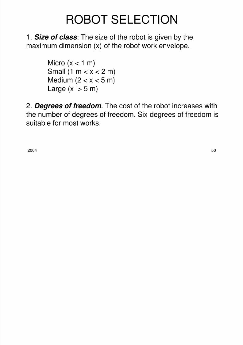
1. Size of class : The size of the robot is given by themaximum dimension (x) of the robot work envelope.
Micro (x < 1 m)Small (1 m < x < 2 m)
Medium (2 < x < 5 m)Large (x > 5 m)
2. Degrees of freedom . The cost of the robot increases with
the number of degrees of freedom. Six degrees of freedom issuitable for most works.
ROBOT SELECTION
8/3/2019 Robotics Part3
http://slidepdf.com/reader/full/robotics-part3 51/87
2004 51
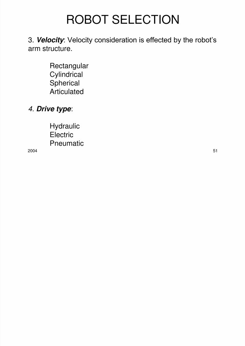
3. Velocity : Velocity consideration is effected by the robot’sarm structure.
Rectangular
CylindricalSphericalArticulated
4. Drive type :
HydraulicElectricPneumatic
ROBOT SELECTION
8/3/2019 Robotics Part3
http://slidepdf.com/reader/full/robotics-part3 52/87
2004 52
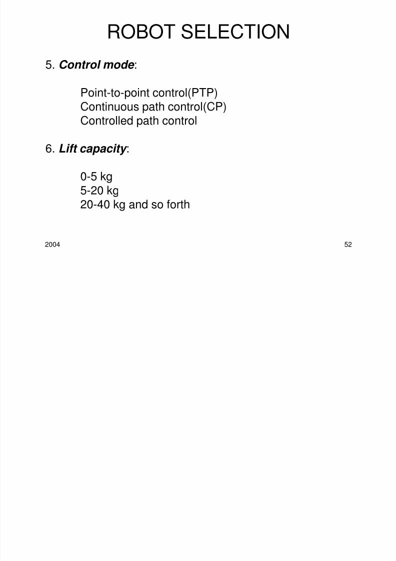
5. Control mode :
Point-to-point control(PTP)Continuous path control(CP)
Controlled path control
6. Lift capacity :
0-5 kg
5-20 kg20-40 kg and so forth
ROBOT SELECTION
8/3/2019 Robotics Part3
http://slidepdf.com/reader/full/robotics-part3 53/87
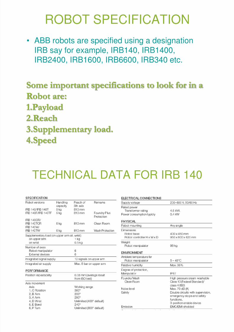
ROBOT SPECIFICATION
• ABB robots are specified using a designationIRB say for example, IRB140, IRB1400,IRB2400, IRB1600, IRB6600, IRB340 etc.
Some important specifications to look for in a
Robot are:
1.Payload2.Reach
3.Supplementary load.
4.Speed
8/3/2019 Robotics Part3
http://slidepdf.com/reader/full/robotics-part3 54/87
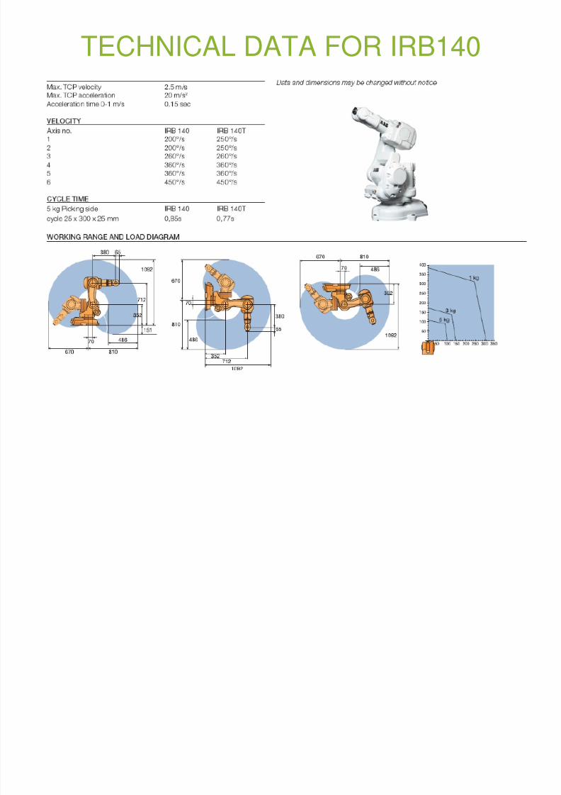
TECHNICAL DATA FOR IRB 140
8/3/2019 Robotics Part3
http://slidepdf.com/reader/full/robotics-part3 55/87
TECHNICAL DATA FOR IRB140
OPERATING MODES OF A
8/3/2019 Robotics Part3
http://slidepdf.com/reader/full/robotics-part3 56/87
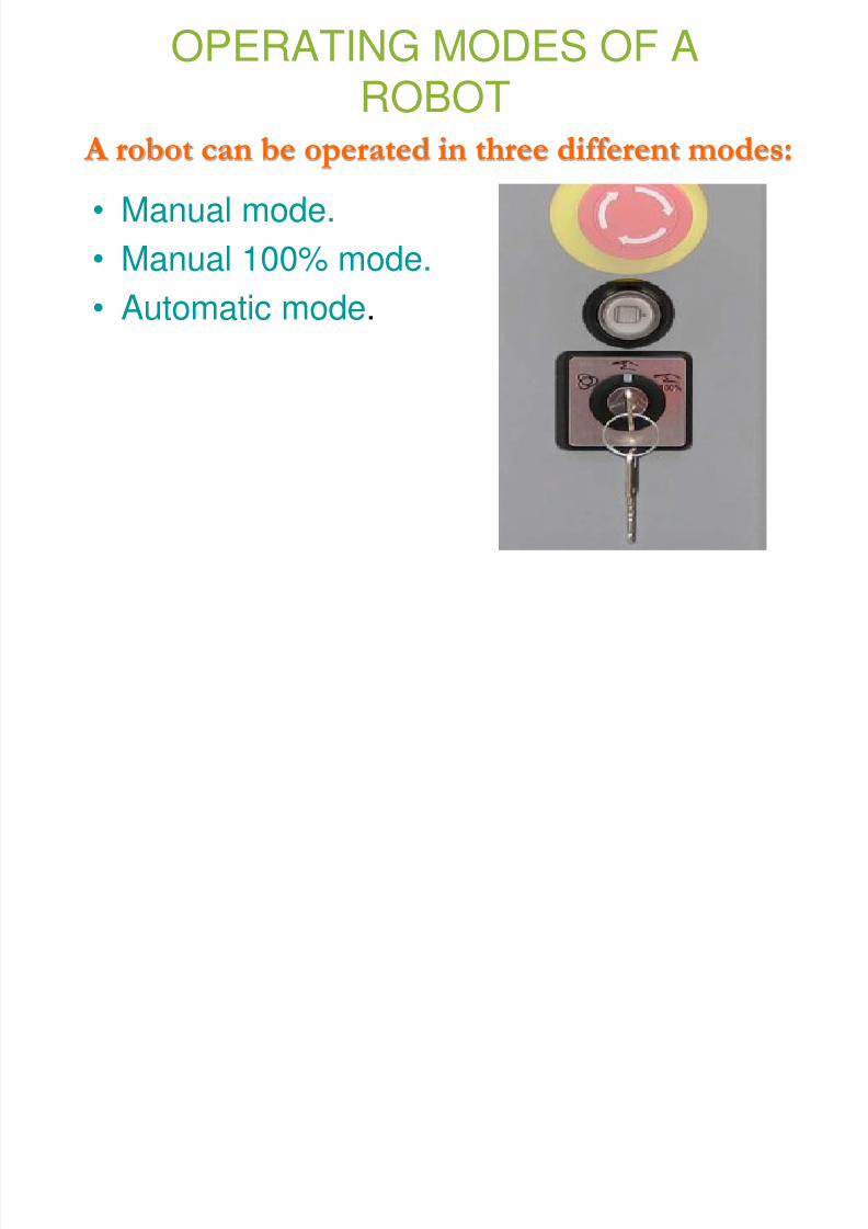
OPERATING MODES OF AROBOT
• Manual mode.
• Manual 100% mode.• Automatic mode.
A robot can be operated in three different modes:

8/3/2019 Robotics Part3
http://slidepdf.com/reader/full/robotics-part3 57/87
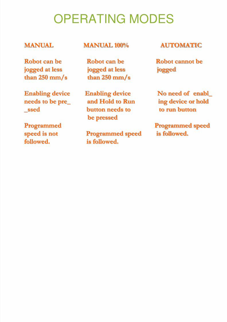
OPERATING MODES
MANUAL MANUAL 100% AUTOMATIC
Robot can be Robot can be Robot cannot be
jogged at less jogged at less joggedthan 250 mm/s than 250 mm/s
Enabling device Enabling device No need of enabl_
needs to be pre_ and Hold to Run ing device or hold
_ssed button needs to to run buttonbe pressed
Programmed Programmed speed
speed is not Programmed speed is followed.
followed. is followed.
8/3/2019 Robotics Part3
http://slidepdf.com/reader/full/robotics-part3 58/87
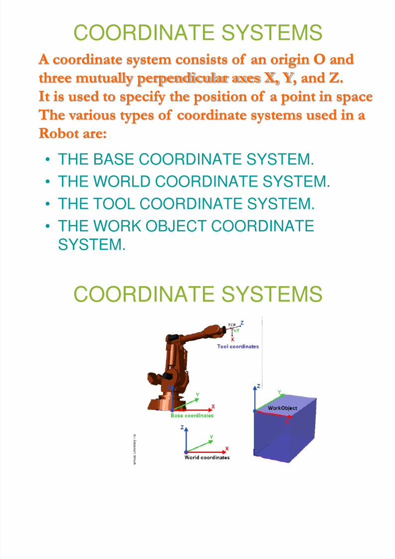
COORDINATE SYSTEMS
• THE BASE COORDINATE SYSTEM.
• THE WORLD COORDINATE SYSTEM.• THE TOOL COORDINATE SYSTEM.
• THE WORK OBJECT COORDINATE
SYSTEM.
A coordinate system consists of an origin O andthree mutually perpendicular axes X, Y, and Z.
It is used to specify the position of a point in space
The various types of coordinate systems used in a
Robot are:
8/3/2019 Robotics Part3
http://slidepdf.com/reader/full/robotics-part3 59/87
COORDINATE SYSTEMS
8/3/2019 Robotics Part3
http://slidepdf.com/reader/full/robotics-part3 60/87
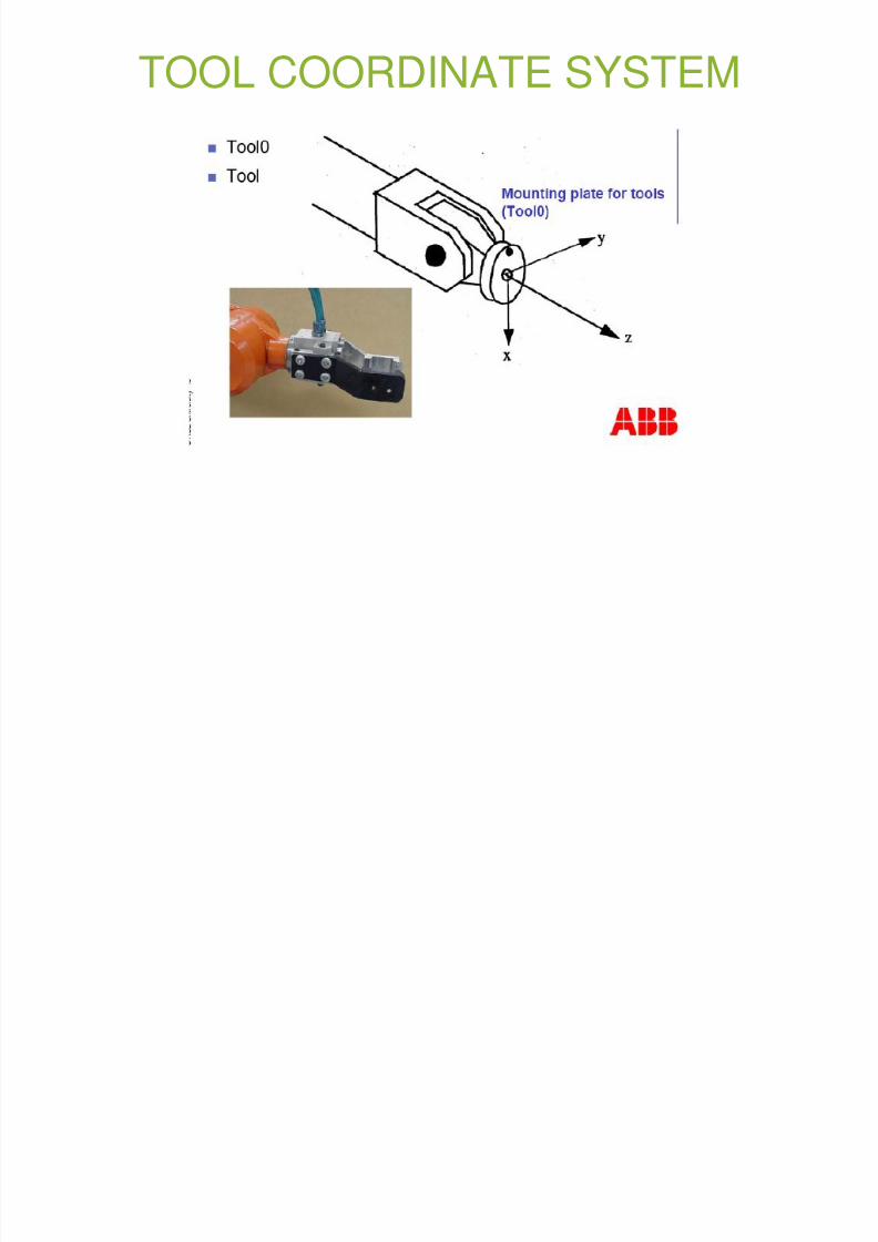
TOOL COORDINATE SYSTEM
8/3/2019 Robotics Part3
http://slidepdf.com/reader/full/robotics-part3 61/87
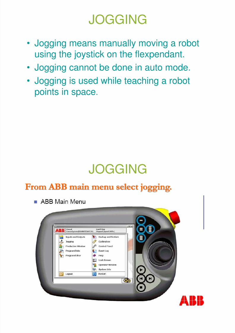
JOGGING
• Jogging means manually moving a robotusing the joystick on the flexpendant.
• Jogging cannot be done in auto mode.
• Jogging is used while teaching a robotpoints in space.
JOGGING
8/3/2019 Robotics Part3
http://slidepdf.com/reader/full/robotics-part3 62/87
JOGGING
From ABB main menu select jogging.
JOGGING WINDOW
8/3/2019 Robotics Part3
http://slidepdf.com/reader/full/robotics-part3 63/87
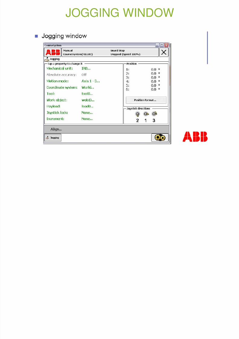
JOGGING WINDOW
8/3/2019 Robotics Part3
http://slidepdf.com/reader/full/robotics-part3 64/87
MODES OF JOGGING
Jogging can be done in three modes:
• Axes mode
• Linear mode
• Reorient mode
8/3/2019 Robotics Part3
http://slidepdf.com/reader/full/robotics-part3 65/87
AXIS MODE
• We can jog axes 1-3 or axes 4-6 at onego.
• The position format shows the angular
position of each joint in degrees orradians.
8/3/2019 Robotics Part3
http://slidepdf.com/reader/full/robotics-part3 66/87
LINEAR MODE
• In linear mode the TCP moves in a straight line.
• The TCP can move parallel to either the x-axisor the y-axis or the z-axis of the selected
coordinate system of the robot which can be thebase,world,tool or workobject coordinate system.
• The position format shows the position of theTCP w.r.t the coordinate system selected in mm
and orientation of tool in Quaternions or EulerAngles.
• During linear jogging orientation of tool remains
same.
8/3/2019 Robotics Part3
http://slidepdf.com/reader/full/robotics-part3 67/87
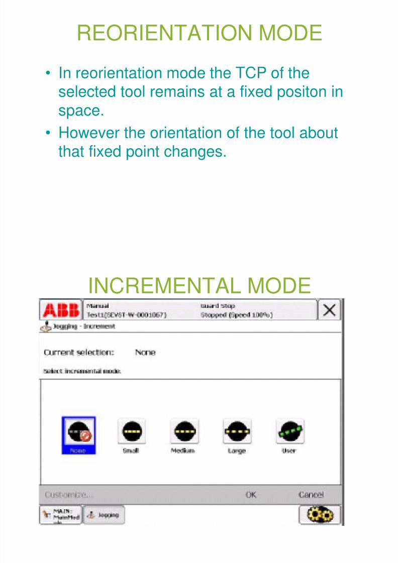
REORIENTATION MODE
• In reorientation mode the TCP of theselected tool remains at a fixed positon inspace.
• However the orientation of the tool aboutthat fixed point changes.
INCREMENTAL MODE
8/3/2019 Robotics Part3
http://slidepdf.com/reader/full/robotics-part3 68/87
INCREMENTAL MODE
QUICKSET MENU
8/3/2019 Robotics Part3
http://slidepdf.com/reader/full/robotics-part3 69/87
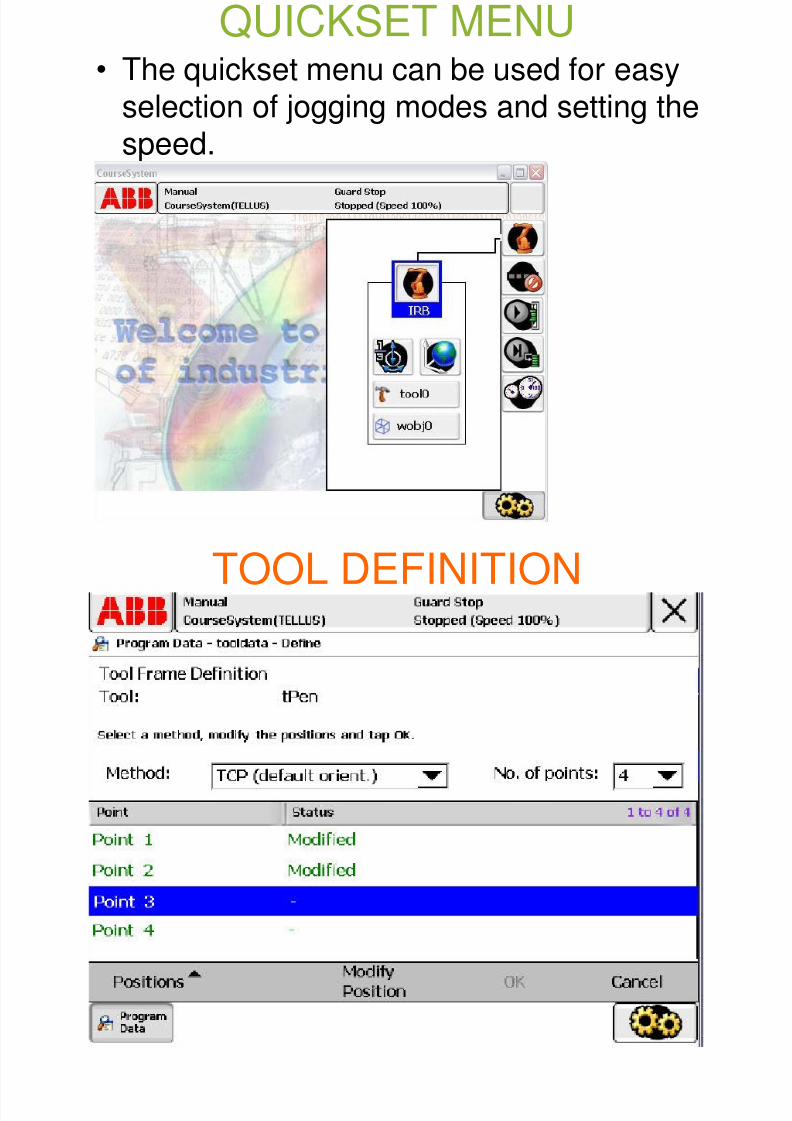
Q• The quickset menu can be used for easy
selection of jogging modes and setting the
speed.
TOOL DEFINITION
8/3/2019 Robotics Part3
http://slidepdf.com/reader/full/robotics-part3 70/87
TOOL DEFINITION
8/3/2019 Robotics Part3
http://slidepdf.com/reader/full/robotics-part3 71/87
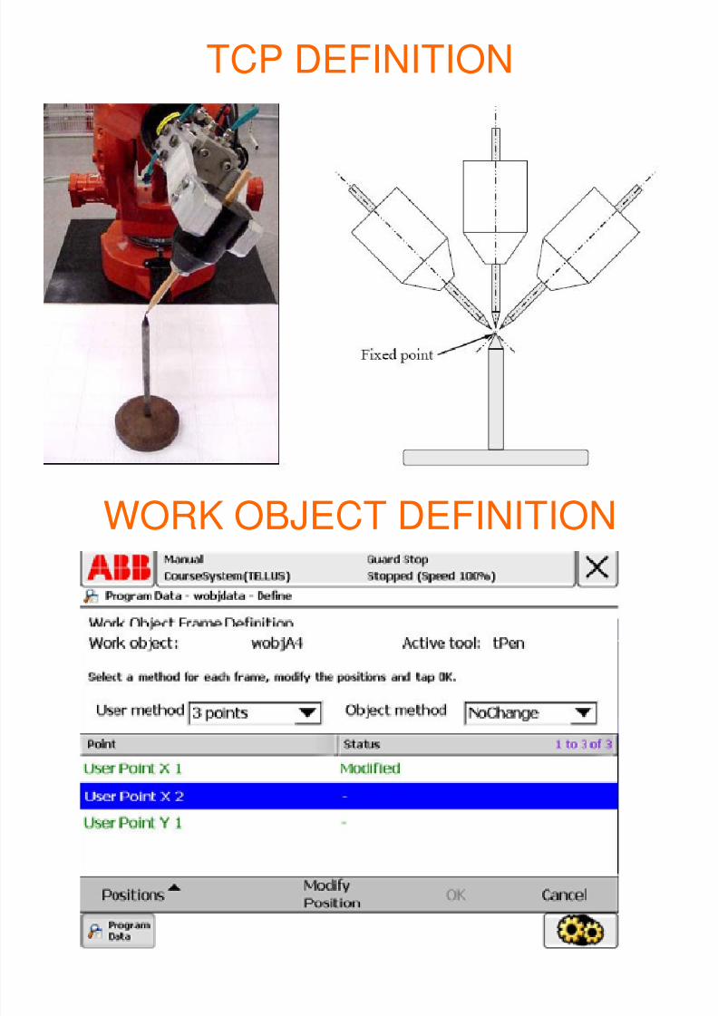
TCP DEFINITION
WORK OBJECT DEFINITION
8/3/2019 Robotics Part3
http://slidepdf.com/reader/full/robotics-part3 72/87
WORK OBJECT DEFINITION

8/3/2019 Robotics Part3
http://slidepdf.com/reader/full/robotics-part3 73/87
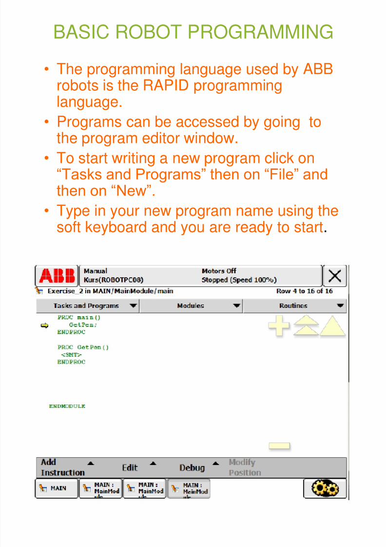
BASIC ROBOT PROGRAMMING
• The programming language used by ABBrobots is the RAPID programminglanguage.
• Programs can be accessed by going tothe program editor window.
• To start writing a new program click on“Tasks and Programs” then on “File” andthen on “New”.
• Type in your new program name using thesoft keyboard and you are ready to start.

8/3/2019 Robotics Part3
http://slidepdf.com/reader/full/robotics-part3 74/87
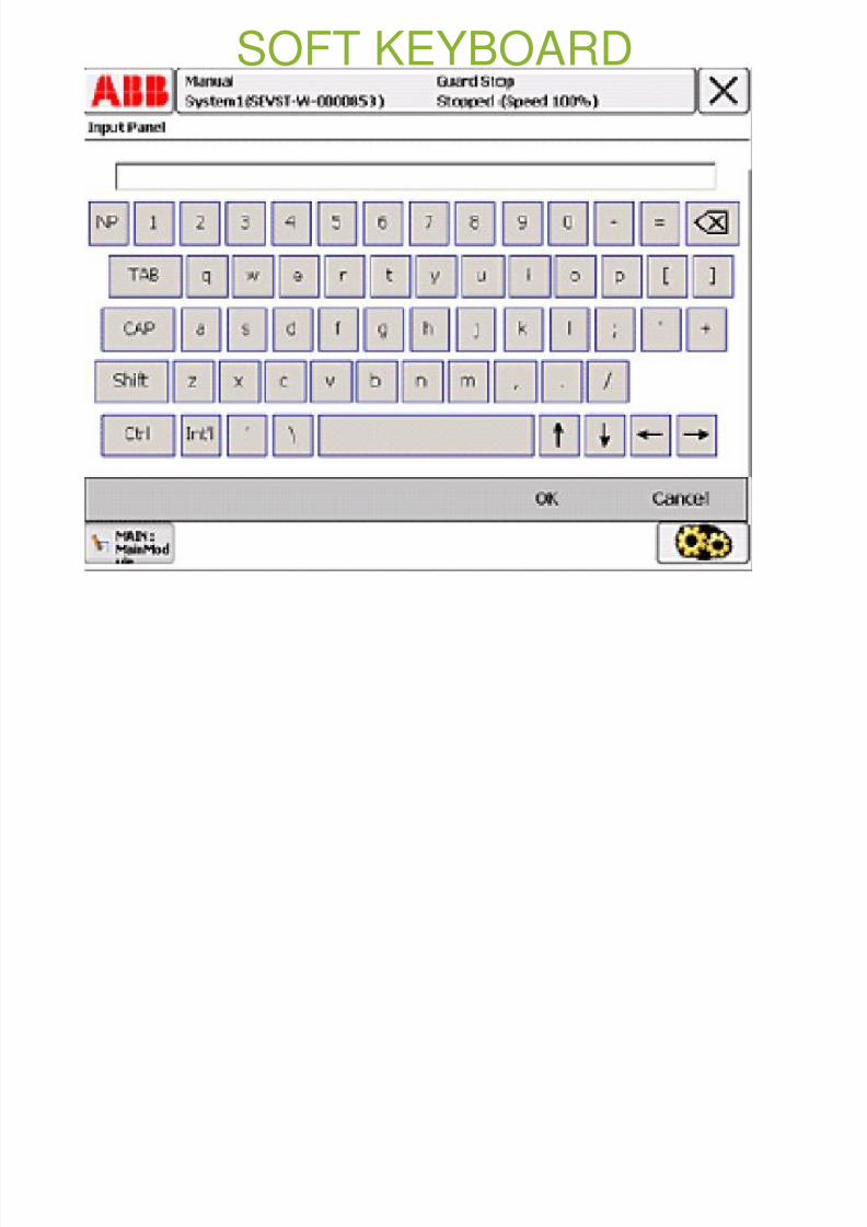
SOFT KEYBOARD

8/3/2019 Robotics Part3
http://slidepdf.com/reader/full/robotics-part3 75/87
SOFT KEYBOARD

8/3/2019 Robotics Part3
http://slidepdf.com/reader/full/robotics-part3 76/87
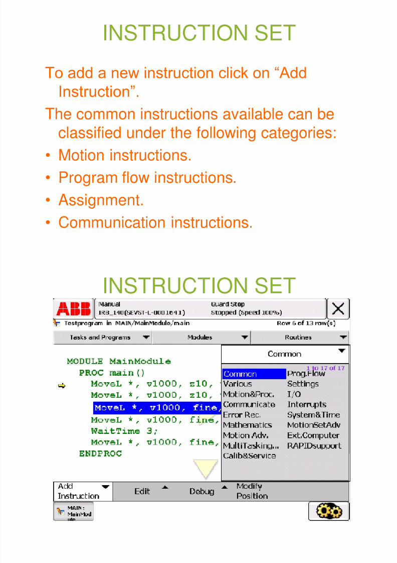
INSTRUCTION SET
To add a new instruction click on “AddInstruction”.
The common instructions available can be
classified under the following categories:
• Motion instructions.
• Program flow instructions.
• Assignment.
• Communication instructions.
INSTRUCTION SET

8/3/2019 Robotics Part3
http://slidepdf.com/reader/full/robotics-part3 77/87
INSTRUCTION SET
MOTION INSTRUCTIONS

8/3/2019 Robotics Part3
http://slidepdf.com/reader/full/robotics-part3 78/87
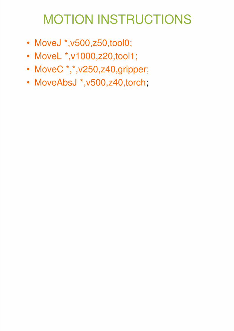
MOTION INSTRUCTIONS
• MoveJ *,v500,z50,tool0;
• MoveL *,v1000,z20,tool1;
• MoveC *,*,v250,z40,gripper;
• MoveAbsJ *,v500,z40,torch;
M J

8/3/2019 Robotics Part3
http://slidepdf.com/reader/full/robotics-part3 79/87
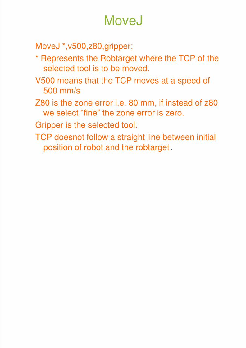
MoveJ
MoveJ *,v500,z80,gripper;
* Represents the Robtarget where the TCP of theselected tool is to be moved.
V500 means that the TCP moves at a speed of500 mm/s
Z80 is the zone error i.e. 80 mm, if instead of z80we select “fine” the zone error is zero.
Gripper is the selected tool.
TCP doesnot follow a straight line between initialposition of robot and the robtarget.
M L

8/3/2019 Robotics Part3
http://slidepdf.com/reader/full/robotics-part3 80/87
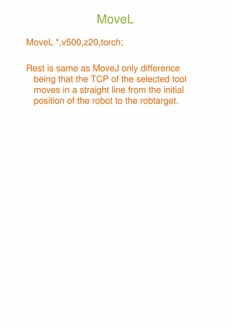
MoveL
MoveL *,v500,z20,torch;
Rest is same as MoveJ only differencebeing that the TCP of the selected toolmoves in a straight line from the initialposition of the robot to the robtarget.
M C

8/3/2019 Robotics Part3
http://slidepdf.com/reader/full/robotics-part3 81/87
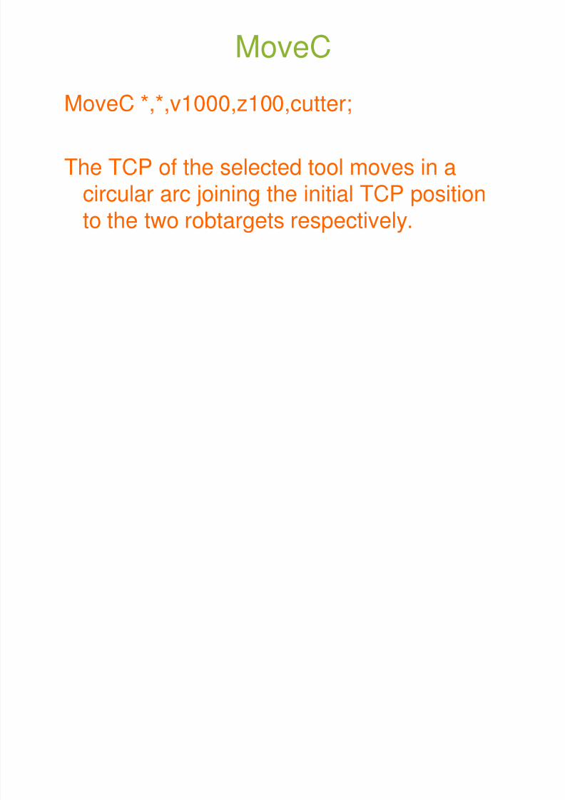
MoveC
MoveC *,*,v1000,z100,cutter;
The TCP of the selected tool moves in acircular arc joining the initial TCP positionto the two robtargets respectively.
M Ab J

8/3/2019 Robotics Part3
http://slidepdf.com/reader/full/robotics-part3 82/87
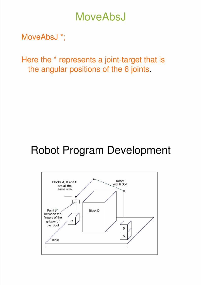
MoveAbsJ
MoveAbsJ *;
Here the * represents a joint-target that isthe angular positions of the 6 joints.
R b t P D l t

8/3/2019 Robotics Part3
http://slidepdf.com/reader/full/robotics-part3 83/87
Robot Program Development
Robot Program Development Process

8/3/2019 Robotics Part3
http://slidepdf.com/reader/full/robotics-part3 84/87
Robot Program Development Process
• Analyze and decompose the task into a series ofoperations on the objects involved, and specify theirorder.
• Identify and specify all the situations needed to programall the movements and actions of the robot.
• Identify any types of repeated actions or operations andspecify them as subroutines with parameters.
• Design and develop the complete robot program and itsdocumentation.
• Test and debug the program using a simulator of therobot and its work space.
• Test the program on the real robot.
I/O BOARDS

8/3/2019 Robotics Part3
http://slidepdf.com/reader/full/robotics-part3 85/87
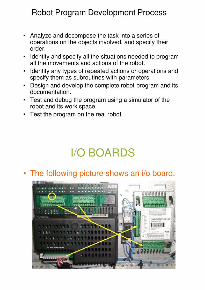
I/O BOARDS
• The following picture shows an i/o board.
UPDATE REV COUNTERS

8/3/2019 Robotics Part3
http://slidepdf.com/reader/full/robotics-part3 86/87
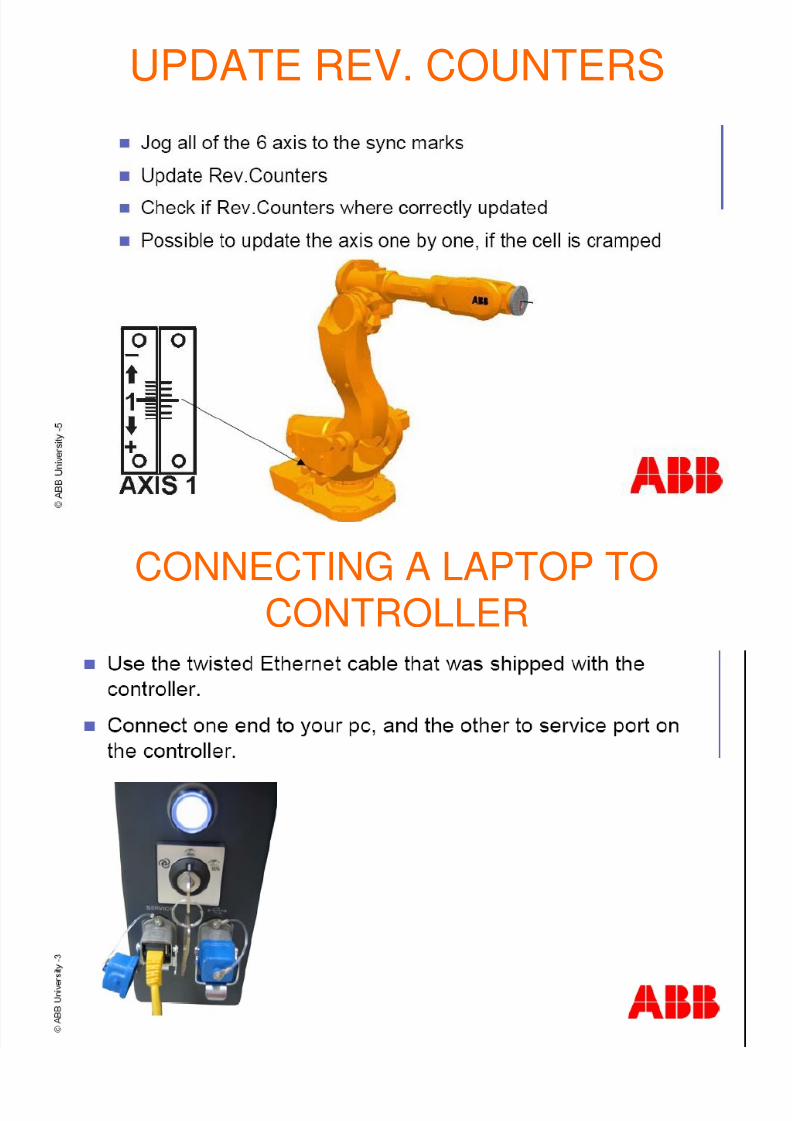
UPDATE REV. COUNTERS
CONNECTING A LAPTOP TO

8/3/2019 Robotics Part3
http://slidepdf.com/reader/full/robotics-part3 87/87
CONNECTING A LAPTOP TOCONTROLLER