Embed Size (px)
Citation preview

Engineered Products for Robotic ProductivityPinnacle Park • 1031 Goodworth Drive • Apex, NC 27539 USA • Tel: 919.772.0115 • Fax: 919.772.8259 • www.ati-ia.com • Email: [email protected]
Robotic Tool Changers QC-5 through QC-27
Manual
Document #: 9610-20-2254
Manual, Robotic Tool Changer, QC-5 through QC-27Document #9610-20-2254-08
Pinnacle Park • 1031 Goodworth Drive • Apex, NC 27539 USA • Tel: 919.772.0115 • Fax: 919.772.8259 • www.ati-ia.com • Email: [email protected] 2
ForewordThis manual contains basic information applicable to all ATI robotic Tool Changers. Certain models have their own manuals that contain more detailed information. Also, additional information about electrical, pneumatic, fluid, high-power, and high-current modules and other options are available in other manuals and documents.
Please contact ATI Industrial Automation with any questions concerning your particular model.
CAUTION: This manual describes the function, application, and safety considerations of this product. This manual must be read and understood before any attempt is made to install or operate the product, otherwise damage to the product or unsafe conditions may occur.
Information contained in this document is the property of ATI Industrial Automation, Inc. (ATI) and shall not be reproduced in whole or in part without prior written approval of ATI. The information herein is subject to change without notice. This manual is periodically revised to reflect and incorporate changes made to the product.
The information contained herein is confidential and reserved exclusively for the customers and authorized agents of ATI Industrial Automation and may not be divulged to any third party without prior written consent from ATI. No warranty including implied warranties is made with regard to accuracy of this document or fitness of this device for a particular application. ATI Industrial Automation shall not be liable for any errors contained in this document or for any incidental or consequential damages caused thereby. ATI Industrial Automation also reserves the right to make changes to this manual at any time without prior notice.
ATI assumes no responsibility for any errors or omissions in this document. Users’ critical evaluation of this document is welcomed.
Copyright by ATI Industrial Automation. All rights reserved.
How to Reach Us
Sale, Service and Information about ATI products:
ATI Industrial Automation 1031 Goodworth Drive Apex, NC 27539 USA www.ati-ia.com Tel: 919.772.0115 Fax: 919.772.8259 E-mail: [email protected]
Technical support and questions:Application Engineering Tel: 919.772.0115, Option 2, Option 2 Fax: 919.772.8259 E-mail: [email protected]
Manual, Robotic Tool Changer, QC-5 through QC-27Document #9610-20-2254-08
Pinnacle Park • 1031 Goodworth Drive • Apex, NC 27539 USA • Tel: 919.772.0115 • Fax: 919.772.8259 • www.ati-ia.com • Email: [email protected] 3
Table of ContentsForeword .......................................................................................................................................... 21. Safety ......................................................................................................................................... 8
1.1 ExplanationofNotifications ......................................................................................................... 8
1.2 General Safety Guidelines ............................................................................................................ 8
1.3 Safety Precautions ........................................................................................................................ 9
2. Product Overview ................................................................................................................... 102.1 Master Plate Assembly ............................................................................................................... 11
2.2 Tool Plate Assembly .................................................................................................................... 12
2.3 Master plate/Tool plate locking Mechanism ............................................................................. 13
2.4 Optional Sensor Interface Plate (SIP) ........................................................................................ 13
2.5 Optional Modules ........................................................................................................................ 14
3. Installation .............................................................................................................................. 143.1 Robot Interface Plates ................................................................................................................ 16
3.2 Master Plate Installation ............................................................................................................. 17
3.3 Master Plate Removal ................................................................................................................. 19
3.4 Tool Interface Plate ..................................................................................................................... 20
3.5 Tool Plate Installation ................................................................................................................. 21
3.6 Tool Plate Removal ..................................................................................................................... 21
3.7 Optional Module Installation ...................................................................................................... 223.7.1 QC-5 and QC-11 Simple Electrical Module Installation .................................................... 22
3.7.2 QC-5 and QC-11 Simple Electrical Module Removal ....................................................... 22
3.7.3 QC-5 and QC-11 Master Electrical Module Installation .................................................... 23
3.7.4 QC-5 and QC-11 Master Electrical Module Removal ....................................................... 23
3.7.5 QC-5 and QC-11 Tool Electrical Module Installation ........................................................ 24
3.7.6 QC-5 and QC-11 Tool Electrical Module Removal ........................................................... 24
3.7.7 QC-20, QC-21, and QC-27 Flat A Optional K Series Module Installation ......................... 25
3.7.8 QC-20, QC-21, and QC-27 Flat A Optional K Series Module Removal ............................ 25
3.7.9 QC-21 Flat B Optional Module Installation ....................................................................... 26
3.7.10 QC-21 Flat B Optional Module Removal .......................................................................... 27
3.8 Installing an Optional SIP ........................................................................................................... 273.8.1 QC-11 SIP Assembly Installation ...................................................................................... 27
3.8.2 QC-20 and QC-21 SIP Assembly Installation ................................................................... 30
3.9 Lock and Unlock Pneumatic and Valve Requirements ............................................................ 34
3.10 Electrical Connections ................................................................................................................ 353.10.1 PNP Type Lock and Unlock Sensors ................................................................................ 35
3.10.2 NPN Type Lock and Unlock Sensors ............................................................................... 36
Manual, Robotic Tool Changer, QC-5 through QC-27Document #9610-20-2254-08
Pinnacle Park • 1031 Goodworth Drive • Apex, NC 27539 USA • Tel: 919.772.0115 • Fax: 919.772.8259 • www.ati-ia.com • Email: [email protected] 4
4. Operation ................................................................................................................................ 374.1 Coupling Sequence ..................................................................................................................... 38
4.2 Fail-Safe Operation ..................................................................................................................... 38
4.3 Uncoupling Sequence ................................................................................................................. 39
4.4 ToolIdentification ........................................................................................................................ 39
4.5 Tool Storage Considerations ..................................................................................................... 40
5. Maintenance ............................................................................................................................ 415.1 Preventive Maintenance ............................................................................................................. 42
5.2 Cleaning and Lubrication of the Locking Mechanism and Alignment Pins ........................... 43
5.3 Optional Electrical Module Pin Block Inspection and Cleaning ............................................. 45
6. Troubleshooting and Service Procedures ........................................................................... 466.1 Troubleshooting .......................................................................................................................... 46
6.2 Service Procedures ..................................................................................................................... 476.2.1 QC-11 and QC-27 Proximity Sensor Adjustment, Test, or Replacement .......................... 47
6.2.2 QC-20 and QC-21 Proximity Sensor Adjustment, Test, or Replacement ......................... 50
6.2.3 Rubber Bushing Inspection and Replacement ................................................................. 53
6.2.4 QC-27M Alignment Pin Replacement ............................................................................... 54
6.2.5 Optional Electrical Module V-ring Seal Inspection and Replacement .............................. 55
7. Specifications ......................................................................................................................... 568. Serviceable Parts ................................................................................................................... 57
8.1 Models QC-5 Serviceable Parts ................................................................................................. 57
8.2 Models QC-11 Serviceable Parts ................................................................................................ 58
8.3 Models QC-20 PM5 Model Serviceable Parts ............................................................................ 59
8.4 Models QC-20 with 16 M5 X 0.8 Pass through Ports Serviceable Parts ................................. 60
8.5 Models QC-21 Serviceable Parts ............................................................................................... 61
8.6 Models QC-27 Serviceable Parts ............................................................................................... 62
9. Drawings ................................................................................................................................. 639.1 QC-5 Tool Changer with EA2 Module ........................................................................................ 63
9.2 QC-11 Tool Changer with A15 Module ....................................................................................... 64
9.3 QC-20 Tool Changer with K19 Module ...................................................................................... 65
9.4 QC-21 Tool Changer with K19 Module ...................................................................................... 66
9.5 QC-21 Euro Tool Changer ........................................................................................................... 67
9.6 QC-27 Tool Changer .................................................................................................................... 70
10. Terms and Conditions of Sale ............................................................................................... 73

Manual, Robotic Tool Changer, QC-5 through QC-27Document #9610-20-2254-08
Pinnacle Park • 1031 Goodworth Drive • Apex, NC 27539 USA • Tel: 919.772.0115 • Fax: 919.772.8259 • www.ati-ia.com • Email: [email protected] 5
Glossary of TermsTable 1.1—Tool Changer and Module Glossary
Term Definition
Bearing Race A steel ring in the Tool plate that is engaged by the locking balls during the coupling of the Tool Changer.
Cam A multi tapered sliding cylinder attached to the piston that forces the locking balls outward during the locking process.
Coupling The physical action of the locking the Master and Tool plates together. See Lock.
Cover Plate A protective closure plate on the standard Master assemblies which closes the pneumatic chamber.
Detection Shaft A threaded stem inserted into the robot side of the piston and functions as a target to actuate the Lock/Unlock sensors.
Electrical Module Utility modules that pass electrical power and signals through the Master and Tool modules to the end-effector.
End-Effector Tool used by the robot to perform a particular operation or function.
Fluid Module Utility modules that pass fluids through the Master and Tool modules to the end-effector.
High Current Module Utility modules that pass electrical power through the Master and Tool modules to the end-effector.
Interface Plate (IP) An optional customized component that is used to adapt a Tool Changer to the user’s robot or tooling.
LockThe lock air pressure that is provided to the Master plate locking mechanism to force the cam to press the locking balls against the bearing race and lock the Master and Tool plates together.
Lock Port A pneumatic port on the Master plate through which air pressure is supplied to Lock the Master plate to the Tool plate.
Lock Sensor A proximity sensor that detects the position of the pneumatically actuated piston when it is in the locked or missed tool position.
Locked An output signal provided by a proximity sensor that indicates the coupling mechanism is in the Locked position.
Locking BallsHardened steel ball bearings used in the fail-safe locking mechanism. The locking balls are forced outward by the cam against the bearing race to pull the Master and Tool plates together.
Locking Mechanism
A manual, pneumatic or electrical driven device that draws the Master and Tool plates together and secures them in a fail-safe locked condition until the mechanism is unlocked. The locking mechanism consists of locking balls, cam, ball cage, bearing race, and either an lever, pneumatic cylinder, or an electric motor.
L/U Lock/Unlock sensing capability that allows the customer to determine the state of the master assembly locking mechanism.
Master plate The half of the Tool Changer that is mounted to a robot. The Master plate contains the locking mechanism.
Moment The applied force multiplied by the distance it is from a point.
No-Touch™ A design feature of all ATI Tool Changer products that allows the Master plate and Tool plate to couple without physical contact prior to locking.
Piston A cylinder located in the Master plate that actuates the locking mechanism.

Manual, Robotic Tool Changer, QC-5 through QC-27Document #9610-20-2254-08
Pinnacle Park • 1031 Goodworth Drive • Apex, NC 27539 USA • Tel: 919.772.0115 • Fax: 919.772.8259 • www.ati-ia.com • Email: [email protected] 6
Table 1.1—Tool Changer and Module GlossaryTerm Definition
Pneumatic Module Utility modules that pass air or vacuum through the Master and Tool modules to the end-effector.
Sensor Plate A cover plate for the back side of the Master plate that seals the pneumatic chamber and provides mounting points for the Lock/Unlock switches.
Servo Module Utility modules that pass electrical power and servo signals through the Master and Tool modules to the end-effector equipped with a servo motor.
Sensor Interface Plate SIP (SIP)
Used to adapt the Tool Changer Master to the customer-supplied robot. An interface plate that contains sensors that determine the state (Locked/Unlocked/No Tool) of the Master plate.
Tool plate The half of the Tool Changer to which various tools or end-effectors are mounted. Tool Stand A stand that holds the Tools not being used by the robot.
Trip Dog A physical device used to activate a mechanical switch, which is used in the tool stand Interlock circuit.
Uncoupling The physical action of the unlocking the Master and Tool plates. See Unlock. Unlatch The output supplied to the ATI Master module to uncouple the Tool Changer.
UnlockThe unlock air pressure provided to the Master plate locking mechanism that forces the cam to release the locking balls from the bearing race and allows the Master and Tool plates to be separated.
Unlocked An output signal provided by a proximity sensor, indicating that the coupling mechanism is in the Unlocked position.
Unlock Port Pneumatic port on the Master plate through which air pressure is supplied to Unlock the Master plate from the Tool plate.
Unlock Sensor A proximity sensor that detects the position of the pneumatically actuated piston when it is in the unlocked position.

Manual, Robotic Tool Changer, QC-5 through QC-27Document #9610-20-2254-08
Pinnacle Park • 1031 Goodworth Drive • Apex, NC 27539 USA • Tel: 919.772.0115 • Fax: 919.772.8259 • www.ati-ia.com • Email: [email protected] 7
1. SafetyThe safety section describes general safety guidelines to be followed with this product, explanations of the notifications found in this manual, and safety precautions that apply to the product. More specific notifications are imbedded within the sections of the manual where they apply.
1.1 ExplanationofNotificationsThe following notifications are specific to the product(s) covered by this manual. It is expected that the user heed all notifications from the robot manufacturer and/or the manufacturers of other components used in the installation.
DANGER: Notification of information or instructions that if not followed will result in death or serious injury. The notification provides information about the nature of the hazardous situation, the consequences of not avoiding the hazard, and the method for avoiding the situation.
WARNING: Notification of information or instructions that if not followed could result in death or serious injury. The notification provides information about the nature of the hazardous situation, the consequences of not avoiding the hazard, and the method for avoiding the situation.
CAUTION: Notification of information or instructions that if not followed could result in moderate injury or will cause damage to equipment. The notification provides information about the nature of the hazardous situation, the consequences of not avoiding the hazard, and the method for avoiding the situation.
NOTICE: Notification of specific information or instructions about maintaining, operating, installing, or setting up the product that if not followed could result in damage to equipment. The notification can emphasize, but is not limited to: specific grease types, best operating practices, and maintenance tips.
1.2 General Safety GuidelinesPrior to purchase and installation, the customer should verify that the Tool Changer selected is rated for the maximum loads and moments expected during operation. Refer to product specifications section in each module of this manual or contact ATI for assistance. Particular attention should be paid to dynamic loads caused by robot acceleration and deceleration. These forces can be many times the value of static forces in high acceleration or deceleration situations.The customer is responsible for ensuring that the area between the Master and Tool sides is clear of foreign objects during mating and subsequent coupling. Failure to do so may result in serious injury to personnel.
DANGER: The gap between the Master and Tool sides is a pinch point. All personnel should be prevented from placing any part of their body or clothing in the gap, especially during actuation of the locking mechanism.
The customer is responsible for understanding the function of the Tool Changer and implementing the proper fasteners and/or software to operate the Tool Changer safely. The Tool Changer should be controlled such that there is no chance of locking or unlocking in a position that would endanger personnel and/or equipment. If the Tool Changer is specified with Lock/Unlock (L/U) and Ready-to-Lock (RTL) sensing capability, the status should be monitored and interlocks applied to prevent injury to personnel and equipment.All pneumatic fittings and tubing must be capable of withstanding the repetitive motions of the application without failing. The routing of electrical and pneumatic lines must minimize the possibility of stress/strain, kinking, rupture, etc. Failure of critical electrical or pneumatic lines to function properly may result in injury to personnel and equipment.All electrical power, pneumatic and fluid circuits should be disconnected during servicing.
Manual, Robotic Tool Changer, QC-5 through QC-27Document #9610-20-2254-08
Pinnacle Park • 1031 Goodworth Drive • Apex, NC 27539 USA • Tel: 919.772.0115 • Fax: 919.772.8259 • www.ati-ia.com • Email: [email protected] 8
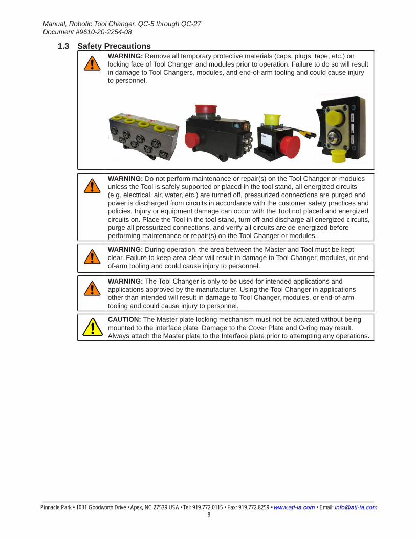
1.3 Safety PrecautionsWARNING: Remove all temporary protective materials (caps, plugs, tape, etc.) on locking face of Tool Changer and modules prior to operation. Failure to do so will result in damage to Tool Changers, modules, and end-of-arm tooling and could cause injury to personnel.
WARNING: Do not perform maintenance or repair(s) on the Tool Changer or modules unless the Tool is safely supported or placed in the tool stand, all energized circuits (e.g. electrical, air, water, etc.) are turned off, pressurized connections are purged and power is discharged from circuits in accordance with the customer safety practices and policies. Injury or equipment damage can occur with the Tool not placed and energized circuits on. Place the Tool in the tool stand, turn off and discharge all energized circuits, purge all pressurized connections, and verify all circuits are de-energized before performing maintenance or repair(s) on the Tool Changer or modules.
WARNING: During operation, the area between the Master and Tool must be kept clear. Failure to keep area clear will result in damage to Tool Changer, modules, or end-of-arm tooling and could cause injury to personnel.
WARNING: The Tool Changer is only to be used for intended applications and applications approved by the manufacturer. Using the Tool Changer in applications other than intended will result in damage to Tool Changer, modules, or end-of-arm tooling and could cause injury to personnel.
CAUTION: The Master plate locking mechanism must not be actuated without being mounted to the interface plate. Damage to the Cover Plate and O-ring may result. Always attach the Master plate to the Interface plate prior to attempting any operations.
Manual, Robotic Tool Changer, QC-5 through QC-27Document #9610-20-2254-08
Pinnacle Park • 1031 Goodworth Drive • Apex, NC 27539 USA • Tel: 919.772.0115 • Fax: 919.772.8259 • www.ati-ia.com • Email: [email protected] 9
2. Product OverviewThe Tool Changer provides flexibility to robot applications by allowing the robot to change customer tooling (e.g., grippers, vacuum cup tooling, pneumatic and electric motors, weld guns, etc.) automatically. The Tool Changer consists of a Master plate and a Tool plate. The Master plate is attached to a robot, while end-effectors such as grippers, material handlers, etc. are attached to one or more Tool plates.
The Master plate locks to the Tool plate with a pneumatically driven locking mechanism. This locking mechanism uses a patented, multi-tapered cam with ball locking technology and a patented fail-safe mechanism.
The robot can be programmed to select the desired customer tooling by coupling the Master plate to the Tool plate attached to the tooling. Electrical signals, pneumatic power, and fluids can be transferred to the customer tooling through the Master plate and Tool plate by optional modules. See the respective manuals for these options for more details.
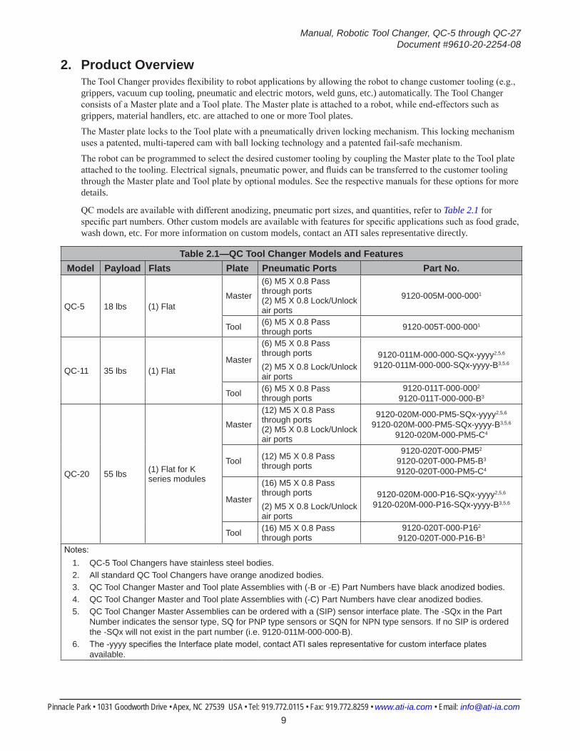
QC models are available with different anodizing, pneumatic port sizes, and quantities, refer to Table 2.1 for specific part numbers. Other custom models are available with features for specific applications such as food grade, wash down, etc. For more information on custom models, contact an ATI sales representative directly.
Table 2.1—QC Tool Changer Models and FeaturesModel Payload Flats Plate Pneumatic Ports Part No.
QC-5 18 lbs (1) FlatMaster
(6) M5 X 0.8 Pass through ports (2) M5 X 0.8 Lock/Unlock air ports
9120-005M-000-0001
Tool (6) M5 X 0.8 Pass through ports 9120-005T-000-0001
QC-11 35 lbs (1) FlatMaster
(6) M5 X 0.8 Pass through ports(2) M5 X 0.8 Lock/Unlock air ports
9120-011M-000-000-SQx-yyyy2,5,6 9120-011M-000-000-SQx-yyyy-B3,5,6
Tool (6) M5 X 0.8 Pass through ports
9120-011T-000-0002 9120-011T-000-000-B3
QC-20 55 lbs (1) Flat for K series modules
Master
(12) M5 X 0.8 Pass through ports (2) M5 X 0.8 Lock/Unlock air ports
9120-020M-000-PM5-SQx-yyyy2,5,6 9120-020M-000-PM5-SQx-yyyy-B3,5,6
9120-020M-000-PM5-C4
Tool (12) M5 X 0.8 Pass through ports
9120-020T-000-PM52 9120-020T-000-PM5-B3 9120-020T-000-PM5-C4
Master
(16) M5 X 0.8 Pass through ports(2) M5 X 0.8 Lock/Unlock air ports
9120-020M-000-P16-SQx-yyyy2,5,6 9120-020M-000-P16-SQx-yyyy-B3,5,6
Tool (16) M5 X 0.8 Pass through ports
9120-020T-000-P162 9120-020T-000-P16-B3
Notes: 1. QC-5 Tool Changers have stainless steel bodies.2. All standard QC Tool Changers have orange anodized bodies.3. QC Tool Changer Master and Tool plate Assemblies with (-B or -E) Part Numbers have black anodized bodies.4. QC Tool Changer Master and Tool plate Assemblies with (-C) Part Numbers have clear anodized bodies.5. QC Tool Changer Master Assemblies can be ordered with a (SIP) sensor interface plate. The -SQx in the Part
Number indicates the sensor type, SQ for PNP type sensors or SQN for NPN type sensors. If no SIP is ordered the -SQx will not exist in the part number (i.e. 9120-011M-000-000-B).
6. The -yyyy specifies the Interface plate model, contact ATI sales representative for custom interface plates available.
Manual, Robotic Tool Changer, QC-5 through QC-27Document #9610-20-2254-08
Pinnacle Park • 1031 Goodworth Drive • Apex, NC 27539 USA • Tel: 919.772.0115 • Fax: 919.772.8259 • www.ati-ia.com • Email: [email protected] 10
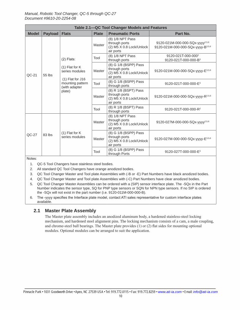
Table 2.1—QC Tool Changer Models and FeaturesModel Payload Flats Plate Pneumatic Ports Part No.
QC-21 55 lbs
(2) Flats: (1) Flat for K series modules (1) Flat for J16 mounting pattern (with adapter plate)
Master
(8) 1/8 NPT Pass through ports (2) M5 X 0.8 Lock/Unlock air ports
9120-021M-000-000-SQx-yyyy2,5,6 9120-021M-000-000-SQx-yyyy-B3,5,6
Tool (8) 1/8 NPT Pass through ports
9120-021T-000-0002 9120-021T-000-000-B3
Master
(8) G 1/8 (BSPP) Pass through ports (2) M5 X 0.8 Lock/Unlock air ports
9120-021M-000-000-SQx-yyyy-E3,5,6
Tool (8) G 1/8 (BSPP) Pass through ports 9120-021T-000-000-E3
Master
(8) R 1/8 (BSPT) Pass through ports (2) M5 X 0.8 Lock/Unlock air ports
9120-021M-000-000-SQx-yyyy-R2,5,6
Tool (8) R 1/8 (BSPT) Pass through ports 9120-021T-000-000-R2
QC-27 83 lbs (1) Flat for K series modules
Master
(8) 1/8 NPT Pass through ports (2) M5 X 0.8 Lock/Unlock air ports
9120-027M-000-000-SQx-yyyy2,5,6
Master
(8) G 1/8 (BSPP) Pass through ports (2) M5 X 0.8 Lock/Unlock air ports
9120-027M-000-000-SQx-yyyy-E3,5,6
Tool (8) G 1/8 (BSPP) Pass through Ports 9120-027T-000-000-E3
Notes: 1. QC-5 Tool Changers have stainless steel bodies.2. All standard QC Tool Changers have orange anodized bodies.3. QC Tool Changer Master and Tool plate Assemblies with (-B or -E) Part Numbers have black anodized bodies.4. QC Tool Changer Master and Tool plate Assemblies with (-C) Part Numbers have clear anodized bodies.5. QC Tool Changer Master Assemblies can be ordered with a (SIP) sensor interface plate. The -SQx in the Part
Number indicates the sensor type, SQ for PNP type sensors or SQN for NPN type sensors. If no SIP is ordered the -SQx will not exist in the part number (i.e. 9120-011M-000-000-B).
6. The -yyyy specifies the Interface plate model, contact ATI sales representative for custom interface plates available.
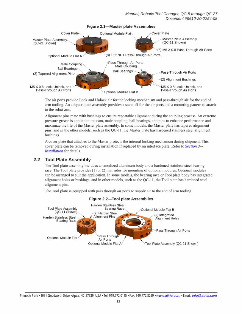
2.1 Master Plate AssemblyThe Master plate assembly includes an anodized aluminum body, a hardened stainless-steel locking mechanism, and hardened steel alignment pins. The locking mechanism consists of a cam, a male coupling, and chrome-steel ball bearings. The Master plate provides (1) or (2) flat sides for mounting optional modules. Optional modules can be arranged to suit the application.
Manual, Robotic Tool Changer, QC-5 through QC-27Document #9610-20-2254-08
Pinnacle Park • 1031 Goodworth Drive • Apex, NC 27539 USA • Tel: 919.772.0115 • Fax: 919.772.8259 • www.ati-ia.com • Email: [email protected] 11
Figure 2.1—Master plate AssembliesOptional Module Flat Cover PlateCover Plate
(6) M5 X 0.8 Pass-Through Air Ports
Optional Module Flat A (8) 1/8" NPT Pass-Through Air Ports
Master Plate Assembly(QC-11 Shown)
Master Plate Assembly(QC-21 Shown)
(2) Tapered Alignment Pins
Male CouplingBall Bearings
Pass-Through Air Ports
Male CouplingBall Bearings
(2) Alignment Bushings
Pass-Through Air Ports
M5 X 0.8 Lock, Unlock, andPass-Through Air PortsOptional Module Flat B
M5 X 0.8 Lock, Unlock, andPass-Through Air Ports
The air ports provide Lock and Unlock air for the locking mechanism and pass-through air for the end of arm tooling. An adapter plate assembly provides a standoff for the air ports and a mounting pattern to attach to the robot arm.Alignment pins mate with bushings to ensure repeatable alignment during the coupling process. An extreme pressure grease is applied to the cam, male coupling, ball bearings, and pins to enhance performance and maximize the life of the Master plate assembly. In some models, the Master plate has tapered alignment pins, and in the other models, such as the QC-11, the Master plate has hardened stainless steel alignment bushings.A cover plate that attaches to the Master protects the internal locking mechanism during shipment. This cover plate can be removed during installation if replaced by an interface plate. Refer to Section 3—Installation for details.
2.2 Tool Plate AssemblyThe Tool plate assembly includes an anodized aluminum body and a hardened stainless-steel bearing race. The Tool plate provides (1) or (2) flat sides for mounting of optional modules. Optional modules can be arranged to suit the application. In some models, the bearing race or Tool plate body has integrated alignment holes or bushings, and in other models, such as the QC-11, the Tool plate has hardened steel alignment pins. The Tool plate is equipped with pass through air ports to supply air to the end of arm tooling.
Figure 2.2—Tool plate Assemblies
Optional Module Flat B
Optional Module Flat A
Optional Module Flat
Tool Plate Assembly(QC-11 Shown)
Tool Plate Assembly (QC-21 Shown)
(2) Harden Steel Alignment PinsHarden Stainless Steel
Bearing Race
Harden Stainless Steel Bearing Race
(2) Integrated Alignment Holes
Pass Through Air Ports
Pass Through Air Ports
Manual, Robotic Tool Changer, QC-5 through QC-27Document #9610-20-2254-08
Pinnacle Park • 1031 Goodworth Drive • Apex, NC 27539 USA • Tel: 919.772.0115 • Fax: 919.772.8259 • www.ati-ia.com • Email: [email protected] 12
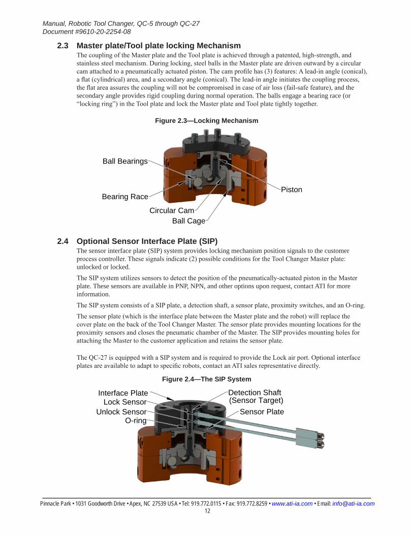
2.3 Master plate/Tool plate locking MechanismThe coupling of the Master plate and the Tool plate is achieved through a patented, high-strength, and stainless steel mechanism. During locking, steel balls in the Master plate are driven outward by a circular cam attached to a pneumatically actuated piston. The cam profile has (3) features: A lead-in angle (conical), a flat (cylindrical) area, and a secondary angle (conical). The lead-in angle initiates the coupling process, the flat area assures the coupling will not be compromised in case of air loss (fail-safe feature), and the secondary angle provides rigid coupling during normal operation. The balls engage a bearing race (or “locking ring”) in the Tool plate and lock the Master plate and Tool plate tightly together.
Figure 2.3—Locking Mechanism
PistonBearing Race
Circular CamBall Cage
Ball Bearings
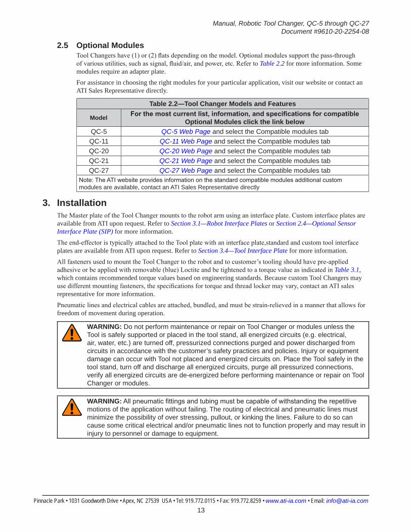
2.4 Optional Sensor Interface Plate (SIP)The sensor interface plate (SIP) system provides locking mechanism position signals to the customer process controller. These signals indicate (2) possible conditions for the Tool Changer Master plate: unlocked or locked.The SIP system utilizes sensors to detect the position of the pneumatically-actuated piston in the Master plate. These sensors are available in PNP, NPN, and other options upon request, contact ATI for more information.The SIP system consists of a SIP plate, a detection shaft, a sensor plate, proximity switches, and an O-ring.The sensor plate (which is the interface plate between the Master plate and the robot) will replace the cover plate on the back of the Tool Changer Master. The sensor plate provides mounting locations for the proximity sensors and closes the pneumatic chamber of the Master. The SIP provides mounting holes for attaching the Master to the customer application and retains the sensor plate.
The QC-27 is equipped with a SIP system and is required to provide the Lock air port. Optional interface plates are available to adapt to specific robots, contact an ATI sales representative directly.
Figure 2.4—The SIP System
Detection Shaft (Sensor Target)
Unlock SensorLock Sensor
Interface Plate
O-ringSensor Plate
Manual, Robotic Tool Changer, QC-5 through QC-27Document #9610-20-2254-08
Pinnacle Park • 1031 Goodworth Drive • Apex, NC 27539 USA • Tel: 919.772.0115 • Fax: 919.772.8259 • www.ati-ia.com • Email: [email protected] 13
2.5 Optional ModulesTool Changers have (1) or (2) flats depending on the model. Optional modules support the pass-through of various utilities, such as signal, fluid/air, and power, etc. Refer to Table 2.2 for more information. Some modules require an adapter plate.For assistance in choosing the right modules for your particular application, visit our website or contact an ATI Sales Representative directly.
Table 2.2—Tool Changer Models and Features
Model Forthemostcurrentlist,information,andspecificationsforcompatibleOptional Modules click the link below
QC-5 QC-5 Web Page and select the Compatible modules tabQC-11 QC-11 Web Page and select the Compatible modules tabQC-20 QC-20 Web Page and select the Compatible modules tabQC-21 QC-21 Web Page and select the Compatible modules tabQC-27 QC-27 Web Page and select the Compatible modules tab
Note: The ATI website provides information on the standard compatible modules additional custom modules are available, contact an ATI Sales Representative directly
3. InstallationThe Master plate of the Tool Changer mounts to the robot arm using an interface plate. Custom interface plates are available from ATI upon request. Refer to Section 3.1—Robot Interface Plates or Section 2.4—Optional Sensor Interface Plate (SIP) for more information.
The end-effector is typically attached to the Tool plate with an interface plate,standard and custom tool interface plates are available from ATI upon request. Refer to Section 3.4—Tool Interface Plate for more information.
All fasteners used to mount the Tool Changer to the robot and to customer’s tooling should have pre-applied adhesive or be applied with removable (blue) Loctite and be tightened to a torque value as indicated in Table 3.1, which contains recommended torque values based on engineering standards. Because custom Tool Changers may use different mounting fasteners, the specifications for torque and thread locker may vary, contact an ATI sales representative for more information.
Pneumatic lines and electrical cables are attached, bundled, and must be strain-relieved in a manner that allows for freedom of movement during operation.
WARNING: Do not perform maintenance or repair on Tool Changer or modules unless the Tool is safely supported or placed in the tool stand, all energized circuits (e.g. electrical, air, water, etc.) are turned off, pressurized connections purged and power discharged from circuits in accordance with the customer’s safety practices and policies. Injury or equipment damage can occur with Tool not placed and energized circuits on. Place the Tool safely in the tool stand, turn off and discharge all energized circuits, purge all pressurized connections, verify all energized circuits are de-energized before performing maintenance or repair on Tool Changer or modules.
WARNING: All pneumatic fittings and tubing must be capable of withstanding the repetitive motions of the application without failing. The routing of electrical and pneumatic lines must minimize the possibility of over stressing, pullout, or kinking the lines. Failure to do so can cause some critical electrical and/or pneumatic lines not to function properly and may result in injury to personnel or damage to equipment.
Manual, Robotic Tool Changer, QC-5 through QC-27Document #9610-20-2254-08
Pinnacle Park • 1031 Goodworth Drive • Apex, NC 27539 USA • Tel: 919.772.0115 • Fax: 919.772.8259 • www.ati-ia.com • Email: [email protected] 14
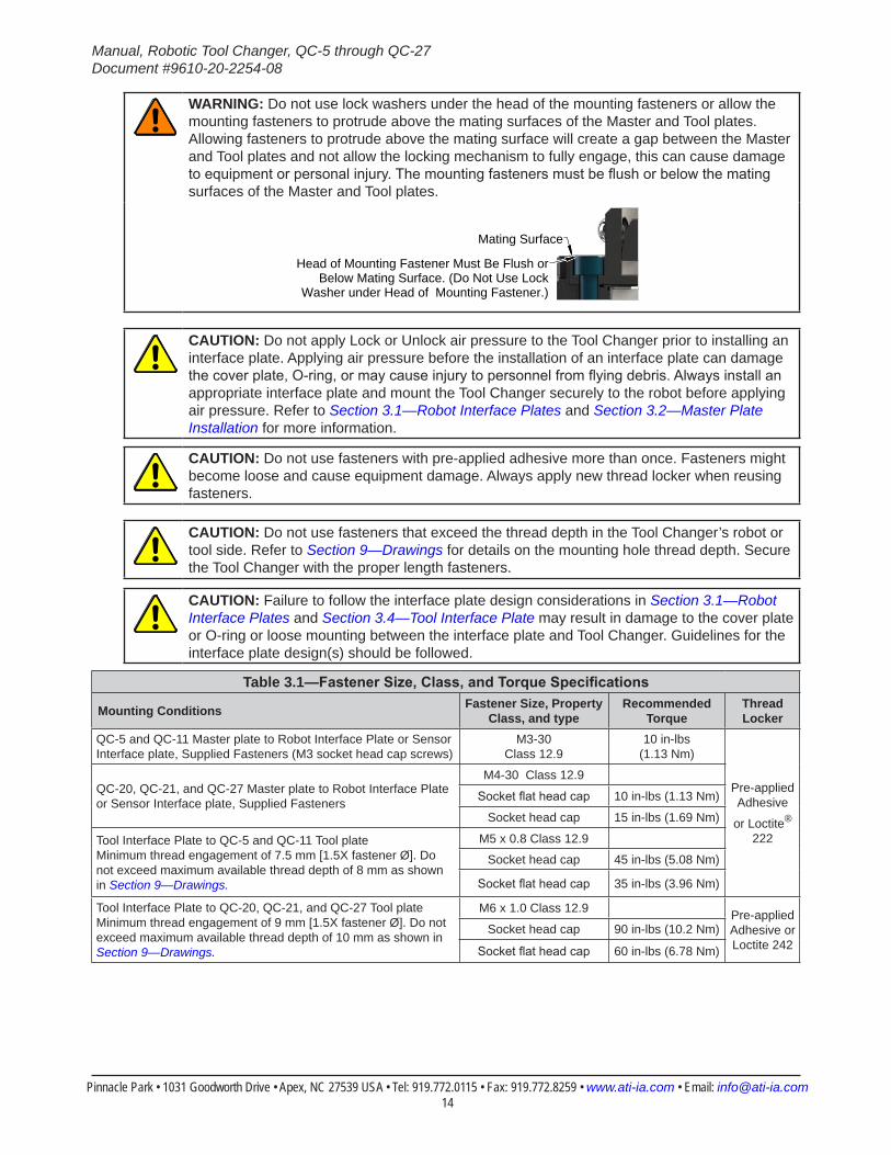
WARNING: Do not use lock washers under the head of the mounting fasteners or allow the mounting fasteners to protrude above the mating surfaces of the Master and Tool plates. Allowing fasteners to protrude above the mating surface will create a gap between the Master and Tool plates and not allow the locking mechanism to fully engage, this can cause damage to equipment or personal injury. The mounting fasteners must be flush or below the mating surfaces of the Master and Tool plates.
Head of Mounting Fastener Must Be Flush orBelow Mating Surface. (Do Not Use Lock
Washer under Head of Mounting Fastener.)
Mating Surface
CAUTION: Do not apply Lock or Unlock air pressure to the Tool Changer prior to installing an interface plate. Applying air pressure before the installation of an interface plate can damage the cover plate, O-ring, or may cause injury to personnel from flying debris. Always install an appropriate interface plate and mount the Tool Changer securely to the robot before applying air pressure. Refer to Section 3.1—Robot Interface Plates and Section 3.2—Master Plate Installation for more information.
CAUTION: Do not use fasteners with pre-applied adhesive more than once. Fasteners might become loose and cause equipment damage. Always apply new thread locker when reusing fasteners.
CAUTION: Do not use fasteners that exceed the thread depth in the Tool Changer’s robot or tool side. Refer to Section 9—Drawings for details on the mounting hole thread depth. Secure the Tool Changer with the proper length fasteners.
CAUTION: Failure to follow the interface plate design considerations in Section 3.1—Robot Interface Plates and Section 3.4—Tool Interface Plate may result in damage to the cover plate or O-ring or loose mounting between the interface plate and Tool Changer. Guidelines for the interface plate design(s) should be followed.
Table 3.1—FastenerSize,Class,andTorqueSpecifications
Mounting Conditions Fastener Size, Property Class, and type
Recommended Torque
Thread Locker
QC-5 and QC-11 Master plate to Robot Interface Plate or Sensor Interface plate, Supplied Fasteners (M3 socket head cap screws)
M3-30 Class 12.9
10 in-lbs (1.13 Nm)
Pre-applied Adhesive
or Loctite® 222
QC-20, QC-21, and QC-27 Master plate to Robot Interface Plate or Sensor Interface plate, Supplied Fasteners
M4-30 Class 12.9
Socket flat head cap 10 in-lbs (1.13 Nm)
Socket head cap 15 in-lbs (1.69 Nm)
Tool Interface Plate to QC-5 and QC-11 Tool plate Minimum thread engagement of 7.5 mm [1.5X fastener Ø]. Do not exceed maximum available thread depth of 8 mm as shown in Section 9—Drawings.
M5 x 0.8 Class 12.9
Socket head cap 45 in-lbs (5.08 Nm)
Socket flat head cap 35 in-lbs (3.96 Nm)
Tool Interface Plate to QC-20, QC-21, and QC-27 Tool plate Minimum thread engagement of 9 mm [1.5X fastener Ø]. Do not exceed maximum available thread depth of 10 mm as shown in Section 9—Drawings.
M6 x 1.0 Class 12.9 Pre-applied Adhesive or Loctite 242
Socket head cap 90 in-lbs (10.2 Nm)
Socket flat head cap 60 in-lbs (6.78 Nm)
Manual, Robotic Tool Changer, QC-5 through QC-27Document #9610-20-2254-08
Pinnacle Park • 1031 Goodworth Drive • Apex, NC 27539 USA • Tel: 919.772.0115 • Fax: 919.772.8259 • www.ati-ia.com • Email: [email protected] 15
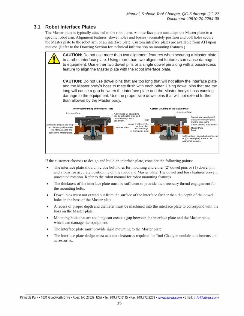
3.1 Robot Interface PlatesThe Master plate is typically attached to the robot arm. An interface plate can adapt the Master plate to a specific robot arm. Alignment features (dowel holes and bosses) accurately position and bolt holes secure the Master plate to the robot arm or an interface plate. Custom interface plates are available from ATI upon request. (Refer to the Drawing Section for technical information on mounting features.)
CAUTION: Do not use more than two alignment features when securing a Master plate to a robot interface plate. Using more than two alignment features can cause damage to equipment. Use either two dowel pins or a single dowel pin along with a boss/recess feature to align the Master plate with the robot interface plate.
CAUTION: Do not use dowel pins that are too long that will not allow the interface plate and the Master body’s boss to mate flush with each other. Using dowel pins that are too long will cause a gap between the interface plate and the Master body’s boss causing damage to the equipment. Use the proper size dowel pins that will not extend further than allowed by the Master body.
Interface Plate
Dowel pins that are too long can cause a gap between
the interface plate and boss in the Master plate.
A boss and (2) dowel pinscan be difficult to align andcause damage to the
Master Plate
Incorrect Mounting of the Master Plate
equipment.Correct size dowel pin(s)allows the interface plate and the boss in the Master plate to mount flush.
Interface Plate
Master PlateBoss
Flush
A gap is between theinterface plate
and the flange of the Master plate.
Note: A dowel pin and a boss/recessor ((2) dowel pins) are used asalignment features.
Correct Mounting of the Master Plate
If the customer chooses to design and build an interface plate, consider the following points:• The interface plate should include bolt holes for mounting and either (2) dowel pins or (1) dowel pin
and a boss for accurate positioning on the robot and Master plate. The dowel and boss features prevent unwanted rotation. Refer to the robot manual for robot mounting features.
• The thickness of the interface plate must be sufficient to provide the necessary thread engagement for the mounting bolts.
• Dowel pins must not extend out from the surface of the interface farther than the depth of the dowel holes in the boss of the Master plate.
• A recess of proper depth and diameter must be machined into the interface plate to correspond with the boss on the Master plate.
• Mounting bolts that are too long can create a gap between the interface plate and the Master plate, which can damage the equipment.
• The interface plate must provide rigid mounting to the Master plate.
• The interface plate design must account clearances required for Tool Changer module attachments and accessories.
Manual, Robotic Tool Changer, QC-5 through QC-27Document #9610-20-2254-08
Pinnacle Park • 1031 Goodworth Drive • Apex, NC 27539 USA • Tel: 919.772.0115 • Fax: 919.772.8259 • www.ati-ia.com • Email: [email protected] 16
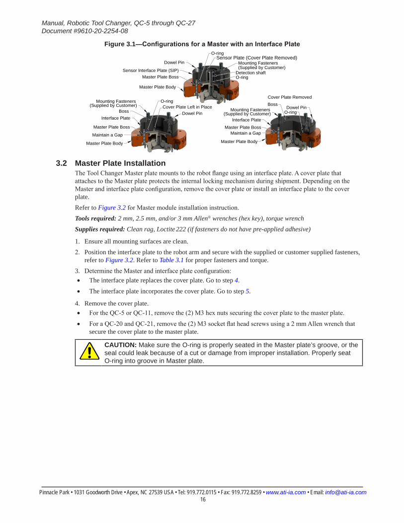
Figure 3.1—ConfigurationsforaMasterwithanInterfacePlate
Sensor Interface Plate (SIP)
Master Plate Body
Master Plate Boss
Sensor Plate (Cover Plate Removed)O-ring
Detection shaftO-ring
Dowel Pin Mounting Fasteners(Supplied by Customer)
Interface Plate
Master Plate Body
Master Plate Boss
O-ring
Maintain a Gap
BossDowel PinMounting Fasteners
(Supplied by Customer)
Cover Plate Removed
Interface Plate
Master Plate Boss
Master Plate Body
Maintain a Gap
Cover Plate Left in PlaceO-ring
Dowel PinBoss
Mounting Fasteners(Supplied by Customer)
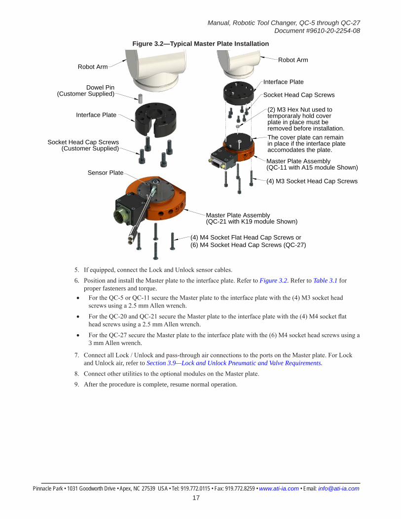
3.2 Master Plate InstallationThe Tool Changer Master plate mounts to the robot flange using an interface plate. A cover plate that attaches to the Master plate protects the internal locking mechanism during shipment. Depending on the Master and interface plate configuration, remove the cover plate or install an interface plate to the cover plate.Refer to Figure 3.2 for Master module installation instruction.Tools required: 2 mm, 2.5 mm, and/or 3 mm Allen® wrenches (hex key), torque wrenchSupplies required: Clean rag, Loctite 222 (if fasteners do not have pre-applied adhesive)
1. Ensure all mounting surfaces are clean.2. Position the interface plate to the robot arm and secure with the supplied or customer supplied fasteners,
refer to Figure 3.2. Refer to Table 3.1 for proper fasteners and torque.3. Determine the Master and interface plate configuration:• The interface plate replaces the cover plate. Go to step 4.
• The interface plate incorporates the cover plate. Go to step 5.
4. Remove the cover plate.• For the QC-5 or QC-11, remove the (2) M3 hex nuts securing the cover plate to the master plate.
• For a QC-20 and QC-21, remove the (2) M3 socket flat head screws using a 2 mm Allen wrench that secure the cover plate to the master plate.
CAUTION: Make sure the O-ring is properly seated in the Master plate’s groove, or the seal could leak because of a cut or damage from improper installation. Properly seat O-ring into groove in Master plate.
Manual, Robotic Tool Changer, QC-5 through QC-27Document #9610-20-2254-08
Pinnacle Park • 1031 Goodworth Drive • Apex, NC 27539 USA • Tel: 919.772.0115 • Fax: 919.772.8259 • www.ati-ia.com • Email: [email protected] 17
Figure 3.2—Typical Master Plate Installation
Robot Arm
Interface Plate
Master Plate Assembly(QC-21 with K19 module Shown)
Socket Head Cap Screws(Customer Supplied)
(4) M4 Socket Flat Head Cap Screws or(6) M4 Socket Head Cap Screws (QC-27)
Dowel Pin(Customer Supplied)
Sensor Plate(4) M3 Socket Head Cap Screws
Robot Arm
Interface Plate
Master Plate Assembly(QC-11 with A15 module Shown)
Socket Head Cap Screws
The cover plate can remainin place if the interface plateaccomodates the plate.
(2) M3 Hex Nut used to temporaraly hold cover plate in place must be removed before installation.
5. If equipped, connect the Lock and Unlock sensor cables.6. Position and install the Master plate to the interface plate. Refer to Figure 3.2. Refer to Table 3.1 for
proper fasteners and torque.• For the QC-5 or QC-11 secure the Master plate to the interface plate with the (4) M3 socket head
screws using a 2.5 mm Allen wrench.
• For the QC-20 and QC-21 secure the Master plate to the interface plate with the (4) M4 socket flat head screws using a 2.5 mm Allen wrench.
• For the QC-27 secure the Master plate to the interface plate with the (6) M4 socket head screws using a 3 mm Allen wrench.
7. Connect all Lock / Unlock and pass-through air connections to the ports on the Master plate. For Lock and Unlock air, refer to Section 3.9—Lock and Unlock Pneumatic and Valve Requirements.
8. Connect other utilities to the optional modules on the Master plate.9. After the procedure is complete, resume normal operation.

Manual, Robotic Tool Changer, QC-5 through QC-27Document #9610-20-2254-08
Pinnacle Park • 1031 Goodworth Drive • Apex, NC 27539 USA • Tel: 919.772.0115 • Fax: 919.772.8259 • www.ati-ia.com • Email: [email protected] 18
3.3 Master Plate RemovalRefer to Figure 3.2 for Master module removal instructions.Tools required: 2.5 mm or 3 mm Allen wrench (hex key)
1. Place the Tool in a secure location.2. Uncouple the Master and Tool plates.3. Turn off and de-energize all energized circuits (e.g. electrical, air, water, etc.).4. Disconnect all utilities (e.g. electrical, air, water, etc.).5. Disconnect the Lock and Unlock sensor cables.6. Remove the Master plate from the interface plate.• For a QC-5 or QC-11, remove the (4) M3 socket head cap screws securing the Master plate to the
interface plate.
• For a QC-20 or QC-21, remove the (4) M4 socket flat head cap screws securing the Master plate to the interface plate.
• For a QC-27 remove the (6) M4 socket head cap screws securing the Master plate to the interface plate.
Manual, Robotic Tool Changer, QC-5 through QC-27Document #9610-20-2254-08
Pinnacle Park • 1031 Goodworth Drive • Apex, NC 27539 USA • Tel: 919.772.0115 • Fax: 919.772.8259 • www.ati-ia.com • Email: [email protected] 19
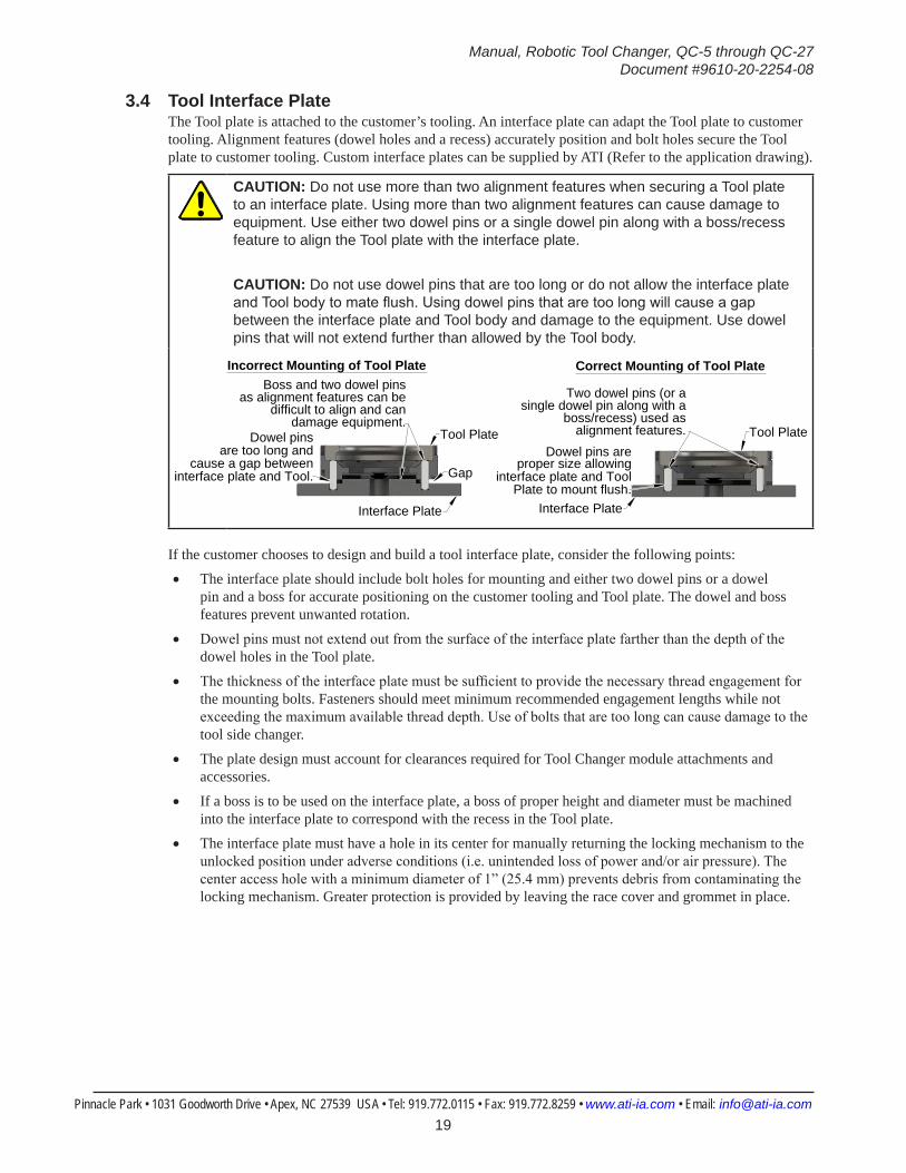
3.4 Tool Interface PlateThe Tool plate is attached to the customer’s tooling. An interface plate can adapt the Tool plate to customer tooling. Alignment features (dowel holes and a recess) accurately position and bolt holes secure the Tool plate to customer tooling. Custom interface plates can be supplied by ATI (Refer to the application drawing).
CAUTION: Do not use more than two alignment features when securing a Tool plate to an interface plate. Using more than two alignment features can cause damage to equipment. Use either two dowel pins or a single dowel pin along with a boss/recess feature to align the Tool plate with the interface plate.
CAUTION: Do not use dowel pins that are too long or do not allow the interface plate and Tool body to mate flush. Using dowel pins that are too long will cause a gap between the interface plate and Tool body and damage to the equipment. Use dowel pins that will not extend further than allowed by the Tool body.
Tool Plate
Interface Plate
Dowel pins areproper size allowing
interface plate and ToolPlate to mount flush.
Two dowel pins (or a
boss/recess) used asalignment features.
Correct Mounting of Tool Plate
Tool Plate
Interface Plate
Dowel pinsare too long and
cause a gap betweeninterface plate and Tool.
Boss and two dowel pinsas alignment features can be
difficult to align and candamage equipment.
Gap
Incorrect Mounting of Tool Plate
single dowel pin along with a
If the customer chooses to design and build a tool interface plate, consider the following points:• The interface plate should include bolt holes for mounting and either two dowel pins or a dowel
pin and a boss for accurate positioning on the customer tooling and Tool plate. The dowel and boss features prevent unwanted rotation.
• Dowel pins must not extend out from the surface of the interface plate farther than the depth of the dowel holes in the Tool plate.
• The thickness of the interface plate must be sufficient to provide the necessary thread engagement for the mounting bolts. Fasteners should meet minimum recommended engagement lengths while not exceeding the maximum available thread depth. Use of bolts that are too long can cause damage to the tool side changer.
• The plate design must account for clearances required for Tool Changer module attachments and accessories.
• If a boss is to be used on the interface plate, a boss of proper height and diameter must be machined into the interface plate to correspond with the recess in the Tool plate.
• The interface plate must have a hole in its center for manually returning the locking mechanism to the unlocked position under adverse conditions (i.e. unintended loss of power and/or air pressure). The center access hole with a minimum diameter of 1” (25.4 mm) prevents debris from contaminating the locking mechanism. Greater protection is provided by leaving the race cover and grommet in place.
Manual, Robotic Tool Changer, QC-5 through QC-27Document #9610-20-2254-08
Pinnacle Park • 1031 Goodworth Drive • Apex, NC 27539 USA • Tel: 919.772.0115 • Fax: 919.772.8259 • www.ati-ia.com • Email: [email protected] 20
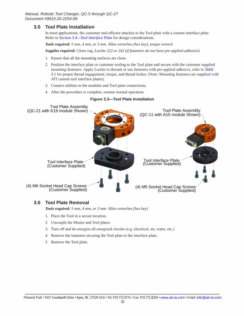
3.5 Tool Plate InstallationIn most applications, the customer end-effector attaches to the Tool plate with a custom interface plate. Refer to Section 3.4—Tool Interface Plate for design considerations.Tools required: 5 mm, 4 mm, or 3 mm Allen wrenches (hex key), torque wrenchSupplies required: Clean rag, Loctite 222 or 242 (if fasteners do not have pre-applied adhesive)
1. Ensure that all the mounting surfaces are clean.2. Position the interface plate or customer tooling to the Tool plate and secure with the customer supplied
mounting fasteners. Apply Loctite to threads or use fasteners with pre-applied adhesive, refer to Table 3.1 for proper thread engagement, torque, and thread locker. (Note: Mounting fasteners are supplied with ATI custom tool interface plates).
3. Connect utilities to the modules and Tool plate connections.4. After the procedure is complete, resume normal operation.
Figure 3.3—Tool Plate Installation
(4) M6 Socket Head Cap Screws
Tool Interface Plate
Tool Plate Assembly(QC-21 with K19 module Shown)
Tool Interface Plate
(4) M5 Socket Head Cap Screws
Tool Plate Assembly(QC-11 with A15 module Shown)
(Customer Supplied) (Customer Supplied)
(Customer Supplied) (Customer Supplied)
3.6 Tool Plate RemovalTools required: 5 mm, 4 mm, or 3 mm Allen wrenches (hex key)
1. Place the Tool in a secure location.2. Uncouple the Master and Tool plates.3. Turn off and de-energize all energized circuits (e.g. electrical, air, water, etc.).4. Remove the fasteners securing the Tool plate to the interface plate.5. Remove the Tool plate.
Manual, Robotic Tool Changer, QC-5 through QC-27Document #9610-20-2254-08
Pinnacle Park • 1031 Goodworth Drive • Apex, NC 27539 USA • Tel: 919.772.0115 • Fax: 919.772.8259 • www.ati-ia.com • Email: [email protected] 21
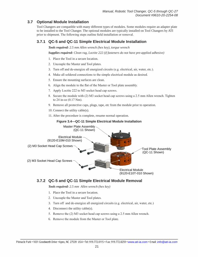
3.7 Optional Module InstallationTool Changers are compatible with many different types of modules. Some modules require an adapter plate to be installed to the Tool Changer. The optional modules are typically installed on Tool Changers by ATI prior to shipment. The following steps outline field installation or removal.
3.7.1 QC-5 and QC-11 Simple Electrical Module InstallationTools required: 2.5 mm Allen wrench (hex key), torque wrenchSupplies required: Clean rag, Loctite 222 (if fasteners do not have pre-applied adhesive)
1. Place the Tool in a secure location.2. Uncouple the Master and Tool plates.3. Turn off and de-energize all energized circuits (e.g. electrical, air, water, etc.).4. Make all soldered connections to the simple electrical module as desired.5. Ensure the mounting surfaces are clean.6. Align the module to the flat of the Master or Tool plate assembly.7. Apply Loctite 222 to M3 socket head cap screws.8. Secure the module with (2) M3 socket head cap screws using a 2.5 mm Allen wrench. Tighten
to 24 in-oz (0.17 Nm).9. Remove all protective caps, plugs, tape, etc from the module prior to operation.10. Connect the utility cable(s).11. After the procedure is complete, resume normal operation.
Figure 3.4—QC-11 Simple Electrical Module Installation
(2) M3 Socket Head Cap ScrewsTool Plate Assembly(QC-11 Shown)
Master Plate Assembly(QC-11 Shown)
(2) M3 Socket Head Cap Screws
Electrical Module(9120-E10M-010 Shown)
Electrical Module(9120-E10T-010 Shown)
3.7.2 QC-5 and QC-11 Simple Electrical Module RemovalTools required: 2.5 mm Allen wrench (hex key)
1. Place the Tool in a secure location.2. Uncouple the Master and Tool plates.3. Turn off and de-energize all energized circuits (e.g. electrical, air, water, etc.)4. Disconnect the utility cable(s).5. Remove the (2) M3 socket head cap screws using a 2.5 mm Allen wrench.6. Remove the module from the Master or Tool plate.
Manual, Robotic Tool Changer, QC-5 through QC-27Document #9610-20-2254-08
Pinnacle Park • 1031 Goodworth Drive • Apex, NC 27539 USA • Tel: 919.772.0115 • Fax: 919.772.8259 • www.ati-ia.com • Email: [email protected] 22
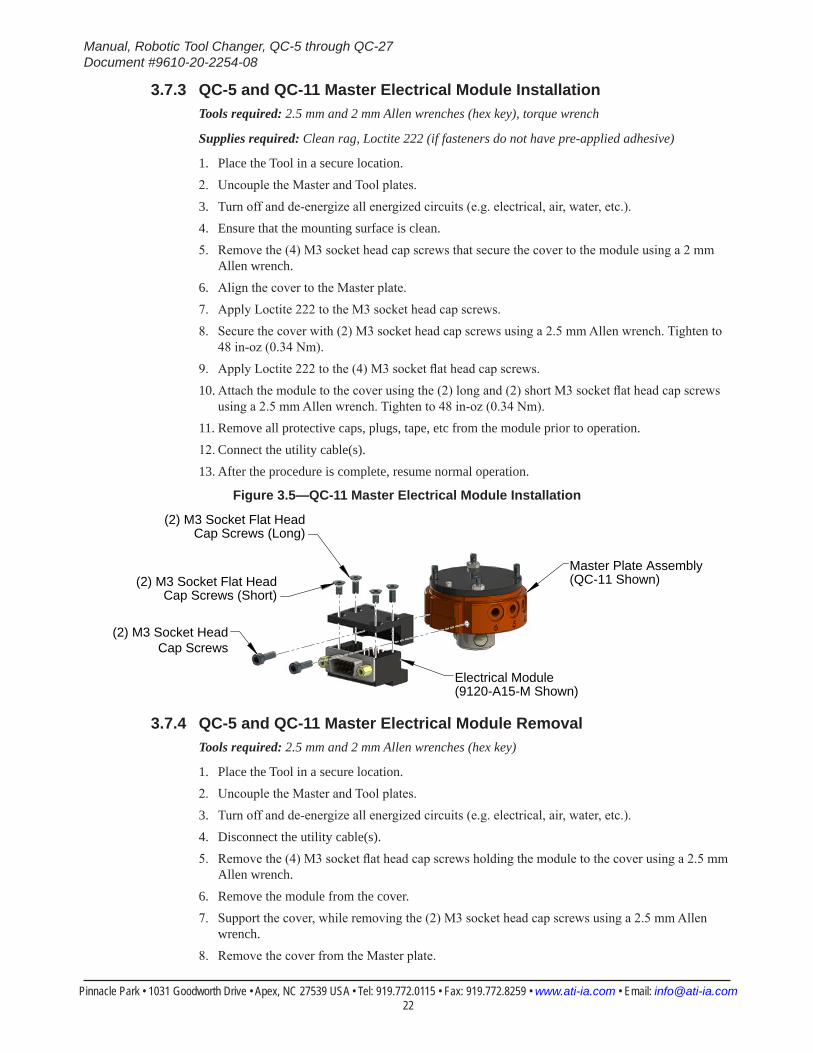
3.7.3 QC-5 and QC-11 Master Electrical Module InstallationTools required: 2.5 mm and 2 mm Allen wrenches (hex key), torque wrench
Supplies required: Clean rag, Loctite 222 (if fasteners do not have pre-applied adhesive)
1. Place the Tool in a secure location.2. Uncouple the Master and Tool plates.3. Turn off and de-energize all energized circuits (e.g. electrical, air, water, etc.).4. Ensure that the mounting surface is clean.5. Remove the (4) M3 socket head cap screws that secure the cover to the module using a 2 mm
Allen wrench.6. Align the cover to the Master plate.7. Apply Loctite 222 to the M3 socket head cap screws.8. Secure the cover with (2) M3 socket head cap screws using a 2.5 mm Allen wrench. Tighten to
48 in-oz (0.34 Nm).9. Apply Loctite 222 to the (4) M3 socket flat head cap screws.10. Attach the module to the cover using the (2) long and (2) short M3 socket flat head cap screws
using a 2.5 mm Allen wrench. Tighten to 48 in-oz (0.34 Nm).11. Remove all protective caps, plugs, tape, etc from the module prior to operation.12. Connect the utility cable(s).13. After the procedure is complete, resume normal operation.
Figure 3.5—QC-11 Master Electrical Module Installation
(2) M3 Socket Head Cap Screws
Master Plate Assembly(QC-11 Shown)
(2) M3 Socket Flat Head Cap Screws (Long)
Electrical Module(9120-A15-M Shown)
(2) M3 Socket Flat Head Cap Screws (Short)
3.7.4 QC-5 and QC-11 Master Electrical Module RemovalTools required: 2.5 mm and 2 mm Allen wrenches (hex key)
1. Place the Tool in a secure location.2. Uncouple the Master and Tool plates.3. Turn off and de-energize all energized circuits (e.g. electrical, air, water, etc.).4. Disconnect the utility cable(s).5. Remove the (4) M3 socket flat head cap screws holding the module to the cover using a 2.5 mm
Allen wrench.6. Remove the module from the cover.7. Support the cover, while removing the (2) M3 socket head cap screws using a 2.5 mm Allen
wrench.8. Remove the cover from the Master plate.

Manual, Robotic Tool Changer, QC-5 through QC-27Document #9610-20-2254-08
Pinnacle Park • 1031 Goodworth Drive • Apex, NC 27539 USA • Tel: 919.772.0115 • Fax: 919.772.8259 • www.ati-ia.com • Email: [email protected] 23
3.7.5 QC-5 and QC-11 Tool Electrical Module InstallationTools required: 2.5 mm Allen wrench (hex key), 3/16” wrench, torque wrench
Supplies required: Clean rag, Loctite 222 (if fasteners do not have pre-applied adhesive)
1. Place the Tool in a secure location.2. Uncouple the Master and Tool plates.3. Turn off and de-energize all energized circuits (e.g. electrical, air, water, etc.).4. Ensure the mounting surfaces are clean.5. Remove the (2) screw locks that secure the connector to the module.6. Carefully remove the connector to expose the mounting screws.7. Align the module to the Tool plate.8. Apply Loctite 222 to M3 socket head cap screws.9. Secure the module with (2) M3 socket head cap screws using a 2.5 mm Allen wrench. Tighten
to 24 in-oz (0.17 Nm).10. Apply Loctite 222 to the (2) screw locks.11. Attach the connector to the module using the (2) screw locks using a 3/16” wrench. Tighten to
24 in-oz (0.17 Nm).12. Remove all protective caps, plugs, tape, etc from the module prior to operation.13. Connect the utility cable(s).14. After the procedure is complete, resume normal operation.
Figure 3.6—QC-11 Tool Electrical Module Installation
(2) M3 Socket Head Cap Screws
Tool Plate Assembly(QC-11 Shown)
Connector
Electrical Module(9120-A15-T Shown)
(2) Screw Locks
3.7.6 QC-5 and QC-11 Tool Electrical Module RemovalTools required: 2.5 mm Allen wrench (hex key), 3/16” wrench
1. Place the Tool in a secure location.2. Uncouple the Master and Tool plates.3. Turn off and de-energized all energized circuits (e.g. electrical, air, water, etc.).4. Disconnect the utility cable(s).5. Remove the (2) screw locks that secure the connector to the module using a 3/16” wrench.6. Carefully remove the connector to expose the mounting screws.7. Remove the (2) M3 socket head cap screws that attach the module to the Tool plate using a 2.5
mm Allen wrench.8. Remove the module from the Tool plate.
Manual, Robotic Tool Changer, QC-5 through QC-27Document #9610-20-2254-08
Pinnacle Park • 1031 Goodworth Drive • Apex, NC 27539 USA • Tel: 919.772.0115 • Fax: 919.772.8259 • www.ati-ia.com • Email: [email protected] 24
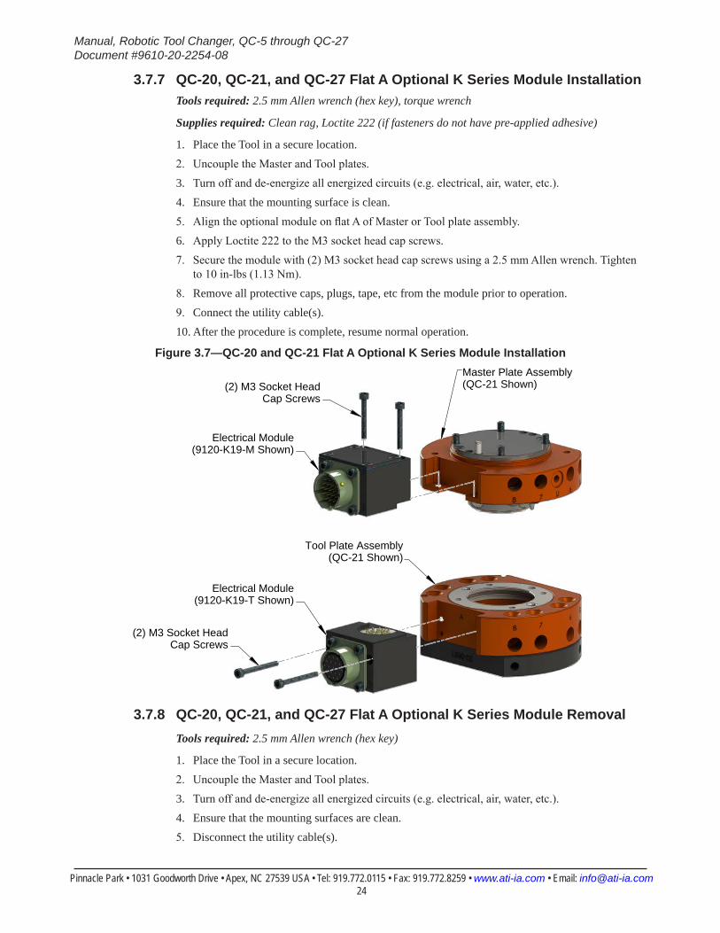
3.7.7 QC-20, QC-21, and QC-27 Flat A Optional K Series Module InstallationTools required: 2.5 mm Allen wrench (hex key), torque wrench
Supplies required: Clean rag, Loctite 222 (if fasteners do not have pre-applied adhesive)
1. Place the Tool in a secure location.2. Uncouple the Master and Tool plates.3. Turn off and de-energize all energized circuits (e.g. electrical, air, water, etc.).4. Ensure that the mounting surface is clean.5. Align the optional module on flat A of Master or Tool plate assembly.6. Apply Loctite 222 to the M3 socket head cap screws.7. Secure the module with (2) M3 socket head cap screws using a 2.5 mm Allen wrench. Tighten
to 10 in-lbs (1.13 Nm).8. Remove all protective caps, plugs, tape, etc from the module prior to operation.9. Connect the utility cable(s).10. After the procedure is complete, resume normal operation.
Figure 3.7—QC-20 and QC-21 Flat A Optional K Series Module Installation
(2) M3 Socket Head Cap Screws
Tool Plate Assembly(QC-21 Shown)
Master Plate Assembly(QC-21 Shown)
(2) M3 Socket Head Cap Screws
Electrical Module(9120-K19-M Shown)
Electrical Module(9120-K19-T Shown)
3.7.8 QC-20, QC-21, and QC-27 Flat A Optional K Series Module RemovalTools required: 2.5 mm Allen wrench (hex key)
1. Place the Tool in a secure location.2. Uncouple the Master and Tool plates.3. Turn off and de-energize all energized circuits (e.g. electrical, air, water, etc.).4. Ensure that the mounting surfaces are clean.5. Disconnect the utility cable(s).
Manual, Robotic Tool Changer, QC-5 through QC-27Document #9610-20-2254-08
Pinnacle Park • 1031 Goodworth Drive • Apex, NC 27539 USA • Tel: 919.772.0115 • Fax: 919.772.8259 • www.ati-ia.com • Email: [email protected] 25
6. Remove the (2) M3 socket head cap screws securing the module to the Tool Changer using a 2.5 mm Allen wrench. Note: For the module on the Master, the Master plate may have to be removed refer to Section 3.3—Master Plate Removal.
7. Remove the module from the Master or Tool plate.
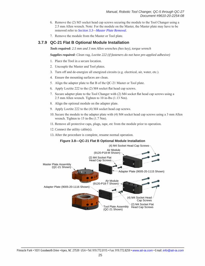
3.7.9 QC-21 Flat B Optional Module InstallationTools required: 2.5 mm and 3 mm Allen wrenches (hex key), torque wrench
Supplies required: Clean rag, Loctite 222 (if fasteners do not have pre-applied adhesive)
1. Place the Tool in a secure location.2. Uncouple the Master and Tool plates.3. Turn off and de-energize all energized circuits (e.g. electrical, air, water, etc.).4. Ensure the mounting surfaces are clean.5. Align the adapter plate to flat B of the QC-21 Master or Tool plate.6. Apply Loctite 222 to the (2) M4 socket flat head cap screws.7. Secure adapter plate to the Tool Changer with (2) M4 socket flat head cap screws using a
2.5 mm Allen wrench. Tighten to 10 in-lbs (1.13 Nm).8. Align the optional module on the adapter plate.9. Apply Loctite 222 to the (4) M4 socket head cap screws.10. Secure the module to the adapter plate with (4) M4 socket head cap screws using a 3 mm Allen
wrench. Tighten to 15 in-lbs (1.7 Nm).11. Remove all protective caps, plugs, tape, etc from the module prior to operation.12. Connect the utility cable(s).13. After the procedure is complete, resume normal operation.
Figure 3.8—QC-21 Flat B Optional Module Installation
Tool Plate Assembly(QC-21 Shown)
Master Plate Assembly(QC-21 Shown)
(4) M4 Socket Head Cap Screws
(4) M4 Socket Head Cap Screws
(2) M4 Socket FlatHead Cap Screws
(2) M4 Socket FlatHead Cap Screws
Air Module(9120-P18-M Shown)
Air Module(9120-P18-T Shown)
Adapter Plate (9005-20-1115 Shown)
Adapter Plate (9005-20-1116 Shown)
Manual, Robotic Tool Changer, QC-5 through QC-27Document #9610-20-2254-08
Pinnacle Park • 1031 Goodworth Drive • Apex, NC 27539 USA • Tel: 919.772.0115 • Fax: 919.772.8259 • www.ati-ia.com • Email: [email protected] 26
3.7.10 QC-21 Flat B Optional Module RemovalTools required: 2.5 mm and 3 mm Allen wrenches (hex key)
1. Place the Tool in a secure location.2. Uncouple the Master and Tool plates.3. Turn off and de-energize all energized circuits (e.g. electrical, air, water, etc.).4. Disconnect the utility cable(s).5. Remove the (4) M4 socket head cap screws using a 3 mm Allen wrench. 6. Remove the module from the adapter plate.7. Remove the (2) M4 socket flat head cap screws securing the adapter plate to the Master or Tool
plate using a 2.5 mm Allen wrench.8. Remove the adapter plate.
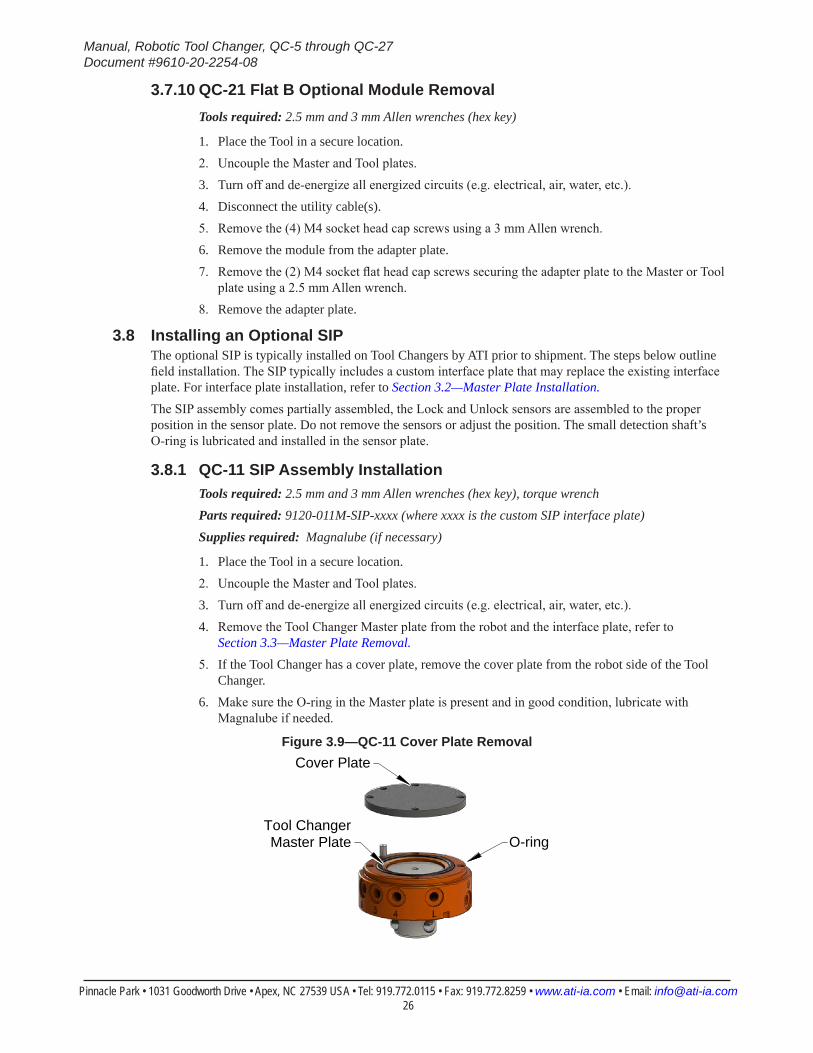
3.8 Installing an Optional SIPThe optional SIP is typically installed on Tool Changers by ATI prior to shipment. The steps below outline field installation. The SIP typically includes a custom interface plate that may replace the existing interface plate. For interface plate installation, refer to Section 3.2—Master Plate Installation.The SIP assembly comes partially assembled, the Lock and Unlock sensors are assembled to the proper position in the sensor plate. Do not remove the sensors or adjust the position. The small detection shaft’s O-ring is lubricated and installed in the sensor plate.
3.8.1 QC-11 SIP Assembly InstallationTools required: 2.5 mm and 3 mm Allen wrenches (hex key), torque wrenchParts required: 9120-011M-SIP-xxxx (where xxxx is the custom SIP interface plate) Supplies required: Magnalube (if necessary)
1. Place the Tool in a secure location.2. Uncouple the Master and Tool plates.3. Turn off and de-energize all energized circuits (e.g. electrical, air, water, etc.).4. Remove the Tool Changer Master plate from the robot and the interface plate, refer to
Section 3.3—Master Plate Removal.5. If the Tool Changer has a cover plate, remove the cover plate from the robot side of the Tool
Changer.6. Make sure the O-ring in the Master plate is present and in good condition, lubricate with
Magnalube if needed.
Figure 3.9—QC-11 Cover Plate RemovalCover Plate
O-ringTool ChangerMaster Plate
Manual, Robotic Tool Changer, QC-5 through QC-27Document #9610-20-2254-08
Pinnacle Park • 1031 Goodworth Drive • Apex, NC 27539 USA • Tel: 919.772.0115 • Fax: 919.772.8259 • www.ati-ia.com • Email: [email protected] 27
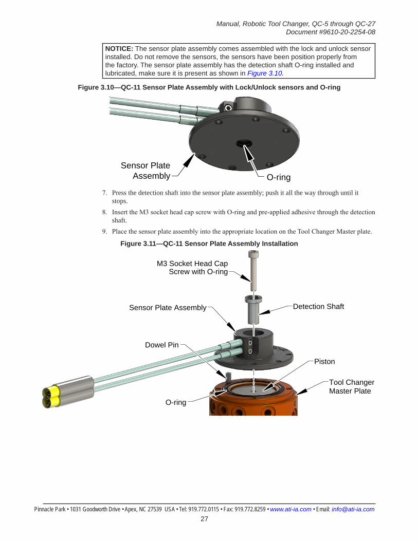
NOTICE: The sensor plate assembly comes assembled with the lock and unlock sensor installed. Do not remove the sensors, the sensors have been position properly from the factory. The sensor plate assembly has the detection shaft O-ring installed and lubricated, make sure it is present as shown in Figure 3.10.
Figure 3.10—QC-11 Sensor Plate Assembly with Lock/Unlock sensors and O-ring
O-ringSensor Plate
Assembly
7. Press the detection shaft into the sensor plate assembly; push it all the way through until it stops.
8. Insert the M3 socket head cap screw with O-ring and pre-applied adhesive through the detection shaft.
9. Place the sensor plate assembly into the appropriate location on the Tool Changer Master plate.
Figure 3.11—QC-11 Sensor Plate Assembly Installation
Sensor Plate Assembly
Tool Changer Master Plate
Dowel Pin
Detection Shaft
M3 Socket Head Cap Screw with O-ring
Piston
O-ring
Manual, Robotic Tool Changer, QC-5 through QC-27Document #9610-20-2254-08
Pinnacle Park • 1031 Goodworth Drive • Apex, NC 27539 USA • Tel: 919.772.0115 • Fax: 919.772.8259 • www.ati-ia.com • Email: [email protected] 28
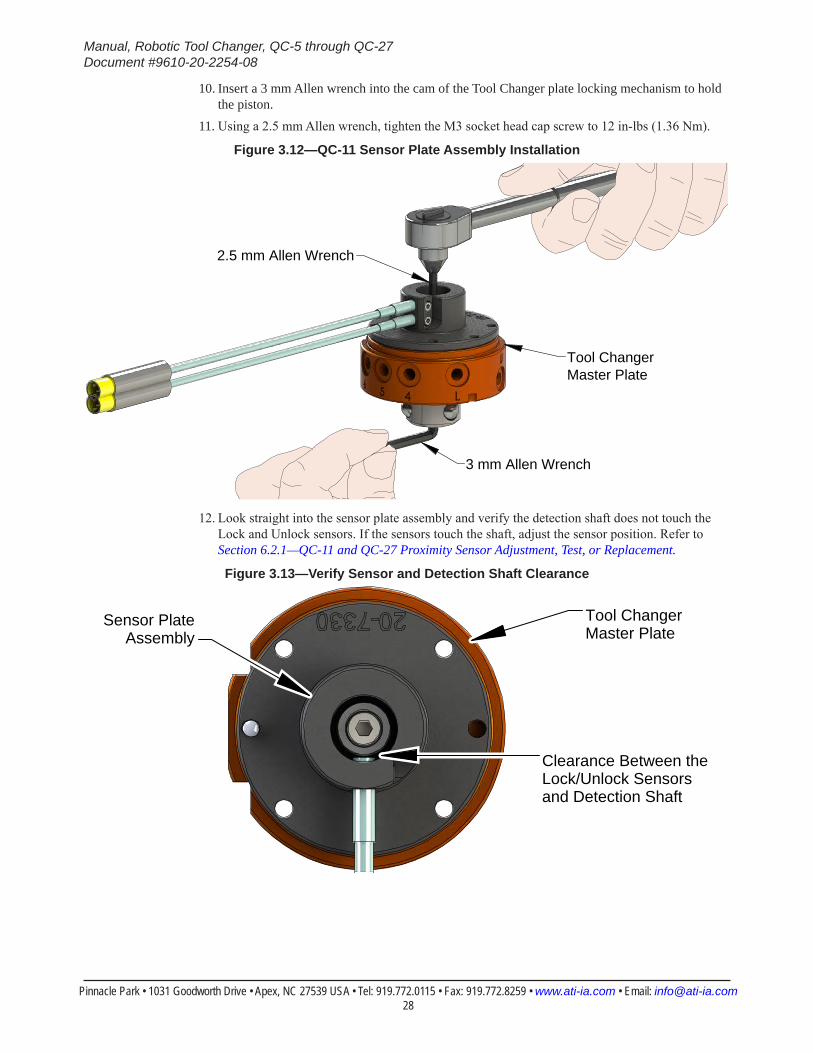
10. Insert a 3 mm Allen wrench into the cam of the Tool Changer plate locking mechanism to hold the piston.
11. Using a 2.5 mm Allen wrench, tighten the M3 socket head cap screw to 12 in-lbs (1.36 Nm).
Figure 3.12—QC-11 Sensor Plate Assembly Installation
Tool Changer Master Plate
3 mm Allen Wrench
2.5 mm Allen Wrench
12. Look straight into the sensor plate assembly and verify the detection shaft does not touch the Lock and Unlock sensors. If the sensors touch the shaft, adjust the sensor position. Refer to Section 6.2.1—QC-11 and QC-27 Proximity Sensor Adjustment, Test, or Replacement.
Figure 3.13—Verify Sensor and Detection Shaft Clearance
Tool Changer Master Plate
Clearance Between the Lock/Unlock Sensors and Detection Shaft
Sensor PlateAssembly

Manual, Robotic Tool Changer, QC-5 through QC-27Document #9610-20-2254-08
Pinnacle Park • 1031 Goodworth Drive • Apex, NC 27539 USA • Tel: 919.772.0115 • Fax: 919.772.8259 • www.ati-ia.com • Email: [email protected] 29
CAUTION: Do not apply Lock or Unlock air pressure to the Tool Changer prior to installing an interface plate. Applying air pressure can damage the cover plate, O-ring or may cause injury to personnel from flying debris. Always install an interface plate and have the Tool Changer mounted securely to the robot before applying air pressure. Refer to Section 3.1—Robot Interface Plates and Section 3.2—Master Plate Installation for more information.
13. Connect the Lock and Unlock sensor cables and manually move the Tool Changer piston to the locked and unlocked positions.
14. Verify the sensors properly work.a. Turn the power on to the sensor.
b. Verify that the Locked signal turns ON and the sensor LED is illuminated when the Tool Changer is in the Locked position.
c. Verify that the Unlocked signal turns ON and the sensor LED is illuminated when the Tool Changer is in the Unlocked position.
d. If not, adjust and test the sensors. Refer to Section 6.2.1—QC-11 and QC-27 Proximity Sensor Adjustment, Test, or Replacement.
15. Install the new interface plate to the robot, and the Tool Changer Master plate to the interface plate, refer to Section 3.2—Master Plate Installation.
16. After the procedure is complete, resume normal operation.
3.8.2 QC-20 and QC-21 SIP Assembly InstallationTools required: 2 mm, 2.5 mm, and 3 mm Allen wrenches (hex key), torque wrenchParts required: 9120-020M-SIP-xxxx or 9120-021M-SIP-xxxx (where xxxx is the custom SIP interface plate)Supplies required: Loctite 222 and Loctite Primer 7649 (if fasteners do not have pre-applied adhesive), magnalube (if necessary)
1. Place the Tool in a secure location.2. Uncouple the Master and Tool plates.3. Turn off and de-energize all energized circuits (e.g. electrical, air, water, etc.).4. Remove the Tool Changer Master plate from the robot and the interface plate; refer to
Section 3.3—Master Plate Removal.
Manual, Robotic Tool Changer, QC-5 through QC-27Document #9610-20-2254-08
Pinnacle Park • 1031 Goodworth Drive • Apex, NC 27539 USA • Tel: 919.772.0115 • Fax: 919.772.8259 • www.ati-ia.com • Email: [email protected] 30
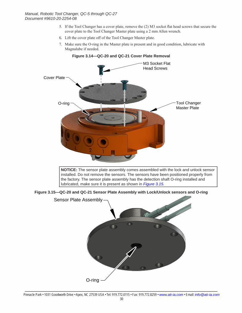
5. If the Tool Changer has a cover plate, remove the (2) M3 socket flat head screws that secure the cover plate to the Tool Changer Master plate using a 2 mm Allen wrench.
6. Lift the cover plate off of the Tool Changer Master plate.7. Make sure the O-ring in the Master plate is present and in good condition, lubricate with
Magnalube if needed.
Figure 3.14—QC-20 and QC-21 Cover Plate Removal
Cover Plate
O-ring Tool Changer Master Plate
M3 Socket Flat Head Screws
NOTICE: The sensor plate assembly comes assembled with the lock and unlock sensor installed. Do not remove the sensors. The sensors have been positioned properly from the factory. The sensor plate assembly has the detection shaft O-ring installed and lubricated, make sure it is present as shown in Figure 3.15.
Figure 3.15—QC-20 and QC-21 Sensor Plate Assembly with Lock/Unlock sensors and O-ring
O-ring
Sensor Plate Assembly
Manual, Robotic Tool Changer, QC-5 through QC-27Document #9610-20-2254-08
Pinnacle Park • 1031 Goodworth Drive • Apex, NC 27539 USA • Tel: 919.772.0115 • Fax: 919.772.8259 • www.ati-ia.com • Email: [email protected] 31
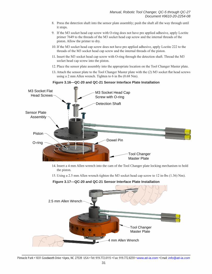
8. Press the detection shaft into the sensor plate assembly; push the shaft all the way through until it stops.
9. If the M3 socket head cap screw with O-ring does not have pre applied adhesive, apply Loctite primer 7649 to the threads of the M3 socket head cap screw and the internal threads of the piston. Allow the primer to dry.
10. If the M3 socket head cap screw does not have pre applied adhesive, apply Loctite 222 to the threads of the M3 socket head cap screw and the internal threads of the piston.
11. Insert the M3 socket head cap screw with O-ring through the detection shaft. Thread the M3 socket head cap screw into the piston.
12. Place the sensor plate assembly into the appropriate location on the Tool Changer Master plate. 13. Attach the sensor plate to the Tool Changer Master plate with the (2) M3 socket flat head screws
using a 2 mm Allen wrench. Tighten to 6 in lbs (0.68 Nm).
Figure 3.16—QC-20 and QC-21 Sensor Interface Plate Installation
Sensor Plate Assembly
Tool Changer Master Plate
Dowel Pin
Detection Shaft
M3 Socket Head Cap Screw with O-ring
Piston
O-ring
M3 Socket FlatHead Screws
14. Insert a 4 mm Allen wrench into the cam of the Tool Changer plate locking mechanism to hold the piston.
15. Using a 2.5 mm Allen wrench tighten the M3 socket head cap screw to 12 in-lbs (1.36) Nm).
Figure 3.17—QC-20 and QC-21 Sensor Interface Plate Installation
Tool Changer Master Plate
4 mm Allen Wrench
2.5 mm Allen Wrench
Manual, Robotic Tool Changer, QC-5 through QC-27Document #9610-20-2254-08
Pinnacle Park • 1031 Goodworth Drive • Apex, NC 27539 USA • Tel: 919.772.0115 • Fax: 919.772.8259 • www.ati-ia.com • Email: [email protected] 32
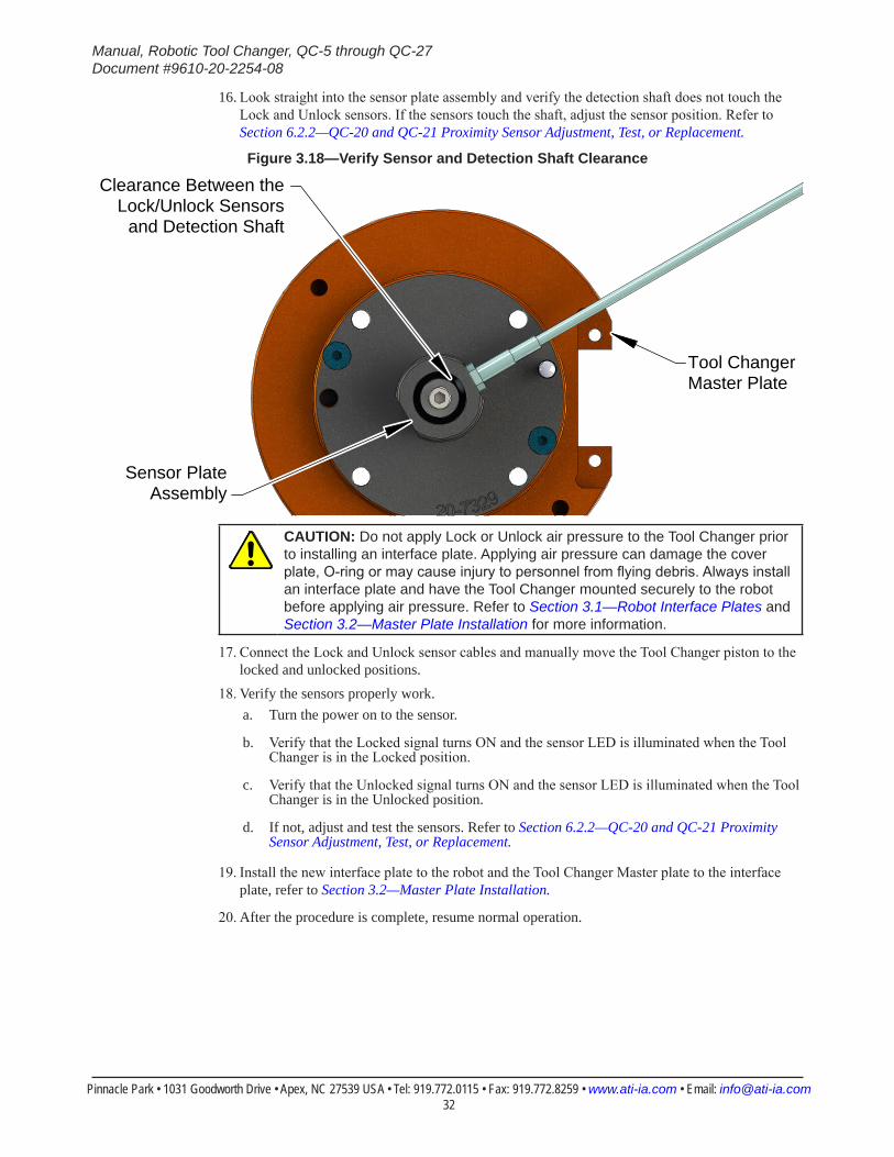
16. Look straight into the sensor plate assembly and verify the detection shaft does not touch the Lock and Unlock sensors. If the sensors touch the shaft, adjust the sensor position. Refer to Section 6.2.2—QC-20 and QC-21 Proximity Sensor Adjustment, Test, or Replacement.
Figure 3.18—Verify Sensor and Detection Shaft Clearance
Tool Changer Master Plate
Clearance Between theLock/Unlock Sensors
and Detection Shaft
Sensor PlateAssembly
CAUTION: Do not apply Lock or Unlock air pressure to the Tool Changer prior to installing an interface plate. Applying air pressure can damage the cover plate, O-ring or may cause injury to personnel from flying debris. Always install an interface plate and have the Tool Changer mounted securely to the robot before applying air pressure. Refer to Section 3.1—Robot Interface Plates and Section 3.2—Master Plate Installation for more information.
17. Connect the Lock and Unlock sensor cables and manually move the Tool Changer piston to the locked and unlocked positions.
18. Verify the sensors properly work.a. Turn the power on to the sensor.
b. Verify that the Locked signal turns ON and the sensor LED is illuminated when the Tool Changer is in the Locked position.
c. Verify that the Unlocked signal turns ON and the sensor LED is illuminated when the Tool Changer is in the Unlocked position.
d. If not, adjust and test the sensors. Refer to Section 6.2.2—QC-20 and QC-21 Proximity Sensor Adjustment, Test, or Replacement.
19. Install the new interface plate to the robot and the Tool Changer Master plate to the interface plate, refer to Section 3.2—Master Plate Installation.
20. After the procedure is complete, resume normal operation.
Manual, Robotic Tool Changer, QC-5 through QC-27Document #9610-20-2254-08
Pinnacle Park • 1031 Goodworth Drive • Apex, NC 27539 USA • Tel: 919.772.0115 • Fax: 919.772.8259 • www.ati-ia.com • Email: [email protected] 33
3.9 Lock and Unlock Pneumatic and Valve RequirementsTo lock or unlock the Tool Changer, a constant supply of compressed air is required. If there is a loss of air pressure in the locked state, the cam profile prevents the master plate and tool plate from unlocking, and the Tool Changer goes into the fail-safe condition.
CAUTION: Do not use or transport the Tool Changer in the fail-safe condition, a state where the master plate is locked to a tool plate with no air pressure supplied. Damage to the locking mechanism might occur. Restore proper air pressure before continuing to use the Tool Changer.
3.9.1 Air RequirementsProper operation of the locking mechanism requires a constant supply of clean, dry, non-lubricated air, with the following conditions: • Pressure range: 60-100 psi (4.1–6.9 Bar).• Filter minimum: 40 microns. • Flow maximum: 1/3 CFM at 70 psi (4.8 Bar), when cycled continuously.
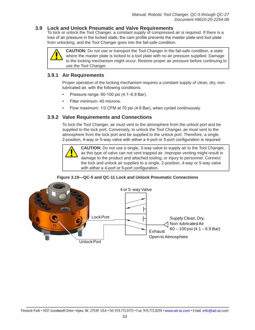
3.9.2 Valve Requirements and ConnectionsTo lock the Tool Changer, air must vent to the atmosphere from the unlock port and be supplied to the lock port. Conversely, to unlock the Tool Changer, air must vent to the atmosphere from the lock port and be supplied to the unlock port. Therefore, a single, 2-position, 4-way or 5-way valve with either a 4-port or 5-port configuration is required.
CAUTION: Do not use a single, 3-way valve to supply air to the Tool Changer, as this type of valve can not vent trapped air. Improper venting might result in damage to the product and attached tooling, or injury to personnel. Connect the lock and unlock air supplies to a single, 2-position, 4-way or 5-way valve with either a 4-port or 5-port configuration.
Figure 3.19—QC-5 and QC-11 Lock and Unlock Pneumatic Connections
4 or 5 -way Valve
Supply Clean, Dry, Non-lubricated Air 60 – 100 psi (4.1 – 6.9 Bar)Exhaust
Open to Atmosphere
Lock Port
Unlock Port
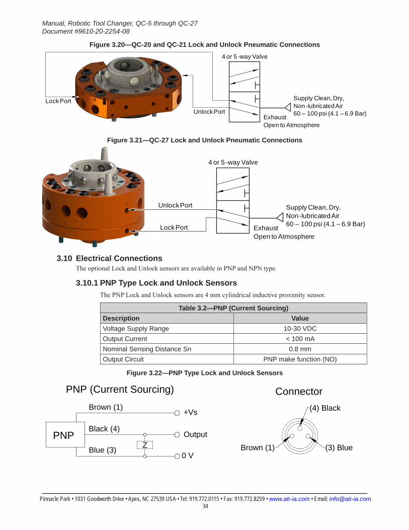
Manual, Robotic Tool Changer, QC-5 through QC-27Document #9610-20-2254-08
Pinnacle Park • 1031 Goodworth Drive • Apex, NC 27539 USA • Tel: 919.772.0115 • Fax: 919.772.8259 • www.ati-ia.com • Email: [email protected] 34
Figure 3.20—QC-20 and QC-21 Lock and Unlock Pneumatic Connections
4 or 5 -way Valve
Supply Clean, Dry, Non-lubricated Air 60 – 100 psi (4.1 – 6.9 Bar)Exhaust
Open to Atmosphere
Lock Port
Unlock Port
Figure 3.21—QC-27 Lock and Unlock Pneumatic Connections
4 or 5 -way Valve
Supply Clean, Dry, Non-lubricated Air 60 – 100 psi (4.1 – 6.9 Bar)Exhaust
Open to AtmosphereLock Port
Unlock Port
3.10 Electrical ConnectionsThe optional Lock and Unlock sensors are available in PNP and NPN type.
3.10.1 PNP Type Lock and Unlock SensorsThe PNP Lock and Unlock sensors are 4 mm cylindrical inductive proximity sensor.
Table 3.2—PNP (Current Sourcing)Description ValueVoltage Supply Range 10-30 VDCOutput Current < 100 mANominal Sensing Distance Sn 0.8 mmOutput Circuit PNP make function (NO)
Figure 3.22—PNP Type Lock and Unlock Sensors
(3) BlueBrown (1)
(4) BlackBrown (1)
Black (4)
Blue (3)
+Vs
Output
0 V
PNPZ
ConnectorPNP (Current Sourcing)
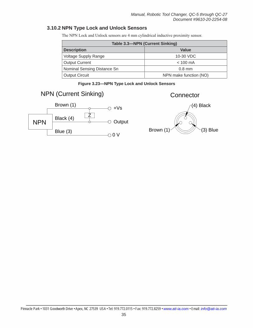
Manual, Robotic Tool Changer, QC-5 through QC-27Document #9610-20-2254-08
Pinnacle Park • 1031 Goodworth Drive • Apex, NC 27539 USA • Tel: 919.772.0115 • Fax: 919.772.8259 • www.ati-ia.com • Email: [email protected] 35
3.10.2 NPN Type Lock and Unlock SensorsThe NPN Lock and Unlock sensors are 4 mm cylindrical inductive proximity sensor.
Table 3.3—NPN (Current Sinking)Description ValueVoltage Supply Range 10-30 VDCOutput Current < 100 mANominal Sensing Distance Sn 0.8 mmOutput Circuit NPN make function (NO)
Figure 3.23—NPN Type Lock and Unlock Sensors
(3) BlueBrown (1)
(4) BlackBrown (1)
Black (4)
Blue (3)
+Vs
Output
0 V
NPNZ
ConnectorNPN (Current Sinking)
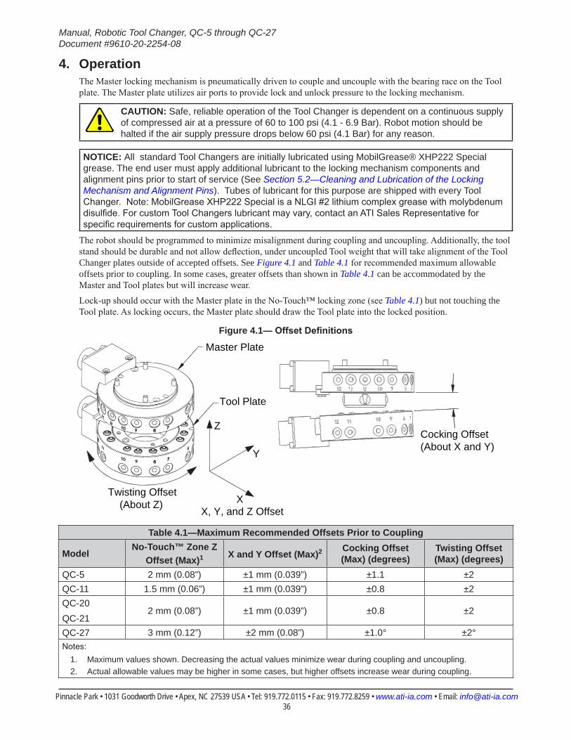
Manual, Robotic Tool Changer, QC-5 through QC-27Document #9610-20-2254-08
Pinnacle Park • 1031 Goodworth Drive • Apex, NC 27539 USA • Tel: 919.772.0115 • Fax: 919.772.8259 • www.ati-ia.com • Email: [email protected] 36
4. OperationThe Master locking mechanism is pneumatically driven to couple and uncouple with the bearing race on the Tool plate. The Master plate utilizes air ports to provide lock and unlock pressure to the locking mechanism.
CAUTION: Safe, reliable operation of the Tool Changer is dependent on a continuous supply of compressed air at a pressure of 60 to 100 psi (4.1 - 6.9 Bar). Robot motion should be halted if the air supply pressure drops below 60 psi (4.1 Bar) for any reason.
NOTICE: All standard Tool Changers are initially lubricated using MobilGrease® XHP222 Special grease. The end user must apply additional lubricant to the locking mechanism components and alignment pins prior to start of service (See Section 5.2—Cleaning and Lubrication of the Locking Mechanism and Alignment Pins). Tubes of lubricant for this purpose are shipped with every Tool Changer. Note: MobilGrease XHP222 Special is a NLGI #2 lithium complex grease with molybdenum disulfide. For custom Tool Changers lubricant may vary, contact an ATI Sales Representative for specific requirements for custom applications.
The robot should be programmed to minimize misalignment during coupling and uncoupling. Additionally, the tool stand should be durable and not allow deflection, under uncoupled Tool weight that will take alignment of the Tool Changer plates outside of accepted offsets. See Figure 4.1 and Table 4.1 for recommended maximum allowable offsets prior to coupling. In some cases, greater offsets than shown in Table 4.1 can be accommodated by the Master and Tool plates but will increase wear.
Lock-up should occur with the Master plate in the No-Touch™ locking zone (see Table 4.1) but not touching the Tool plate. As locking occurs, the Master plate should draw the Tool plate into the locked position.
Figure 4.1—OffsetDefinitions
Master Plate
Tool Plate
Cocking Offset(About X and Y)
Twisting Offset (About Z)
Z
Y
XX, Y, and Z Offset
Table 4.1—Maximum Recommended Offsets Prior to Coupling
ModelNo-Touch™ Zone Z
Offset (Max)1 X and Y Offset (Max)2 Cocking Offset (Max) (degrees)
Twisting Offset (Max) (degrees)
QC-5 2 mm (0.08”) ±1 mm (0.039”) ±1.1 ±2QC-11 1.5 mm (0.06”) ±1 mm (0.039”) ±0.8 ±2QC-20QC-21
2 mm (0.08”) ±1 mm (0.039”) ±0.8 ±2
QC-27 3 mm (0.12”) ±2 mm (0.08”) ±1.0° ±2°Notes:
1. Maximum values shown. Decreasing the actual values minimize wear during coupling and uncoupling.2. Actual allowable values may be higher in some cases, but higher offsets increase wear during coupling.
Manual, Robotic Tool Changer, QC-5 through QC-27Document #9610-20-2254-08
Pinnacle Park • 1031 Goodworth Drive • Apex, NC 27539 USA • Tel: 919.772.0115 • Fax: 919.772.8259 • www.ati-ia.com • Email: [email protected] 37
4.1 Coupling SequenceCAUTION: The locking mechanism must be in the unlock position when attempting to couple the Tool Changer. Failure to adhere to this condition may result in damage to the unit and/or the robot.
1. Position the Master plate above the Tool plate with the air supplied to the Unlock Port (if equipped, the Unlock sensor will indicate the Tool Changer is Unlocked).
2. Move the Master plate toward the Tool plate so that the (2) alignment pins enter the alignment holes on the opposite plate. Program the robot so that the Master plate and Tool plate are aligned axially and are parallel to each other as closely as possible. This will minimize Tool movement and subsequent wear during lock-up.
CAUTION: No-Touch™ locking technology allows the unit to couple with a separation distance between the Master and Tool. Direct contact of the Master and Tool mating surfaces is not suggested or required prior to coupling. Contact may result in damage to the unit and/or the robot.
3. When the (2) faces are within the specified No-Touch™ distance, release the pressure from the Unlock port and supply air to the Lock port. The Tool plate is drawn toward the Master plate and coupled. Air must be maintained on the Lock Port during operation to assure rigid coupling (if equipped, the Lock sensor will indicate the Tool Changer is in the Locked position).
4. A sufficient delay must be programmed between locking valve actuation and robot motion so that the locking process is complete before moving the robot.
CAUTION: If air pressure is lost during operation, ATI’s patented fail-safe design prevents the Tool plate from being released. Do not use the Tool Changer in a fail-safe condition. Re-establish air pressure and ensure the Tool Changer is in a secure lock position before returning to normal operations.
4.2 Fail-Safe OperationA fail-safe condition occurs when there is an unintended loss of lock air pressure to the Master plate. When air pressure is lost, the Tool Changer relaxes and there may be a slight separation between the Master and Tool plates. The lock sensor may indicate that the unit is not locked. ATI’s patented fail-safe feature utilizes a multi-tapered cam to trap the ball bearings and prevent an unintended release of the Tool plate. Positional accuracy of the tooling is not maintained during this fail-safe condition. Do not operate the Tool Changer in the fail-safe condition. If source air is lost to the unit, movement should be halted until air pressure is restored. After air pressure is re-established to the Master plate, the locking mechanism will energize and securely lock the Master and Tool plates together. In some cases when the load on the tool changer is significantly off center, it may be necessary to position the load underneath the tool changer or return the tool to the tool storage location to ensure a secure lock condition. If equipped, make sure the lock sensor indicates the Tool Changer is in the locked position before resuming normal operations. Consult your Control/Signal Module Manual for specific error recovery information.
CAUTION: Do not use the Tool Changer in a fail-safe condition. Damage to the locking mechanism could occur. Re-establish air pressure and ensure the Tool Changer is in a secure lock position before returning to normal operations.
Manual, Robotic Tool Changer, QC-5 through QC-27Document #9610-20-2254-08
Pinnacle Park • 1031 Goodworth Drive • Apex, NC 27539 USA • Tel: 919.772.0115 • Fax: 919.772.8259 • www.ati-ia.com • Email: [email protected] 38
4.3 Uncoupling Sequence1. Position the Tool plate in the tool stand such that there is little or no contact force between the Tool plate
and tool stand. 2. Release air on the Lock port and apply air to the Unlock Port (if equipped, the Unlock sensor will
indicate the Tool Changer is in the Unlocked position).
NOTICE: The air will cause the locking mechanism to be released and the weight of the Tool plate and attached tooling will assist in its removal. The Tool weight assists in uncoupling if the Tool is released in the vertical position only.
3. A sufficient delay must be programmed between unlocking valve actuation and robot motion so that the unlocking process is complete and the Tool plate is fully released before moving the robot.
4. Move the Master plate axially away from the Tool plate.5. In automated Tool change applications, it is recommended that a Tool presence sensor(s) be used in the
tool stand to verify that the Tool is present and that the Tool remains in place as the robot moves away after the unlocking process.
4.4 ToolIdentificationWhen using multiple Tools, it is good practice to implement a Tool-ID system that identifies each Tool with a unique code. Tool-ID can be used to verify that the robot has picked up the proper Tool. Modules with Tool-ID are available from ATI, refer to our Web site http://www.ati-ia.com/products/toolchanger/tool_changer_modules.aspx for products available or contact ATI for assistance.

Manual, Robotic Tool Changer, QC-5 through QC-27Document #9610-20-2254-08
Pinnacle Park • 1031 Goodworth Drive • Apex, NC 27539 USA • Tel: 919.772.0115 • Fax: 919.772.8259 • www.ati-ia.com • Email: [email protected] 39
4.5 Tool Storage ConsiderationsNOTICE: Tool stand design is critical to operation of the Tool Changer. Improperly designed tool stands can cause jamming and excessive wear of the Tool Changer components.
Tool plates with customer tooling attached may be stored in a tool stand. ATI provides compatible tool stands designed for durability, longevity, and maximum adaptability to fit most customers’ applications. The ATI TSS (Tool Stand Small) system is compatible with ATI Tool Changer sizes QC-001 to QC-41. The TSS systems can be equipped with horizontal modules, clamp modules, and different types of tool sensing. Two mounting styles are available: a pin and bushing style and a pin and rack style. Visit the ATI Web Site http://www.ati-ia.com/products/toolchanger/toolstand/small/SmallStand.aspx for products available or contact ATI for assistance.If the customer is supplying the tool stand, it must provide a fixed, repeatable, level, and stable position for tool pick-up and drop-off. The tool stand must support the weight of the Tool Changer Tool plate, tool interface plate, optional modules, cables, hoses, and customer tooling without allowing deflection in excess of the offsets.Ideally, the tool should be hanging vertically in the tool stand so that gravity assists to uncouple the Tool plate from the Master plate during unlocking. It is possible to design tool stands that hold tools in the horizontal position, but the necessary compliance must be provided during coupling and uncoupling. In general, “horizontal-position” tool stands cause more wear on the locking mechanism and locating features of the Tool and tool stand. A variety of methods may be used to position the Tool in the tool stand. A common method is to use tapered alignment pins and bushings. Robot programming and positional repeatability are vital in tool pick-up and drop-off.A sensor that detects the presence of a Tool in the tool stand is recommended. The sensor may be used prior to coupling to ensure there is a Tool properly seated in the stand. Sensors may also be used as the robot starts to move away after uncoupling. Sensors provide a safety measure if the tool becomes jammed in the stand or if the Tool fails to release from the robot. Proximity sensors should be positioned so that the sensing face is vertical to prevent metal shavings, weld spatter, or other debris from falling on the sensor and creating false readings.Tool stands debris shields can cover Tools and modules to protect them in dirty environments, such as grinding or welding. Alternatively, positioning tool stands in areas shielded from weld spatter, fluids, adhesives, or other debris would eliminate the need for debris shields.

Manual, Robotic Tool Changer, QC-5 through QC-27Document #9610-20-2254-08
Pinnacle Park • 1031 Goodworth Drive • Apex, NC 27539 USA • Tel: 919.772.0115 • Fax: 919.772.8259 • www.ati-ia.com • Email: [email protected] 40
5. MaintenanceWARNING: Do not perform maintenance or repair on Tool Changer or modules unless the Tool is safely supported or placed in the tool stand, all energized circuits (e.g. electrical, air, water, etc.) are turned off, pressurized connections purged and power discharged from circuits in accordance with the customer’s safety practices and policies. Injury or equipment damage can occur with Tool not placed and energized circuits on. Place the Tool safely in the tool stand, turn off and discharge all energized circuits, purge all pressurized connections, verify all energized circuits are de-energized before performing maintenance or repair on Tool Changer or modules.
NOTICE: The cleanliness of the work environment strongly influences the trouble free operation of the Tool Changer. The dirtier the environment, the greater the need for protection against debris. Protection of the entire EOAT, the Master, the Tool and all of the modules may be necessary. Protective measures include the following: 1) Placement of tool stands away from debris generators.2) Covers incorporated into the tool stands.3) Guards, deflectors, air curtains, and similar devices built into the EOAT and the tool stand.
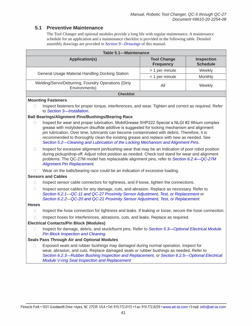
Manual, Robotic Tool Changer, QC-5 through QC-27Document #9610-20-2254-08
Pinnacle Park • 1031 Goodworth Drive • Apex, NC 27539 USA • Tel: 919.772.0115 • Fax: 919.772.8259 • www.ati-ia.com • Email: [email protected] 41
5.1 Preventive MaintenanceThe Tool Changer and optional modules provide a long life with regular maintenance. A maintenance schedule for an application and a maintenance checklist is provided in the following table. Detailed assembly drawings are provided in Section 9—Drawings of this manual.
Table 5.1—MaintenanceApplication(s) Tool Change
FrequencyInspection Schedule
General Usage Material Handling Docking Station> 1 per minute Weekly< 1 per minute Monthly
Welding/Servo/Deburring, Foundry Operations (Dirty Environments) All Weekly
ChecklistMounting Fasteners
г Inspect fasteners for proper torque, interferences, and wear. Tighten and correct as required. Refer to Section 3—Installation.
Ball Bearings/Alignment Pins/Bushings/Bearing Race г Inspect for wear and proper lubrication. MobilGrease XHP222 Special a NLGI #2 lithium complex
grease with molybdenum disulfide additive is suggested for locking mechanism and alignment pin lubrication. Over time, lubricants can become contaminated with debris. Therefore, it is recommended to thoroughly clean the existing grease and replace with new as needed. See Section 5.2—Cleaning and Lubrication of the Locking Mechanism and Alignment Pins.
г Inspect for excessive alignment pin/bushing wear that may be an indication of poor robot position during pickup/drop-off. Adjust robot position as needed. Check tool stand for wear and alignment problems. The QC-27M model has replaceable alignment pins, refer to Section 6.2.4—QC-27M Alignment Pin Replacement.
г Wear on the balls/bearing race could be an indication of excessive loading.Sensors and Cables
г Inspect sensor cable connectors for tightness, and if loose, tighten the connections. г Inspect sensor cables for any damage, cuts, and abrasion. Replace as necessary. Refer to
Section 6.2.1—QC-11 and QC-27 Proximity Sensor Adjustment, Test, or Replacement or Section 6.2.2—QC-20 and QC-21 Proximity Sensor Adjustment, Test, or Replacement
Hoses г Inspect the hose connection for tightness and leaks. If leaking or loose, secure the hose connection. г Inspect hoses for interferences, abrasions, cuts, and leaks. Replace as required.
Electrical Contacts/Pin Block (Modules) г Inspect for damage, debris, and stuck/burnt pins. Refer to Section 5.3—Optional Electrical Module
Pin Block Inspection and Cleaning.Seals Pass Through Air and Optional Modules
г Exposed seals and rubber bushings may damaged during normal operation. Inspect for wear, abrasion, and cuts. Replace damaged seals or rubber bushings as needed. Refer to Section 6.2.3—Rubber Bushing Inspection and Replacement, or Section 6.2.5—Optional Electrical Module V-ring Seal Inspection and Replacement

Manual, Robotic Tool Changer, QC-5 through QC-27Document #9610-20-2254-08
Pinnacle Park • 1031 Goodworth Drive • Apex, NC 27539 USA • Tel: 919.772.0115 • Fax: 919.772.8259 • www.ati-ia.com • Email: [email protected] 42
5.2 Cleaning and Lubrication of the Locking Mechanism and Alignment Pins1. Place the Tool in a secure location.2. Uncouple the Master and Tool plates.3. Turn off and de-energize all energized circuits (e.g. electrical, air, water, etc.).4. Use a clean rag to thoroughly remove any lubricant and debris from the ball bearings, male coupling,
cam, and alignment pins.
Figure 5.1—Cleaning Ball Bearings and Outer Surfaces of Male Coupling
5. Use a clean rag to thoroughly remove any lubricant and debris from the inner surface of the male coupling and cam.
Figure 5.2—Cleaning Ball Bearings, Cam and Inner Surfaces of Male Coupling
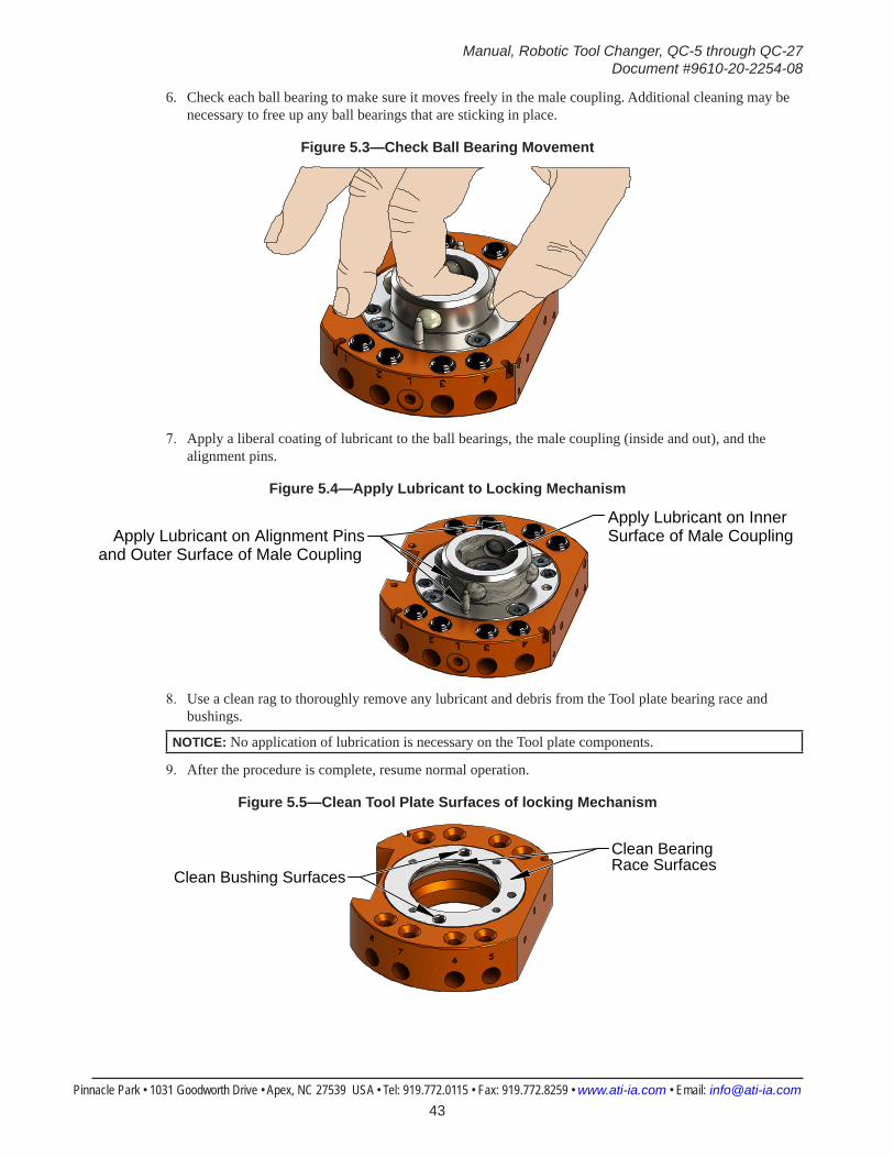
Manual, Robotic Tool Changer, QC-5 through QC-27Document #9610-20-2254-08
Pinnacle Park • 1031 Goodworth Drive • Apex, NC 27539 USA • Tel: 919.772.0115 • Fax: 919.772.8259 • www.ati-ia.com • Email: [email protected] 43
6. Check each ball bearing to make sure it moves freely in the male coupling. Additional cleaning may be necessary to free up any ball bearings that are sticking in place.
Figure 5.3—Check Ball Bearing Movement
7. Apply a liberal coating of lubricant to the ball bearings, the male coupling (inside and out), and the alignment pins.
Figure 5.4—Apply Lubricant to Locking Mechanism
Apply Lubricant on Inner Surface of Male CouplingApply Lubricant on Alignment Pins
and Outer Surface of Male Coupling
8. Use a clean rag to thoroughly remove any lubricant and debris from the Tool plate bearing race and bushings.
NOTICE: No application of lubrication is necessary on the Tool plate components.
9. After the procedure is complete, resume normal operation.
Figure 5.5—Clean Tool Plate Surfaces of locking Mechanism
Clean Bearing Race Surfaces
Clean Bushing Surfaces
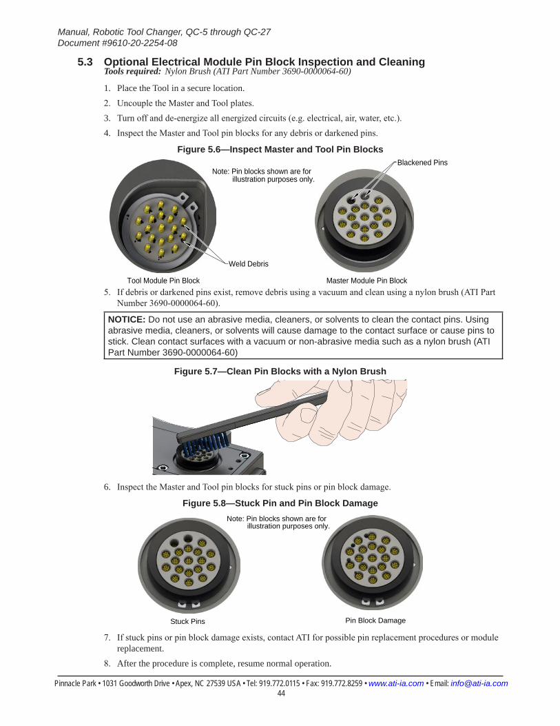
Manual, Robotic Tool Changer, QC-5 through QC-27Document #9610-20-2254-08
Pinnacle Park • 1031 Goodworth Drive • Apex, NC 27539 USA • Tel: 919.772.0115 • Fax: 919.772.8259 • www.ati-ia.com • Email: [email protected] 44
5.3 Optional Electrical Module Pin Block Inspection and CleaningTools required: Nylon Brush (ATI Part Number 3690-0000064-60)
1. Place the Tool in a secure location.2. Uncouple the Master and Tool plates.3. Turn off and de-energize all energized circuits (e.g. electrical, air, water, etc.).4. Inspect the Master and Tool pin blocks for any debris or darkened pins.
Figure 5.6—Inspect Master and Tool Pin Blocks
Tool Module Pin Block Master Module Pin Block
Note: Pin blocks shown are for illustration purposes only.
Weld Debris
Blackened Pins
5. If debris or darkened pins exist, remove debris using a vacuum and clean using a nylon brush (ATI Part Number 3690-0000064-60).
NOTICE: Do not use an abrasive media, cleaners, or solvents to clean the contact pins. Using abrasive media, cleaners, or solvents will cause damage to the contact surface or cause pins to stick. Clean contact surfaces with a vacuum or non-abrasive media such as a nylon brush (ATI Part Number 3690-0000064-60)
Figure 5.7—Clean Pin Blocks with a Nylon Brush
6. Inspect the Master and Tool pin blocks for stuck pins or pin block damage.
Figure 5.8—Stuck Pin and Pin Block Damage
Stuck Pins Pin Block Damage
Note: Pin blocks shown are for illustration purposes only.
7. If stuck pins or pin block damage exists, contact ATI for possible pin replacement procedures or module replacement.
8. After the procedure is complete, resume normal operation.
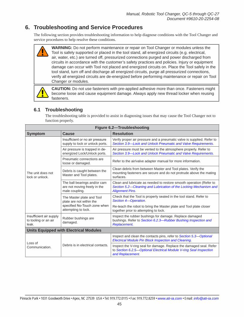
Manual, Robotic Tool Changer, QC-5 through QC-27Document #9610-20-2254-08
Pinnacle Park • 1031 Goodworth Drive • Apex, NC 27539 USA • Tel: 919.772.0115 • Fax: 919.772.8259 • www.ati-ia.com • Email: [email protected] 45
6. Troubleshooting and Service ProceduresThe following section provides troubleshooting information to help diagnose conditions with the Tool Changer and service procedures to help resolve these conditions.
WARNING: Do not perform maintenance or repair on Tool Changer or modules unless the Tool is safely supported or placed in the tool stand, all energized circuits (e.g. electrical, air, water, etc.) are turned off, pressurized connections purged and power discharged from circuits in accordance with the customer’s safety practices and policies. Injury or equipment damage can occur with Tool not placed and energized circuits on. Place the Tool safely in the tool stand, turn off and discharge all energized circuits, purge all pressurized connections, verify all energized circuits are de-energized before performing maintenance or repair on Tool Changer or modules.
CAUTION: Do not use fasteners with pre-applied adhesive more than once. Fasteners might become loose and cause equipment damage. Always apply new thread locker when reusing fasteners.
6.1 TroubleshootingThe troubleshooting table is provided to assist in diagnosing issues that may cause the Tool Changer not to function properly.
Figure 6.2—TroubleshootingSymptom Cause Resolution
The unit does not lock or unlock.
Insufficient or no air pressure supply to lock or unlock ports.
Verify proper air pressure and a pneumatic valve is supplied. Refer to Section 3.9—Lock and Unlock Pneumatic and Valve Requirements.
Air pressure is trapped in de-energized Lock/Unlock ports.
Air pressure must be vented to the atmosphere properly. Refer to Section 3.9—Lock and Unlock Pneumatic and Valve Requirements.
Pneumatic connections are loose or damaged. Refer to the air/valve adapter manual for more information.
Debris is caught between the Master and Tool plates.
Clean debris from between Master and Tool plates. Verify the mounting fasteners are secure and do not protrude above the mating surfaces.
The ball bearings and/or cam are not moving freely in the male coupling.
Clean and lubricate as needed to restore smooth operation (Refer to Section 5.2—Cleaning and Lubrication of the Locking Mechanism and Alignment Pins.
The Master plate and Tool plate are not within the specified No-Touch zone when attempting to lock.
Check that the Tool is properly seated in the tool stand. Refer to Section 4—Operation.
Re-teach the robot to bring the Master plate and Tool plate closer together prior to attempting to lock.
Insufficient air supply to tooling or an air leak.
Rubber bushings are damaged.
Inspect the rubber bushings for damage. Replace damaged bushings. Refer to Section 6.2.3—Rubber Bushing Inspection and Replacement.
Units Equipped with Electrical Modules
Loss of Communication. Debris is in electrical contacts.
Inspect and clean the contacts pins, refer to Section 5.3—Optional Electrical Module Pin Block Inspection and Cleaning.
Inspect the V-ring seal for damage. Replace the damaged seal. Refer to Section 6.2.5—Optional Electrical Module V-ring Seal Inspection and Replacement.
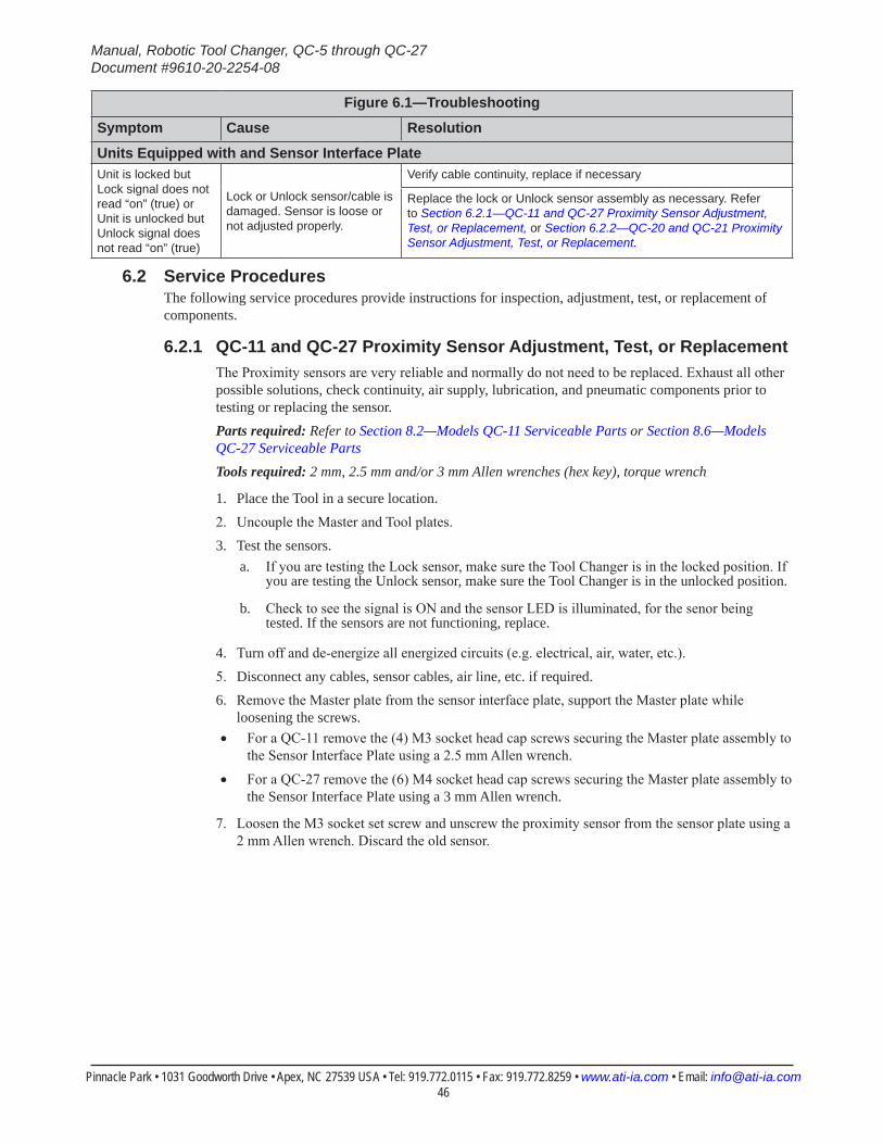
Manual, Robotic Tool Changer, QC-5 through QC-27Document #9610-20-2254-08
Pinnacle Park • 1031 Goodworth Drive • Apex, NC 27539 USA • Tel: 919.772.0115 • Fax: 919.772.8259 • www.ati-ia.com • Email: [email protected] 46
Figure 6.1—Troubleshooting
Symptom Cause Resolution
Units Equipped with and Sensor Interface PlateUnit is locked but Lock signal does not read “on” (true) or Unit is unlocked but Unlock signal does not read “on” (true)
Lock or Unlock sensor/cable is damaged. Sensor is loose or not adjusted properly.
Verify cable continuity, replace if necessary
Replace the lock or Unlock sensor assembly as necessary. Refer to Section 6.2.1—QC-11 and QC-27 Proximity Sensor Adjustment, Test, or Replacement, or Section 6.2.2—QC-20 and QC-21 Proximity Sensor Adjustment, Test, or Replacement.
6.2 Service ProceduresThe following service procedures provide instructions for inspection, adjustment, test, or replacement of components.
6.2.1 QC-11 and QC-27 Proximity Sensor Adjustment, Test, or ReplacementThe Proximity sensors are very reliable and normally do not need to be replaced. Exhaust all other possible solutions, check continuity, air supply, lubrication, and pneumatic components prior to testing or replacing the sensor.Parts required: Refer to Section 8.2—Models QC-11 Serviceable Parts or Section 8.6—Models QC-27 Serviceable PartsTools required: 2 mm, 2.5 mm and/or 3 mm Allen wrenches (hex key), torque wrench
1. Place the Tool in a secure location.2. Uncouple the Master and Tool plates.3. Test the sensors.
a. If you are testing the Lock sensor, make sure the Tool Changer is in the locked position. If you are testing the Unlock sensor, make sure the Tool Changer is in the unlocked position.
b. Check to see the signal is ON and the sensor LED is illuminated, for the senor being tested. If the sensors are not functioning, replace.
4. Turn off and de-energize all energized circuits (e.g. electrical, air, water, etc.).5. Disconnect any cables, sensor cables, air line, etc. if required.6. Remove the Master plate from the sensor interface plate, support the Master plate while
loosening the screws. • For a QC-11 remove the (4) M3 socket head cap screws securing the Master plate assembly to
the Sensor Interface Plate using a 2.5 mm Allen wrench.
• For a QC-27 remove the (6) M4 socket head cap screws securing the Master plate assembly to the Sensor Interface Plate using a 3 mm Allen wrench.
7. Loosen the M3 socket set screw and unscrew the proximity sensor from the sensor plate using a 2 mm Allen wrench. Discard the old sensor.
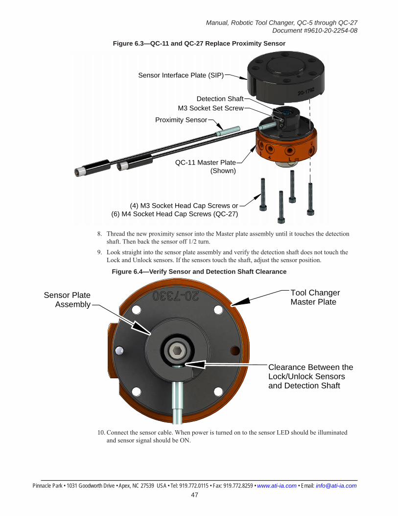
Manual, Robotic Tool Changer, QC-5 through QC-27Document #9610-20-2254-08
Pinnacle Park • 1031 Goodworth Drive • Apex, NC 27539 USA • Tel: 919.772.0115 • Fax: 919.772.8259 • www.ati-ia.com • Email: [email protected] 47
Figure 6.3—QC-11 and QC-27 Replace Proximity Sensor
Proximity Sensor
Sensor Interface Plate (SIP)
M3 Socket Set Screw
(4) M3 Socket Head Cap Screws or(6) M4 Socket Head Cap Screws (QC-27)
QC-11 Master Plate(Shown)
Detection Shaft
8. Thread the new proximity sensor into the Master plate assembly until it touches the detection shaft. Then back the sensor off 1/2 turn.
9. Look straight into the sensor plate assembly and verify the detection shaft does not touch the Lock and Unlock sensors. If the sensors touch the shaft, adjust the sensor position.
Figure 6.4—Verify Sensor and Detection Shaft Clearance
Tool Changer Master Plate
Clearance Between the Lock/Unlock Sensors and Detection Shaft
Sensor PlateAssembly
10. Connect the sensor cable. When power is turned on to the sensor LED should be illuminated and sensor signal should be ON.

Manual, Robotic Tool Changer, QC-5 through QC-27Document #9610-20-2254-08
Pinnacle Park • 1031 Goodworth Drive • Apex, NC 27539 USA • Tel: 919.772.0115 • Fax: 919.772.8259 • www.ati-ia.com • Email: [email protected] 48
CAUTION: Do not operate locking mechanism with sensor touching the detection shaft. Operating the locking mechanism with the sensor touching the detection shaft will damage the sensor. Back off the sensor ½ turn and secure with the set screw before operating the locking mechanism.
11. Turn the M3 socket set screw, until it contacts the sensor, and tighten 1/4 turn using a 2 mm Allen wrench.
CAUTION: Be careful not to over tighten set screw. Over tightening set screw can cause damage to the proximity sensor. Tighten until the nylon tip engages with the sensor threads and tighten 1/4 turn more.
12. Attach the Master plate to the interface plate:• For a QC-11 secure the Master plate to the interface plate using the (4) M3 socket head cap
screws using a 2.5 mm Allen wrench. Tighten to 10 in-lbs (1.13 Nm).
• For a QC-27 secure the Master plate to the interface plate using the (6) M4 socket head cap screws using a 3 mm Allen wrench. Tighten to 15 in-lbs (1.68 Nm).
13. Connect other utilities to the optional modules on the Master plate.14. Confirm the operation of the replaced sensor.
a. Provide Lock or Unlock air to the Tool Changer.
b. Verify the corresponding sensor signal is ON and the sensor LED is illuminated.
15. After the procedure is complete, resume normal operation.

Manual, Robotic Tool Changer, QC-5 through QC-27Document #9610-20-2254-08
Pinnacle Park • 1031 Goodworth Drive • Apex, NC 27539 USA • Tel: 919.772.0115 • Fax: 919.772.8259 • www.ati-ia.com • Email: [email protected] 49
6.2.2 QC-20 and QC-21 Proximity Sensor Adjustment, Test, or ReplacementThe proximity sensors are very reliable and normally do not need to be replaced. Exhaust all other possible solutions, check continuity, air supply, lubrication, and pneumatic components prior to testing or replacing the sensorParts required: Refer to Section 8—Serviceable PartsTools required: 2.5 mm Allen wrenches (hex key), 6 mm wrench, torque wrenchSupplies required: Loctite 222
1. Place the Tool in a secure location.2. Uncouple the Master and Tool plates.3. Confirm operation of the replaced sensor.
a. If you are testing the Lock sensor, make sure the Tool Changer is in the locked position. If you are testing the Unlock sensor, make sure the Tool Changer is in the unlocked position.
b. Check to see the signal is ON and the sensor LED is illuminated, for the senor being tested. If the sensors are not functioning, replace.
4. Turn off and de-energize all energized circuits (e.g. electrical, air, water, etc.).5. Disconnect any cables, sensor cables, air lines, etc. if required.6. Remove the (6) M4 socket head cap screws securing the Master plate assembly to the adapter
plate using a 2.5 mm Allen wrench. Refer to Figure 6.5.7. Loosen the hex nut using a 6 mm wrench and unscrew the proximity sensor from the Master
plate assembly. Discard the old sensor.
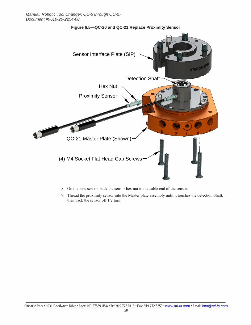
Manual, Robotic Tool Changer, QC-5 through QC-27Document #9610-20-2254-08
Pinnacle Park • 1031 Goodworth Drive • Apex, NC 27539 USA • Tel: 919.772.0115 • Fax: 919.772.8259 • www.ati-ia.com • Email: [email protected] 50
Figure 6.5—QC-20 and QC-21 Replace Proximity Sensor
Proximity Sensor
Sensor Interface Plate (SIP)
Hex Nut
(4) M4 Socket Flat Head Cap Screws
QC-21 Master Plate (Shown)
Detection Shaft
8. On the new sensor, back the sensor hex nut to the cable end of the sensor.9. Thread the proximity sensor into the Master plate assembly until it touches the detection Shaft,
then back the sensor off 1/2 turn.
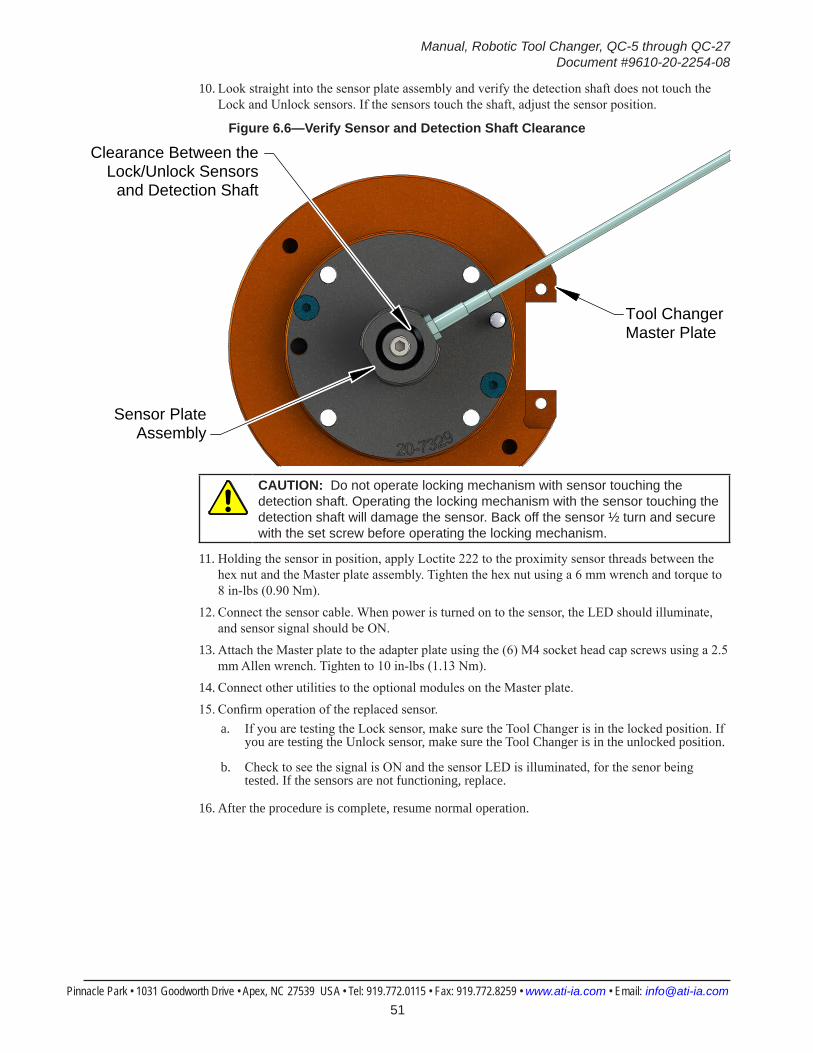
Manual, Robotic Tool Changer, QC-5 through QC-27Document #9610-20-2254-08
Pinnacle Park • 1031 Goodworth Drive • Apex, NC 27539 USA • Tel: 919.772.0115 • Fax: 919.772.8259 • www.ati-ia.com • Email: [email protected] 51
10. Look straight into the sensor plate assembly and verify the detection shaft does not touch the Lock and Unlock sensors. If the sensors touch the shaft, adjust the sensor position.
Figure 6.6—Verify Sensor and Detection Shaft Clearance
Tool Changer Master Plate
Clearance Between theLock/Unlock Sensors
and Detection Shaft
Sensor PlateAssembly
CAUTION: Do not operate locking mechanism with sensor touching the detection shaft. Operating the locking mechanism with the sensor touching the detection shaft will damage the sensor. Back off the sensor ½ turn and secure with the set screw before operating the locking mechanism.
11. Holding the sensor in position, apply Loctite 222 to the proximity sensor threads between the hex nut and the Master plate assembly. Tighten the hex nut using a 6 mm wrench and torque to 8 in-lbs (0.90 Nm).
12. Connect the sensor cable. When power is turned on to the sensor, the LED should illuminate, and sensor signal should be ON.
13. Attach the Master plate to the adapter plate using the (6) M4 socket head cap screws using a 2.5 mm Allen wrench. Tighten to 10 in-lbs (1.13 Nm).
14. Connect other utilities to the optional modules on the Master plate.15. Confirm operation of the replaced sensor.
a. If you are testing the Lock sensor, make sure the Tool Changer is in the locked position. If you are testing the Unlock sensor, make sure the Tool Changer is in the unlocked position.
b. Check to see the signal is ON and the sensor LED is illuminated, for the senor being tested. If the sensors are not functioning, replace.
16. After the procedure is complete, resume normal operation.
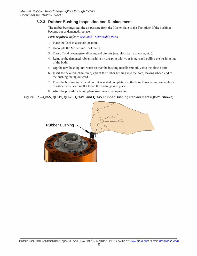
Manual, Robotic Tool Changer, QC-5 through QC-27Document #9610-20-2254-08
Pinnacle Park • 1031 Goodworth Drive • Apex, NC 27539 USA • Tel: 919.772.0115 • Fax: 919.772.8259 • www.ati-ia.com • Email: [email protected] 52
6.2.3 Rubber Bushing Inspection and ReplacementThe rubber bushings seal the air passage from the Master plate to the Tool plate. If the bushings become cut or damaged, replace.Parts required: Refer to Section 8—Serviceable Parts
1. Place the Tool in a secure location.2. Uncouple the Master and Tool plates.3. Turn off and de-energize all energized circuits (e.g. electrical, air, water, etc.).4. Remove the damaged rubber bushing by grasping with your fingers and pulling the bushing out
of the body.5. Dip the new bushing into water so that the bushing installs smoothly into the plate’s bore.6. Insert the beveled (chamfered) end of the rubber bushing into the bore, leaving ribbed end of
the bushing facing outward.7. Press the bushing in by hand until it is seated completely in the bore. If necessary, use a plastic
or rubber soft-faced mallet to tap the bushings into place.8. After the procedure is complete, resume normal operation.
Figure 6.7 —QC-5, QC-11, QC-20, QC-21, and QC-27 Rubber Bushing Replacement (QC-21 Shown)
Rubber Bushing
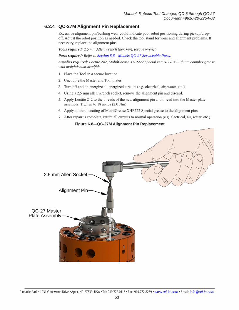
Manual, Robotic Tool Changer, QC-5 through QC-27Document #9610-20-2254-08
Pinnacle Park • 1031 Goodworth Drive • Apex, NC 27539 USA • Tel: 919.772.0115 • Fax: 919.772.8259 • www.ati-ia.com • Email: [email protected] 53
6.2.4 QC-27M Alignment Pin ReplacementExcessive alignment pin/bushing wear could indicate poor robot positioning during pickup/drop-off. Adjust the robot position as needed. Check the tool stand for wear and alignment problems. If necessary, replace the alignment pins.Tools required: 2.5 mm Allen wrench (hex key), torque wrenchParts required: Refer to Section 8.6—Models QC-27 Serviceable Parts.Supplies required: Loctite 242, MobilGrease XHP222 Special is a NLGI #2 lithium complex grease with molybdenum disulfide
1. Place the Tool in a secure location.2. Uncouple the Master and Tool plates.3. Turn off and de-energize all energized circuits (e.g. electrical, air, water, etc.).4. Using a 2.5 mm allen wrench socket, remove the alignment pin and discard.5. Apply Loctite 242 to the threads of the new alignment pin and thread into the Master plate
assembly. Tighten to 18 in-lbs (2.0 Nm).6. Apply a liberal coating of MobilGrease XHP222 Special grease to the alignment pins.7. After repair is complete, return all circuits to normal operation (e.g. electrical, air, water, etc.).
Figure 6.8—QC-27M Alignment Pin Replacement
2.5 mm Allen Socket
Alignment Pin
QC-27 Master Plate Assembly
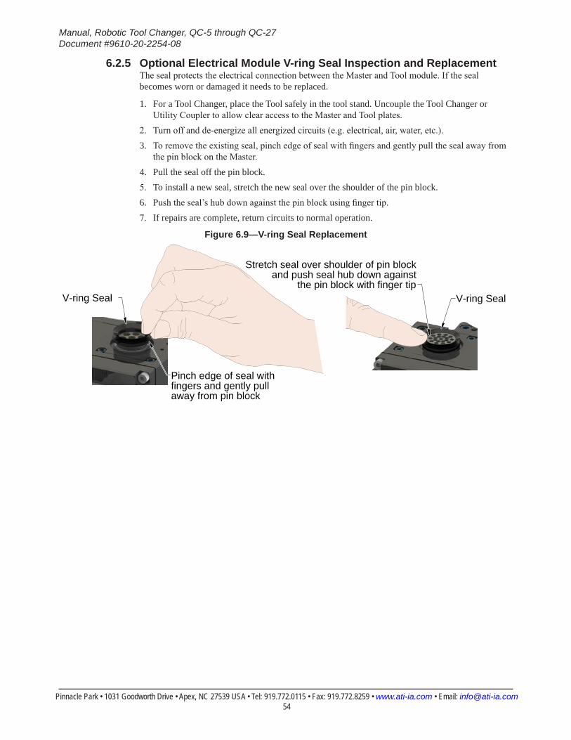
Manual, Robotic Tool Changer, QC-5 through QC-27Document #9610-20-2254-08
Pinnacle Park • 1031 Goodworth Drive • Apex, NC 27539 USA • Tel: 919.772.0115 • Fax: 919.772.8259 • www.ati-ia.com • Email: [email protected] 54
6.2.5 Optional Electrical Module V-ring Seal Inspection and ReplacementThe seal protects the electrical connection between the Master and Tool module. If the seal becomes worn or damaged it needs to be replaced.
1. For a Tool Changer, place the Tool safely in the tool stand. Uncouple the Tool Changer or Utility Coupler to allow clear access to the Master and Tool plates.
2. Turn off and de-energize all energized circuits (e.g. electrical, air, water, etc.). 3. To remove the existing seal, pinch edge of seal with fingers and gently pull the seal away from
the pin block on the Master.4. Pull the seal off the pin block.5. To install a new seal, stretch the new seal over the shoulder of the pin block.6. Push the seal’s hub down against the pin block using finger tip.7. If repairs are complete, return circuits to normal operation.
Figure 6.9—V-ring Seal Replacement
V-ring Seal
Stretch seal over shoulder of pin block and push seal hub down against
the pin block with finger tipV-ring Seal
Pinch edge of seal with fingers and gently pull away from pin block
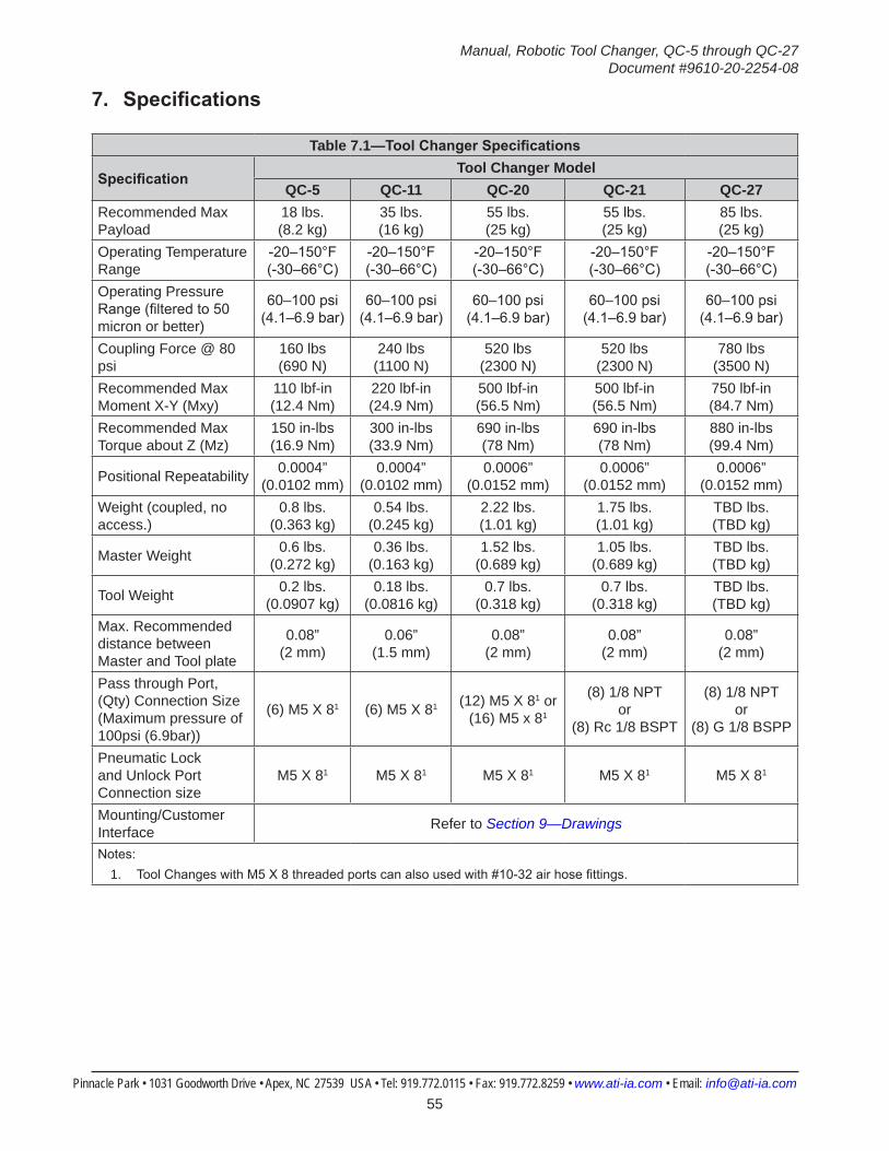
Manual, Robotic Tool Changer, QC-5 through QC-27Document #9610-20-2254-08
Pinnacle Park • 1031 Goodworth Drive • Apex, NC 27539 USA • Tel: 919.772.0115 • Fax: 919.772.8259 • www.ati-ia.com • Email: [email protected] 55
7. Specifications
Table 7.1—ToolChangerSpecifications
SpecificationTool Changer Model
QC-5 QC-11 QC-20 QC-21 QC-27Recommended Max Payload
18 lbs. (8.2 kg)
35 lbs. (16 kg)
55 lbs. (25 kg)
55 lbs. (25 kg)
85 lbs. (25 kg)
Operating Temperature Range
-20–150°F(-30–66°C)
-20–150°F(-30–66°C)
-20–150°F(-30–66°C)
-20–150°F(-30–66°C)
-20–150°F(-30–66°C)
Operating Pressure Range (filtered to 50 micron or better)
60–100 psi(4.1–6.9 bar)
60–100 psi(4.1–6.9 bar)
60–100 psi(4.1–6.9 bar)
60–100 psi(4.1–6.9 bar)
60–100 psi(4.1–6.9 bar)
Coupling Force @ 80 psi
160 lbs(690 N)
240 lbs(1100 N)
520 lbs(2300 N)
520 lbs(2300 N)
780 lbs(3500 N)
Recommended Max Moment X-Y (Mxy)
110 lbf-in(12.4 Nm)
220 lbf-in(24.9 Nm)
500 lbf-in(56.5 Nm)
500 lbf-in(56.5 Nm)
750 lbf-in(84.7 Nm)
Recommended Max Torque about Z (Mz)
150 in-lbs(16.9 Nm)
300 in-lbs(33.9 Nm)
690 in-lbs(78 Nm)
690 in-lbs(78 Nm)
880 in-lbs(99.4 Nm)
Positional Repeatability 0.0004”(0.0102 mm)
0.0004”(0.0102 mm)
0.0006”(0.0152 mm)
0.0006”(0.0152 mm)
0.0006”(0.0152 mm)
Weight (coupled, no access.)
0.8 lbs. (0.363 kg)
0.54 lbs. (0.245 kg)
2.22 lbs. (1.01 kg)
1.75 lbs. (1.01 kg)
TBD lbs. (TBD kg)
Master Weight 0.6 lbs. (0.272 kg)
0.36 lbs. (0.163 kg)
1.52 lbs. (0.689 kg)
1.05 lbs. (0.689 kg)
TBD lbs. (TBD kg)
Tool Weight 0.2 lbs. (0.0907 kg)
0.18 lbs. (0.0816 kg)
0.7 lbs. (0.318 kg)
0.7 lbs. (0.318 kg)
TBD lbs. (TBD kg)
Max. Recommended distance between Master and Tool plate
0.08”(2 mm)
0.06”(1.5 mm)
0.08”(2 mm)
0.08”(2 mm)
0.08”(2 mm)
Pass through Port, (Qty) Connection Size (Maximum pressure of 100psi (6.9bar))
(6) M5 X 81 (6) M5 X 81 (12) M5 X 81 or (16) M5 x 81
(8) 1/8 NPT or
(8) Rc 1/8 BSPT
(8) 1/8 NPT or
(8) G 1/8 BSPP
Pneumatic Lock and Unlock Port Connection size
M5 X 81 M5 X 81 M5 X 81 M5 X 81 M5 X 81
Mounting/Customer Interface Refer to Section 9—Drawings
Notes:1. Tool Changes with M5 X 8 threaded ports can also used with #10-32 air hose fittings.
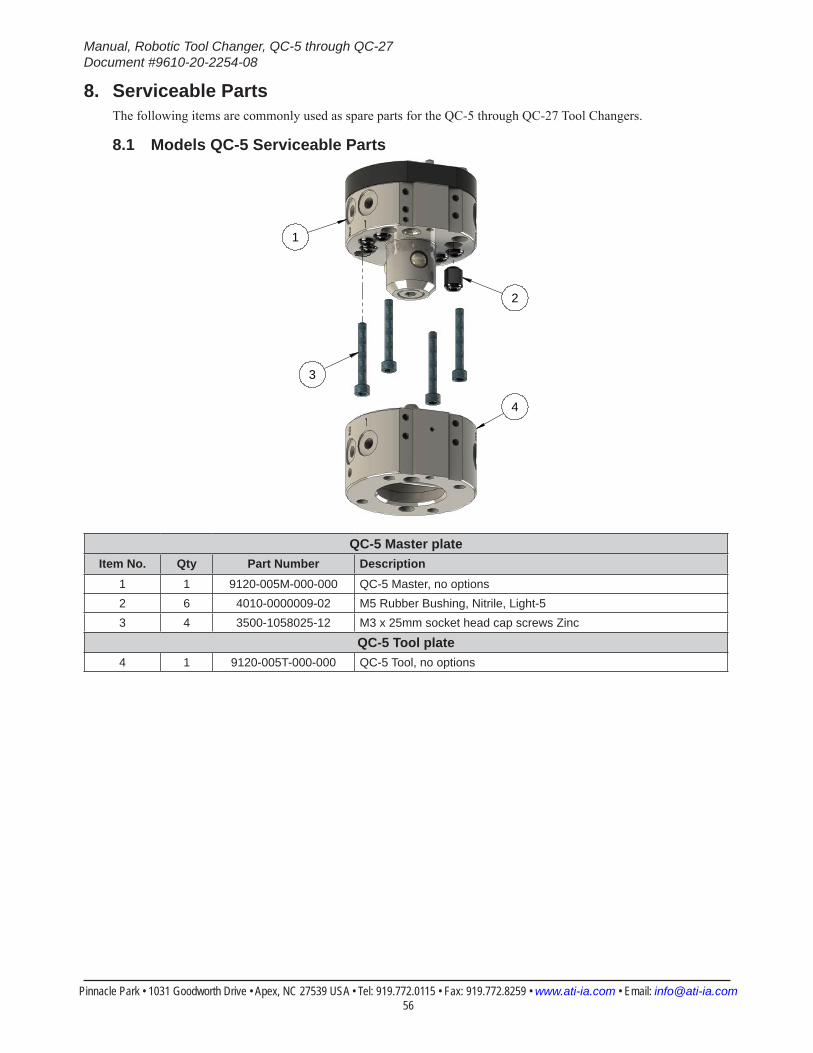
Manual, Robotic Tool Changer, QC-5 through QC-27Document #9610-20-2254-08
Pinnacle Park • 1031 Goodworth Drive • Apex, NC 27539 USA • Tel: 919.772.0115 • Fax: 919.772.8259 • www.ati-ia.com • Email: [email protected] 56
8. Serviceable PartsThe following items are commonly used as spare parts for the QC-5 through QC-27 Tool Changers.
8.1 Models QC-5 Serviceable Parts
3
2
1
4
QC-5 Master plateItem No. Qty Part Number Description
1 1 9120-005M-000-000 QC-5 Master, no options2 6 4010-0000009-02 M5 Rubber Bushing, Nitrile, Light-53 4 3500-1058025-12 M3 x 25mm socket head cap screws Zinc
QC-5 Tool plate4 1 9120-005T-000-000 QC-5 Tool, no options
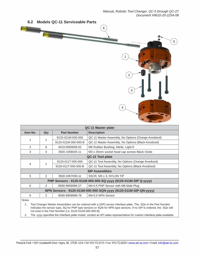
Manual, Robotic Tool Changer, QC-5 through QC-27Document #9610-20-2254-08
Pinnacle Park • 1031 Goodworth Drive • Apex, NC 27539 USA • Tel: 919.772.0115 • Fax: 919.772.8259 • www.ati-ia.com • Email: [email protected] 57
8.2 Models QC-11 Serviceable Parts
3
2
6
5
4
1
QC-11 Master plateItem No. Qty Part Number Description
1 19120-011M-000-000 QC-11 Master Assembly, No Options (Orange Anodized)
9120-011M-000-000-B QC-11 Master Assembly, No Options (Black Anodized)2 6 4010-0000009-02 M5 Rubber Bushing, Nitrile, Light-53 4 3500-1058025-11 M3 x 25mm socket head cap screws Black Oxide
QC-11 Tool plate
4 19120-011T-000-000 QC-11 Tool Assembly, No Options (Orange Anodized)
9120-011T-000-000-B QC-11 Tool Assembly, No Options (Black Anodized)
SIP Assemblies5 2 3500-1957030-11 SSCR, M3 x 3, NYLON TIP
PNP Sensors - 9120-011M-000-000-SQ-yyyy (9120-011M-SIP Q-yyyy)6 2 8590-9909999-27 M4-0.5 PNP Sensor with M8 Male Plug
NPN Sensors - 9120-011M-000-000-SQN-yyyy (9120-011M-SIP-QN-yyyy)6 2 8590-9909999-78 M4-0.5 NPN Sensor
Notes:
1. Tool Changer Master Assemblies can be ordered with a (SIP) sensor interface plate. The -SQx in the Part Number indicates the sensor type, SQ for PNP type sensors or SQN for NPN type sensors. If no SIP is ordered, the -SQx will not exist in the Part Number (i.e. 9120-011M-000-000-B).
2. The -yyyy specifies the Interface plate model, contact an ATI sales representative for custom interface plate available.
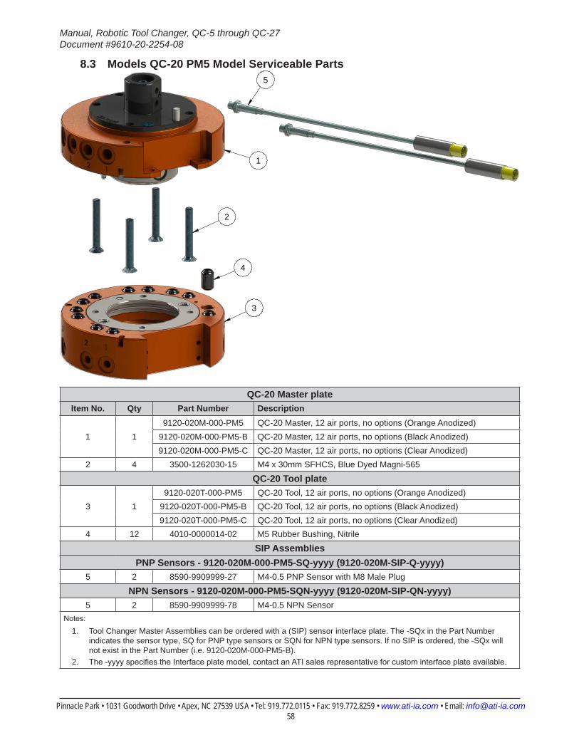
Manual, Robotic Tool Changer, QC-5 through QC-27Document #9610-20-2254-08
Pinnacle Park • 1031 Goodworth Drive • Apex, NC 27539 USA • Tel: 919.772.0115 • Fax: 919.772.8259 • www.ati-ia.com • Email: [email protected] 58
8.3 Models QC-20 PM5 Model Serviceable Parts5
2
4
1
3
QC-20 Master plateItem No. Qty Part Number Description
1 19120-020M-000-PM5 QC-20 Master, 12 air ports, no options (Orange Anodized)
9120-020M-000-PM5-B QC-20 Master, 12 air ports, no options (Black Anodized)9120-020M-000-PM5-C QC-20 Master, 12 air ports, no options (Clear Anodized)
2 4 3500-1262030-15 M4 x 30mm SFHCS, Blue Dyed Magni-565
QC-20 Tool plate
3 19120-020T-000-PM5 QC-20 Tool, 12 air ports, no options (Orange Anodized)
9120-020T-000-PM5-B QC-20 Tool, 12 air ports, no options (Black Anodized)9120-020T-000-PM5-C QC-20 Tool, 12 air ports, no options (Clear Anodized)
4 12 4010-0000014-02 M5 Rubber Bushing, Nitrile
SIP AssembliesPNP Sensors - 9120-020M-000-PM5-SQ-yyyy (9120-020M-SIP-Q-yyyy)
5 2 8590-9909999-27 M4-0.5 PNP Sensor with M8 Male Plug
NPN Sensors - 9120-020M-000-PM5-SQN-yyyy (9120-020M-SIP-QN-yyyy)5 2 8590-9909999-78 M4-0.5 NPN Sensor
Notes:
1. Tool Changer Master Assemblies can be ordered with a (SIP) sensor interface plate. The -SQx in the Part Number indicates the sensor type, SQ for PNP type sensors or SQN for NPN type sensors. If no SIP is ordered, the -SQx will not exist in the Part Number (i.e. 9120-020M-000-PM5-B).
2. The -yyyy specifies the Interface plate model, contact an ATI sales representative for custom interface plate available.
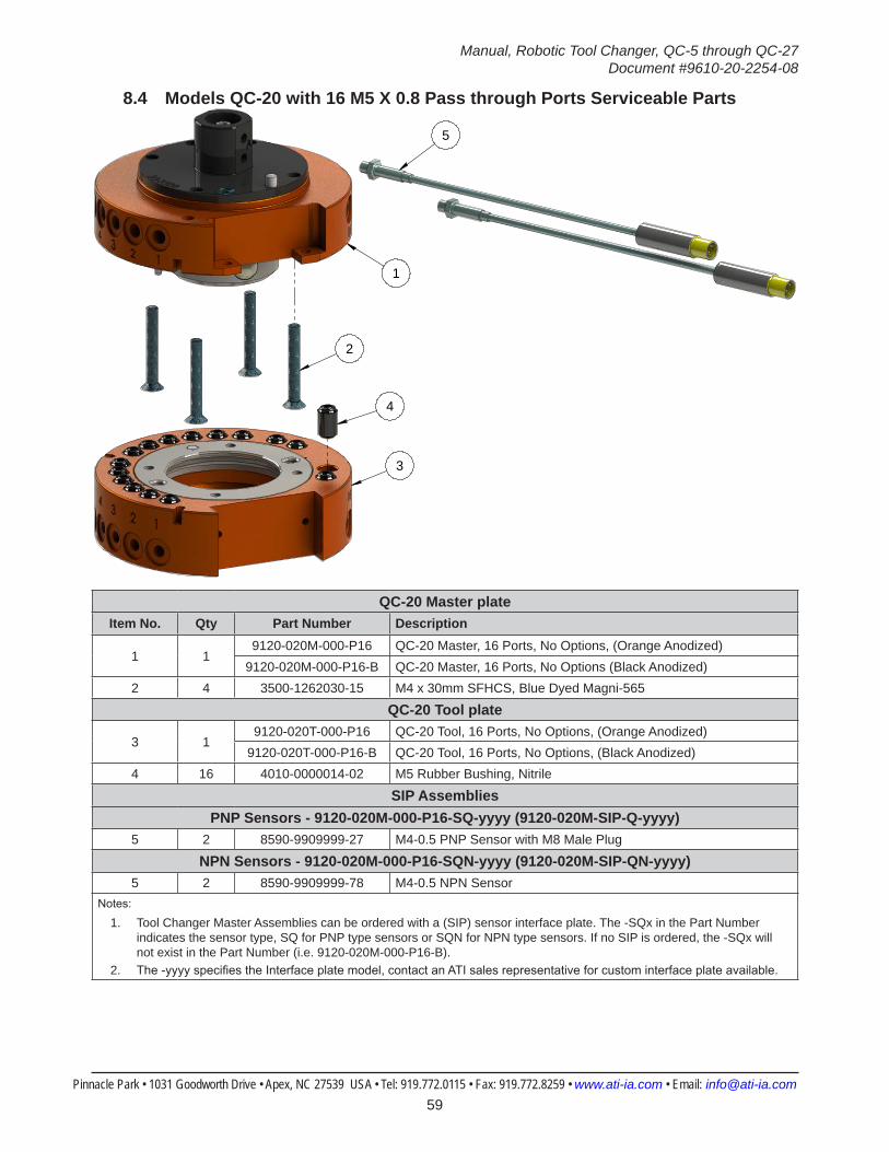
Manual, Robotic Tool Changer, QC-5 through QC-27Document #9610-20-2254-08
Pinnacle Park • 1031 Goodworth Drive • Apex, NC 27539 USA • Tel: 919.772.0115 • Fax: 919.772.8259 • www.ati-ia.com • Email: [email protected] 59
8.4 Models QC-20 with 16 M5 X 0.8 Pass through Ports Serviceable Parts
5
1
2
4
3
QC-20 Master plateItem No. Qty Part Number Description
1 19120-020M-000-P16 QC-20 Master, 16 Ports, No Options, (Orange Anodized)
9120-020M-000-P16-B QC-20 Master, 16 Ports, No Options (Black Anodized)2 4 3500-1262030-15 M4 x 30mm SFHCS, Blue Dyed Magni-565
QC-20 Tool plate
3 19120-020T-000-P16 QC-20 Tool, 16 Ports, No Options, (Orange Anodized)
9120-020T-000-P16-B QC-20 Tool, 16 Ports, No Options, (Black Anodized)4 16 4010-0000014-02 M5 Rubber Bushing, Nitrile
SIP AssembliesPNP Sensors - 9120-020M-000-P16-SQ-yyyy (9120-020M-SIP-Q-yyyy)
5 2 8590-9909999-27 M4-0.5 PNP Sensor with M8 Male Plug
NPN Sensors - 9120-020M-000-P16-SQN-yyyy (9120-020M-SIP-QN-yyyy)5 2 8590-9909999-78 M4-0.5 NPN Sensor
Notes:
1. Tool Changer Master Assemblies can be ordered with a (SIP) sensor interface plate. The -SQx in the Part Number indicates the sensor type, SQ for PNP type sensors or SQN for NPN type sensors. If no SIP is ordered, the -SQx will not exist in the Part Number (i.e. 9120-020M-000-P16-B).
2. The -yyyy specifies the Interface plate model, contact an ATI sales representative for custom interface plate available.
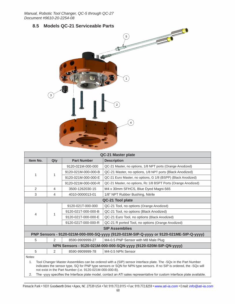
Manual, Robotic Tool Changer, QC-5 through QC-27Document #9610-20-2254-08
Pinnacle Park • 1031 Goodworth Drive • Apex, NC 27539 USA • Tel: 919.772.0115 • Fax: 919.772.8259 • www.ati-ia.com • Email: [email protected] 60
8.5 Models QC-21 Serviceable Parts
2
3
5
1
4
QC-21 Master plateItem No. Qty Part Number Description
1 1
9120-021M-000-000 QC-21 Master, no options, 1/8 NPT ports (Orange Anodized)
9120-021M-000-000-B QC-21 Master, no options, 1/8 NPT ports (Black Anodized)9120-021M-000-000-E QC-21 Euro Master, no options, G 1/8 (BSPP) (Black Anodized)
9120-021M-000-000-R QC-21 Master, no options, Rc 1/8 BSPT Ports (Orange Anodized)
2 4 3500-1262030-15 M4 x 30mm SFHCS, Blue Dyed Magni-5653 4 4010-0000013-01 1/8” NPT Rubber Bushing, Nitrile
QC-21 Tool plate
4 1
9120-021T-000-000 QC-21 Tool, no options (Orange Anodized)
9120-021T-000-000-B QC-21 Tool, no options (Black Anodized)9120-021T-000-000-E QC-21 Euro Tool, no options (Black Anodized)
9120-021T-000-000-R QC-21 R ported Tool, no options (Orange Anodized)
SIP AssembliesPNP Sensors - 9120-021M-000-000-SQ-yyyy (9120-021M-SIP-Q-yyyy or 9120-021ME-SIP-Q-yyyy)
5 2 8590-9909999-27 M4-0.5 PNP Sensor with M8 Male Plug
NPN Sensors - 9120-021M-000-000-SQN-yyyy (9120-020M-SIP-QN-yyyy)5 2 8590-9909999-78 M4-0.5 NPN Sensor
Notes:
1. Tool Changer Master Assemblies can be ordered with a (SIP) sensor interface plate. The -SQx in the Part Number indicates the sensor type, SQ for PNP type sensors or SQN for NPN type sensors. If no SIP is ordered, the -SQx will not exist in the Part Number (i.e. 9120-021M-000-000-B).
2. The -yyyy specifies the Interface plate model, contact an ATI sales representative for custom interface plate available.
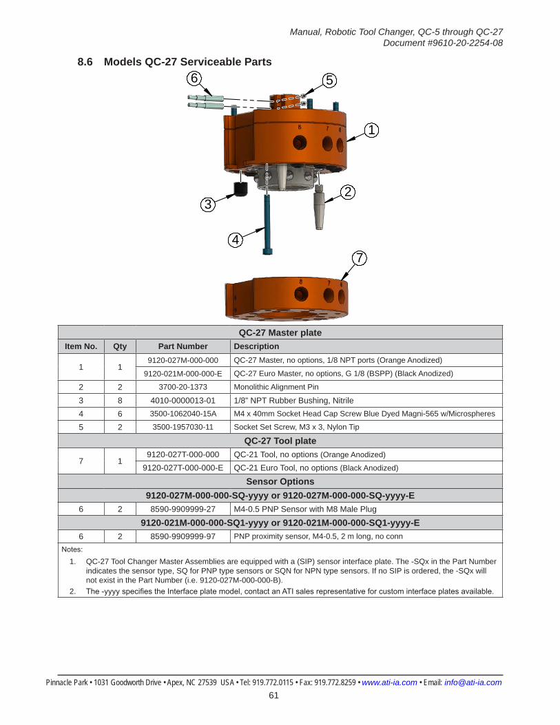
Manual, Robotic Tool Changer, QC-5 through QC-27Document #9610-20-2254-08
Pinnacle Park • 1031 Goodworth Drive • Apex, NC 27539 USA • Tel: 919.772.0115 • Fax: 919.772.8259 • www.ati-ia.com • Email: [email protected] 61
8.6 Models QC-27 Serviceable Parts6 5
2
1
3
47
QC-27 Master plateItem No. Qty Part Number Description
1 19120-027M-000-000 QC-27 Master, no options, 1/8 NPT ports (Orange Anodized)
9120-021M-000-000-E QC-27 Euro Master, no options, G 1/8 (BSPP) (Black Anodized)
2 2 3700-20-1373 Monolithic Alignment Pin
3 8 4010-0000013-01 1/8” NPT Rubber Bushing, Nitrile4 6 3500-1062040-15A M4 x 40mm Socket Head Cap Screw Blue Dyed Magni-565 w/Microspheres
5 2 3500-1957030-11 Socket Set Screw, M3 x 3, Nylon Tip
QC-27 Tool plate
7 19120-027T-000-000 QC-21 Tool, no options (Orange Anodized)
9120-027T-000-000-E QC-21 Euro Tool, no options (Black Anodized)
Sensor Options9120-027M-000-000-SQ-yyyy or 9120-027M-000-000-SQ-yyyy-E
6 2 8590-9909999-27 M4-0.5 PNP Sensor with M8 Male Plug
9120-021M-000-000-SQ1-yyyy or 9120-021M-000-000-SQ1-yyyy-E6 2 8590-9909999-97 PNP proximity sensor, M4-0.5, 2 m long, no conn
Notes:
1. QC-27 Tool Changer Master Assemblies are equipped with a (SIP) sensor interface plate. The -SQx in the Part Number indicates the sensor type, SQ for PNP type sensors or SQN for NPN type sensors. If no SIP is ordered, the -SQx will not exist in the Part Number (i.e. 9120-027M-000-000-B).
2. The -yyyy specifies the Interface plate model, contact an ATI sales representative for custom interface plates available.
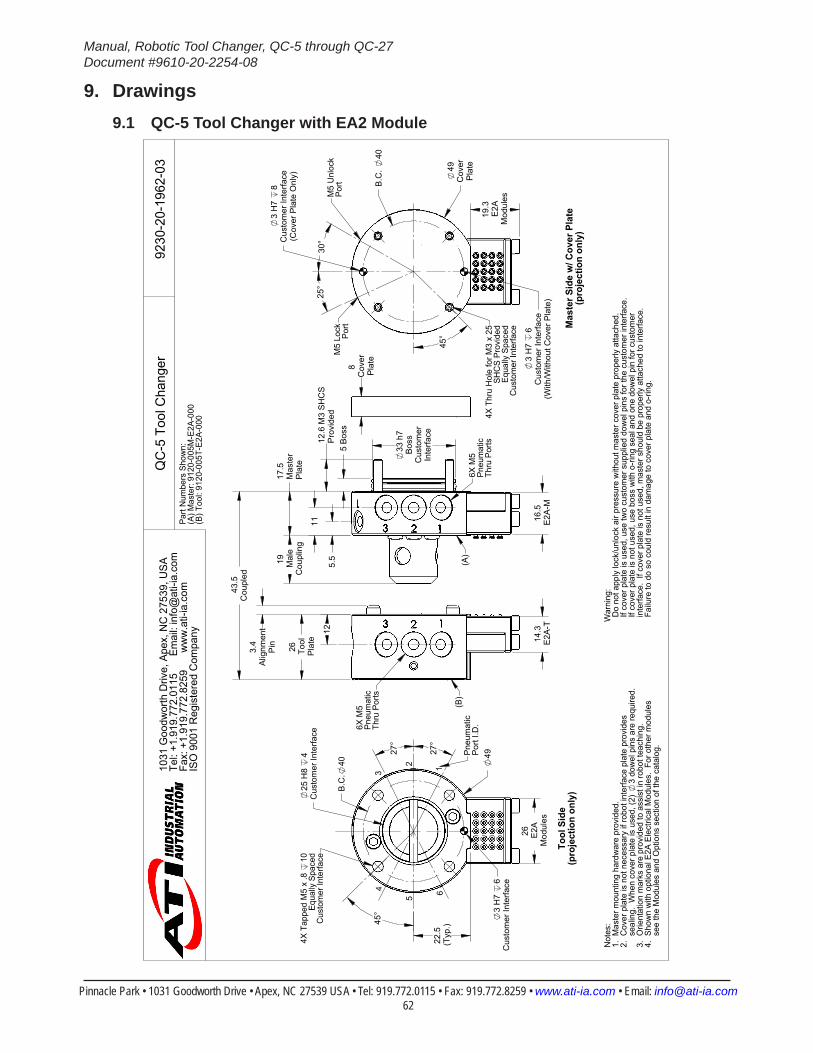
Manual, Robotic Tool Changer, QC-5 through QC-27Document #9610-20-2254-08
Pinnacle Park • 1031 Goodworth Drive • Apex, NC 27539 USA • Tel: 919.772.0115 • Fax: 919.772.8259 • www.ati-ia.com • Email: [email protected] 62
9. Drawings9.1 QC-5 Tool Changer with EA2 Module
49
22.5
(Typ
.)
25 H
8 4
Cus
tom
er In
terfa
ce
3 H
7 6
Cus
tom
er In
terfa
ce
26 E2A
Mod
ules
B.C
.40
45°
27°
27°
4X T
appe
d M
5 x
.8
10Eq
ually
Spa
ced
Cus
tom
er In
terfa
ce
12
34
5 6
Pne
umat
icP
ort I
.D.
Tool
Sid
e(p
roje
ctio
n on
ly)
26 Tool
Pla
te
19 Mal
eC
oupl
ing
14.3
E2A
-T16
.5E
2A-M
17.5
Mas
ter
Pla
te
Cou
pled
43.5
33 h
7B
oss
Cus
tom
erIn
terfa
ce
5 B
oss
8 C
over
Pla
te
3.4
Alig
nmen
tP
in
12.6
M3
SH
CS
Pro
vide
d12
5.5
11
6X M
5Pn
eum
atic
Thru
Por
ts
6X M
5Pn
eum
atic
Thru
Por
ts
(A)
(B)
19.3
E2A
Mod
ules
B.C
. 40
49C
over
Pla
te
3 H
7 6
Cus
tom
er In
terfa
ce(W
ith/W
ithou
t Cov
er P
late
)
3 H
7 8
Cus
tom
er In
terfa
ce(C
over
Pla
te O
nly)
45°
25°
3
0°
4X T
hru
Hol
e fo
r M3
x 25
SHC
S Pr
ovid
edEq
ually
Spa
ced
Cus
tom
er In
terfa
ce
M5
Lock
Port
M5
Unl
ock
Port
Mas
ter S
ide
w/ C
over
Pla
te(p
roje
ctio
n on
ly)
Part
Num
bers
Sho
wn:
(A) M
aste
r: 91
20-0
05M
-E2A
-000
(B) T
ool:
9120
-005
T-E2
A-00
0
Not
es:
1. M
aste
r mou
ntin
g ha
rdw
are
prov
ided
.2.
Cov
er p
late
is n
ot n
eces
sary
if ro
bot i
nter
face
pla
te p
rovi
des
s
ealin
g. W
hen
cove
r pla
te is
use
d, (2
) 3
dow
el p
ins
are
requ
ired.
3.
Orie
ntat
ion
mar
ks a
re p
rovi
ded
to a
ssis
t in
robo
t tea
chin
g.4.
Sho
wn
with
opt
iona
l E2A
Ele
ctric
al M
odul
es.
For o
ther
mod
ules
see
the
Mod
ules
and
Opt
ions
sec
tion
of th
e ca
talo
g.
War
ning
: D
o no
t app
ly lo
ck/u
nloc
k ai
r pre
ssur
e w
ithou
t mas
ter c
over
pla
te p
rope
rly a
ttach
ed.
If c
over
pla
te is
use
d, u
se tw
o cu
stom
er s
uppl
ied
dow
el p
ins
for t
he c
usto
mer
inte
rface
. I
f cov
er p
late
is n
ot u
sed,
use
bos
s w
ith o
-ring
sea
l and
one
dow
el p
in fo
r cus
tom
er i
nter
face
. If
cove
r pla
te is
not
use
d, m
aste
r sho
uld
be p
rope
rly a
ttach
ed to
inte
rface
. F
ailu
re to
do
so c
ould
resu
lt in
dam
age
to c
over
pla
te a
nd o
-ring
.
QC
-5 T
ool C
hang
er92
30-2
0-19
62-0
310
31 G
oodw
orth
Driv
e, A
pex,
NC
275
39, U
SATe
l: +1
.919
.772
.011
5
Em
ail:
info
@at
i-ia.
com
Fax:
+1.
919.
772.
8259
ww
w.a
ti-ia
.com
ISO
900
1 R
egis
tere
d C
ompa
ny
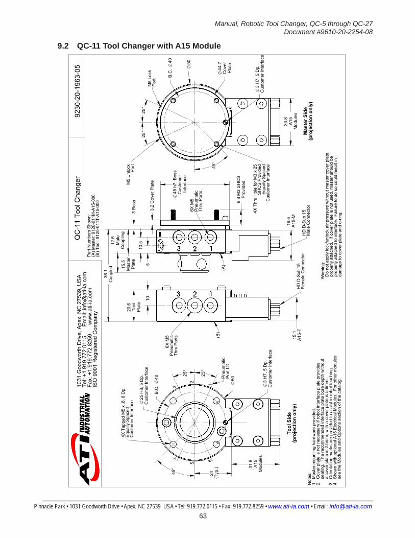
Manual, Robotic Tool Changer, QC-5 through QC-27Document #9610-20-2254-08
Pinnacle Park • 1031 Goodworth Drive • Apex, NC 27539 USA • Tel: 919.772.0115 • Fax: 919.772.8259 • www.ati-ia.com • Email: [email protected] 63
9.2 QC-11 Tool Changer with A15 Module
25 H
8, 5
Dp.
Cus
tom
er In
terfa
ce
3 H
7, 5
Dp.
Cus
tom
er In
terfa
ce
50
24 (Typ
.) 31.5
A15
Mod
ules
B.C
. 40
45°
25°
25°
4X T
appe
d M
5 x
.8, 8
Dp.
Equa
lly S
pace
dC
usto
mer
Inte
rface
2
3
65
4
Tool
Sid
e(p
roje
ctio
n on
ly)
Pne
umat
icP
ort I
.D.
1
20.6
Tool
Pla
te
12.5
Mal
eC
oupl
ing
3.2
Cov
er P
late
Cou
pled
36.1
15.1
A15
-T
19.6
A15
-M
45 h
7, B
oss
Cus
tom
er
Inte
rface
15.5
Mas
ter
Pla
te
9.8
M3
SH
CS
Pro
vide
d
3 B
oss
105
10.5
6X M
5Pn
eum
atic
Thru
Por
ts
(A)
(B)
HD
D-S
ub 1
5Fe
mal
e C
onne
ctor
HD
D-S
ub 1
5M
ale
Con
nect
or6X M
5P
neum
atic
Thru
Por
ts
44.7
Cov
erP
late
3 H
7, 5
Dp.
Cus
tom
er In
terfa
ce
30.8
A15
Mod
ules
50
B.C
. 40
25°
25°
45°
4X T
hru
Hol
e fo
r M3
x 25
SHC
S Pr
ovid
edEq
ually
Spa
ced
Cus
tom
er In
terfa
ce
M5
Unl
ock
Port
M5
Lock
Port
Mas
ter S
ide
(pro
ject
ion
only
)
Part
Num
bers
Sho
wn:
(A) M
aste
r: 91
20-0
11M
-A15
-000
(B) T
ool:
9120
-011
T-A1
5-00
0
Not
es:
1. M
aste
r mou
ntin
g ha
rdw
are
prov
ided
.2.
Cov
er p
late
is n
ot n
eces
sary
if ro
bot i
nter
face
pla
te p
rovi
des
s
ealin
g. T
he re
com
men
ded
inte
rface
pla
te b
ore
dept
h w
ithou
t
a c
over
pla
te is
2.5
mm
, with
a c
over
pla
te is
5.6
mm
.3.
Orie
ntat
ion
mar
ks a
re p
rovi
ded
to a
ssis
t in
robo
t tea
chin
g.4.
Sho
wn
with
opt
iona
l A15
Ele
ctric
al M
odul
es.
For o
ther
mod
ules
s
ee th
e M
odul
es a
nd O
ptio
ns s
ectio
n of
the
cata
log.
War
ning
: D
o no
t app
ly lo
ck/u
nloc
k ai
r pre
ssur
e w
ithou
t mas
ter c
over
pla
te p
rope
rly a
ttach
ed.
If co
ver p
late
is n
ot u
sed,
mas
ter s
houl
d be
p
rope
rly a
ttach
ed to
inte
rface
. Fa
ilure
to d
o so
cou
ld re
sult
in
dam
age
to c
over
pla
te a
nd o
-ring
.
QC
-11
Tool
Cha
nger
9230
-20-
1963
-05
1031
Goo
dwor
th D
rive,
Ape
x, N
C 2
7539
, USA
Tel:
+1.9
19.7
72.0
115
E
mai
l: in
fo@
ati-i
a.co
mFa
x: +
1.91
9.77
2.82
59
w
ww
.ati-
ia.c
omIS
O 9
001
Reg
iste
red
Com
pany
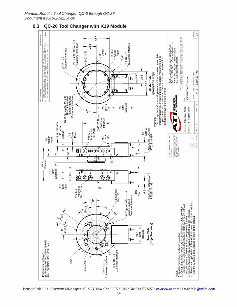
Manual, Robotic Tool Changer, QC-5 through QC-27Document #9610-20-2254-08
Pinnacle Park • 1031 Goodworth Drive • Apex, NC 27539 USA • Tel: 919.772.0115 • Fax: 919.772.8259 • www.ati-ia.com • Email: [email protected] 64
9.3 QC-20 Tool Changer with K19 Module
3rd
AN
GLE
PRO
JEC
TION
90
39.8
K19
Mod
ules
40 H
7 6
Cus
tom
er In
terfa
ce
6 H
7 10
Cus
tom
er In
terfa
ce
B.C
.63
17°
(Typ
.)
17°
(Typ
.)
17°
(Typ
.)
17°
(Typ
.)
45°
4X T
appe
d M
6x1
10Eq
ually
Spa
ced
Cus
tom
er In
terfa
ce
1
23
4
56
78
9
10 11
12
Tool
Sid
e(p
roje
ctio
n on
ly)
Pne
umat
icP
ort I
.D.
23.7
Tool
Pla
te
30.6
K19
-M
12
3 B
oss
Cou
pled
42.4
60 h
7, B
oss
Cus
tom
erIn
terfa
ce
18.7
Mas
ter
Pla
te13
.5M
ale
Cou
plin
g
30.6
K19
-T
6.9
9 M
4 S
FHC
SP
rovi
ded
3.2
Cov
erP
late
16.7
12
M5
Lock
Po
rt
Amph
enol
Con
nect
orPT
02E-
14-1
9PAm
phen
ol C
onne
ctor
PT02
E-14
-19S
(A)
(B)
12X
M5
Pne
umat
icTh
ru P
orts
12X
M5
Pne
umat
icTh
ru P
orts
50 K19
Mod
ules
33 (Typ
.)
90
28.
8
57.
5
26.
3
52.
7
58.4
Cov
erP
late
4 H
7 7
Cus
tom
er In
terfa
ce
4 H
7 7
Cus
tom
er In
terfa
ce
2X
4 S
F D
owel
6
Cus
tom
er In
terfa
ce
B.C
. 53
15°
45°
4X T
hru
Hol
e fo
r M4x
30SF
HC
S Pr
ovid
edEq
ually
Spa
ced
Cus
tom
er In
terfa
ce
M5
Unl
ock
Port
Mas
ter S
ide
(pro
ject
ion
only
)
Not
es:
1. M
aste
r mou
ntin
g ha
rdw
are
prov
ided
.2.
Cov
er p
late
is n
ot n
eces
sary
if ro
bot i
nter
face
pla
te p
rovi
des
s
ealin
g. T
he re
com
men
ded
inte
rface
pla
te b
ore
dept
h w
ithou
t
a c
over
pla
te is
2.5
mm
, with
a c
over
pla
te is
5.6
mm
.3.
Orie
ntat
ion
mar
ks a
re p
rovi
ded
to a
ssis
t in
robo
t tea
chin
g.4.
Sho
wn
with
opt
iona
l K19
Ele
ctric
al M
odul
es.
For o
ther
mod
ules
s
ee th
e M
odul
es a
nd O
ptio
ns s
ectio
n of
the
cata
log.
Part
Num
bers
Sho
wn:
(A) M
aste
r: 91
20-0
20M
-K19
-PM
5(B
) Too
l: 91
20-0
20T-
K19-
PM5
War
ning
: D
o no
t app
ly lo
ck/u
nloc
k ai
r pre
ssur
e w
ithou
t mas
ter c
over
pla
te p
rope
rly a
ttach
ed.
If co
ver p
late
is n
ot u
sed,
mas
ter s
houl
d be
p
rope
rly a
ttach
ed to
inte
rface
. Fa
ilure
to d
o so
cou
ld re
sult
in
dam
age
to c
over
pla
te a
nd o
-ring
.
Rev.
Des
crip
tion
Initi
ator
Dat
e
04EC
O 1
4321
; Mas
ter S
ide
- 2
loca
tions
4
H7
7 w
as
4 (d
owel
ho
le fa
rthes
t fro
m m
odul
e) a
nd
14 (d
owel
hol
e cl
oses
t to
mod
ule)
. Upd
ated
Titl
e Bl
ock
and
fille
d in
"Che
cked
By:
" fie
ldSZ
J4/
26/2
016
B1:
1.3
11
REVI
SIO
N
NO
TES:
UN
LESS
OTH
ERW
ISE
SPEC
IFIE
D.
DO
NO
T SC
ALE
DRA
WIN
G.
ALL
DIM
ENSI
ON
S A
RE IN
M
ILLIM
ETER
S.
DRA
WN
BY:
CHE
CKE
D B
Y:
P.Sp
arro
w, 7
/22/
04
D. W
agne
r, 5/
2/16
TITLE SC
ALE
SIZE
DRA
WIN
G N
UMBE
R
PRO
JEC
T #
SHEE
T
O
F 92
30-2
0-19
64
04
PRO
PERT
Y O
F A
TI IN
DUS
TRIA
L A
UTO
MA
TION
, IN
C. N
OT
TO B
E RE
PRO
DUC
ED IN
AN
Y M
AN
NER
EXC
EPT
ON
ORD
ER O
R W
ITH P
RIO
R W
RITT
EN A
UTHO
RIZA
TION
OF
ATI.
1031
Goo
dwor
th Dr
ive, A
pex,
NC 27
539,
USA
Tel: +
1.919
.772.0
115
Em
ail: in
fo@ati
-ia.co
mFa
x: +1
.919.7
72.82
59
www
.ati-ia
.com
ISO
9001
Reg
ister
ed C
ompa
ny
QC
-20
Tool
Cha
nger
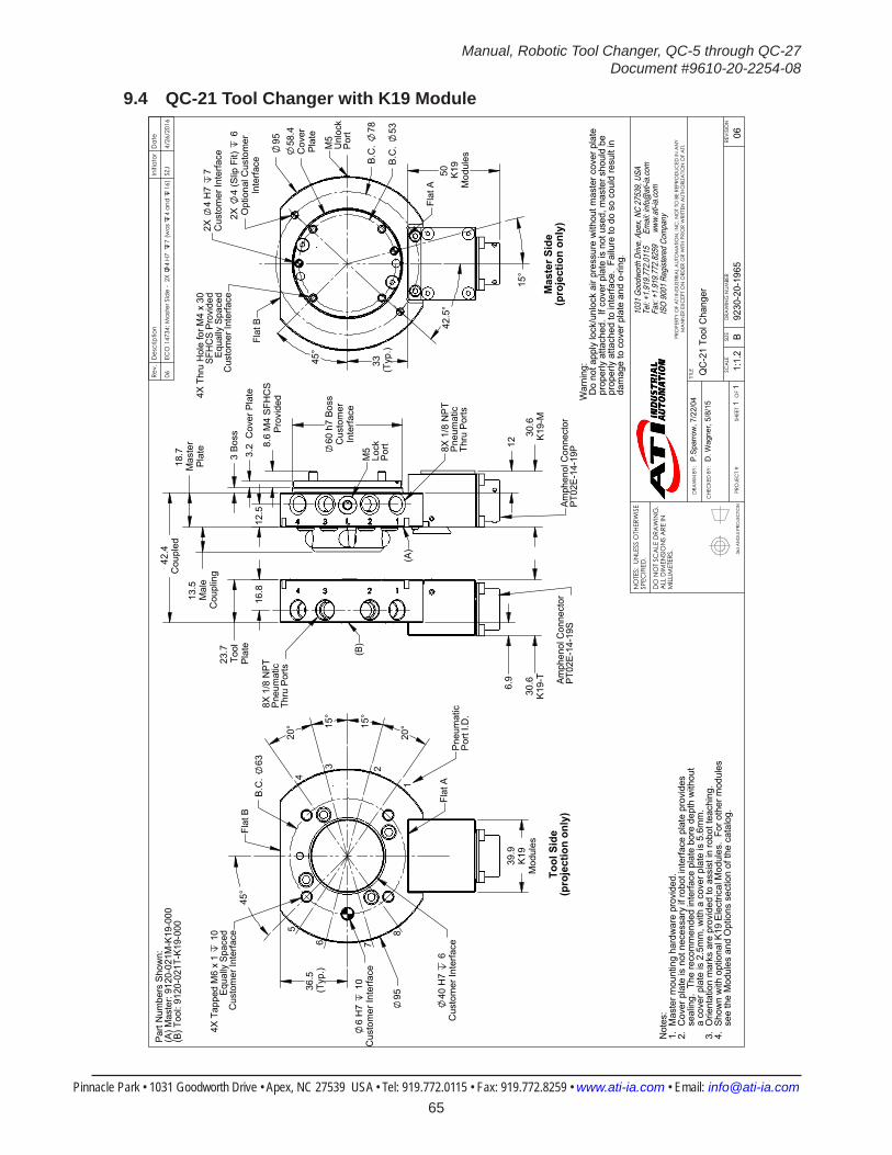
Manual, Robotic Tool Changer, QC-5 through QC-27Document #9610-20-2254-08
Pinnacle Park • 1031 Goodworth Drive • Apex, NC 27539 USA • Tel: 919.772.0115 • Fax: 919.772.8259 • www.ati-ia.com • Email: [email protected] 65
9.4 QC-21 Tool Changer with K19 Module
3rd
AN
GLE
PRO
JEC
TION
6 H
7 1
0C
usto
mer
Inte
rface
40 H
7 6
Cus
tom
er In
terfa
ce
95
36.5
(Typ
.)
39.9
K19
Mod
ules
B.C
. 63
15°
20°15
°
20°
45°
1
23
45
6 7
8
Flat
B
Flat
A
4X T
appe
d M
6 x
1 1
0Eq
ually
Spa
ced
Cus
tom
er In
terfa
ce
Tool
Sid
e(p
roje
ctio
n on
ly)
Pne
umat
icP
ort I
.D.
23.7
Tool
Pla
te
18.7
Mas
ter
Pla
te13
.5M
ale
Cou
plin
g
30.6
K19
-M
3 B
oss
Cou
pled
42.4
1260 h
7 B
oss
Cus
tom
erIn
terfa
ce
8.6
M4
SFH
CS
Pro
vide
d
3.2
Cov
er P
late
30.6
K19
-T
6.9
16.8
12.5
8X 1
/8 N
PTPn
eum
atic
Thru
Por
ts
M5
Lock
Port
(B)
(A)
Amph
enol
Con
nect
orPT
02E-
14-1
9PAm
phen
ol C
onne
ctor
PT02
E-14
-19S
8X 1
/8 N
PT
Pne
umat
icTh
ru P
orts
33 (Typ
.)
50 K19
Mod
ules
95 58.4
Cov
erP
late
2X
4 (S
lip F
it)
6O
ptio
nal C
usto
mer
Inte
rface
2X
4 H
7 7
Cus
tom
er In
terfa
ce B.C
. 53
15°
45°
B.C
. 78
42.
5°
Flat
B
4X T
hru
Hol
e fo
r M4
x 30
SFH
CS
Prov
ided
Equa
lly S
pace
dC
usto
mer
Inte
rface
M5
Unl
ock
Port
Flat
A
Mas
ter S
ide
(pro
ject
ion
only
)
Part
Num
bers
Sho
wn:
(A) M
aste
r: 91
20-0
21M
-K19
-000
(B) T
ool:
9120
-021
T-K1
9-00
0
Not
es:
1. M
aste
r mou
ntin
g ha
rdw
are
prov
ided
.2.
Cov
er p
late
is n
ot n
eces
sary
if ro
bot i
nter
face
pla
te p
rovi
des
s
ealin
g. T
he re
com
men
ded
inte
rface
pla
te b
ore
dept
h w
ithou
t
a c
over
pla
te is
2.5
mm
, with
a c
over
pla
te is
5.6
mm
.3.
Orie
ntat
ion
mar
ks a
re p
rovi
ded
to a
ssis
t in
robo
t tea
chin
g.4.
Sho
wn
with
opt
iona
l K19
Ele
ctric
al M
odul
es.
For o
ther
mod
ules
s
ee th
e M
odul
es a
nd O
ptio
ns s
ectio
n of
the
cata
log.
War
ning
: D
o no
t app
ly lo
ck/u
nloc
k ai
r pre
ssur
e w
ithou
t mas
ter c
over
pla
te p
rope
rly a
ttach
ed.
If co
ver p
late
is n
ot u
sed,
mas
ter s
houl
d be
p
rope
rly a
ttach
ed to
inte
rface
. Fa
ilure
to d
o so
cou
ld re
sult
in
dam
age
to c
over
pla
te a
nd o
-ring
.
Rev.
Des
crip
tion
Initi
ator
Dat
e
06EC
O 1
4734
; Mas
ter S
ide
- 2X
4
H7
7 (w
as
4 an
d
16)
SZJ
4/26
/201
6
B1:
1.2
11
REVI
SIO
N
NO
TES:
UN
LESS
OTH
ERW
ISE
SPEC
IFIE
D.
DO
NO
T SC
ALE
DRA
WIN
G.
ALL
DIM
ENSI
ON
S A
RE IN
M
ILLIM
ETER
S.
DRA
WN
BY:
CHE
CKE
D B
Y:
P.Sp
arro
w, 7
/22/
04
D. W
agne
r, 5/
8/15
TITLE SC
ALE
SIZE
DRA
WIN
G N
UMBE
R
PRO
JEC
T #
SHEE
T
O
F 92
30-2
0-19
65
06
PRO
PERT
Y O
F A
TI IN
DUS
TRIA
L A
UTO
MA
TION
, IN
C. N
OT
TO B
E RE
PRO
DUC
ED IN
AN
Y M
AN
NER
EXC
EPT
ON
ORD
ER O
R W
ITH P
RIO
R W
RITT
EN A
UTHO
RIZA
TION
OF
ATI.
1031
Goo
dwor
th Dr
ive, A
pex,
NC 27
539,
USA
Tel: +
1.919
.772.0
115
Em
ail: in
fo@ati
-ia.co
mFa
x: +1
.919.7
72.82
59
www
.ati-ia
.com
ISO
9001
Reg
ister
ed C
ompa
ny
QC
-21
Tool
Cha
nger
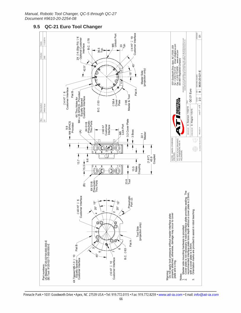
Manual, Robotic Tool Changer, QC-5 through QC-27Document #9610-20-2254-08
Pinnacle Park • 1031 Goodworth Drive • Apex, NC 27539 USA • Tel: 919.772.0115 • Fax: 919.772.8259 • www.ati-ia.com • Email: [email protected] 66
9.5 QC-21 Euro Tool Changer
3rd
AN
GLE
PRO
JEC
TION
60 h
7C
usto
mer
Inte
rface
13.5
Mal
eC
oupl
ing
22.1
Mas
ter
23.8
Tool
3 B
oss
3.2
Cov
er P
late
[1.8
1"]
45.9
Cou
pled
9.9
M4
SFH
CS
Pro
vide
d
9.6
1
5.3 1
3.7
8X G
1/8
Pneu
mat
icTh
ru P
orts
8X G
1/8
Pneu
mat
icTh
ru P
orts
M5
Lock
Por
t
(A)
(B)
6 H
7 1
0C
usto
mer
Inte
rface
40 H
7 6
Cus
tom
er In
terfa
ce
45°
B.C
. 63
20°
20°
15°
15°
4X T
appe
d M
6-1.
0 1
0Eq
ually
Spa
ced
Cus
tom
er In
terfa
ce
Tool
Sid
e(p
roje
ctio
n on
ly)
1
2345
6 7
8
Flat
A
Flat
B
Pne
umat
icP
ort I
.D.
36.5
Typ.
95M
aste
r & T
ool
45°
33 Typ.
4 H
7 8
Cus
tom
er In
terfa
ce
4 H
7 1
9C
usto
mer
Inte
rface
58.4
Cov
erP
late
42.
5°
2X
4 (S
lip F
it)
6O
ptio
nal C
usto
mer
Inte
rface
B.C
. 53
15°
B.C
. 78
Mas
ter S
ide
(pro
ject
ion
only
)
Flat
B
Flat
A
M5
Unl
ock
Por
t
4X T
hru
Hol
es fo
rM
4 x
35 S
FHC
S -
Pro
vide
dE
qual
ly S
pace
dC
usto
mer
Inte
rface
Not
es: M
aste
r sid
e m
ount
ing
hard
war
e is
pro
vide
d.1.
Cov
er p
late
is n
ot n
eces
sary
if ro
bot i
nter
face
pla
te p
rovi
des
seal
ing.
The
2.re
com
men
ded
inte
rface
pla
te b
ore
dept
h w
ithou
t a c
over
pla
te is
2.5
mm
,w
ith a
cov
er p
late
is 5
.6m
m.
Orie
ntat
ion
mar
ks a
re p
rovi
ded
to a
ssis
t in
robo
t tea
chin
g.3.P
art n
umbe
rs:
(A) M
aste
r: 91
20-0
21M
-000
-000
-E(B
) Too
l: 91
20-0
21T-
000-
000-
E
War
ning
:
Do
not a
pply
lock
pre
ssur
e w
ithou
t mas
ter i
nter
face
pla
te
prop
erly
atta
ched
; oth
erw
ise,
dam
age
may
occ
ur to
cov
er
plat
e an
d o-
ring.
Rev.
Des
crip
tion
Initi
ator
Dat
e
01In
itial
Issu
eD
SS11
/2/2
015
B2:
31
3RE
VISI
ON
NO
TES:
UN
LESS
OTH
ERW
ISE
SPEC
IFIE
D.
DO
NO
T SC
ALE
DRA
WIN
G.
ALL
DIM
ENSI
ON
S A
RE IN
M
ILLIM
ETER
S.
DRA
WN
BY:
CHE
CKE
D B
Y:
D. S
wan
son
11/0
2/15
D. W
agne
r 11/
5/15
TITLE SC
ALE
SIZE
DRA
WIN
G N
UMBE
R
PRO
JEC
T #
SHEE
T
O
F 96
30-2
0-02
1-E
01
PRO
PERT
Y O
F A
TI IN
DUS
TRIA
L A
UTO
MA
TION
, IN
C. N
OT
TO B
E RE
PRO
DUC
ED IN
AN
Y M
AN
NER
EXC
EPT
ON
ORD
ER O
R W
ITH P
RIO
R W
RITT
EN A
UTHO
RIZA
TION
OF
ATI.
1031
Goo
dwor
th Dr
ive, A
pex,
NC 27
539,
USA
Tel: +
1.919
.772.0
115
Em
ail: in
fo@ati
-ia.co
mFa
x: +1
.919.7
72.82
59
www
.ati-ia
.com
ISO
9001
Reg
ister
ed C
ompa
ny
QC
-21
Euro
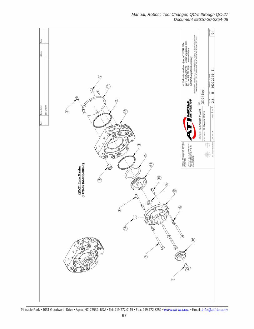
Manual, Robotic Tool Changer, QC-5 through QC-27Document #9610-20-2254-08
Pinnacle Park • 1031 Goodworth Drive • Apex, NC 27539 USA • Tel: 919.772.0115 • Fax: 919.772.8259 • www.ati-ia.com • Email: [email protected] 67
3rd
AN
GLE
PRO
JEC
TION
16
1
3
11
13
2
15
9
6
17
14
9
7
5
12
8
4
10QC
-21
Euro
Mas
ter
(912
0-02
1M-0
00-0
00-E
)
Rev.
Des
crip
tion
Initi
ator
Dat
e
-Se
e Sh
eet1
--
B2:
32
3RE
VISI
ON
NO
TES:
UN
LESS
OTH
ERW
ISE
SPEC
IFIE
D.
DO
NO
T SC
ALE
DRA
WIN
G.
ALL
DIM
ENSI
ON
S A
RE IN
M
ILLIM
ETER
S.
DRA
WN
BY:
CHE
CKE
D B
Y:
D. S
wan
son
11/0
2/15
D. W
agne
r 11/
5/15
TITLE SC
ALE
SIZE
DRA
WIN
G N
UMBE
R
PRO
JEC
T #
SHEE
T
O
F 96
30-2
0-02
1-E
01
PRO
PERT
Y O
F A
TI IN
DUS
TRIA
L A
UTO
MA
TION
, IN
C. N
OT
TO B
E RE
PRO
DUC
ED IN
AN
Y M
AN
NER
EXC
EPT
ON
ORD
ER O
R W
ITH P
RIO
R W
RITT
EN A
UTHO
RIZA
TION
OF
ATI.
1031
Goo
dwor
th Dr
ive, A
pex,
NC 27
539,
USA
Tel: +
1.919
.772.0
115
Em
ail: in
fo@ati
-ia.co
mFa
x: +1
.919.7
72.82
59
www
.ati-ia
.com
ISO
9001
Reg
ister
ed C
ompa
ny
QC
-21
Euro
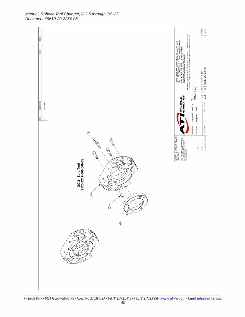
Manual, Robotic Tool Changer, QC-5 through QC-27Document #9610-20-2254-08
Pinnacle Park • 1031 Goodworth Drive • Apex, NC 27539 USA • Tel: 919.772.0115 • Fax: 919.772.8259 • www.ati-ia.com • Email: [email protected] 68
3rd
AN
GLE
PRO
JEC
TION
3
4
1
2
QC
-21
Euro
Too
l(9
120-
021T
-000
-000
-E)
Rev.
Des
crip
tion
Initi
ator
Dat
e
-Se
e Sh
eet1
--
B2:
33
3RE
VISI
ON
NO
TES:
UN
LESS
OTH
ERW
ISE
SPEC
IFIE
D.
DO
NO
T SC
ALE
DRA
WIN
G.
ALL
DIM
ENSI
ON
S A
RE IN
M
ILLIM
ETER
S.
DRA
WN
BY:
CHE
CKE
D B
Y:
D. S
wan
son
11/0
2/15
D. W
agne
r 11/
5/15
TITLE SC
ALE
SIZE
DRA
WIN
G N
UMBE
R
PRO
JEC
T #
SHEE
T
O
F 96
30-2
0-02
1-E
01
PRO
PERT
Y O
F A
TI IN
DUS
TRIA
L A
UTO
MA
TION
, IN
C. N
OT
TO B
E RE
PRO
DUC
ED IN
AN
Y M
AN
NER
EXC
EPT
ON
ORD
ER O
R W
ITH P
RIO
R W
RITT
EN A
UTHO
RIZA
TION
OF
ATI.
1031
Goo
dwor
th Dr
ive, A
pex,
NC 27
539,
USA
Tel: +
1.919
.772.0
115
Em
ail: in
fo@ati
-ia.co
mFa
x: +1
.919.7
72.82
59
www
.ati-ia
.com
ISO
9001
Reg
ister
ed C
ompa
ny
QC
-21
Euro
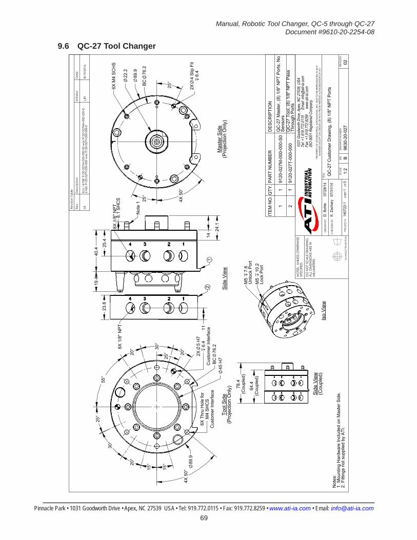
Manual, Robotic Tool Changer, QC-5 through QC-27Document #9610-20-2254-08
Pinnacle Park • 1031 Goodworth Drive • Apex, NC 27539 USA • Tel: 919.772.0115 • Fax: 919.772.8259 • www.ati-ia.com • Email: [email protected] 69
9.6 QC-27 Tool Changer
3rd
AN
GLE
PRO
JEC
TION
19.
4 4
0.4
24.
1
8.1
SH
CS
25.
4 14
8X 1
/8" N
PT
Not
e 1
1
23.
8
11
8X 1
/8" N
PT
2 B
C76
.2
4X
50°
25°
2X5
H7
6.4
Cus
tom
er In
terfa
ce6X
Thr
u H
ole
for
M4
SH
CS
Cus
tom
er In
terfa
ce
45
H7
89
.9
25°
30°
20°
15°
15°
55°
20°
30°
20°
BC
76.2
4X
50°
89
.9
25°
2X4
Slip
Fit
6.4
6X
M4
SC
HS
22
.2
25°
78.4
(Cou
pled
)
64.4
(Cou
pled
)
Sid
e V
iew
(Cou
pled
)Is
o V
iew
M5
10.2
Lock
Por
t
M5
7.6
Unl
ock
Por
t
Not
es:
Mou
ntin
g H
ardw
are
Incl
uded
on
Mas
ter S
ide.
1.Fi
tting
s no
t sup
plie
d by
ATI
.2.
Tool
Sid
e(P
roje
ctio
n O
nly)
Sid
e V
iew
Mas
ter S
ide
(Pro
ject
ion
Onl
y)
Revi
sion
Tabl
e
Rev.
Des
crip
tion
Initi
ator
Dat
e
03Ec
o 14
758;
912
0-02
7M-0
00-0
00-S
0 w
as 9
120-
027H
M-0
00-0
00-E
-61
60; 9
120-
027T
-000
-000
was
912
0-02
7T-0
00-0
00-E
LJH
8/19
/201
6
ITE
M N
O.Q
TY.P
AR
T N
UM
BE
RD
ES
CR
IPTI
ON
11
9120
-027
M-0
00-0
00-S
0Q
C-2
7 M
aste
r, (8
) 1/8
" NP
T P
orts
, No
Sen
sors
21
9120
-027
T-00
0-00
0Q
C-2
7 To
ol, (
8) 1
/8" N
PT
Pas
s Th
roug
h P
orts
B1:
21
3RE
VISI
ON
NO
TES:
UN
LESS
OTH
ERW
ISE
SPEC
IFIE
D.
DO
NO
T SC
ALE
DRA
WIN
G.
ALL
DIM
ENSI
ON
S A
RE IN
M
ILLIM
ETER
S.
DRA
WN
BY:
CHE
CKE
D B
Y:
D. B
ohle
07/
28/1
4
K. Z
acha
ry
07/3
1/14
TITLE SC
ALE
SIZE
DRA
WIN
G N
UMBE
R
PRO
JEC
T #
SHEE
T
O
F 96
30-2
0-02
714
0722
-102
PRO
PERT
Y O
F A
TI IN
DUS
TRIA
L A
UTO
MA
TION
, IN
C. N
OT
TO B
E RE
PRO
DUC
ED IN
AN
Y M
AN
NER
EXC
EPT
ON
ORD
ER O
R W
ITH P
RIO
R W
RITT
EN A
UTHO
RIZA
TION
OF
ATI.
1031
Goo
dwor
th Dr
ive, A
pex,
NC 27
539,
USA
Tel: +
1.919
.772.0
115
Em
ail: in
fo@ati
-ia.co
mFa
x: +1
.919.7
72.82
59
www
.ati-ia
.com
ISO
9001
Reg
ister
ed C
ompa
ny
QC
-27
Cus
tom
er D
raw
ing,
(8) 1
/8" N
PT P
orts
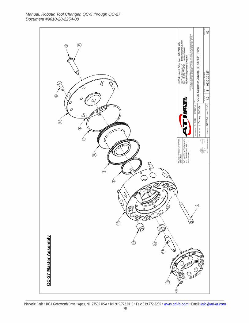
Manual, Robotic Tool Changer, QC-5 through QC-27Document #9610-20-2254-08
Pinnacle Park • 1031 Goodworth Drive • Apex, NC 27539 USA • Tel: 919.772.0115 • Fax: 919.772.8259 • www.ati-ia.com • Email: [email protected] 70
3rd
AN
GLE
PRO
JEC
TION
3
4
14
6
9 158
1
17
7
12
5
11
1318
16
QC
-27
Mas
ter A
ssem
bly
B1:
22
3RE
VISI
ON
NO
TES:
UN
LESS
OTH
ERW
ISE
SPEC
IFIE
D.
DO
NO
T SC
ALE
DRA
WIN
G.
ALL
DIM
ENSI
ON
S A
RE IN
M
ILLIM
ETER
S.
DRA
WN
BY:
CHE
CKE
D B
Y:
D. B
ohle
07/
28/1
4
K. Z
acha
ry
07/3
1/14
TITLE SC
ALE
SIZE
DRA
WIN
G N
UMBE
R
PRO
JEC
T #
SHEE
T
O
F 96
30-2
0-02
714
0722
-102
PRO
PERT
Y O
F A
TI IN
DUS
TRIA
L A
UTO
MA
TION
, IN
C. N
OT
TO B
E RE
PRO
DUC
ED IN
AN
Y M
AN
NER
EXC
EPT
ON
ORD
ER O
R W
ITH P
RIO
R W
RITT
EN A
UTHO
RIZA
TION
OF
ATI.
1031
Goo
dwor
th Dr
ive, A
pex,
NC 27
539,
USA
Tel: +
1.919
.772.0
115
Em
ail: in
fo@ati
-ia.co
mFa
x: +1
.919.7
72.82
59
www
.ati-ia
.com
ISO
9001
Reg
ister
ed C
ompa
ny
QC
-27
Cus
tom
er D
raw
ing,
(8) 1
/8" N
PT P
orts
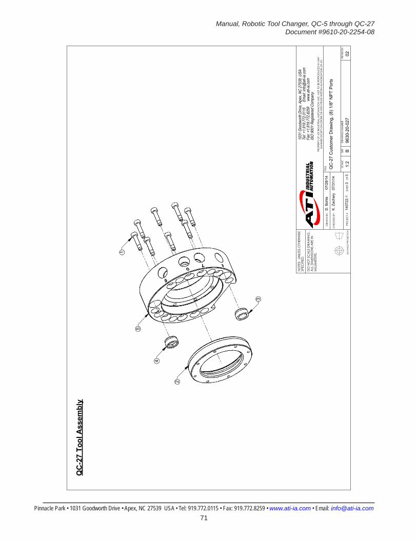
Manual, Robotic Tool Changer, QC-5 through QC-27Document #9610-20-2254-08
Pinnacle Park • 1031 Goodworth Drive • Apex, NC 27539 USA • Tel: 919.772.0115 • Fax: 919.772.8259 • www.ati-ia.com • Email: [email protected] 71
3rd
AN
GLE
PRO
JEC
TION
5
1
3
2
4
QC
-27
Tool
Ass
embl
y
B1:
23
3RE
VISI
ON
NO
TES:
UN
LESS
OTH
ERW
ISE
SPEC
IFIE
D.
DO
NO
T SC
ALE
DRA
WIN
G.
ALL
DIM
ENSI
ON
S A
RE IN
M
ILLIM
ETER
S.
DRA
WN
BY:
CHE
CKE
D B
Y:
D. B
ohle
07/
28/1
4
K. Z
acha
ry
07/3
1/14
TITLE SC
ALE
SIZE
DRA
WIN
G N
UMBE
R
PRO
JEC
T #
SHEE
T
O
F 96
30-2
0-02
714
0722
-102
PRO
PERT
Y O
F A
TI IN
DUS
TRIA
L A
UTO
MA
TION
, IN
C. N
OT
TO B
E RE
PRO
DUC
ED IN
AN
Y M
AN
NER
EXC
EPT
ON
ORD
ER O
R W
ITH P
RIO
R W
RITT
EN A
UTHO
RIZA
TION
OF
ATI.
1031
Goo
dwor
th Dr
ive, A
pex,
NC 27
539,
USA
Tel: +
1.919
.772.0
115
Em
ail: in
fo@ati
-ia.co
mFa
x: +1
.919.7
72.82
59
www
.ati-ia
.com
ISO
9001
Reg
ister
ed C
ompa
ny
QC
-27
Cus
tom
er D
raw
ing,
(8) 1
/8" N
PT P
orts

Manual, Robotic Tool Changer, QC-5 through QC-27Document #9610-20-2254-08
Pinnacle Park • 1031 Goodworth Drive • Apex, NC 27539 USA • Tel: 919.772.0115 • Fax: 919.772.8259 • www.ati-ia.com • Email: [email protected] 72
10. Terms and Conditions of SaleThe following Terms and Conditions are a supplement to and include a portion of ATI’s Standard Terms and Conditions, which are on file at ATI and available upon request.
ATI warrants to Purchaser that robotic Tool Changer products purchased hereunder will be free from defects in material and workmanship under normal use for a period of three (3) years from the date of shipment. This warranty does not cover components subject to wear and tear under normal usage or those requiring periodic replacement. ATI will have no liability under this warranty unless: (a) ATI is given written notice of the claimed defect and a Description thereof within thirty (30) days after Purchaser discovers the defect and in any event not later than the last day of the warranty period; and (b) the defective item is received by ATI not later ten (10) days after the last day of the warranty period. ATI’s entire liability and Purchaser’s sole remedy under this warranty is limited to repair or replacement, at ATI’s election, of the defective part or item or, at ATI’s election, refund of the price paid for the item. The foregoing warranty does not apply to any defect or failure resulting from improper installation, operation, maintenance or repair by anyone other than ATI.
ATI will in no event be liable for incidental, consequential or special damages of any kind, even if ATI has been advised of the possibility of such damages. ATI’s aggregate liability will in no event exceed the amount paid by purchaser for the item which is the subject of claim or dispute. ATI will have no liability of any kind for failure of any equipment or other items not supplied by ATI.
No action against ATI, regardless of form, arising out of or in any way connected with products or services supplied hereunder may be brought more than one (1) year after the cause of action accrued.
No representation or agreement varying or extending the warranty and limitation of remedy provisions contained herein is authorized by ATI, and may not be relied upon as having been authorized by ATI, unless in writing and signed by an executive officer of ATI.
Unless otherwise agreed in writing by ATI, all designs, drawings, data, inventions, software and other technology made or developed by ATI in the course of providing products and services hereunder, and all rights therein under any patent, copyright or other law protecting intellectual property, shall be and remain ATI’s property. The sale of products or services hereunder does not convey any express or implied license under any patent, copyright or other intellectual property right owned or controlled by ATI, whether relating to the products sold or any other matter except for the license expressly granted below.
In the course of supplying products and services hereunder, ATI may provide or disclose to Purchaser confidential and proprietary information of ATI relating to the design, operation or other aspects of ATI’s products. As between ATI and Purchaser, ownership of such information, including without limitation any computer software provided to Purchaser by ATI, shall remain in ATI and such information is licensed to Purchaser only for Purchaser’s use in operating the products supplied by ATI hereunder in Purchaser’s internal business operations.
Without ATI’s prior written permission, Purchaser will not use such information for any other purpose or provide or otherwise make such information available to any third party. Purchaser agrees to take all reasonable precautions to prevent any unauthorized use or disclosure of such information.
Purchaser will not be liable hereunder with respect to disclosure or use of information which: (a) is in the public domain when received from ATI; (b) is thereafter published or otherwise enters the public domain through no fault of Purchaser; (c) is in Purchaser’s possession prior to receipt from ATI; (d) is lawfully obtained by Purchaser from a third party entitled to disclose it; or (f) is required to be disclosed by judicial order or other governmental authority, provided that, with respect to such required disclosures, Purchaser gives ATI prior notice thereof and uses all legally available means to maintain the confidentiality of such information.