Embed Size (px)
Citation preview
DOE/EM-0532
Robotic TankInspection
End Effector
Tanks Focus Area
Prepared forU.S. Department of Energy
Office of Environmental ManagementOffice of Science and Technology
May 2000
Robotic TankInspection
End Effector
OST/TMS ID 278
Tanks Focus Area
Deployed atIdaho National Engineering and Environmental Laboratory
Idaho Falls, Idaho
iii
Purpose of this document
Innovative Technology Summary Reports are designed to provide potential users with theinformation they need to quickly determine whether a technology would apply to a particularenvironmental management problem. They are also designed for readers who mayrecommend that a technology be considered by prospective users.
Each report describes a technology, system, or process that has been developed and testedwith funding from DOE’s Office of Science and Technology (OST). A report presents the fullrange of problems that a technology, system, or process will address and its advantages to theDOE cleanup in terms of system performance, cost, and cleanup effectiveness. Most reportsinclude comparisons to baseline technologies as well as other competing technologies.Information about commercial availability and technology readiness for implementation is alsoincluded. Innovative Technology Summary Reports are intended to provide summaryinformation. References for more detailed information are provided in an appendix.
Efforts have been made to provide key data describing the performance, cost, and regulatoryacceptance of the technology. If this information was not available at the time of publication,the omission is noted.
All published Innovative Technology Summary Reports are available on the OST Web site athttp://ost.em.doe.gov/IFD/OSThome.htm under “Publications.”
iv
TABLE OF CONTENTS
1. SUMMARY page 1
2. TECHNOLOGY DESCRIPTION page 4
3. PERFORMANCE page 7
4. TECHNOLOGY APPLICABILITY AND ALTERNATIVES page 9
5. COST page 11
6. REGULATORY AND POLICY ISSUES page 13
7. LESSONS LEARNED page 15
APPENDICES
A. REFERENCES page 17
B. ACRONYMS AND ABBREVIATIONS page 19
1
SECTION 1SUMMARY
Technology Summary
Idaho National Engineering and Environmental Laboratory (INEEL) has 11 high-level liquid waste tanksat the Idaho Nuclear Technology and Engineering Center (INTEC). The tanks are single-shell, stainlesssteel tanks contained in concrete vaults. The concrete vaults around the tanks do not meet the necessaryrequirements for secondary containment, and therefore all of the tanks must be removed from service bythe end of 2012. Regulators are requiring that the containment capabilities of the tank structure beestablished before agreeing to closure proposals. The site is conducting tank integrity inspections togather information on current tank conditions and to establish loading limits for future remediation andclosure activities.
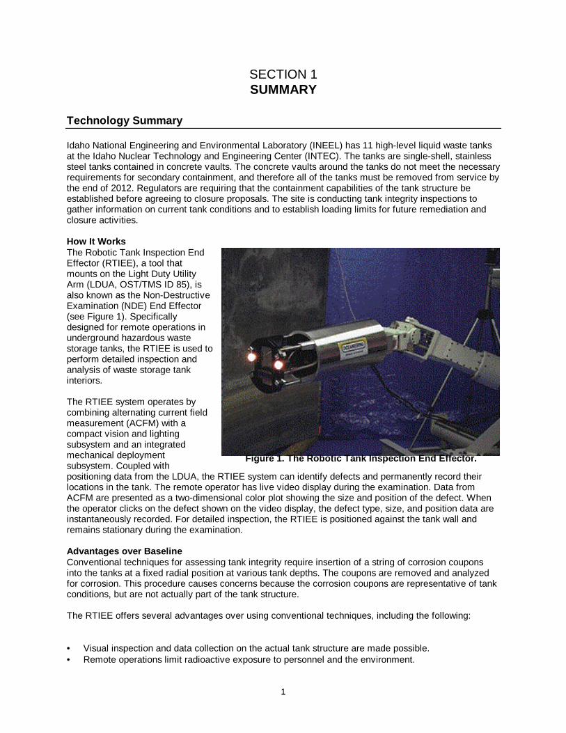
How It WorksThe Robotic Tank Inspection EndEffector (RTIEE), a tool thatmounts on the Light Duty UtilityArm (LDUA, OST/TMS ID 85), isalso known as the Non-DestructiveExamination (NDE) End Effector(see Figure 1). Specificallydesigned for remote operations inunderground hazardous wastestorage tanks, the RTIEE is used toperform detailed inspection andanalysis of waste storage tankinteriors.
The RTIEE system operates bycombining alternating current fieldmeasurement (ACFM) with acompact vision and lightingsubsystem and an integratedmechanical deploymentsubsystem. Coupled withpositioning data from the LDUA, the RTIEE system can identify defects and permanently record theirlocations in the tank. The remote operator has live video display during the examination. Data fromACFM are presented as a two-dimensional color plot showing the size and position of the defect. Whenthe operator clicks on the defect shown on the video display, the defect type, size, and position data areinstantaneously recorded. For detailed inspection, the RTIEE is positioned against the tank wall andremains stationary during the examination.
Advantages over Base lineConventional techniques for assessing tank integrity require insertion of a string of corrosion couponsinto the tanks at a fixed radial position at various tank depths. The coupons are removed and analyzedfor corrosion. This procedure causes concerns because the corrosion coupons are representative of tankconditions, but are not actually part of the tank structure.
The RTIEE offers several advantages over using conventional techniques, including the following:
• Visual inspection and data collection on the actual tank structure are made possible.• Remote operations limit radioactive exposure to personnel and the environment.
Figure 1. The Robotic Tank Inspection End Effector.
2
The following potential disadvantages may affect the selection of the RTIEE for use in tank wasteoperations:
• Specially trained personnel are required to operate the LDUA and the associated end effectors,including the RTIEE.
• A large amount of support equipment is necessary to perform operations, mostly associated with therequisite LDUA system, but also for the end effectors.
• The resolution of the system will show an existing problem, but it is not sufficient to identify small pitsthat could potentially evolve into a leak or other structural integrity problem.
Potential MarketsThis technology has the potential for use at other U.S. Department of Energy (DOE) sites for in-tankactivities. The RTIEE may also be used as is or with enhanced modifications for tanks of many differentsizes and types.
Demonstration Summary
The LDUA with the RTIEE was deployed at INTEC on February 12, 1999, to demonstrate itsperformance in a highly radioactive tank environment. Factory representatives from the vendor—Oceaneering Space Systems (OSS), Inc., of Houston, Texas—worked with INTEC staff during thedeployment.
Key ResultsThe RTIEE was deployed by the LDUA and performed numerous scans with minimal trouble. Because ofthe short period of time that OSS engineers were available to interpret data, the “fly-by” feature was nottested. The end effector was redeployed on February 24, 1999, and used to scan visible constructiondefects on the side of the tank. The end effector did not detect the defects, and the operators savedthree scans in an electronic file for later analysis by the OSS engineers. After analysis, the OSSengineers suggested that the end effector worked correctly, but the defects were too small to bedetected. Hence, further development may be necessary to improve the precision of the ACFMtechnique. In general, the inspection demonstrated that the structural integrity of the tank was very good.However, the RTIEE did not detect pits that were visually apparent, and tank integrity was evaluatedalmost exclusively based on the visual inspection.
ParticipantsThe following parties contributed to successful deployment of the RTIEE at INTEC:
• Tanks Focus Area (TFA)• Industry Programs• Characterization, Monitoring, and Sensor Technology Crosscutting Program• DOE Office of Science and Technology (OST)• DOE Office of Environmental Restoration (ER)• INEEL• Lockheed Martin Idaho Technologies Company• OSS
Commercial Availa bilityThe RTIEE was developed by OSS with funding from the OST under the direction of Industry Programsand TFA. The RTIEE is commercially available through OSS under the product name Robotic TankInspection End Effector. U.S. patent for the RTIEE is pending, but it is patented in the United Kingdomunder the number UK 990693.8. 2286678A, 2224575.
3
Future PlansUse of the LDUA and the RTIEE will continue at INTEC through fiscal year 2012 to sample and inspectup to 10 additional tanks.
Contacts
TechnicalPeter Gibbons, TFA Technology Integration Manager, Numatec Hanford Co., Richland, WA, (509) 372-
4926, [email protected] Thomas, Project Manager, INEEL, Idaho Falls, ID, (208) 526-3086, [email protected] Christensen, Cognizant Engineer, INEEL, Idaho Falls, ID, (208) 526-3653, [email protected] Beer, OSS, Houston, TX, (281) 228-5414, [email protected]
ManagementTed Pietrok, TFA Lead, DOE-Richland, Richland, WA, (509) 372-4546, [email protected] Gerdes, TFA Program Manager, DOE EM-50, Gaithersburg, MD, (301) 903-7289,
[email protected] Bedick, Industry Programs Lead, DOE-FETC, Morgantown, WV, (304) 285-4505,
OtherAll published Innovative Technology Summary Reports are available on the OST Web site athttp://ost.em.doe.gov/IFD/OSThome.htm under “Publications.” The Technology Management System(TMS), also available through the OST Web site, provides information about OST programs,technologies, and problems. The OST/TMS ID for the RTIEE is 278.
4
SECTION 2 TECHNOLOGY DESCRIPTION
Overall Process Definition
The LDUA and various end effectors are designed for work in hazardous waste underground storagetanks typified by those within the TFA purview. These tanks have limited access and contain anenvironment inhospitable to humans and most conventional tools. For further detail on the LDUA, seethe Innovative Technology Summary Report on Light Duty Utility Arm (DOE/EM-0406). The LDUA isimplicitly included as an essential piece of equipment used to deploy and enable operation of the RTIEE.
Goals and ObjectivesThe RTIEE is used to inspect underground hazardous waste storage tanks for indications of corrosion,cracks, pits, and weld defects prior to sampling of tank contents. The RTIEE can detect
• a wall thickness of up to 0.3125 inches with an accuracy of ±0.05 inches;• axial or transverse surface breaking cracks of 2.5 to 0.25 inches in length, ±0.125 inches, and
0.125 inches deep, ±0.05 inches; and• corrosion pitting with a minimum diameter of 0.125 inches and a depth of 0.0625 inches with a
measurement accuracy of ±0.025 inches.
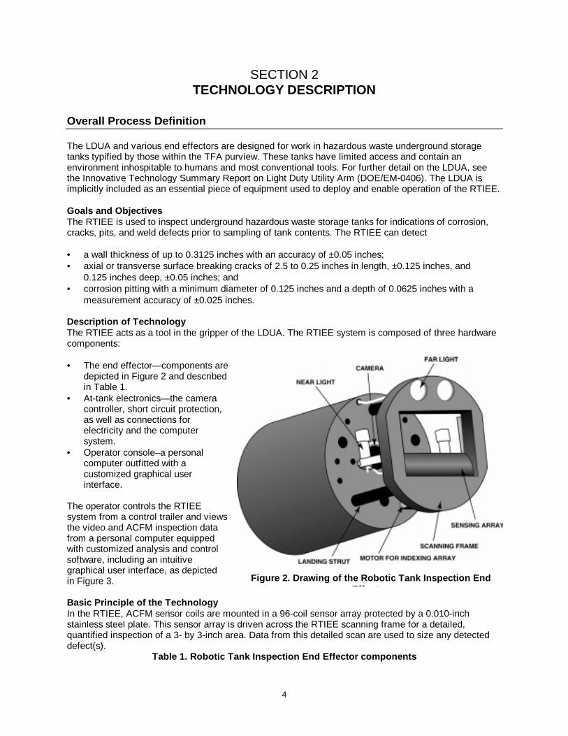
Descript ion of TechnologyThe RTIEE acts as a tool in the gripper of the LDUA. The RTIEE system is composed of three hardwarecomponents:
• The end effector—components aredepicted in Figure 2 and describedin Table 1.
• At-tank electronics—the cameracontroller, short circuit protection,as well as connections forelectricity and the computersystem.
• Operator console–a personalcomputer outfitted with acustomized graphical userinterface.
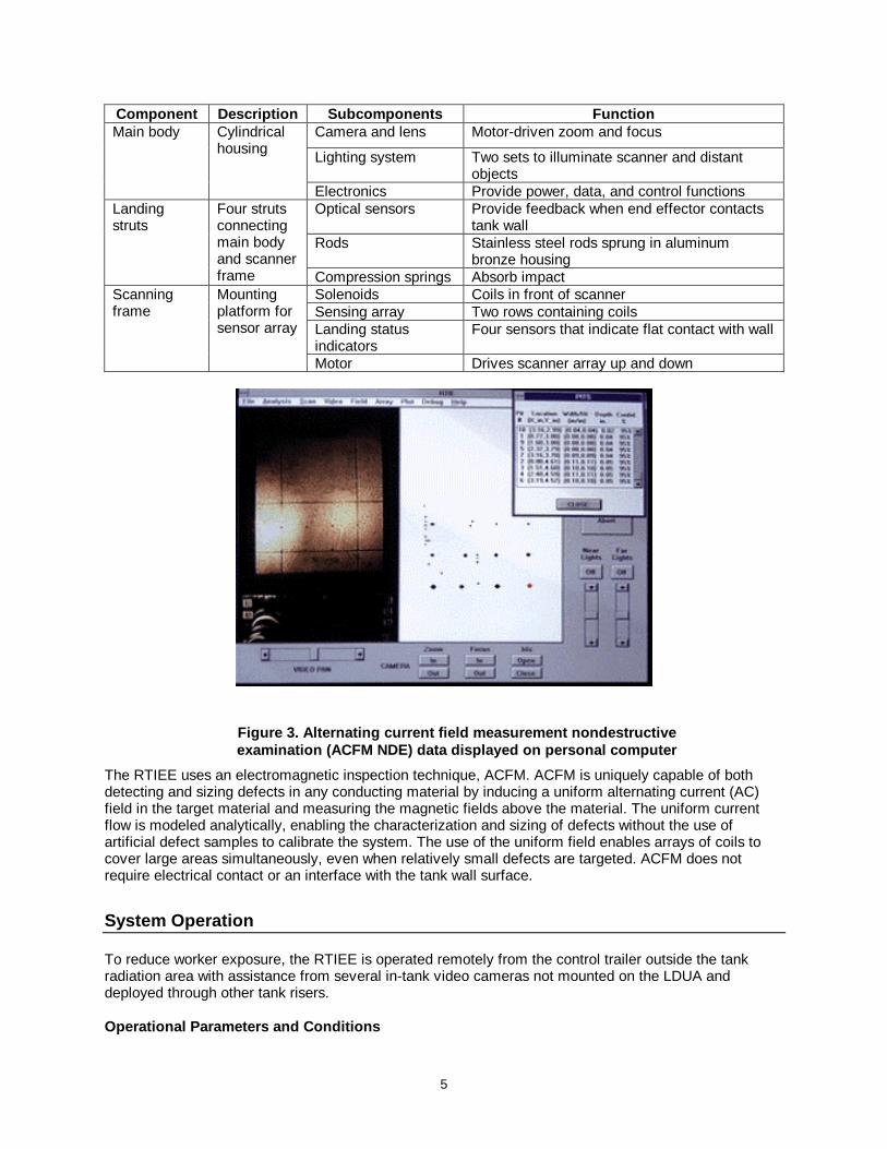
The operator controls the RTIEEsystem from a control trailer and viewsthe video and ACFM inspection datafrom a personal computer equippedwith customized analysis and controlsoftware, including an intuitivegraphical user interface, as depictedin Figure 3.
Basic Princ iple of the TechnologyIn the RTIEE, ACFM sensor coils are mounted in a 96-coil sensor array protected by a 0.010-inchstainless steel plate. This sensor array is driven across the RTIEE scanning frame for a detailed,quantified inspection of a 3- by 3-inch area. Data from this detailed scan are used to size any detecteddefect(s).
Table 1. Robotic Tank Inspection End Effector components
Figure 2. Drawing of the Robotic Tank Inspection EndEff t
5
Component Description Subcom ponents FunctionCamera and lens Motor-driven zoom and focus
Lighting system Two sets to illuminate scanner and distantobjects
Main body Cylindricalhousing
Electronics Provide power, data, and control functionsOptical sensors Provide feedback when end effector contacts
tank wallRods Stainless steel rods sprung in aluminum
bronze housing
Landingstruts
Four strutsconnectingmain bodyand scannerframe Compression springs Absorb impact
Solenoids Coils in front of scannerSensing array Two rows containing coilsLanding statusindicators
Four sensors that indicate flat contact with wall
Scanningframe
Mountingplatform forsensor array
Motor Drives scanner array up and down
The RTIEE uses an electromagnetic inspection technique, ACFM. ACFM is uniquely capable of bothdetecting and sizing defects in any conducting material by inducing a uniform alternating current (AC)field in the target material and measuring the magnetic fields above the material. The uniform currentflow is modeled analytically, enabling the characterization and sizing of defects without the use ofartificial defect samples to calibrate the system. The use of the uniform field enables arrays of coils tocover large areas simultaneously, even when relatively small defects are targeted. ACFM does notrequire electrical contact or an interface with the tank wall surface.
System Operation
To reduce worker exposure, the RTIEE is operated remotely from the control trailer outside the tankradiation area with assistance from several in-tank video cameras not mounted on the LDUA anddeployed through other tank risers.
Operat ional P arameters and C onditions
Figure 3. Alternating cu rrent field measurement nondestructiveexaminat ion (ACFM NDE) data displ ayed on personal computer
6
Operational constraints for the RTIEE center around the operating environment. The RTIEE is designedto withstand temperatures 0–50oC, and its radiation tolerance is 1 million rad. It requires neither cleansurfaces for inspection nor any contact with the surface being inspected. The RTIEE introduces no extraby-products in the inspection process. Also, it is slightly positively pressurized (less than 1 pound persquare inch) to perform inspections below liquid waste levels. Because the equipment is deployed insidean underground tank, severe weather is not a concern. If winds are high, the LDUA mast can be loweredfrom the vertical position to prevent damage to the system.
Materials and LaborThe RTIEE requires electricity to operate. Other expendable items consist of decontamination watergenerated during extraction of the LDUA. Decontamination water is left in the tank.
Two operators control the LDUA system from within the control center: one operates the LDUA while theother operates the installed end effector and the video displays and recorders. Two additional personnelperform end effector changes and decontaminate the LDUA and end effectors during removal from thetank.
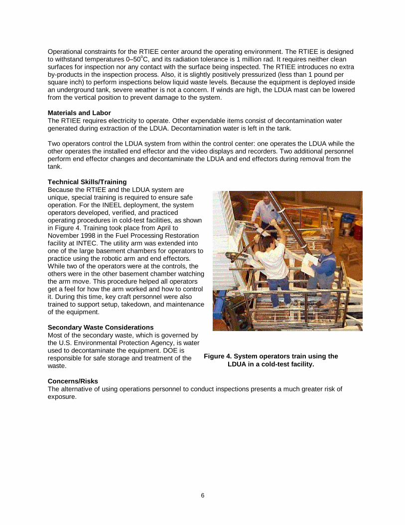
Technical Skills/TrainingBecause the RTIEE and the LDUA system areunique, special training is required to ensure safeoperation. For the INEEL deployment, the systemoperators developed, verified, and practicedoperating procedures in cold-test facilities, as shownin Figure 4. Training took place from April toNovember 1998 in the Fuel Processing Restorationfacility at INTEC. The utility arm was extended intoone of the large basement chambers for operators topractice using the robotic arm and end effectors.While two of the operators were at the controls, theothers were in the other basement chamber watchingthe arm move. This procedure helped all operatorsget a feel for how the arm worked and how to controlit. During this time, key craft personnel were alsotrained to support setup, takedown, and maintenanceof the equipment.
Secondary Waste Considerat ionsMost of the secondary waste, which is governed bythe U.S. Environmental Protection Agency, is waterused to decontaminate the equipment. DOE isresponsible for safe storage and treatment of thewaste.
Concerns/RisksThe alternative of using operations personnel to conduct inspections presents a much greater risk ofexposure.
Figure 4. System op erators train us ing theLDUA in a cold-test facility.
7
SECTION 3 PERFORMANCE
Demonstration Plan
Operation of the LDUA with the RTIEE was demonstrated in February 1997 at the Hanford Site anddeployed in February 1999 at INEEL. These tank installations successfully demonstrated surveillanceand inspection of both carbon and stainless steel tanks.
Major ObjectivesThe goal was to develop a single end effector that could perform electromagnetic and visual inspectionsimultaneously. Other success criteria were as follows:
• Camera and lighting enable unobstructed view of a distant tank wall and close-up view of a tank wallduring inspection.
• The scanning frame and strut are safely placed over the target area.• Scanning algorithms size corrosion pitting at a resolution not less than 0.3 inches wide by 0.3 inches
deep.• The graphical user interface concurrently displays real-time video and inspection.• All control functions successfully operate using the graphical interface.
The demonstration at Hanford focused on “fly-by” inspection mode. The system collected NDE data overa large area while the LDUA was in motion and determined whether there were any defects or corrosionissues. The deployment at INEEL was to inspect the walls of underground storage tanks from a fixedlocation for small surface-breaking defects, such as pits and cracks, as well as large defects that couldpermit a tank leak.
Major Elements and S upport EquipmentThe LDUA and RTIEE were deployed at INEEL in tank WM-188. A Stereo Viewing System was alsodeployed for a preliminary visual inspection inside the tank. Representatives of OSS assisted in pickingareas of interest for inspection and data interpretation. The LDUA was redeployed a few days later usinga sampling end effector to obtain heel samples.Support equipment for RTIEE deployment included the following:
• LDUA• at-tank instrument enclosure• power skid• containment skid• utility skid• control systems and trailer• end effector exchange system• decontamination system
The end effector is supported by software written by OSS, which can be used to catalog data andproduce a database on any given tank for future evaluation of detected flaws.
BoundariesPerformance of the LDUA and other end effectors is not discussed in this document.
8
Results
The RTIEE was developed to inspect underground hazardous waste storage tanks for cracks, pits, andwall defects. Since the RTIEE is dependent on the LDUA, the quantitative performance also representssuccessful performance of the LDUA. This section presents an overall discussion of the RTIEEperformance.
TestingThe RTIEE was demonstrated with the LDUA in the cold test facility at Hanford, Washington. OnFebruary 4, 1997, the system performed a fly-by NDE inspection on carbon steel sample plates mountedon a simulated tank wall surface. The system demonstrated the ability of a remote operator to locatedefect sites based on the combination of the visual feedback and the ACFM data as the end effector was“flown” over the plates. The operator used the ACFM data screens to identify suspected defects, whichwere seen as light-to-dark patterns in the real-time display. Suspected defect sites were recorded in atank wall map database along with the manipulator position, providing a graphical representation of theinspection flight path inside the tank along with markers at each of the suspected defect locationsobserved during the fly-by. The manipulator was then returned to the suspected defect sites for detailedinspections. Values for crack/pit length and depth returned by the RTIEE during the demonstrationverified the system’s ability to size a 1.5-inch crack within 0.060 inches or 10% (whichever is greater) ata fly-by rate of 1 inch/second.
DeploymentIn May 1998, the RTIEE was integrated with another LDUA at INEEL to ensure that both systems wouldbe operational. In August 1998, the RTIEE was scheduled for deployment in a tank containingradioactive liquid waste. When the scope of the project was modified to include submerging the endeffector in the waste, it was shipped to OSS for retrofitting to prevent leakage into its internal cavities. Insubsequent operation, the end effector maintained a constant negative pressure to prevent leakage andexplosion in the event of sparking.
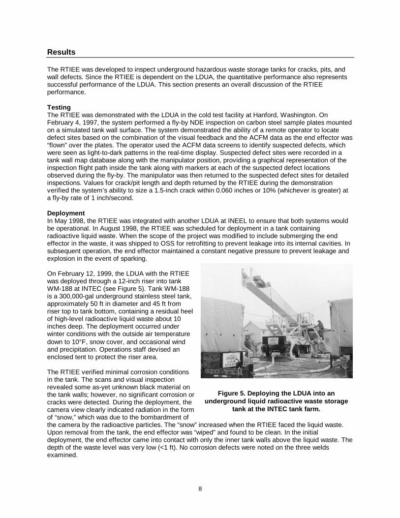
On February 12, 1999, the LDUA with the RTIEEwas deployed through a 12-inch riser into tankWM-188 at INTEC (see Figure 5). Tank WM-188is a 300,000-gal underground stainless steel tank,approximately 50 ft in diameter and 45 ft fromriser top to tank bottom, containing a residual heelof high-level radioactive liquid waste about 10inches deep. The deployment occurred underwinter conditions with the outside air temperaturedown to 10°F, snow cover, and occasional windand precipitation. Operations staff devised anenclosed tent to protect the riser area.
The RTIEE verified minimal corrosion conditionsin the tank. The scans and visual inspectionrevealed some as-yet unknown black material onthe tank walls; however, no significant corrosion orcracks were detected. During the deployment, thecamera view clearly indicated radiation in the formof “snow,” which was due to the bombardment ofthe camera by the radioactive particles. The “snow” increased when the RTIEE faced the liquid waste.Upon removal from the tank, the end effector was “wiped” and found to be clean. In the initialdeployment, the end effector came into contact with only the inner tank walls above the liquid waste. Thedepth of the waste level was very low (<1 ft). No corrosion defects were noted on the three weldsexamined.
Figure 5. Deploying the LDUA into anunderground liquid radioactive waste storage
tank at the INTEC tank farm.
9
SECTION 4 TECHNOLOGY APPLICABILITY AND ALTERNATIVES
Competing Technologies
The compact RTIEE combines tank video and lighting with ACFM electromagnetic inspection. TheRTIEE provides real-time detection and sizing of cracks and corrosion pitting in any conductive material.This combination is unlike other systems, which require separate deployments or calibrations tostandardize defects. Prior to development of the RTIEE using ACFM, eddy current, X-ray, or ultrasonictechniques were used.
The RTIEE using ACFM provides distinct advantages over alternative systems:
• ACFM is an electromagnetic NDE technique specifically developed to overcome the shortcomings ofeddy current techniques.
• ACFM is far less sensitive than eddy current to deviations in standoff distance and orientation.
• Unlike X-ray, ACFM is a benign electromagnetic technique that does not use a hazardous source anddoes not require interpretation of hard-to-read films.
• ACFM does not produce secondary waste like ultrasonics, which use transmission coupling fluid orgels to transmit sound energy into the target material.
• The NDE system does not require electrical contact with the surface, eliminating the need for surfacecleaning.
• The RTIEE system can work through most coatings, including paint, epoxy, rubber, grease, andsludge.
Technology Applicability
The RTIEE can be applied throughout the DOE complex in carbon steel and stainless steel tanks. TheRTIEE has many potential applications in preventive maintenance and inspection for repair work ofconductive materials. The system could be adapted to reside in a crawler or any other inspection vehicle.Inspection applications include pipelines, ship hulls, pressurized containment vessels, and other types ofstorage tanks. The system is radiation-hardened and electrically insulated to eliminate sparking inflammable or explosive tanks.
In determining the applicability of the technology for other tanks, parameters that should be consideredinclude the following:
• Access—Risers must be able to accommodate the equipment’s dimensions of 10.5 inches indiameter and 19.4 inches in length.
• In situ operations—Obstructions within the tank may hinder the equipment’s ability to access desiredlocations.
• Tank dome loading—Equipment may require support by a load-bearing platform.
10
• Anomaly size—for INEEL purposes, detection of minute cracks and pits requires higher resolutionthan what is offered by this technology.
Patents/Commercialization/Sponsor
A Federal Energy Technology Center (now National Energy Technology Laboratory) ResearchOpportunity Announcement (ROA) in March 1993 invited research proposals for development of thisnovel storage inspection technology. The ROA was awarded to Oceaneering Space Systems inSeptember 1993, with Technical Software Consultants (TSC) from the United Kingdom as thesubcontractor. TSC fabricated the printed circuit cards and assembled the tank-ready sensor array andassociated electronics.
Development of the RTIEE included efforts by the following:
• Pacific Northwest National Laboratory• INEEL• OSS• TFA• Industry Programs
During January 1997, OSS completed work on the tank-ready prototype and shipped the RTIEE systemto Hanford for the LDUA cold test. Pacific Northwest National Laboratory personnel performed themechanical integration with the LDUA and the testing. In November 1997, FETC issued a technicaldirection letter to complete the radiation-hardened RTIEE. It was delivered to INEEL in April 1998. TheHigh-Level Waste Program accepted ownership of the LDUA and RTIEE, and readiness reviews for itsdeployment were completed.
The RTIEE is commercially available through OSS under the product name Robotic Tank Inspection EndEffector. U.S. patent for the RTIEE is pending, but it is patented in the United Kingdom under thenumber UK 990693.8. 2286678A, 2224575.
11
SECTION 5 COST
Methodology
The methodology is to compare the benefit of deploying the RTIEE to that of using the baselinetechnology. The baseline technology is inspecting tanks by manually lowering corrosion coupons directlybelow the tank riser. The corrosion coupons are withdrawn periodically and analyzed for corrosion. Thecosts for deploying baseline technology are likely to be significantly less than for deploying the RTIEEbecause of the training and deployment costs associated with the LDUA. However, the RTIEE wasselected for deployment for the following reasons:
• It generates better tank inspection information. Corrosion coupons show corrosion rates but do notdetect and size existing surface defects.
• The LDUA was already being deployed for tank sampling.
• Technology for remote end effector exchange was available so that the Stereo Viewing System andthe RTIEE could be used without redeploying the LDUA.
When the cost of the overall project and the consequences of failure were considered, the RTIEE wasdetermined to have positive cost impacts, as discussed in the following sections.
Cost Analysis
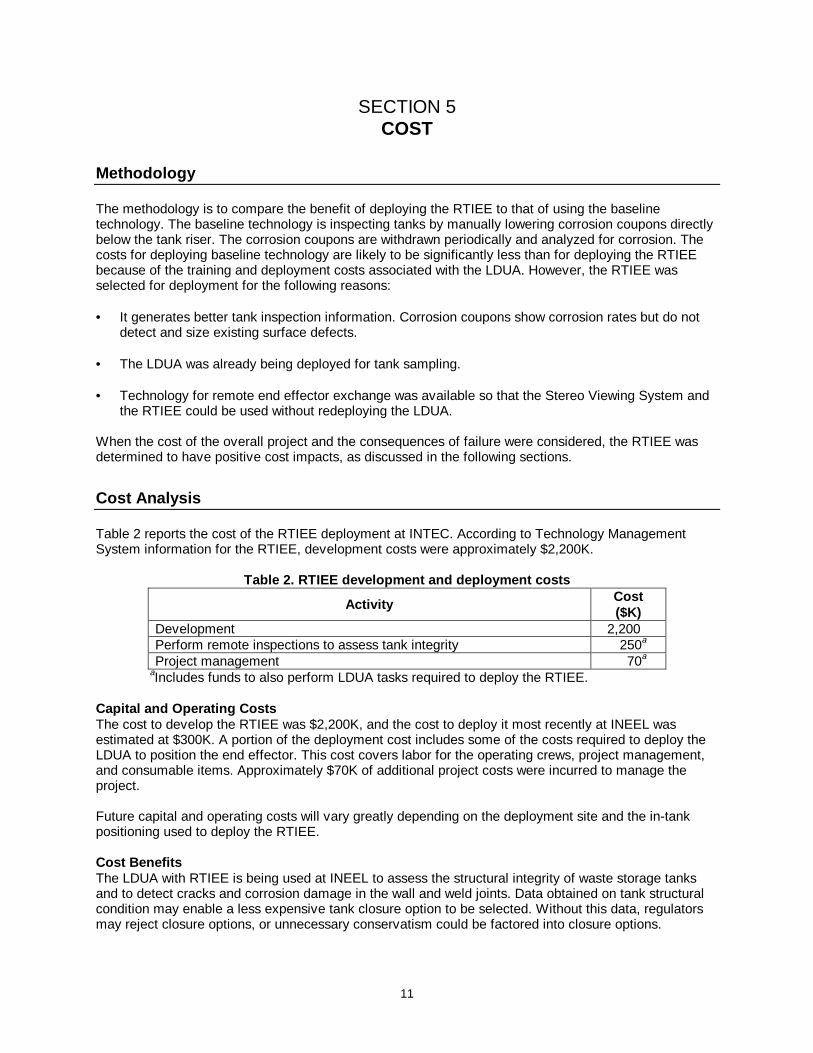
Table 2 reports the cost of the RTIEE deployment at INTEC. According to Technology ManagementSystem information for the RTIEE, development costs were approximately $2,200K.
Table 2. RTIEE development and deployment costs
ActivityCost($K)
Development 2,200Perform remote inspections to assess tank integrity 250a
Project management 70a
aIncludes funds to also perform LDUA tasks required to deploy the RTIEE.
Capital and Operat ing CostsThe cost to develop the RTIEE was $2,200K, and the cost to deploy it most recently at INEEL wasestimated at $300K. A portion of the deployment cost includes some of the costs required to deploy theLDUA to position the end effector. This cost covers labor for the operating crews, project management,and consumable items. Approximately $70K of additional project costs were incurred to manage theproject.
Future capital and operating costs will vary greatly depending on the deployment site and the in-tankpositioning used to deploy the RTIEE.
Cost BenefitsThe LDUA with RTIEE is being used at INEEL to assess the structural integrity of waste storage tanksand to detect cracks and corrosion damage in the wall and weld joints. Data obtained on tank structuralcondition may enable a less expensive tank closure option to be selected. Without this data, regulatorsmay reject closure options, or unnecessary conservatism could be factored into closure options.
12
Using the RTIEE results in cost benefits from
• performing inspections remotely rather than imposing risk to workers who manually inspect the insideof the tank,
• using collected data to implement less conservative retrieval and closure alternatives,• certifying existing tanks rather than constructing new ones, and• selecting better treatment options.
Table 3 summarizes estimated costs for the various closure options. The estimates address closing 11tanks, tank vaults, and ancillary piping located in the tank farm facility at INTEC. In the past, the baserequirement was clean closure (Option 2 or 3), which is to remove all waste, leave the tank structures inplace, and fill the tank voids. The current plan is to perform a risk-based clean closure, if possible, or alandfill closure, as a contingency, (Option 2 or 4), which includes removing the waste and grouting theremaining heel in place. Clean grout will then be used to fill the rest of the tank above the heel level andfill the surrounding vault. The cost differential between these options is over $50 million.
Table 3. Estimated costs of INEEL high-l evel waste tank closure opt ions
Closure optionEstimated cost
($ millions)1. Tank removal and demolition closure 5,3302. Risk-based clean closure, low-level waste grout
fill205
3. Risk-based clean closure, CERCLA waste fill 2384. RCRA landfill closure, low-level waste grout fill 1855. RCRA landfill closure, CERCLA waste fill 2206. Close to landfill standards, clean fill 135Source: Spaulding, et al. 1998.
Technology Scale-UpScale-up is not an issue with the RTIEE. However, inspection of large tanks may require multipledeployments of the LDUA if its reach is not sufficient to inspect suspicious areas.
Cost Conclusions
Using the RTIEE results in cost benefits because the data obtained on tank structural conditions mayenable a less expensive closure option to be selected. Furthermore, if the RTIEE reveals that tankstructural integrity is acceptable, tanks with little or no waste could be reused instead of building newtanks. The cost of a new tank is $67 million. INEEL will have a need for additional tanks to supportcease-use of the tank farm by 2012. Certification of one tank using this technology would fulfill this futureneed.
13
SECTION 6 REGULATORY AND POLICY ISSUES
Regulatory Considerations
The hazardous constituents of tank waste are subject to regulation under the Resource Conservation andRecovery Act (RCRA). Most states are authorized to implement RCRA, including permitting hazardouswaste treatment, storage, and disposal facilities.
Some of the tanks within the DOE complex were retired many years ago and contain legacy wastes.These tanks may be subject to remediation under the Comprehensive Environmental Response,Compensation, and Liability Act (CERCLA).
Waste storage and treatment facilities are also required to meet the Clean Air Act and Clean Water Actfor liquid and airborne effluents. Requirements are typically implemented at the state or even the locallevels for these statutes.
Treatment technologies are sometimes specified within compliance orders, such as Hanford’s FederalFacilities Agreement and Consent Order or the Idaho Settlement Agreement signed by DOE and thestate of Idaho. These agreements are often limited to immobilization technologies (waste forms) oremission control technologies. There are several examples where agreements and consent orders allowseparate decision processes to occur, such as evaluation of alternatives in an environmental impactstatement, through which a technical baseline is identified. Finally, engineering trade studies are used toselect a specific technology to meet the baseline. These trade studies are performed at a level far moredetailed than that typically addressed by regulatory authorities.
Secondary WasteMost of the secondary waste, which is governed by the U.S. Environmental Protection Agency, iswastewater derived from decontamination of the RTIEE equipment after each use. DOE is responsiblefor safe storage and treatment of the waste.
CERCLA EvaluationThis section summarizes how the RTIEE addresses the nine CERCLA evaluation criteria.
1. Overall Protection of Human Health and the Environment
• For tanks containing hazardous or radioactive components, inspecting and monitoring withremote-controlled operations significantly minimizes exposure to workers.
• Tanks can be isolated faster, with fewer personnel, and in much safer surroundings, thusreducing threats to human health and the environment.
2. Compliance with Applicable or Relevant and Appropriate Requirements (ARARs)
• The RTIEE with the LDUA was designed and deployed according to applicable regulatoryrequirements.
• Established procedures and controls are in place to ensure compliance.
3. Long-Term Effectiveness and Permanence
• This technology can help accelerate tank remediation and closure schedules.
14
• The RTIEE is radiation-hardened, with a radiation tolerance of 1 million rad.
• This technology was constructed to withstand temperatures of 0–50oC.
4. Reduction of Toxicity, Mobility, or Volume through Treatment
• Use of this system makes unnecessary the manual inspection and monitoring of tank integrity,which generate significant amounts of secondary waste due to exposure of additional tools andclothing to radiation sources.
5. Short-Term Effectiveness
Radiation exposure to workers is maintained as low as reasonably achievable (ALARA) through thefollowing measures:
• Inspection is controlled and data collected remotely from the tank.
• The RTIEE combines lights, camera, and positioning system, so fewer deployments into a tankto obtain necessary information are required.
• Established procedures and controls exist, and workers are thoroughly trained and qualified.
6. Implementability
• Efficiency and cost are optimized by deploying tools while the LDUA is in a tank for neededretrieval or closure activities.
• Worker exposure is minimized.
• Worker training and qualification programs and procedures are in place.
7. Cost data are provided in Section 5.
8. State (Support Agency) Acceptance
• Both the state of Idaho and EPA are parties of the federal facilities agreement that coversregulatory issues and establishes requirements for management of tanks.
9. Community Acceptance is discussed below.
Safety, Risks, Benefits, and Community Reaction
Because the main components of the RTIEE are operated remotely, there are no major worker safetyissues posed by using it. The support equipment includes a decontamination system as part of theLDUA. This feature allows for remote decontamination of the LDUA and the RTIEE. The other supportsystems are located above the tank and require hands-on operation, but the support equipment does notpresent any special safety concerns for workers.
Public and stakeholder reaction to the successful deployment of the LDUA and RTIEE in tank WM-188 atINTEC was positive. The technology is viewed as low risk and very promising, provided additionaldevelopment efforts can increase the resolution, in obtaining characterization data to appropriately closeunderground tanks as stipulated in the Idaho Settlement Agreement.
15
SECTION 7 LESSONS LEARNED
Implementation Considerations
Issues discovered at Hanford during the RTIEE demonstration resulted in the following suggestions forfuture deployments:
• Riser alignment was not performed with the optical alignment scope end effector due to flexibility ofthe vertical positioning mast and the fact the inner tube was not exactly concentric with the outertube. Instead, a simpler device was used successfully on the LDUA, which improved theperformance of the RTIEE.
• Standoff sensors were integrated into the end effector, providing more precise positional accuracythan LDUA sensors.
• Improvements to the graphic user interfaces and to the ergonomics of some of the components weresuggested and completed.
Deployment of the LDUA with the RTIEE at INTEC revealed the following insights that can be applied tofuture applications:
• Layout drawings of DOE underground storage tanks are typically reviewed to guide deployment ofthe LDUA and end effectors. Drawings are not always accurate. In the past, when new piping orchanges were made to a tank, documentation was not always updated to reflect the changes.Process knowledge can be used to help determine current configurations.
• The LDUA with end effectors, such as the RTIEE, has performed very reliably. Only minor problemshave been encountered when compared to other in-tank systems.
Technology Limitations and Needs for Future Development
The RTIEE can be a useful tool for the characterization of other tanks, including 10 other tanks atINTEC, or it can be used for inspections of pipelines and pressurized containment vehicles. However,consideration of the resolution required for each unique application is critical. At INTEC, the RTIEEperformed in accordance with specifications; however, in some instances the resolution was notadequate to satisfy inspection requirements for tank certification.
To assist with tank remediation and closure planning of INTEC tanks, INEEL required a technology withthe capability to inspect tank integrity beneath the tank heel. The RTIEE was modified during thesummer of 1998 to allow submersion to perform below-heel weld inspections on tank bottoms andknuckle regions. Other capabilities, such as cleaning submerged surfaces in preparation for inspection,may be necessary to perform submerged NDEs. The LDUA control systems will also need to beprogrammed with necessary algorithms and computer code. Testing should be performed usingsurrogate liquids, slurries, and sludge representative of INEEL and Hanford tank heels.
Further development may be necessary to improve the precision of the ACFM technique for usefulapplication in the INEEL Tank Farm.
17
APPENDIX A REFERENCES
Beer, R. 1999. Robotic Tank Inspection End Effector fact sheet. Houston, Tex.: Oceaneering Space
Systems.
Gasor T., B. Robertson, B. Lee, B. Wightman, M. M. Gittleman, and G. Hughes. 1997. Robotic TankInspection End Effector (RTIEE) for hazardous waste storage tanks. Houston, Tex.: OceaneeringSpace Systems.
Gittleman, M. M., B. Robertson, B. Lee, T. Gasor, G. Hughes. 1996. A fly-by robotic end effector forwaste storage tanks, in Proceedings of the ANS Topical Meeting on Nuclear and Hazardous WasteManagement. Seattle, Wash.: American Nuclear Society.
Hughes, G. and M. M. Gittleman 1995. A robotic end effector for inspection of storage tanks:Environmental technology development through industry partnership. Morgantown, W.V.:Morgantown Energy Technology Center.
Hughes, G., and M. M Gittleman. 1995. A robotic end effector for visual and electromagnetic inspectionof waste storage tank walls, pp. 347–54 in Proceedings of the ANS 6th Topical Meeting on Roboticsand Remote Systems. La Grange Park, Ill.: American Nuclear Society.
Idaho National Engineering and Environmental Laboratory. 1999. Inside of INEEL radioactive wastestorage tank examined with robotic arm. INEEL press release, Mar. 4.
Idaho National Engineering and Environmental Laboratory, Site Technology Coordination Group. 1999.High-Level Waste Program—Robotic arm examines inside of INEEL radioactive waste storage tank,in Solutions of the future technology and implementation spotlight.
Idaho National Engineering and Environmental Laboratory, Site Technology Coordination Group. 1999.LDUA—OSS Tank Inspection End Effector, in the INEEL EM technology catalog, posted on theSTCG home page at the URL http://techcatalog.inel.gov/searchreportresults.asp?id=106.
Patterson, M. 1999. LDUA deployment in tank WM-188. INEEL/EXT-99-01302. Idaho Falls, ID: Bechtel,Babcock&Wilcox Idaho.
Spaulding, B. C., R. A. Gavalya, M. M. Dahlmeir, L. C. Tuott, K. D. McAlister, K. G. DeCoria,S. P. Swanson, R. D. Adams, G. C. McCoy, and R. J. Turk. 1998. ICPP tank farm closure study.Volume 3: Cost estimates, planning schedules, yearly cost flowcharts, and life-cycle cost estimates,INEEL/EXT-97-01204-Vol. 3. Idaho Falls, Id.: Lockheed Idaho Martin Technologies Co.
U.S. Department of Energy, Federal Energy Technology Center. 1998. Robotic end effector forinspection of storage tanks fact sheet, at URLwww.fetc.doe.gov/publications/success/fetcss_robotic.html.
U.S. Department of Energy, Office of Science and Technology Development. 1998. Characterize INEELtank farm heels—LDUA deployment. Technology Task Plan, August.
Walsh J. 1998. LMITCO to use remotely controlled utility arm to examine interior of chem plant wastetanks. LMITCO Star. Idaho Falls, Id.: Idaho National Engineering and Environmental Laboratory,January.
19
APPENDIX BACRONYMS AND ABBREVIATIONS
ACFM alternating current field measurementALARA as low as reasonably achievableARARs applicable or relevant and appropriate requirementsCERCLA Comprehensive Environmental Response, Compensation, and Liability ActDOE U.S. Department of EnergyEPA Environmental Protection AgencyER (U.S. Department of Energy) Office of Environmental RestorationFETC Federal Energy Technology CenterINEEL Idaho National Environmental and Engineering LaboratoryINTEC Idaho Nuclear Technology Engineering CenterLDUA Light Duty Utility ArmNDE nondestructive examinationOSS Oceaneering Space SystemsOST Office of Science and TechnologyRCRA Resource Conservation and Recovery ActROA research opportunity announcementRTIEE Remote Tank Inspection End EffectorTFA Tanks Focus AreaTMS Technology Management SystemTSC Technical Software Consultants