Embed Size (px)
Citation preview
Robotic Lunar Exploration (RLE) Program
2008 Lunar Reconnaissance Orbiter (LRO) Payload
Proposal Information Package (PIP)
430-PROP-000001 Rev A
SIGNATURE ON FILE___________________
Prepared & Approved by: Craig Tooley LRO Project Manager SIGNATURE ON FILE___________________
Reviewed & Approved by: Tim Trenkle LRO Chief System Engineer SIGNATURE ON FILE___________________
Approved by: Jim Watzin RLE Program Manager
Goddard Space Flight Center
LRO Payload PIP 430-PROP-000001 Revision A
8/18/2004 Page 2 of 64
LUNAR RECONNAISSANCE ORBITER PROJECT
Payload Proposal Information Package for the LRO
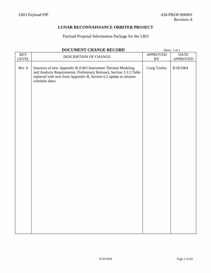
DOCUMENT CHANGE RECORD Sheet: 1 of 1 REV
LEVEL DESCRIPTION OF CHANGE APPROVED BY
DATE APPROVED
Rev A
Insertion of new Appendix B (LRO Instrument Thermal Modeling and Analysis Requirements, Preliminary Release), Section 3.3.3 Table replaced with new from Appendix B, Section 6.2 update to mission schedule dates
Craig Tooley
8/18/2004
LRO Payload PIP 430-PROP-000001 Revision A
8/18/2004 Page 3 of 64
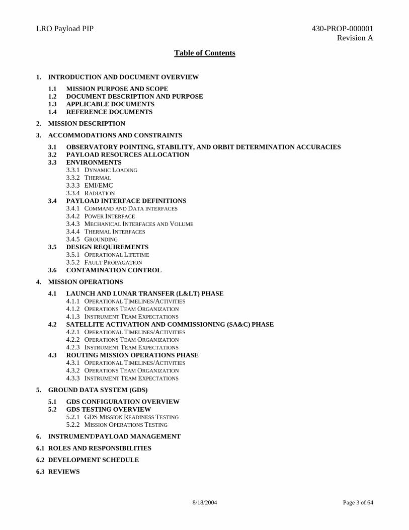
Table of Contents
1. INTRODUCTION AND DOCUMENT OVERVIEW 1.1 MISSION PURPOSE AND SCOPE 1.2 DOCUMENT DESCRIPTION AND PURPOSE 1.3 APPLICABLE DOCUMENTS 1.4 REFERENCE DOCUMENTS
2. MISSION DESCRIPTION 3. ACCOMMODATIONS AND CONSTRAINTS
3.1 OBSERVATORY POINTING, STABILITY, AND ORBIT DETERMINATION ACCURACIES 3.2 PAYLOAD RESOURCES ALLOCATION 3.3 ENVIRONMENTS
3.3.1 DYNAMIC LOADING 3.3.2 THERMAL 3.3.3 EMI/EMC 3.3.4 RADIATION
3.4 PAYLOAD INTERFACE DEFINITIONS 3.4.1 COMMAND AND DATA INTERFACES 3.4.2 POWER INTERFACE 3.4.3 MECHANICAL INTERFACES AND VOLUME 3.4.4 THERMAL INTERFACES 3.4.5 GROUNDING
3.5 DESIGN REQUIREMENTS 3.5.1 OPERATIONAL LIFETIME 3.5.2 FAULT PROPAGATION
3.6 CONTAMINATION CONTROL 4. MISSION OPERATIONS
4.1 LAUNCH AND LUNAR TRANSFER (L<) PHASE 4.1.1 OPERATIONAL TIMELINES/ACTIVITIES 4.1.2 OPERATIONS TEAM ORGANIZATION 4.1.3 INSTRUMENT TEAM EXPECTATIONS
4.2 SATELLITE ACTIVATION AND COMMISSIONING (SA&C) PHASE 4.2.1 OPERATIONAL TIMELINES/ACTIVITIES 4.2.2 OPERATIONS TEAM ORGANIZATION 4.2.3 INSTRUMENT TEAM EXPECTATIONS
4.3 ROUTING MISSION OPERATIONS PHASE 4.3.1 OPERATIONAL TIMELINES/ACTIVITIES 4.3.2 OPERATIONS TEAM ORGANIZATION 4.3.3 INSTRUMENT TEAM EXPECTATIONS
5. GROUND DATA SYSTEM (GDS) 5.1 GDS CONFIGURATION OVERVIEW 5.2 GDS TESTING OVERVIEW
5.2.1 GDS MISSION READINESS TESTING 5.2.2 MISSION OPERATIONS TESTING
6. INSTRUMENT/PAYLOAD MANAGEMENT 6.1 ROLES AND RESPONSIBILITIES 6.2 DEVELOPMENT SCHEDULE 6.3 REVIEWS
LRO Payload PIP 430-PROP-000001 Revision A
8/18/2004 Page 4 of 64
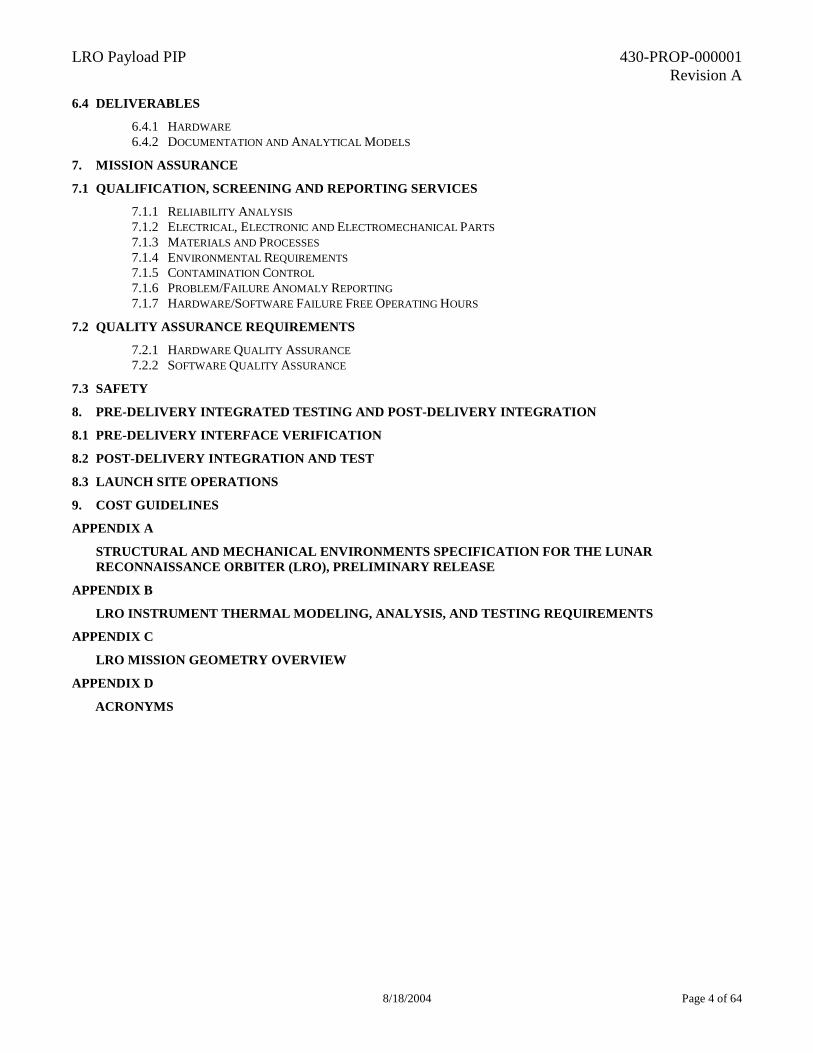
6.4 DELIVERABLES 6.4.1 HARDWARE 6.4.2 DOCUMENTATION AND ANALYTICAL MODELS
7. MISSION ASSURANCE 7.1 QUALIFICATION, SCREENING AND REPORTING SERVICES
7.1.1 RELIABILITY ANALYSIS 7.1.2 ELECTRICAL, ELECTRONIC AND ELECTROMECHANICAL PARTS 7.1.3 MATERIALS AND PROCESSES 7.1.4 ENVIRONMENTAL REQUIREMENTS 7.1.5 CONTAMINATION CONTROL 7.1.6 PROBLEM/FAILURE ANOMALY REPORTING 7.1.7 HARDWARE/SOFTWARE FAILURE FREE OPERATING HOURS
7.2 QUALITY ASSURANCE REQUIREMENTS 7.2.1 HARDWARE QUALITY ASSURANCE 7.2.2 SOFTWARE QUALITY ASSURANCE
7.3 SAFETY 8. PRE-DELIVERY INTEGRATED TESTING AND POST-DELIVERY INTEGRATION 8.1 PRE-DELIVERY INTERFACE VERIFICATION 8.2 POST-DELIVERY INTEGRATION AND TEST 8.3 LAUNCH SITE OPERATIONS 9. COST GUIDELINES APPENDIX A
STRUCTURAL AND MECHANICAL ENVIRONMENTS SPECIFICATION FOR THE LUNAR RECONNAISSANCE ORBITER (LRO), PRELIMINARY RELEASE
APPENDIX B LRO INSTRUMENT THERMAL MODELING, ANALYSIS, AND TESTING REQUIREMENTS
APPENDIX C LRO MISSION GEOMETRY OVERVIEW
APPENDIX D ACRONYMS
LRO Payload PIP 430-PROP-000001 Revision A
8/18/2004 Page 5 of 64
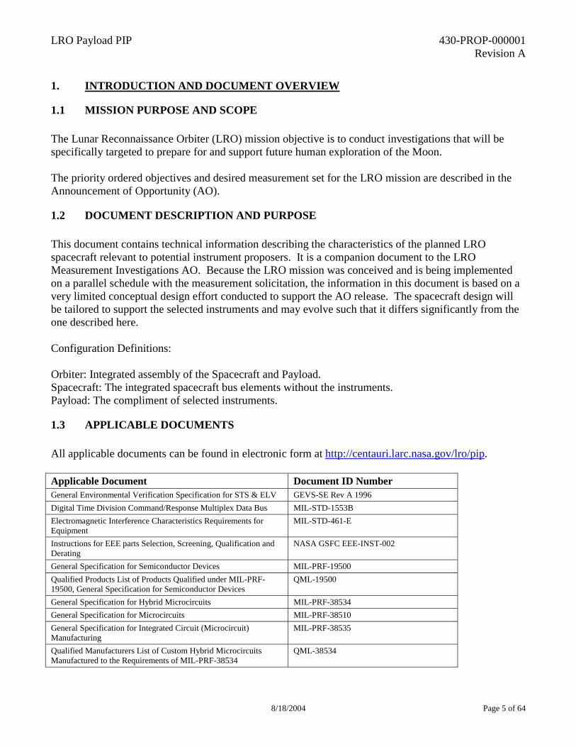
1. INTRODUCTION AND DOCUMENT OVERVIEW
1.1 MISSION PURPOSE AND SCOPE The Lunar Reconnaissance Orbiter (LRO) mission objective is to conduct investigations that will be specifically targeted to prepare for and support future human exploration of the Moon. The priority ordered objectives and desired measurement set for the LRO mission are described in the Announcement of Opportunity (AO).
1.2 DOCUMENT DESCRIPTION AND PURPOSE This document contains technical information describing the characteristics of the planned LRO spacecraft relevant to potential instrument proposers. It is a companion document to the LRO Measurement Investigations AO. Because the LRO mission was conceived and is being implemented on a parallel schedule with the measurement solicitation, the information in this document is based on a very limited conceptual design effort conducted to support the AO release. The spacecraft design will be tailored to support the selected instruments and may evolve such that it differs significantly from the one described here. Configuration Definitions: Orbiter: Integrated assembly of the Spacecraft and Payload. Spacecraft: The integrated spacecraft bus elements without the instruments. Payload: The compliment of selected instruments.
1.3 APPLICABLE DOCUMENTS All applicable documents can be found in electronic form at http://centauri.larc.nasa.gov/lro/pip. Applicable Document Document ID Number General Environmental Verification Specification for STS & ELV GEVS-SE Rev A 1996 Digital Time Division Command/Response Multiplex Data Bus MIL-STD-1553B Electromagnetic Interference Characteristics Requirements for Equipment
MIL-STD-461-E
Instructions for EEE parts Selection, Screening, Qualification and Derating
NASA GSFC EEE-INST-002
General Specification for Semiconductor Devices MIL-PRF-19500 Qualified Products List of Products Qualified under MIL-PRF-19500, General Specification for Semiconductor Devices
QML-19500
General Specification for Hybrid Microcircuits MIL-PRF-38534 General Specification for Microcircuits MIL-PRF-38510 General Specification for Integrated Circuit (Microcircuit) Manufacturing
MIL-PRF-38535
Qualified Manufacturers List of Custom Hybrid Microcircuits Manufactured to the Requirements of MIL-PRF-38534
QML-38534
LRO Payload PIP 430-PROP-000001 Revision A
8/18/2004 Page 6 of 64
Qualified Manufacturers List of Integrated Circuits (Microcircuits) Manufactured to the requirements of MIL-PRF-38535
QML-38535
Plastic Encapsulated Microcircuits (PEMs) Reliability/Usage Requirements
NASA GSFC PEM-INST-001
NASA Software Policies, NPD 2820.1 NASA NPD 2820.1
Lunar Reconnaissance Orbiter Measurement Set Investigations Announcement of Opportunity: http://centauri.larc.nasa.gov/lro/
NNH04ZSS003O
Structural Loads and Mechanical Environments Specification for the Lunar Reconnaissance Orbiter (LRO), Preliminary Release
Appendix A
LRO Instrument Thermal Modeling and Analysis Requirements, Preliminary Release
Appendix B
LRO Mission Geometry Overview Appendix C
1.4 REFERENCE DOCUMENTS Unless otherwise indicated all reference documents can be found in electronic form at http://centauri.larc.nasa.gov/lro/pip. Reference Document Document ID Number ORDT Website http://www.lpi.usra.edu/lunar_return/ N/A LRO Website http://lunar.gsfc.nasa.gov N/A Planetary Data System Website http://pds.jpl.nasa.gov/ N/A GSFC EEE Parts Policy GPG-XXXX (To be released June 2004) An Introduction to Space Radiation Effects on Microelectronics- L.D. Edmonds
JPL Pub 00-06 May 2000
SpaceWire SpaceWire Standard, ECSS-E-50-12A, January 24, 2003
The Radiation Environment for the James Webb Space Telescope, September 2000
N/A
GSFC Procedure & Guideline: Program and Project Management NASA GSFC GPG 7120.1B
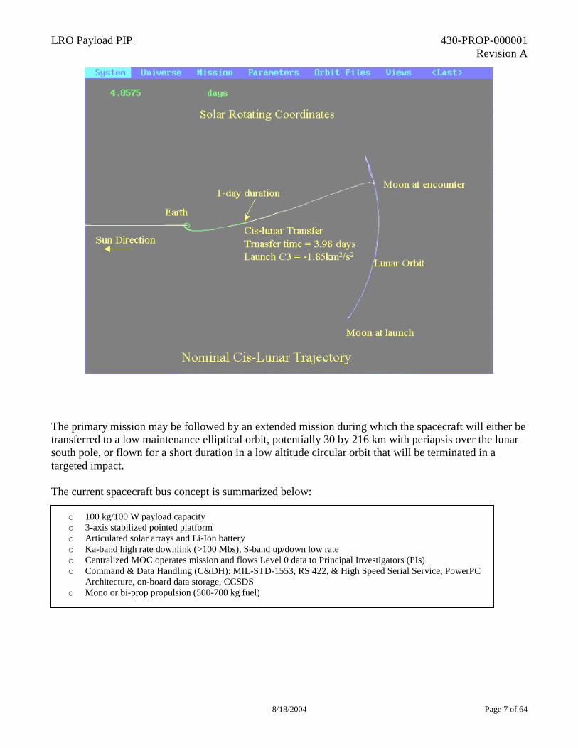
2. MISSION DESCRIPTION The mission will be launched from Kennedy Space Center (KSC) on a Delta II class Expendable Launch Vehicle (ELV) and then injected into a lunar trajectory by the ELV’s second or third stage. After a trans-lunar trajectory phase of approximately 100 hours, the spacecraft will be inserted into lunar orbit using the on-board propulsion system. The primary mission will be conducted in a circular polar mapping orbit with a nominal altitude of 50 km for one earth year. The 3-axis stabilized spacecraft will fly a nadir-pointing attitude with off-nadir maneuvers if necessary for and compatible with the entire instrument suite. The figure below illustrates the trajectory.
LRO Payload PIP 430-PROP-000001 Revision A
8/18/2004 Page 7 of 64
The primary mission may be followed by an extended mission during which the spacecraft will either be transferred to a low maintenance elliptical orbit, potentially 30 by 216 km with periapsis over the lunar south pole, or flown for a short duration in a low altitude circular orbit that will be terminated in a targeted impact. The current spacecraft bus concept is summarized below:
o 100 kg/100 W payload capacity o 3-axis stabilized pointed platform o Articulated solar arrays and Li-Ion battery o Ka-band high rate downlink (>100 Mbs), S-band up/down low rate o Centralized MOC operates mission and flows Level 0 data to Principal Investigators (PIs) o Command & Data Handling (C&DH): MIL-STD-1553, RS 422, & High Speed Serial Service, PowerPC
Architecture, on-board data storage, CCSDS o Mono or bi-prop propulsion (500-700 kg fuel)
LRO Payload PIP 430-PROP-000001 Revision A
8/18/2004 Page 8 of 64
3. ACCOMMODATIONS AND CONSTRAINTS
3.1 ORBITER POINTING, STABILITY, AND ORBIT DETERMINATION ACCURACIES An estimate of the spacecraft performance is summarized below. These estimates were developed based on typical Guidance, Navigation, and Control (GN&C) component capabilities and assumptions about potential instruments. The estimates do not include ephemeris errors or target location errors. The LRO design will be driven by the requirements and characteristics of the actual instruments selected and therefore these values should be regarded as estimates, not specifications. Proposal must include discussion of the impact of pointing and orbit determination accuracies on their proposed data product. Pointing Accuracy per axis (3σ) 60 arc-sec
Pointing Stability per axis (3σ) 5 arc-sec/axis over 1 ms 10 arc-sec/axis over 100 ms 20 arc-sec/axis over 4 sec.
Mapping Orbit Determination Accuracy
Mapping Orbit Determination Accuracy: 500/18 m (Total Position RMS/Radial RMS) 1-σ, assuming current lunar gravity model (LP100K) and existing RF tracking capabilities. With an improved gravity model of the Moon, accuracies of 150/10 m or better are possible.
An overview of the mission geometry in lunar orbit is given in Appendix C.
3.2 PAYLOAD RESOURCES ALLOCATION The allocation for the payload required to obtain the datasets has been established based on the preliminary mission design. Allocations for the individual instruments will be established after selection.
LRO Payload Resource Allocations
Mass 100 kg
Power
a. 100 Waverage b. Redundant switched operational and survival heater power
services (28V +/-6) at instrument interface to spacecraft. Data Volume Supported 900 Gb/day
LRO Payload PIP 430-PROP-000001 Revision A
8/18/2004 Page 9 of 64
Computational Resources
a. Instruments will handle all their own computing. However,
proposers may, for instruments with modest computational requirements, also identify significant cost or resource savings if spacecraft resources were used in place of instrument provided capability.
b. Transfer Rate to Mass Memory for Downlink: The
spacecraft will support real-time, simultaneous data transfers from the entire payload up to a total effective orbit average rate of 10 Mbps (up to 5 Mbps for an individual instrument if required). The peak allowed data rate (burst) may be higher.
Proposers are encouraged to consider the use of data compression techniques in order to minimize the burden on the spacecraft and allow the maximum possible data return from the payload.
3.3 ENVIRONMENTS The referenced or stated environmental information below will envelope the refined data that will become available during the design phase of the LRO mission.
3.3.1 Dynamic Loading Structural/mechanical loading environments are described in “Structural Loads and Mechanical Environments Specification for the Lunar Reconnaissance Orbiter (LRO),” which is Appendix A of this document.
3.3.2 Thermal The LRO spacecraft will utilize a passive thermal design to the maximum extent possible. The LRO spacecraft will provide a thermal sink for the instruments because of the hot environment on the nadir face of the LRO that will occur at and near the sub-solar point of the orbit. Therefore, the instruments shall isolate themselves from the exterior environment as much as possible, allowing only the instrument’s aperture to view the lunar environment. The operational mode and survival mode of the instruments may require operational and survival heaters that must be compatible with the LRO voltage range and allowable power values that are described in the Sections 3.2 and 3.4. The instrument thermal design must consider conditions of the variable orbital transient lunar thermal environment. The lunar environment shall be assumed to have a solar constant variation between 1420 W/m2 and 1280 W/m2, an albedo factor between 0.06 to 0.13, and a lunar surface emittance of 0.92. The following table is for reference only and shows the relative incident environment fluxes:
LRO Payload PIP 430-PROP-000001 Revision A
8/18/2004 Page 10 of 64
3.3.3 Electromagnetic Interference/Electromagnetic Contamination (EMI/EMC) The instrument level EMI/EMC requirements are as specified in MIL-STD-461-E.
3.3.4 Radiation Instruments must be designed to successfully collect the proposed data while operating in the lunar radiation environment. Both total radiation dose and Single Event Effects (SEE) must be considered. Total dose considerations shall have a minimum margin of a factor of 2. A characterization of the radiation environment for LRO has not yet been completed, but the reference “The Radiation Environment for the James Webb Space Telescope” can be used as an approximate guide in the interim. Information about radiation effects on electronics environment can also be found in the references in section 1.4.
3.4 PAYLOAD INTERFACE DEFINITIONS After selection, as part of the preliminary design process, Interface Control Documents (ICDs) will be developed between each instrument and the spacecraft bus. The information that follows describes the current conceptual design of the interfaces. These represent interfaces that are preferred, but not required. Proposers who wish to propose interfaces different from these must state the reasons and explain the impacts to their design if forced to conform to the preferred interfaces.
3.4.1 Command and Data Interfaces Instrument-to-spacecraft communication will be primarily supported on a MIL-STD1553B shared bus. If required, high-speed data can be communicated via a unique point-to-point serial interface.
solar + albedo lunar IR solar + albedo lunar IRlunar face 69 W/m^2 399 W/m^2 2 W/m^2 5 W/m^2zenith face 448 W/m^2 0 W/m^2 0 W/m^2 0 W/m^2right side 22 W/m^2 160 W/m^2 0 W/m^2 2 W/m^2left side 22 W/m^2 161 W/m^2 1423 W/m^2 2 W/m^2ram 285 W/m^2 161 W/m^2 1 W/m^2 2 W/m^2wake 285 W/m^2 158 W/m^2 1 W/m^2 2 W/m^2
Beta 0° (max. eclipse) Beta 90° (full sun)
LRO Payload PIP 430-PROP-000001 Revision A
8/18/2004 Page 11 of 64
The preferred instrument to spacecraft bus communication interfaces are listed in the table below:
Protocol/Interface Maximum Data Rate RS 422/UART 38.4 Kbps MIL-STD-1553B 50 Kbps RS 422/Clock & Data 5 Mbps High Speed Serial 5 Mbps orbit average/50 Mbps peak
(within payload 10 Mbps orbit average allocation) The spacecraft will provide a 1 Hz timing pulse for timing synchronization. The spacecraft will broadcast a coarse Mission Elapsed Time (MET) associated with the pulse.
3.4.2 Power Interface Instruments will be provided with switched redundant +28 V (+/-6) unregulated power lines. Instruments are required to operate between +21 V and +35 V and survive exposure to 0-40 V indefinitely without damage. Instruments will be unpowered during launch. A separate survival heater power service will be provided to each instrument by the spacecraft.
3.4.3 Mechanical Interfaces and Volume Instruments shall be attached using a redundant set of aerospace standard fasteners. The instruments will be aligned relative to the spacecraft coordinate system during integration with a minimum accuracy of 300 arc-sec per axis, 3σ, and knowledge of 30 arc-sec per axis, 3σ. If precision on-orbit alignments are required, they must be addressed in the instrument proposal. Instrument proposals should describe the instrument’s viewing requirements relative to the nadir direction as well as any unique requirements for off-nadir pointing or viewing. An estimate of the volume available for the payload and spacecraft (S/C) subsystems is shown in the figure and table below. Use of other Delta II configurations may result in additional available volume.
LRO Payload PIP 430-PROP-000001 Revision A
8/18/2004 Page 12 of 64
3.4.4 Thermal Interfaces The LRO spacecraft will provide a thermal sink for the instrument’s dissipated thermal power, but it is the instrument’s responsibility to minimize the environmental loading. The instruments must operate in all operational, safe mode and transfer orbit attitudes. Thermal Conductive Interface Since the spacecraft is providing a controlled sink, the instrument shall minimize its environmental loading such that the instrument conducts no more than +/-5 W of the supplied electrical power minus any power converted into active electromagnetic radiation for measurement data purposes. The conductive interface temperatures and fluxes shall be measured on the LRO spacecraft’s side of thermal interface.
VOLUMES
511 ft3
14.48 m3
REMAINING VOLUME INSTRUMENT & SPACECRAFT (TO BE
NEGOTIATED)
65 ft3
1.84 m3
LRO CORE PROPULSION MODULE VOLUME
576 ft3
16.32 m3
TOTAL VOLUME IN DELTA II FAIRING

LRO Payload PIP 430-PROP-000001 Revision A
8/18/2004 Page 13 of 64
Operational range of the structural/thermal spacecraft to instrument interface: -5 to +25°C Non-operating: -20 to +30°C Thermal Radiative Interface The instruments shall be Multi-Layer Insulation (MLI) blanketed in all locations where the instrument views the spacecraft internally. Instruments shall take into account any reflected and back-loaded energy from external solar arrays, antennas and spacecraft radiators if necessary. Control and Survival Heater Interface Heater circuits must be incorporated into the instrument design as required and are included in the allocation of power for the instrument suite. Instrument operational thermal control heaters shall be controlled by the instrument, and shall be thermally sized for the entire operational bus voltage range. The orbit average operational control heater, when added to the power draw for the rest of the instrument, shall not exceed the power requirement for the instrument. The peak power for the control heaters shall be included in the peak power number for the instrument. The survival heaters’ average power shall not exceed 25% of the orbital average operational power allocation per instrument.
3.4.5 Grounding The LRO spacecraft will be designed with a single point ground. Instrument primary and secondary returns must be isolated. Primary returns shall be tied to the spacecraft power system single point ground. Conductive exterior surfaces must be tied to chassis ground.
3.5 DESIGN REQUIREMENTS
3.5.1 Operational Lifetime In order to ensure a high probability of successfully completing the required characterization of the Moon, an instrument design lifetime of 2 years after launch has been established with a goal of 5 years to provide for the possibility of an extended mission. Specific guidance concerning selection of high reliability parts is contained in the Section 7 of this document.
3.5.2 Fault Propagation Instruments shall be designed such that no creditable fault within the instrument can propagate to the spacecraft bus or other instruments.
LRO Payload PIP 430-PROP-000001 Revision A
8/18/2004 Page 14 of 64
3.6 CONTAMINATION CONTROL Contamination control requirements will be defined after assessment of the selected instruments. Characterizations of an instrument’s contamination sensitivity and control requirements must be addressed in the proposal.
4. MISSION OPERATIONS This section discusses the anticipated mission operations concept for the LRO mission for each of the three main mission phases. Each mission phase description will include an overview of objectives, operational timelines & activities, operations team organization, and instrument team expectations. This concept is expected to evolve considerably over time, but the basis of the concept is derived from previous Goddard Space Flight Center (GSFC) Small Explorer (SMEX) operational approach. The major operational phases of the LRO mission are Launch and Lunar Transfer (L<), Satellite Activation and Commissioning (SA&C), and routine mission operations. Each phase requires a different level of support and expectations from the Principal Investigators (PIs)/Instrument Support Teams (ISTs). Besides supporting the various mission phases, it is expected that the PIs/ISTs will support various ground system and mission operations testing. Details on support expectations for pre-launch testing are outlined in Section 5.
4.1 LAUNCH AND LUNAR TRANSFER (L<) PHASE The primary objectives of the L< phase are to launch the satellite, inject the satellite into the lunar transfer orbit, and perform the lunar orbit injection maneuver. This phase occurs within the first week of the mission. During this phase, operations activities are focused on the following:
• Initial satellite system checkout • Lunar transfer trajectory monitoring & maintenance • Lunar orbit injection planning and execution • Primary satellite systems configuration • Ground system checkout and verification
4.1.1 Operational Timelines/Activities All available command uplink times are scheduled during this phase. All telemetry received is via the S-Band downlink. In addition to real-time telemetry, S-Band recorder dumps are performed during the ground contacts. The recorder dumps include recorded spacecraft and instrument housekeeping data that allow monitoring of satellite health when not in ground station view. The Mission Operations Team (MOT) coordinates and plans command activities based on ground station view periods. Before launch, an initial plan and activity sequence is developed that covers all scheduled activities and possible contingencies. Most of the operational activities in this phase involve the spacecraft and the instruments will be powered off.
LRO Payload PIP 430-PROP-000001 Revision A
8/18/2004 Page 15 of 64
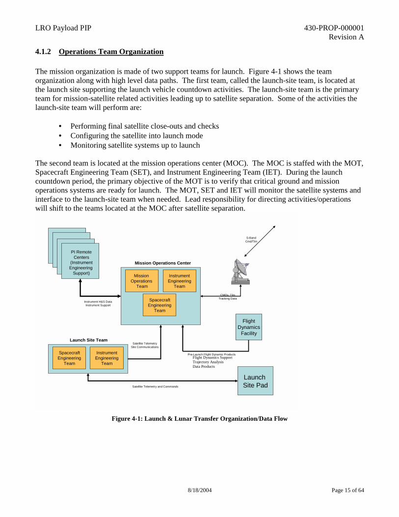
4.1.2 Operations Team Organization The mission organization is made of two support teams for launch. Figure 4-1 shows the team organization along with high level data paths. The first team, called the launch-site team, is located at the launch site supporting the launch vehicle countdown activities. The launch-site team is the primary team for mission-satellite related activities leading up to satellite separation. Some of the activities the launch-site team will perform are:
• Performing final satellite close-outs and checks • Configuring the satellite into launch mode • Monitoring satellite systems up to launch
The second team is located at the mission operations center (MOC). The MOC is staffed with the MOT, Spacecraft Engineering Team (SET), and Instrument Engineering Team (IET). During the launch countdown period, the primary objective of the MOT is to verify that critical ground and mission operations systems are ready for launch. The MOT, SET and IET will monitor the satellite systems and interface to the launch-site team when needed. Lead responsibility for directing activities/operations will shift to the teams located at the MOC after satellite separation.
Mission Operations Center
SpacecraftEngineering
Team
Mission Operations
Team
InstrumentEngineering
Team
S-BandCmd/Tlm
CMDs, TlmTracking Data
PI RemoteCenters
(InstrumentEngineering
Support)
Instrument H&S DataInstrument Support
Launch Site Team
SpacecraftEngineering
Team
InstrumentEngineering
Team
Satellite TelemetrySite Communications
Launch Site PadSatellite Telemetry and Commands
FlightDynamics
Facility
Pre-Launch Flight Dynamic Products
Figure 4-1: Launch & Lunar Transfer Organization/Data Flow
Flight Dynamics Support Trajectory Analysis Data Products
LRO Payload PIP 430-PROP-000001 Revision A
8/18/2004 Page 16 of 64
4.1.3 Instrument Team Expectations Representatives from each instrument are located at the MOC to support L< required activities. The representatives monitor instrument systems, participate in mission planning activities, and investigate any anomalous conditions relating to the instruments. Minimal support from the IET is expected since most activities will be focused on trajectory flight dynamics and initial spacecraft system checkout. Prior to launch the MOT provides training to the instrument support teams on the basic ground system functions and tools. This will allow the instrument teams to operate the MOC systems for monitoring instruments’ housekeeping data.
4.2 SATELLITE ACTIVATION AND COMMISSIONING (SA&C) PHASE The SA&C phase begins after Lunar Orbit Injection is complete. This phase will continue until all satellite activation and commissioning activities are complete. The primary objective of the SA&C phase is to configure the satellite for nominal mission operations mode. Activities include:
• Configuring remaining spacecraft systems • Perform spacecraft functional checkout and calibrations • Powering and configuring instruments • Performing initial functional checkout of instruments • Conducting any specialize calibration testing on the spacecraft and instruments
Priority during this phase is given to the spacecraft initialization and checkout activities followed by instrument activation and checkout.
4.2.1 Operational Timelines/Activities This phase is similar to the L< phase. All ground station contacts are scheduled in order to perform satellite activities. The spacecraft activation plan includes all spacecraft subsystem configuration and functional checkouts. Part of the plan will involve configuring the Ka-Band communication systems and other command and data components that are required for instrument activation The MOT develops an integrated activation and commissioning plan-using inputs from the spacecraft and instrument engineering teams. The plan lays out the necessary sequences in a logical manner in order to commission the satellite in the shortest amount of time. The plan is used for reference during daily planning meetings that coordinate the daily objectives and finalize detailed operation plans. While most of the instrument activities follow spacecraft bus checkout, some initial set of instrument related activities may occur earlier during spacecraft checkout.
LRO Payload PIP 430-PROP-000001 Revision A
8/18/2004 Page 17 of 64
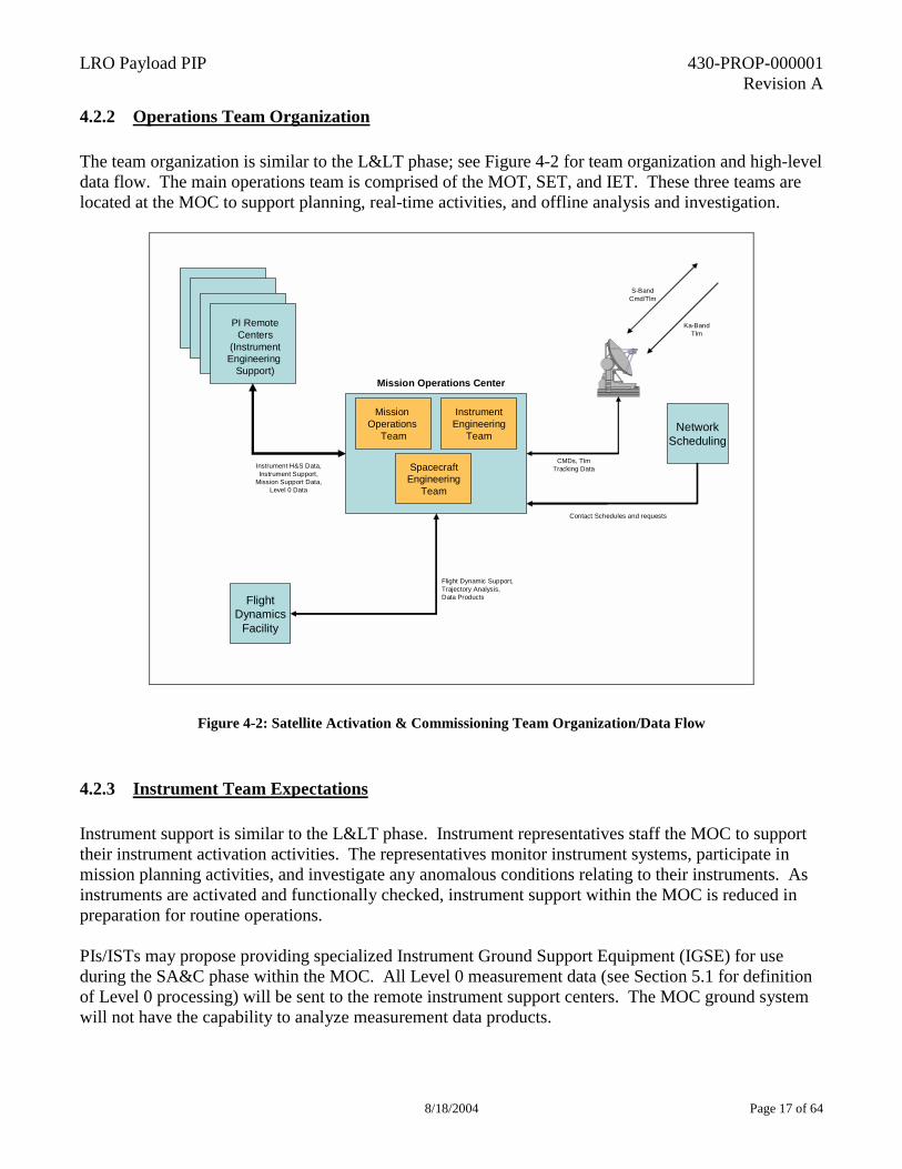
4.2.2 Operations Team Organization The team organization is similar to the L< phase; see Figure 4-2 for team organization and high-level data flow. The main operations team is comprised of the MOT, SET, and IET. These three teams are located at the MOC to support planning, real-time activities, and offline analysis and investigation.
Mission Operations Center
SpacecraftEngineering
Team
Mission Operations
Team
InstrumentEngineering
Team
S-BandCmd/Tlm
CMDs, TlmTracking Data
PI RemoteCenters
(InstrumentEngineering
Support)
Instrument H&S Data,Instrument Support,
Mission Support Data,Level 0 Data
Ka-BandTlm
FlightDynamics
Facility
Flight Dynamic Support,Trajectory Analysis, Data Products
NetworkScheduling
Contact Schedules and requests
Figure 4-2: Satellite Activation & Commissioning Team Organization/Data Flow
4.2.3 Instrument Team Expectations Instrument support is similar to the L< phase. Instrument representatives staff the MOC to support their instrument activation activities. The representatives monitor instrument systems, participate in mission planning activities, and investigate any anomalous conditions relating to their instruments. As instruments are activated and functionally checked, instrument support within the MOC is reduced in preparation for routine operations. PIs/ISTs may propose providing specialized Instrument Ground Support Equipment (IGSE) for use during the SA&C phase within the MOC. All Level 0 measurement data (see Section 5.1 for definition of Level 0 processing) will be sent to the remote instrument support centers. The MOC ground system will not have the capability to analyze measurement data products.
LRO Payload PIP 430-PROP-000001 Revision A
8/18/2004 Page 18 of 64
4.3 ROUTINE MISSION OPERATIONS PHASE Routine mission operations are expected to last throughout the first year of the mission and possibly continue during an extended mission. This phase begins once all SA&C objectives are complete. The MOC is staffed only with the MOT and other support required to the mission is through external interfaces.
4.3.1 Operational Timelines/Activities During routine operations, a minimum of one ground station contact per day is planned for uplink activities. If needed, additional ground contacts are scheduled for measurement data dumps. During each ground contact, the satellite engineering and housekeeping data is downlinked along with the instrument measurement data. The ground contact utilizes both the S-Band and Ka-Band links. During the command uplink contact, the MOT analyzes the real-time telemetry data, performs routine maintenance activities, performs data accountability analysis, and uplinks the daily command sequence. Daily Command Sequence Generation: PIs/ISTs will send updated instrument timelines on an as-needed basis to the MOT. Some instruments may not require routine command sequences while others require daily or weekly command sequences. Before delivery, the ISTs verify the timeline against the mission limits and constraints. The MOT generates the integrated command sequence and uplinks the load each day with the latest inputs. The integrated command load sequence generally contains commands for the following activities:
• Any instrument related commanding • Ground station view sequence • Data Dump commands • Routine satellite maintenance activities
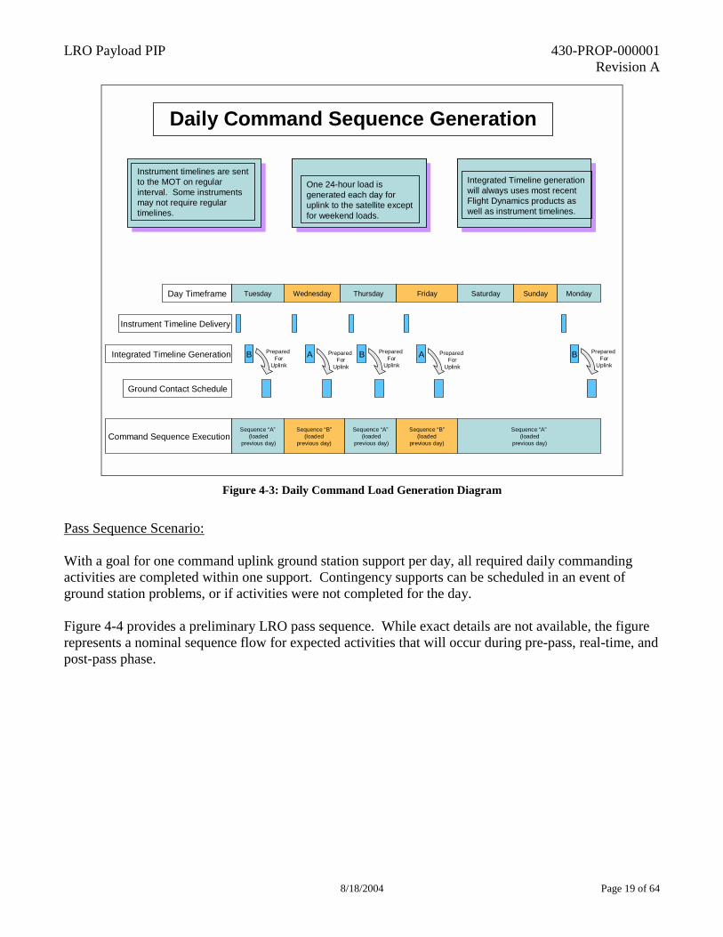
The command load sequence operates the satellite for the following day. This sequence is repeated throughout the mission Monday through Friday. On Friday, the PIs/ISTs deliver timelines that are valid for the next three days, covering Saturday through Monday. Figure 4-3 shows the preliminary daily command load generation concept.
LRO Payload PIP 430-PROP-000001 Revision A
8/18/2004 Page 19 of 64
Two 12-hour loads generated by noon EST.If unsuccessful, use backup timelines validated the previous day
ATS generation: Always uses most recent Flight Dynamics products. Wait for product generation on Monday, Wednesday, and Friday.
One 24-hour load is generated each day for uplink to the satellite except for weekend loads.
Instrument timelines are sent to the MOT on regular interval. Some instruments may not require regular timelines.
Integrated Timeline generation will always uses most recent Flight Dynamics products as well as instrument timelines.
Daily Command Sequence Generation
TuesdayDay Timeframe Wednesday
Instrument Timeline Delivery
Integrated Timeline Generation B A
Ground Contact Schedule
Command Sequence ExecutionSequence “A”
(loadedprevious day)
Sequence “B”(loaded
previous day)
Prepared For
Uplink
Prepared For
Uplink
Thursday Friday Saturday Sunday Monday
B Prepared For
Uplink
A Prepared For
Uplink
Sequence “A”(loaded
previous day)
Sequence “B”(loaded
previous day)
Sequence “A”(loaded
previous day)
B Prepared For
Uplink
Figure 4-3: Daily Command Load Generation Diagram
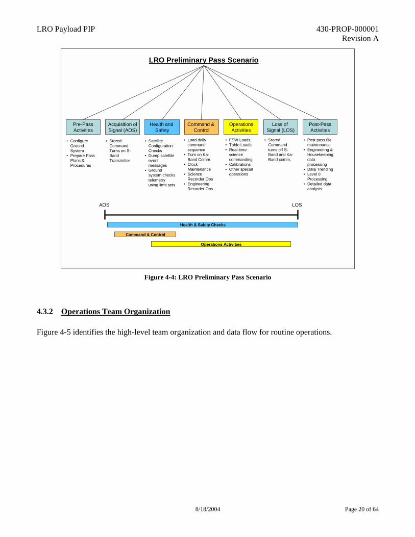
Pass Sequence Scenario: With a goal for one command uplink ground station support per day, all required daily commanding activities are completed within one support. Contingency supports can be scheduled in an event of ground station problems, or if activities were not completed for the day. Figure 4-4 provides a preliminary LRO pass sequence. While exact details are not available, the figure represents a nominal sequence flow for expected activities that will occur during pre-pass, real-time, and post-pass phase.
LRO Payload PIP 430-PROP-000001 Revision A
8/18/2004 Page 20 of 64
LRO Preliminary Pass Scenario
Pre-PassActivities
• Configure Ground System
• Prepare Pass Plans & Procedures
Acquisition ofSignal (AOS)
Health and Safety
Command & Control
OperationsActivities
Loss of Signal (LOS)
Post-PassActivities
• Stored Command Turns on S-Band Transmitter
• Satellite Configuration Checks
• Dump satellite event messages
• Ground system checks telemetry using limit sets
• Load daily command sequence
• Turn on Ka-Band Comm
• Clock Maintenance
• Science Recorder Ops
• Engineering Recorder Ops
• FSW Loads• Table Loads• Real-time
science commanding
• Calibrations• Other special
operations
• Stored Command turns off S-Band and Ka-Band comm,
• Post pass file maintenance
• Engineering & Housekeeping data processing
• Data Trending• Level 0
Processing• Detailed data
analysis
AOS LOS
Health & Safety Checks
Command & Control
Operations Activities
Figure 4-4: LRO Preliminary Pass Scenario
4.3.2 Operations Team Organization Figure 4-5 identifies the high-level team organization and data flow for routine operations.
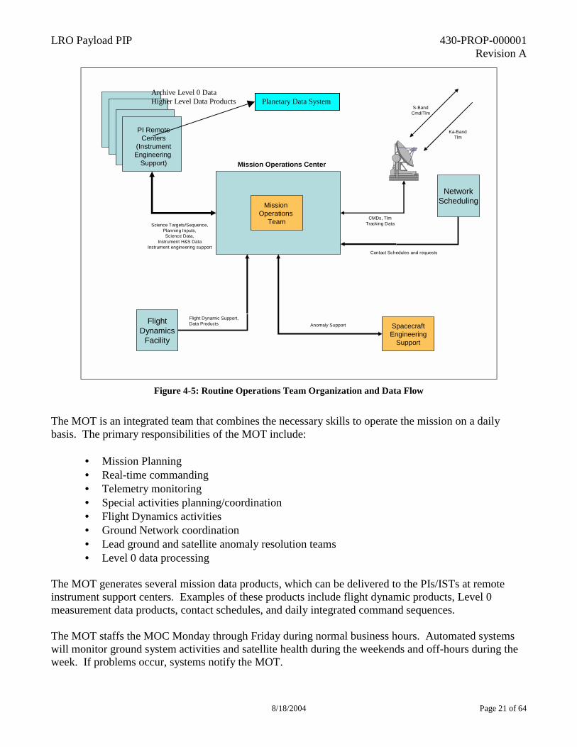
LRO Payload PIP 430-PROP-000001 Revision A
8/18/2004 Page 21 of 64
Mission Operations Center
SpacecraftEngineering
Support
S-BandCmd/Tlm
CMDs, TlmTracking Data
PI RemoteCenters
(InstrumentEngineering
Support)
Ka-BandTlm
Science Targets/Sequence,Planning Inputs,Science Data,
Instrument H&S DataInstrument engineering support
Mission Operations
Team
Anomaly SupportFlightDynamics
Facility
Flight Dynamic Support,Data Products
NetworkScheduling
Contact Schedules and requests
Figure 4-5: Routine Operations Team Organization and Data Flow
The MOT is an integrated team that combines the necessary skills to operate the mission on a daily basis. The primary responsibilities of the MOT include:
• Mission Planning • Real-time commanding • Telemetry monitoring • Special activities planning/coordination • Flight Dynamics activities • Ground Network coordination • Lead ground and satellite anomaly resolution teams • Level 0 data processing
The MOT generates several mission data products, which can be delivered to the PIs/ISTs at remote instrument support centers. Examples of these products include flight dynamic products, Level 0 measurement data products, contact schedules, and daily integrated command sequences. The MOT staffs the MOC Monday through Friday during normal business hours. Automated systems will monitor ground system activities and satellite health during the weekends and off-hours during the week. If problems occur, systems notify the MOT.
Archive Level 0 Data Higher Level Data Products Planetary Data System
LRO Payload PIP 430-PROP-000001 Revision A
8/18/2004 Page 22 of 64
The spacecraft engineering support team only supports the MOT when either an anomaly occurs which requires their support, or an update to the spacecraft flight software is required. The spacecraft engineering team is comprised mostly of the pre-launch development engineers. The ISTs will interface directly with the MOT for measurement data planning purposes. The ISTs are responsible for planning and developing daily command sequences for their instrument. The daily command sequences will be verified and checked against known limits and constraints. The ISTs are also responsible for maintaining the instrument flight software. If flight software updates are required, the ISTs will deliver the update that has been verified and checked. The MOT does not perform any additional verification or checking to instrument delivered files. The ISTs are responsible for monitoring their instrument systems and notifying the MOT if problems are discovered through instrument measurement data. Instrument health and status data is forwarded to the ISTs from the MOC after each ground contact. The MOC ground system monitors general instrument housekeeping data that is downlinked within the S-Band data streams. If the MOC ground system detects errors, the MOT notifies the appropriate instrument support center.
4.3.3 Instrument Team Expectations The PIs/ISTs will develop any required instrument command sequences. The instrument command sequences are verified against known constraints and limits before delivery to the MOT. The MOT uses these sequences to develop the satellite level sequence that is loaded every day between Monday and Friday. The integrated command sequence controls satellite activities for a 24-hr period except for weekend command sequences. The PIs/ISTs also provide engineering expertise when anomalous behavior occurs with their instrument. The MOT documents the anomaly but the PIs/ISTs perform the engineering analysis. PIs/ISTs are also responsible for maintaining and providing updates to instrument flight software on an as needed basis. The MOT maintains all instrument related flight procedures and command sequences. The PIs/ISTs direct and approve any necessary changes to the baseline set of flight procedures.
5. GROUND DATA SYSTEM This section discusses the configuration of the ground data systems (GDS) to be used in planning, simulation, uplink, downlink and product generation tasks described in Section 4.0. The section also provides details on pre-launch ground and mission operations testing that each instrument support centers or instrument engineering teams will participate in.
5.1 GDS CONFIGURATION OVERVIEW A functional representation of the ground data system is given in Figure 5-1 below. These software tools are used to support the MOT functions defined in section 4.0. A brief summary of major systems within the GDS is provided below.
LRO Payload PIP 430-PROP-000001 Revision A
8/18/2004 Page 23 of 64
• Real-time command & telemetry control system: System supports all real-time activities with the satellite that includes command, telemetry decommutation, data limit checking, and telemetry display capability. A goal for the LRO mission is to utilize the same command and control system for satellite integration and test.
• Trending System: System performs short term and long-term data trending on selected telemetry points. Short-term trend data is used to verify activities and analyze data for anomaly investigations. Long-term data is used by the MOT to detect long-term performance trends of various spacecraft systems.
• Flight Dynamic System: The flight dynamic system primary function is to generate required data products that are used on the LRO mission. The system ingests tracking data from the ground network to perform orbital analysis.
• Level 0 Processing: This system performs Level 0 measurement data processing. Level 0 functions include:
- Quality check and process packets to Level 0 - Perform time and/or sequence ordering - Annotate data quality and missing data - Remove overlap data (Redundant data) - Distribute processed quick-look and full measurement data sets to the remote
measurement data support centers
• Mission Planning System: The main function for this system is to generate the daily command load sequence. Other functions include generating necessary table loads and maintaining list of current operating tables and flight software loaded to the satellite.
• Automated Monitoring System: This system monitors the health and status of the satellite as well as the ground system during non-staffed hours for the MOT. If problems are detected, the system will notify the MOT until a response is received or the problem is corrected.
• Satellite Engineering Testbed: The main function of this system is to test any spacecraft flight software updates that are required post-launch. System will also be used by the MOT for training and test of new/modified procedures.
• Ground Network: The ground network performs scheduling, receives both S-Band and Ka-Band data, and transmits ground commands to the satellite. The ground network will temporary store all data for a short period while data transfers to the MOC are confirmed. The ground network will also provide flight dynamics tracking data necessary for new product generation.
• Flight Dynamics Facility: The main functions of the flight dynamics facility include planning support for maneuvers and trajectory analysis. This facility provides backup capability to the MOC flight dynamic system and can provide additional analysis/product support on an as-needed basis.
• Remote Principal Investigator (PI) Centers: The main function for the remote PI centers is to perform daily measurement data planning, data analysis and data distribution. A direct input into the mission planning system will allow the PI center to transfer daily planning sequences. Additional functions are listed below:
- Interface with MOT for mission planning and operations coordination - Provide detailed observation timeline sequence and special instrument command
inputs - Receive daily/weekly/monthly operations summary reports from the MOT
LRO Payload PIP 430-PROP-000001 Revision A
8/18/2004 Page 24 of 64
- Accept flight dynamics products from the flight dynamics system - Accept Level 0 data sets and further process measurement data - Long term measurement data archive - Provide on-call contingency operations support to the MOT - Deliver Level 0 data to Planetary Data System (PDS) for archiving - Perform data analysis and processing required to develop higher level data products - Deliver higher level data to PDS and NASA customers
• MOC Archiving System: Within the MOC Level 0 data will be archived as a backup to the data delivered to the PDS by the PIs.
Figure 5-1: GDS Functional Diagram
5.2 GDS TESTING OVERVIEW GDS testing includes both ground system mission readiness testing and planned mission operations testing. Instrument support teams as well as PIs/ISTs participate in some but not all planned tests. The following two sections highlight the testing that requires the participation of PIs/ISTs and instrument support centers.
LRO Payload PIP 430-PROP-000001 Revision A
8/18/2004 Page 25 of 64
5.2.1 GDS Mission Readiness Testing The GDS Mission Readiness Testing (MRT) is comprised of consolidated set of system tests, acceptance tests, and verification tests. System and acceptance tests involve testing functionality as well as all interfaces, including links to PI support centers. System and acceptance tests are performed following each major GDS build release. Based on the SMEX GDS implementation approach, there are typically between 2 to 4 major GDS build releases. The number of build releases will depend on amount of software re-use and new software development. A unified MRT plan is developed that maps MRT tests to mission requirements. Through a series of MRT tests, all ground related mission requirements are verified. Based on the SMEX GDS implementation approach, there are usually five MRT test series, but only two tests usually involve PIs/ISTs or instrument support centers. The following list identifies a preliminary MRT approach plan:
• MRT #1: Spacecraft Telemetry and Command Tests • MRT#2: MOC System Tests • MRT#3: Ground Network Tests • MRT#4: Measurement data processing and MOC to Instrument support center tests • MRT#5: Launch Site/End to End mission test
5.2.2 Mission Operations Testing Most GDS mission operations testing does not include/involve PIs/ISTs or instrument support centers. There are two types of operation tests that have been identified that will require participation from either PIs/ISTs and/or instrument support centers. The first test type is mission rehearsals. Mission rehearsals typically run over several days and simulate different phases of the mission. At least two rehearsals are expected to occur that will cover instrument activation and routine operations. For instrument activation rehearsal, the MOC is staffed using the actual mission teams (MOT, SET, and IET). All systems and interfaces are exercised according to the nominal activation sequence plan. The routine operations rehearsal simulates a nominal daily timeline. The rehearsal will include receiving products from the instrument support centers and performing measurement data processing. The second test type is operational readiness testing. These tests are short duration tests that are used to maintain operator and ground system proficiency during the last couple of months prior to launch. Tests include both segment level tests (focus on particular interface/systems) and end-to-end tests. Support is required from the instrument support centers and PIs/ISTs during some of these tests.
LRO Payload PIP 430-PROP-000001 Revision A
8/18/2004 Page 26 of 64
6. INSTRUMENT/PAYLOAD MANAGEMENT 6.1 ROLES AND RESPONSIBILITIES Top-level LRO mission roles and responsibilities are described below: RLE Program Manager: The RLE Program manager is responsible for the overall RLE program, of which LRO is the first mission, and is supported by a small staff that includes program level systems engineers as well as business and administrative support. LRO Project Manager: The LRO Project Manager is responsible for the overall success of the LRO mission and directly manages the design and construction of the LRO spacecraft bus as well as providing the technical, schedule and financial monitoring of the instrument contracts. LRO Chief Systems Engineer: The LRO Chief Systems engineer is responsible for the end-to-end systems engineering for the LRO mission and is the most senior technical authority on the project. The Chief System Engineer develops and maintains the spacecraft bus technical requirements and the ICDs with the instruments. The Chief Engineer chairs or co-chairs all mission technical peer reviews. LRO Instrument Systems Manager: The Instrument Systems Manager provides systems engineering for the integrated payload and monitors the technical progress of the instrument development. Principal Investigators (PIs): PIs are responsible for all aspects of successful completion of the proposed measurement data set generation. This includes the instrument design and development, fabrication, test and calibration, and delivery of flight hardware, software, documentation, and associated support equipment within project schedule and allocated resources. The PIs are also responsible for planning and supporting instrument operation, data analysis and reduction, and delivery of higher-level data products to the NASA customers and the PDS. PIs will participate in the LRO Investigators Team meetings and associated working groups.
6.2 DEVELOPMENT SCHEDULE An overview of the mission schedule is shown below:
�
�
�
�
�
2004 2005 2006 2007 20084/6 FBO
6/18AO Release
11/15AO Select
5/15 PDR 10/15Confirm
4/15 CDR 10/15InstrumentDelivery
10/15 LRD
7/7 Pre-Prop Conf.
2004 2005 2006 2007 20084/6 FBO
6/18AO Release
11/15AO Select
5/15 PDR 10/15Confirm
4/15 CDR 10/15InstrumentDelivery
10/15 LRD
7/7 Pre-Prop Conf.
LRO Payload PIP 430-PROP-000001 Revision A
8/18/2004 Page 27 of 64
�
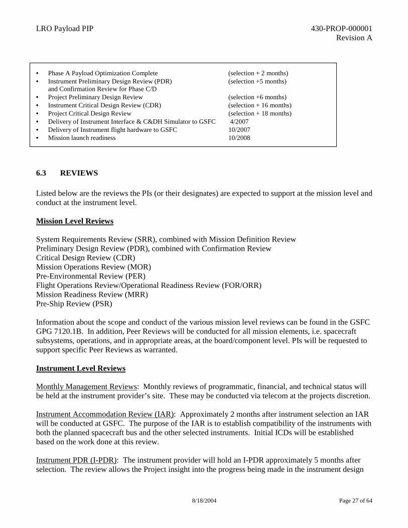
• Phase A Payload Optimization Complete (selection + 2 months)�• Instrument Preliminary Design Review (PDR) (selection +5 months)�
and Confirmation Review for Phase C/D �• Project Preliminary Design Review (selection +6 months)�• Instrument Critical Design Review (CDR) (selection + 16 months)�• Project Critical Design Review (selection + 18 months)�• Delivery of Instrument Interface & C&DH Simulator to GSFC 4/2007�• Delivery of Instrument flight hardware to GSFC 10/2007 • Mission launch readiness 10/2008
6.3 REVIEWS Listed below are the reviews the PIs (or their designates) are expected to support at the mission level and conduct at the instrument level. Mission Level Reviews System Requirements Review (SRR), combined with Mission Definition Review Preliminary Design Review (PDR), combined with Confirmation Review Critical Design Review (CDR) Mission Operations Review (MOR) Pre-Environmental Review (PER) Flight Operations Review/Operational Readiness Review (FOR/ORR) Mission Readiness Review (MRR) Pre-Ship Review (PSR) Information about the scope and conduct of the various mission level reviews can be found in the GSFC GPG 7120.1B. In addition, Peer Reviews will be conducted for all mission elements, i.e. spacecraft subsystems, operations, and in appropriate areas, at the board/component level. PIs will be requested to support specific Peer Reviews as warranted. Instrument Level Reviews Monthly Management Reviews: Monthly reviews of programmatic, financial, and technical status will be held at the instrument provider’s site. These may be conducted via telecom at the projects discretion. Instrument Accommodation Review (IAR): Approximately 2 months after instrument selection an IAR will be conducted at GSFC. The purpose of the IAR is to establish compatibility of the instruments with both the planned spacecraft bus and the other selected instruments. Initial ICDs will be established based on the work done at this review. Instrument PDR (I-PDR): The instrument provider will hold an I-PDR approximately 5 months after selection. The review allows the Project insight into the progress being made in the instrument design
LRO Payload PIP 430-PROP-000001 Revision A
8/18/2004 Page 28 of 64
and comparison to the planned performance and estimated margins. The findings will be reported at the mission level PDR. The Functional & Performance Requirements Document (F&PRD) and the ICDs will be presented and discussed at the I-PDR. The completed F&PRD and ICDs will be summarized and presented at the mission PDR. Instrument CDR (I-CDR): The last design review prior to initiating flight hardware fabrication (the project may approve long lead procurement prior to this) is the I-CDR. The instrument provider will conduct the I-CDR approximately 11 months after the I-PDR. Topics include status of hardware design, fabrication, test and calibration, software development and testing, integration plans, interface status, command and telemetry requirements, environmental testing plans and discussion flight operations planning. The results of Technical Peer Reviews must be included in the I-CDR. The findings of the I-CDR are reported at the mission CDR. Instrument Pre-Environmental Review: (I-PER): The instrument provider will hold an I-PER just prior to the start of instrument environmental testing. The focus of this review is to review the planned testing in detail and ascertain the readiness for the beginning of testing. Instrument Pre-Ship Review (I-PSR): Just prior to instrument delivery the instrument provider will conduct an I-PSR. The purpose will be to review the results of the environmental testing, compliance with the F&PRD and ICDs, and the completeness of the End Item Data Package (EIDP). Status and closure of pre-delivery problem/failure reports will also be reviewed. The I-PSR will conclude with the certification of readiness for shipment or identification of open work that must be completed before shipment. Flight Operations Review/Operational Readiness Review (FOR/ORR): The FOR/ORR is an integrated review that focuses on the operational readiness of the integrated instrument-MOT operations team. It includes hardware and facility readiness, a walk-through of uplink planning and the downlink analysis process, and a review of the data analysis software. Peer Reviews: The instrument development organization is expected to hold technical peer reviews for all instrument subsystems. The LRO Project Chief Systems Engineer or his designate from the project shall co-chair Peer Reviews.
6.4 DELIVERABLES In the following two sections the deliverables, along with preliminary delivery dates, that the PIs must provide are given.
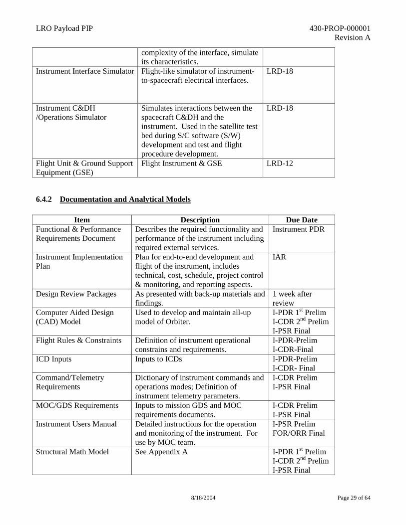
6.4.1 Hardware
Item Description Due Date Launch – X months (L-X)
Instrument Fit Check Template-I/F Simulator
Mechanical instrument interface simulator used to verify attachment interface and, if required by the
LRD-24
LRO Payload PIP 430-PROP-000001 Revision A
8/18/2004 Page 29 of 64
complexity of the interface, simulate its characteristics.
Instrument Interface Simulator Flight-like simulator of instrument-to-spacecraft electrical interfaces.
LRD-18
Instrument C&DH /Operations Simulator
Simulates interactions between the spacecraft C&DH and the instrument. Used in the satellite test bed during S/C software (S/W) development and test and flight procedure development.
LRD-18
Flight Unit & Ground Support Equipment (GSE)
Flight Instrument & GSE LRD-12
6.4.2 Documentation and Analytical Models
Item Description Due Date Functional & Performance Requirements Document
Describes the required functionality and performance of the instrument including required external services.
Instrument PDR
Instrument Implementation Plan
Plan for end-to-end development and flight of the instrument, includes technical, cost, schedule, project control & monitoring, and reporting aspects.
IAR
Design Review Packages As presented with back-up materials and findings.
1 week after review
Computer Aided Design (CAD) Model
Used to develop and maintain all-up model of Orbiter.
I-PDR 1st Prelim I-CDR 2nd Prelim I-PSR Final
Flight Rules & Constraints Definition of instrument operational constrains and requirements.
I-PDR-Prelim I-CDR-Final
ICD Inputs Inputs to ICDs I-PDR-Prelim I-CDR- Final
Command/Telemetry Requirements
Dictionary of instrument commands and operations modes; Definition of instrument telemetry parameters.
I-CDR Prelim I-PSR Final
MOC/GDS Requirements Inputs to mission GDS and MOC requirements documents.
I-CDR Prelim I-PSR Final
Instrument Users Manual Detailed instructions for the operation and monitoring of the instrument. For use by MOC team.
I-PSR Prelim FOR/ORR Final
Structural Math Model See Appendix A I-PDR 1st Prelim I-CDR 2nd Prelim I-PSR Final
LRO Payload PIP 430-PROP-000001 Revision A
8/18/2004 Page 30 of 64
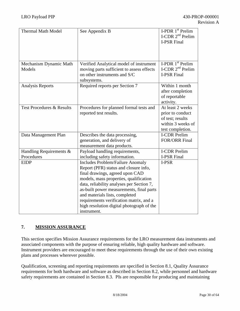
Thermal Math Model See Appendix B I-PDR 1st Prelim I-CDR 2nd Prelim I-PSR Final
Mechanism Dynamic Math Models
Verified Analytical model of instrument moving parts sufficient to assess effects on other instruments and S/C subsystems.
I-PDR 1st Prelim I-CDR 2nd Prelim I-PSR Final
Analysis Reports Required reports per Section 7 Within 1 month after completion of reportable activity.
Test Procedures & Results Procedures for planned formal tests and reported test results.
At least 2 weeks prior to conduct of test; results within 3 weeks of test completion.
Data Management Plan Describes the data processing, generation, and delivery of measurement data products.
I-CDR Prelim FOR/ORR Final
Handling Requirements & Procedures
Payload handling requirements, including safety information.
I-CDR Prelim I-PSR Final
EIDP Includes Problem/Failure Anomaly Report (PFR) status and closure info, final drawings, agreed upon CAD models, mass properties, qualification data, reliability analyses per Section 7, as-built power measurements, final parts and materials lists, completed requirements verification matrix, and a high resolution digital photograph of the instrument.
I-PSR
7. MISSION ASSURANCE This section specifies Mission Assurance requirements for the LRO measurement data instruments and associated components with the purpose of ensuring reliable, high quality hardware and software. Instrument providers are encouraged to meet these requirements through the use of their own existing plans and processes wherever possible. Qualification, screening and reporting requirements are specified in Section 8.1, Quality Assurance requirements for both hardware and software as described in Section 8.2, while personnel and hardware safety requirements are contained in Section 8.3. PIs are responsible for producing and maintaining
LRO Payload PIP 430-PROP-000001 Revision A
8/18/2004 Page 31 of 64
records, including test and analysis reports and other controlled records, sufficient to demonstrate compliance with the LRO Mission Assurance requirements. This data must be made available for review by the Robotic Lunar Exploration Program assurance office. Applicable sections will also be included in the instrument contract EIDPs.
7.1 QUALIFICATION, SCREENING AND REPORTING SERVICES Instrument providers must fully space-qualify hardware prior to delivery to GSFC in accordance with the requirements specified herein. In particular, developers will be required to conduct reliability analyses as specified in Section 8.1.1, conduct electronic parts screening and upgrades as specified in Section 8.1.2, screen flight hardware materials and submit hardware Materials Identification and Usage Lists (MIUL) as specified in Section 8.1.3, and conduct environmental qualification analysis and testing as delineated in Section 8.1.4. The developer must also meet contamination control, problem/failure reporting and operating hours requirements as discussed in Sections 8.1.5 through 8.1.7, respectively.
7.1.1 Reliability Analysis The developer is required to perform and submit for approval reliability engineering analyses of measurement data instrument payload hardware, which are to be conducted in accordance with standard established industry methods and the applicable documents in Section 1.2. Required analyses are listed below: Required for Flight Hardware: Failure Modes Effects and Criticality Analysis (FMECA) Electronic Parts Stress Analysis (PSA) Single Event Effects Analysis Instrument Reliability Assessment (includes prediction of Probability of Success (Ps)) Required for Ground Support Equipment (GSE): All GSE that interfaces with flight hardware shall be treated as flight hardware. An interface FMECA is required for GSE and must be conducted prior to mating such equipment to flight or engineering hardware. Schematics for flight and GSE hardware must be submitted to the Project Office as backup documentation to the FMECA. The flight hardware schematics will be used to support the spacecraft/observatory level FMECA activity. If a design is shown to have a failure mode that could propagate beyond the instrument interface, the Project Office may require implementation of corrective changes prior to the acceptance of the hardware.
7.1.2 Electrical, Electronic and Electromechanical Parts Screening of all Electrical, Electronic and Electromechanical (EEE) parts shall be conducted in accordance with Instructions for EEE parts Selection, Screening, Qualification and Derating, GSFC Document # EEE-INST-002.
LRO Payload PIP 430-PROP-000001 Revision A
8/18/2004 Page 32 of 64
All parts must meet or exceed any of the following standards: 1) NASA GSFC EEE-INST-002, level 2 2) MIL-PRF-19500 JANTXV, QML-19500 3) MIL-PRF-38534, Class H, QML-37534 (MIL-PRF-38510, Class B) with PIND, DPA and
radiographic upscreening 4) MIL-PRF-38535 Class Q, QML-38535 5) Military Established Reliability (ER) passive devices, Failure Rate Level R Parts not meeting minimum standards (883B parts, unique parts, custom parts such as Application Specific Integrated Circuits (ASICs), custom hybrids and all commercial parts) must be upscreened per above requirement. It is recognized that certain specialty devices may not be capable of compliance with these requirements. Any and all known or anticipated non-compliance should be reported as part of the proposal. Plastic parts should be avoided, but if required shall be screened and qualified in accordance with GSFC PEM-INST-001 and furthermore require approval by the Project. Radiation tolerance requirements and environments are discussed in Section 3.3.4 of this document.
Specifications and references associated with the EEE parts requirements are listed below:
1) GSFC EEE Parts Policy 2) NASA GSFC EEE-INST-002 Instructions for EEE Parts Selection, Screening, Qualification
and Derating 3) MIL-PRF-19500, General Specification for Semiconductor Devices 4) QML-19500, Qualified Products List of Products Qualified under MIL-PRF-19500, General
Specification for Semiconductor Devices 5) MIL-PRF-38534, General Specification for Hybrid Microcircuits 6) MIL-PRF-38510, General Specification for Microcircuits 7) MIL_PRF-38535, General Specification for Integrated Circuit (Microcircuit) Manufacturing 8) QML-38534, Qualified Manufacturers List of Custom Hybrid Microcircuits Manufactured to
the Requirements of MIL-PRF-38534 9) QML-38535, Qualified Manufacturers List of Integrated Circuits (Microcircuits)
Manufactured to the Requirements of MIL-PRF-38535 10) JPL D-19426, Plastic Encapsulated Microcircuits (PEMs) Reliability/Usage Guidelines for
Space Applications 11) JPL Publication 00-06, “An Introduction to Space Radiation Effects on Microelectronics.
LRO Payload PIP 430-PROP-000001 Revision A
8/18/2004 Page 33 of 64
7.1.3 Materials and Processes Submittal of MIUL will be required for all materials and processes, one month prior to PDR and CDR. Materials and processes will be reviewed by the project for compliance with the requirements in the following areas: Thermal vacuum stability and outgassing Shelf life limitations Flammability Radiation resistance Galvanic corrosion Electrical arc-tracking resistance Stress corrosion cracking Hazardous materials Weld process qualification Static charge sensitivity Non-destructive inspection requirements Fungus resistance Structural design allowables Fastener material and traceability Contributions to organic contamination In the event materials or processes do not meet GSFC screening, Material Usage Agreement (MUA) forms must be submitted to the Program Office for approval. In addition to “traditional” materials concerns, usage of materials containing organic materials similar to those that are pertinent to the mission measurement data investigation will also be monitored and/or limited.
7.1.4 Environmental Requirements Analysis Requirements Analyses must be conducted in a manner sufficient to demonstrate compatibility of deliverable hardware with radiation, venting, dynamic load, and thermal environments as indicated below. Radiation analysis: ability of instrument and payload electronics to operate adequately and reliably in the LRO mission environment must be shown by analysis. Electrical analysis shall be conducted in a manner sufficient to demonstrate the compatibility of the deliverable hardware with EMI/EMC, radiation, and thermal environments. Charging Analysis shall be conducted in a manner sufficient to demonstrate the compatibility of the deliverable hardware with EMI/EMC and radiation environments. Venting ability of instruments and payload electronics to survive the pressure decay environment associated with Earth launch must be shown by analysis. Stress and structural stability analysis to verify structural integrity must be conducted and documented per Appendix A of this document. Thermal Analysis to verify compatibility with expected environments must be conducted and documented per Appendix B of this document.
LRO Payload PIP 430-PROP-000001 Revision A
8/18/2004 Page 34 of 64
Test Requirements Testing of all fully assembled deliverable hardware, to appropriate Flight Acceptance, Protoflight or Qualification levels as defined in this document including Appendix A and the Goddard Environmental Verification Specification for Shuttle & ELV (GEVS-SE), must be successfully completed prior to instrument delivery. The instrument provider must submit test plans and a completed environmental test verification matrix to the LRO Project Office for approval prior to start of testing. Test data must be submitted to GSFC for review and closure of the environmental test verification matrix. Required environmental tests include:
1) Random vibration (force limiting recommended) 2) Sinusoidal vibration 3) Thermal-Vacuum and Thermal-Balance 4) EMI/EMC radiated & conducted emissions, susceptibility plus isolation 5) Thermal cycling life test (case-by-case basis)
Instruments shall be designed to withstand the pyrotechnic shock environment defined in Appendix A.
7.1.5 Contamination Control Specific contamination control requirements will be established after instrument selection to maintain the required cleanliness and prevent contamination of engineering hardware and instruments and, if required, to satisfy Planetary Protection strategies. Requirements will be established for the following:
1) Materials usage 2) Cleaning Processes 3) Surface Cleanliness 4) Outgassing and vacuum bake out 5) Hardware protection and storage 6) Facility cleanliness 7) Planetary Protection (if required, currently under NASA review)
7.1.6 Problem/Failure Anomaly Reporting Closed loop Problem/Failure anomaly Reporting is required for Flight Model (FM) and GSE hardware and software, and any other critical hardware. Critical hardware is defined as flight, flight spare, and GSE that interfaces with flight hardware. All problem/failure and anomaly reports shall be risk rated for failure effect and cause. Reporting shall occur through an approved contractor reporting system or the GSFC PFR system and must begin as shown below:
1) Flight electronics - first application of power at the board level 2) Engineering model electronics - start of subsystem qualification, or first board level
power on is Engineering Model (EM) is to be used as a flight spare 3) Instruments - First application of power at instrument level
LRO Payload PIP 430-PROP-000001 Revision A
8/18/2004 Page 35 of 64
4) GSE - First functional test at delivery of assembly 5) Software - first interaction with flight or EM hardware 6) Mechanical hardware - start of qualification testing 7) EEE parts - immediately following problem or failure 8) Printed Wiring Board (PWB) coupons - immediately following test report from GSFC
The LRO Project office shall be notified within 24 hours of any PFR/Anomaly on critical or flight hardware. The PI team is responsible for maintaining a matrix of all PFRs and their status. This matrix will be presented with monthly management reports. Closure of pre-delivery PFRs will be included in the instrument delivery review.
7.1.7 Hardware/Software Failure Free Operating Hours Measurement data instruments and payload elements shall have accumulated 250 hours of failure free operation prior to delivery to spacecraft integration.
7.2 QUALITY ASSURANCE REQUIREMENTS
7.2.1 Hardware Quality Assurance All hardware providers and contractors must be certified to or compliant with ISO 9001. Hardware providers must demonstrate capabilities in these critical processes (where applicable): Plating Welding Die attachment Radiographic inspection Anodizing Soldering Wire bonding Ultrasonic inspection Heat treating Cleaning Magnetic particle inspection Liquid penetrant inspection Quality records including manufacturing planning records, detailed steps performed, inspection points, test logs, non-conformance documents, parts lists, engineering changes, etc, must be retained for all hardware and furnished to the LRO Project office. A manufacturing fabrication and flow plan detailing who is building what, where and when is also required to be maintained up to date. Full traceability to the individual part level must be maintained on all hardware designated as flight, flight spare, or ground support equipment that interfaces with flight hardware. Controlled documents including test plans and procedures, drawings and specifications must be maintained and properly stored. Hardware non-conformances must be identified and corrected through a closed loop system. Test and assembly operations must be conducted in accordance with a written configuration controlled test plan, which includes step-by-step assembly instruction data sheets (or contractor equivalent) for all critical hardware (as defined in Section 8.1.6). All tests (environmental, acceptance and functional) involving critical hardware must include Quality Assurance (QA) survey and approval of test set up and QA witness of test operations.
7.2.2 Software Quality Assurance Development processes associated with measurement data instrument and payload article software must be compliant with NASA Software Policies, NPD 2820.1. Software requirements must be documented
LRO Payload PIP 430-PROP-000001 Revision A
8/18/2004 Page 36 of 64
and traceable to S/W design implementation, system and subsystem interface requirements and S/W validation tests. Software developers/providers must maintain objective evidence (verification matrices, test records, reports, memos, meeting minutes, etc) of requirement compliance. Measurement data software/firmware running on spacecraft flight computer is subject to additional reviews, analysis and verification requirements beyond those required for instrument software that is internal to a measurement data instrument. These additional requirements will be supplied if required. All software/firmware destined for Instrument Qualification (Protoflight), Flight or Flight Spares is subject to the following verification requirements:
1) Accuracy of as-built product identification 2) Proper test Plan/Procedure/Reports release 3) Existence and adequacy of an Installation manual 4) List of software deliverables including all required documents (under configuration
management (CM) control) 5) Software System requirements test traceability matrix 6) List of open/closed PFRs, liens against the current release of software.
Software safety/hazard analyses and audits will be conducted by GSFC to verify that output values and/or timing do not place the system in a hazardous state, and to ensure that the software responds appropriately under hardware failure scenarios.
7.3 SAFETY Formal safety inspections and audits of facilities, including facility safety and pre-test hazard assessments will be conducted by the GSFC Systems Safety Office, or an approved Safety office at the PI/Contractor facility. Any action items missing from audits will be addressed prior to testing or assembly operations involving critical hardware.
8. PRE-DELIVERY INTEGRATED TESTING AND POST-DELIVERY INTEGRATION
8.1 PRE-DELIVERY INTERFACE VERIFICATION Prior to instrument delivery, and as soon as practical, a high fidelity interface verification test will be conducted at the instrument developers facility using the flight instrument and a spacecraft C&DH/Power interface simulator supplied and supported by the project.
8.2 POST-DELIVERY INTEGRATION AND TEST The major LRO integration and test activities that will occur after instrument delivery to GSFC are listed below. The instrument development team is required to support these activities.
• Incoming inspection and cleaning • Instrument mass and CM measurement
LRO Payload PIP 430-PROP-000001 Revision A
8/18/2004 Page 37 of 64
• Instrument functional testing (Instrument GSE may be required) • Mechanical integration and alignment of instruments • Safe-to-mate instrument electrical interface testing • Electrical integration of instruments • Functional & mission simulation testing • Mass properties measurement and spin balance (if required) • Thermal Blanket closeouts • EMI/EMC testing • Vibro-acoustic & loads testing • Thermal-vacuum and thermal balance testing • Pre-ship final functional testing
8.3 LAUNCH SITE OPERATIONS The major LRO launch site activities that will occur after shipment to the launch site are listed below. The instrument development team is required to support these activities and any contingency operations that may be required.
• Post-ship functional testing • Propulsion system fueling • Final spin balancing (if required) • Abbreviated functional testing • Integration to launch vehicle • Final Closeouts, cover removals, and walk-down • Launch
9. COST GUIDELINES The current budget guideline for the LRO payload is $90M for development thru the end of the one-year primary mission (phases A-E). Allocations for individual instruments will be determined at selection. Phasing has yet to be determined but it is anticipated that the initial year after selection will be modestly funded and PIs are urged to plan accordingly.
Each measurement investigation budget must include reserves to be managed by the individual proposers. The strategy for the derivation and management of cost reserves must be included in the proposal. The project recommends a 30% cost reserve level. Proposal of other levels of reserves must include the comprehensive rationale for the level proposed.
LRO Payload PIP 430-PROP-000001 Revision A
8/18/2004 Page 38 of 64
Appendix A
Structural Loads and Mechanical Environments Specification for The Lunar Reconnaissance Orbiter (LRO)
Preliminary Release
LRO Payload PIP 430-PROP-000001 Revision A
8/18/2004 Page 39 of 64
Prepared by: _________________________________________ ________ Leslie Hartz, Structural Analysis Lead Date Approved by: _________________________________________ ________ Craig Tooley, Project Manager Date _________________________________________ ________ Jim Watzin, Program Manager Date
LRO Payload PIP 430-PROP-000001 Revision A
8/18/2004 Page 40 of 64
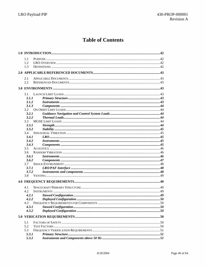
Table of Contents
1.0 INTRODUCTION................................................................................................................................42
1.1 PURPOSE ......................................................................................................................................42 1.2 LRO OVERVIEW ..........................................................................................................................42 1.3 DEFINITIONS ................................................................................................................................42
2.0 APPLICABLE/REFERENCED DOCUMENTS...............................................................................43
2.1 APPLICABLE DOCUMENTS............................................................................................................43 2.2 REFERENCED DOCUMENTS...........................................................................................................43
3.0 ENVIRONMENTS ..............................................................................................................................43
3.1 LAUNCH LIMIT LOADS .................................................................................................................43 3.1.1 Primary Structure ............................................................................................................43 3.1.2 Instruments ......................................................................................................................43 3.1.3 Components .....................................................................................................................44
3.2 ON ORBIT LIMIT LOADS...............................................................................................................44 3.2.1 Guidance Navigation and Control System Loads...........................................................44 3.2.2 Thermal Loads.................................................................................................................44
3.3 MGSE LIMIT LOADS ...................................................................................................................44 3.3.1 Strength............................................................................................................................44 3.3.2 Stability ............................................................................................................................45
3.4 SINUSOIDAL VIBRATION ..............................................................................................................45 3.4.1 LRO..................................................................................................................................45 3.4.2 Instruments ......................................................................................................................45 3.4.3 Components .....................................................................................................................45
3.5 ACOUSTICS ..................................................................................................................................46 3.6 RANDOM VIBRATION ...................................................................................................................46
3.6.1 Instruments ......................................................................................................................46 3.6.2 Components .....................................................................................................................47
3.7 SHOCK ENVIRONMENT.................................................................................................................48 3.7.1 LRO/PAF Interface .........................................................................................................48 3.7.2 Instruments and components ..........................................................................................48
3.8 VENTING......................................................................................................................................49
4.0 FREQUENCY REQUIREMENTS.....................................................................................................49
4.1 SPACECRAFT PRIMARY STRUCTURE.............................................................................................49 4.2 INSTRUMENTS ..............................................................................................................................49
4.2.1 Stowed Configuration......................................................................................................49 4.2.2 Deployed Configuration ..................................................................................................50
4.3 FREQUENCY REQUIREMENTS FOR COMPONENTS .........................................................................50 4.3.1 Stowed Configuration......................................................................................................50 4.3.2 Deployed Configuration ..................................................................................................50
5.0 VERICATION REQUIREMENTS....................................................................................................50
5.1 FACTORS OF SAFETY....................................................................................................................50 5.2 TEST FACTORS .............................................................................................................................50 5.3 FREQUENCY VERIFICATION REQUIREMENTS................................................................................51
5.3.1 Primary Structure ............................................................................................................51 5.3.2 Instruments and Components above 50 Hz ....................................................................51
LRO Payload PIP 430-PROP-000001 Revision A
8/18/2004 Page 41 of 64
5.3.3 Instruments and Components below 50 Hz ....................................................................51
6.0 FINITE ELEMENT MODEL (FEM) REQUIREMENTS...............................................................52
6.1 FEM DOCUMENTATION ...............................................................................................................52 6.2 FEM SUBMITTAL.........................................................................................................................52
LRO Payload PIP 430-PROP-000001 Revision A
8/18/2004 Page 42 of 64
Introduction
Purpose The Lunar Reconnaissance Orbiter (LRO) mission objective is to conduct investigations that will be specifically targeted to characterize future lunar landing sites and identify potential resources in support of NASA’s Exploration Initiative. This LRO Loads and Environments Specification defines the limit loads, mechanical environments, and mechanical verification requirements of the LRO spacecraft, and its instruments, components and ground support equipment. This document is part of the Proposal Information Package. All loads and environments in this document are preliminary and will be updated as the LRO spacecraft is defined.
LRO Overview The LRO mission will be launched from KSC on a Delta II class ELV into a low altitude parking orbit and then injected into a lunar trajectory by the ELV’s second or third stage. After a trans-lunar trajectory phase of approximately 100 hours the spacecraft will be inserted into lunar orbit using the on-board propulsion system. The primary mission will be conducted in a circular polar mapping orbit with an altitude of 30-50 km for one earth year. The 3-axis stabilized spacecraft will fly a nadir-pointing attitude with off-nadir maneuvers if required by the observing instruments.
Definitions Qualification Test: A test performed on non-flight hardware. The purpose of the test is to prove that a new design meets one or more of its design requirements. Qualification testing is performed at maximum expected flight levels plus a margin. Test durations are typically longer than for acceptance tests. Protoflight Test: A test performed on flight hardware. The purpose of the test is to prove that a new design meets one or more of its design requirements. Protoflight testing is performed at maximum expected flight levels plus a margin. Test durations are typically the same as for acceptance tests. Acceptance Test: A test performed on flight hardware. The purpose of this test is to prove that a particular flight unit has been manufactured properly. The design has already been proven during a qualification or protoflight test program. Acceptance testing is performed at maximum expected flight levels. Instrument: A component consisting of sensors and/or optical hardware used for making measurements or observations. For the purpose of this document instruments are distinguished from components. Component: A component is a self-contained combination of items performing a function. Examples are electronic box, transmitter, gyro package, motor, and battery. For the purposes of this document, the term component is used generically to represent an analyzable or testable level of assembly below the observatory level.
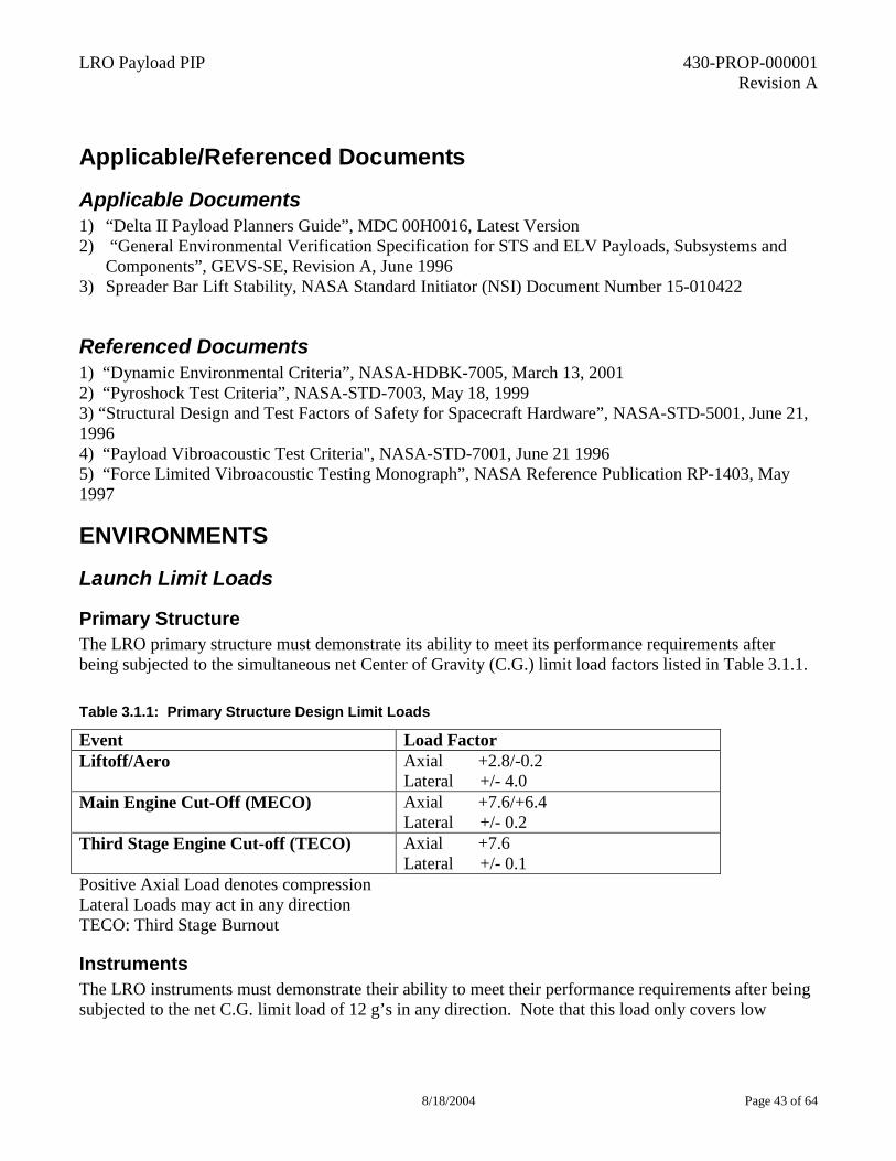
LRO Payload PIP 430-PROP-000001 Revision A
8/18/2004 Page 43 of 64
Applicable/Referenced Documents
Applicable Documents 1) “Delta II Payload Planners Guide”, MDC 00H0016, Latest Version 2) “General Environmental Verification Specification for STS and ELV Payloads, Subsystems and
Components”, GEVS-SE, Revision A, June 1996 3) Spreader Bar Lift Stability, NASA Standard Initiator (NSI) Document Number 15-010422
Referenced Documents 1) “Dynamic Environmental Criteria”, NASA-HDBK-7005, March 13, 2001 2) “Pyroshock Test Criteria”, NASA-STD-7003, May 18, 1999 3) “Structural Design and Test Factors of Safety for Spacecraft Hardware”, NASA-STD-5001, June 21, 1996 4) “Payload Vibroacoustic Test Criteria", NASA-STD-7001, June 21 1996 5) “Force Limited Vibroacoustic Testing Monograph”, NASA Reference Publication RP-1403, May 1997
ENVIRONMENTS
Launch Limit Loads
Primary Structure The LRO primary structure must demonstrate its ability to meet its performance requirements after being subjected to the simultaneous net Center of Gravity (C.G.) limit load factors listed in Table 3.1.1. Table 3.1.1: Primary Structure Design Limit Loads
Event Load Factor Liftoff/Aero Axial +2.8/-0.2
Lateral +/- 4.0 Main Engine Cut-Off (MECO) Axial +7.6/+6.4
Lateral +/- 0.2 Third Stage Engine Cut-off (TECO) Axial +7.6
Lateral +/- 0.1 Positive Axial Load denotes compression Lateral Loads may act in any direction TECO: Third Stage Burnout
Instruments The LRO instruments must demonstrate their ability to meet their performance requirements after being subjected to the net C.G. limit load of 12 g’s in any direction. Note that this load only covers low
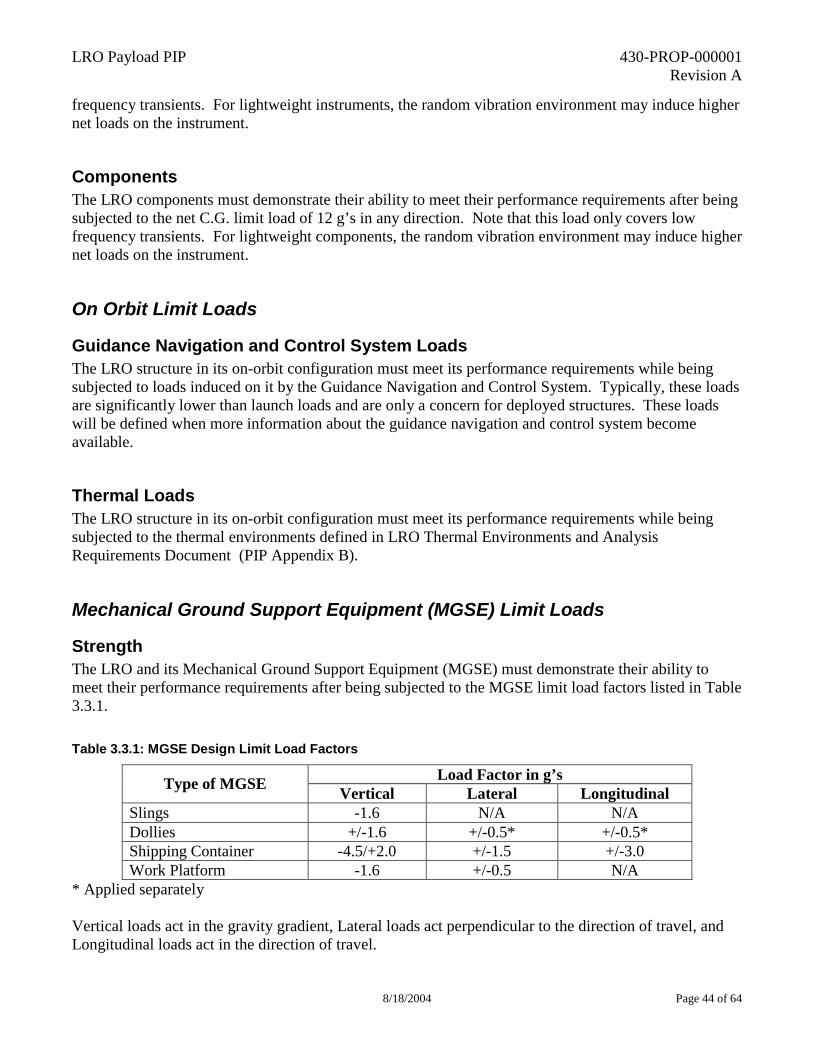
LRO Payload PIP 430-PROP-000001 Revision A
8/18/2004 Page 44 of 64
frequency transients. For lightweight instruments, the random vibration environment may induce higher net loads on the instrument.
Components The LRO components must demonstrate their ability to meet their performance requirements after being subjected to the net C.G. limit load of 12 g’s in any direction. Note that this load only covers low frequency transients. For lightweight components, the random vibration environment may induce higher net loads on the instrument.
On Orbit Limit Loads
Guidance Navigation and Control System Loads The LRO structure in its on-orbit configuration must meet its performance requirements while being subjected to loads induced on it by the Guidance Navigation and Control System. Typically, these loads are significantly lower than launch loads and are only a concern for deployed structures. These loads will be defined when more information about the guidance navigation and control system become available.
Thermal Loads The LRO structure in its on-orbit configuration must meet its performance requirements while being subjected to the thermal environments defined in LRO Thermal Environments and Analysis Requirements Document (PIP Appendix B).
Mechanical Ground Support Equipment (MGSE) Limit Loads
Strength The LRO and its Mechanical Ground Support Equipment (MGSE) must demonstrate their ability to meet their performance requirements after being subjected to the MGSE limit load factors listed in Table 3.3.1. Table 3.3.1: MGSE Design Limit Load Factors
Load Factor in g’s Type of MGSE Vertical Lateral Longitudinal Slings -1.6 N/A N/A Dollies +/-1.6 +/-0.5* +/-0.5* Shipping Container -4.5/+2.0 +/-1.5 +/-3.0 Work Platform -1.6 +/-0.5 N/A
* Applied separately Vertical loads act in the gravity gradient, Lateral loads act perpendicular to the direction of travel, and Longitudinal loads act in the direction of travel.
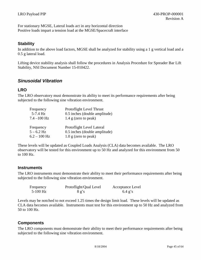
LRO Payload PIP 430-PROP-000001 Revision A
8/18/2004 Page 45 of 64
For stationary MGSE, Lateral loads act in any horizontal direction Positive loads impart a tension load at the MGSE/Spacecraft interface
Stability In addition to the above load factors, MGSE shall be analyzed for stability using a 1 g vertical load and a 0.5 g lateral load. Lifting device stability analysis shall follow the procedures in Analysis Procedure for Spreader Bar Lift Stability, NSI Document Number 15-010422.
Sinusoidal Vibration
LRO The LRO observatory must demonstrate its ability to meet its performance requirements after being subjected to the following sine vibration environment. Frequency Protoflight Level Thrust 5-7.4 Hz 0.5 inches (double amplitude) 7.4 –100 Hz 1.4 g (zero to peak) Frequency Protoflight Level Lateral 5 – 6.2 Hz 0.5 inches (double amplitude) 6.2 – 100 Hz 1.0 g (zero to peak) These levels will be updated as Coupled Loads Analysis (CLA) data becomes available. The LRO observatory will be tested for this environment up to 50 Hz and analyzed for this environment from 50 to 100 Hz.
Instruments The LRO instruments must demonstrate their ability to meet their performance requirements after being subjected to the following sine vibration environment. Frequency Protoflight/Qual Level Acceptance Level 5-100 Hz 8 g’s 6.4 g’s Levels may be notched to not exceed 1.25 times the design limit load. These levels will be updated as CLA data becomes available. Instruments must test for this environment up to 50 Hz and analyzed from 50 to 100 Hz.
Components The LRO components must demonstrate their ability to meet their performance requirements after being subjected to the following sine vibration environment.
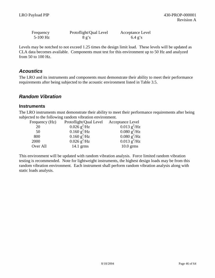
LRO Payload PIP 430-PROP-000001 Revision A
8/18/2004 Page 46 of 64
Frequency Protoflight/Qual Level Acceptance Level 5-100 Hz 8 g’s 6.4 g’s Levels may be notched to not exceed 1.25 times the design limit load. These levels will be updated as CLA data becomes available. Components must test for this environment up to 50 Hz and analyzed from 50 to 100 Hz.
Acoustics The LRO and its instruments and components must demonstrate their ability to meet their performance requirements after being subjected to the acoustic environment listed in Table 3.5.
Random Vibration
Instruments The LRO instruments must demonstrate their ability to meet their performance requirements after being subjected to the following random vibration environment. Frequency (Hz) Protoflight/Qual Level Acceptance Level
20 0.026 g2/Hz 0.013 g2/Hz 50 0.160 g2/Hz 0.080 g2/Hz 800 0.160 g2/Hz 0.080 g2/Hz 2000 0.026 g2/Hz 0.013 g2/Hz Over All 14.1 grms 10.0 grms
This environment will be updated with random vibration analysis. Force limited random vibration testing is recommended. Note for lightweight instruments, the highest design loads may be from this random vibration environment. Each instrument shall perform random vibration analysis along with static loads analysis.
LRO Payload PIP 430-PROP-000001 Revision A
8/18/2004 Page 47 of 64
Table 3.5: Delta II Acoustic Environment
The reference point 20 µPa
Components The LRO components must demonstrate their ability to meet their performance requirements after being subjected to the following random vibration environment. Frequency (Hz) Protoflight/Qual Level Acceptance Level
20 0.026 g2/Hz 0.013 g2/Hz
Center Frequency (Hz) Protoflight/Qual Sound Pressure Level (dB)
Acceptance Sound Pressure Level (dB)
31.5 124.5 121.5 40 127.0 124.0 50 130.0 127.0 63 129.5 127.5 80 130.2 127.2 100 132.5 129.5 125 133.5 130.5 160 134.0 131.0 200 135.0 132.0 250 136.0 133.0 315 138.0 135.0 400 142.0 139.0 500 143.5 140.5 630 141.0 138.0 800 136.0 133.0 1000 134.0 131.0 1250 133.5 130.5 1600 133.5 130.5 2000 131.5 128.5 2500 130.0 127.0 3150 130.0 127.0 4000 128.0 125.0 5000 127.0 124.0 6300 123.5 120.5 8000 122.5 119.5 10000 121.5 118.5
Overall Sound Pressure Level (OASPL)
149.6 146.6
LRO Payload PIP 430-PROP-000001 Revision A
8/18/2004 Page 48 of 64
50 0.160 g2/Hz 0.080 g2/Hz 800 0.160 g2/Hz 0.080 g2/Hz 2000 0.026 g2/Hz 0.013 g2/Hz Over All 14.1 grms 10.0 grms
This environment will be updated with random vibration analysis. Note for lightweight components, the highest design loads may be from this random vibration environment. Each instrument shall perform random vibration analysis along with static loads analysis.
Shock Environment
LRO/Payload Attach Fitting (PAF) Interface The maximum expected shock environment at the LRO/adapter is defined in Figure 3.7.1. LRO/PAF interface shock testing will be performed on the LRO Observatory.
TBD Figure
Figure 3.7.1: LRO/PAF Interface Shock Spectrum
Instruments and components The maximum expected shock environment from the LRO Observatory at instrument and component interfaces is shown in figure 3.7.2. This shock environment will be updated. Instruments and components will be tested for this environment at the observatory level. Instruments and components that have self induced shock environments must test qualified for this environment prior to delivery to the LRO observatory.
Figure 3.7.2: Instrument and Component Shock Spectrum
Shock Response Spectrum
10
100
1000
10000
10 100 1000 10000
Frequency (Hz)
Peak
Acc
eler
atio
n R
espo
nse
(g)
67 g
800 Hz
2000 g
5000 Hz
LRO Payload PIP 430-PROP-000001 Revision A
8/18/2004 Page 49 of 64
Venting The LRO observatory and its instruments and components must be able to withstand the pressure profile in Figure 3.8.1.
Figure 3.8.1 Delta II Payload Fairing Compartment Absolute Pressure Envelope
FREQUENCY REQUIREMENTS
Spacecraft Primary Structure LRO shall have a lateral fundamental frequency greater than 15 Hertz and thrust axis fundamental frequency greater than 35 Hertz when hard mounted to its Payload Adapter fitting interface.
Instruments
Stowed Configuration The LRO instruments in their stowed configuration must have a frequency greater than 35 Hz when mounted at their spacecraft interface. A minimum frequency goal of 50 Hz is recommended. This simplifies loads predictions and usually results in lower more stable structural loads. It also insures that the hard requirement of 35 Hz is met.
LRO Payload PIP 430-PROP-000001 Revision A
8/18/2004 Page 50 of 64
Deployed Configuration The LRO instruments shall have a deployed frequency greater than 3 Hz in their deployed configuration when hard mounted at their spacecraft interface.
Frequency Requirements for Components
Stowed Configuration The LRO components in their stowed configuration shall have a frequency greater than 50 Hz when hard mounted at their spacecraft interface.
Deployed Configuration The LRO components shall have a deployed frequency greater than 3 Hz in their deployed configuration when hard mounted at their spacecraft interface.
VERICATION REQUIREMENTS
Factors of Safety The LRO structure, instruments, and components as well as MGSE shall demonstrate positive Margins of Safety for all yield and ultimate failures using the Factors of Safety (FS) defined in Table 5.1. Table 5.1: Factors of Safety
Design Factor of Safety Type of Hardware Yield Ultimate Tested Flight Structure – metallic 1.25 1.4 Tested Flight Structure – beryllium 1.4 1.6 Tested Flight Structure – composite* N/A 1.5 Pressure Loaded Structure 1.25 1.5 Pressure Lines and Fittings 1.25 4.0 Untested Flight Structure – metallic only 2.0 2.6 Ground Support Equipment 3.0 5.0 Transportation Dolly/Shipping Container 2.0 3.0
*All composite structures must be tested to 1.25 x limit loads Margin of Safety (MS) is defined as follows: MS = (Allowable Stress(or Load)/(Applied Limit Stress(or Load) x FS)) –1
Test Factors Test factors and durations for prototype, protoflight, and flight hardware are given in the Table 5.2. Hardware definitions are included later in this section.
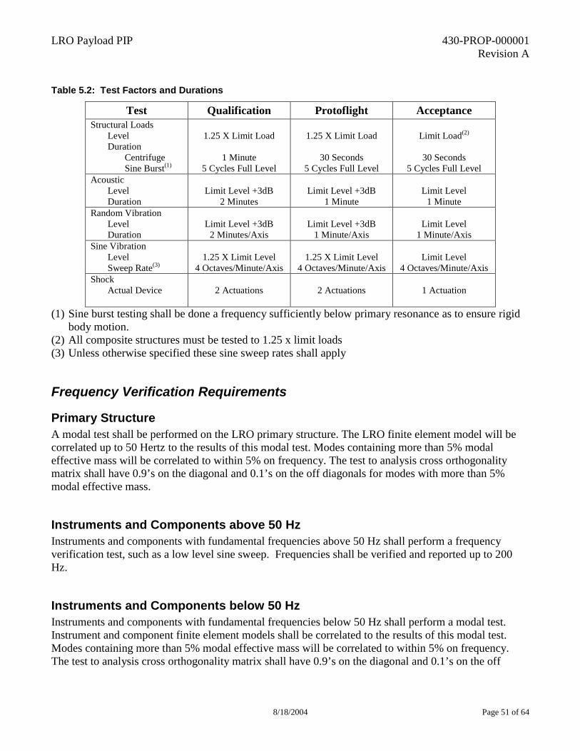
LRO Payload PIP 430-PROP-000001 Revision A
8/18/2004 Page 51 of 64
Table 5.2: Test Factors and Durations
Test Qualification Protoflight Acceptance Structural Loads
Level Duration
Centrifuge Sine Burst(1)
1.25 X Limit Load
1 Minute
5 Cycles Full Level
1.25 X Limit Load
30 Seconds
5 Cycles Full Level
Limit Load(2)
30 Seconds
5 Cycles Full Level Acoustic
Level Duration
Limit Level +3dB
2 Minutes
Limit Level +3dB
1 Minute
Limit Level
1 Minute Random Vibration
Level Duration
Limit Level +3dB
2 Minutes/Axis
Limit Level +3dB
1 Minute/Axis
Limit Level
1 Minute/Axis Sine Vibration
Level Sweep Rate(3)
1.25 X Limit Level
4 Octaves/Minute/Axis
1.25 X Limit Level
4 Octaves/Minute/Axis
Limit Level
4 Octaves/Minute/Axis Shock
Actual Device
2 Actuations
2 Actuations
1 Actuation
(1) Sine burst testing shall be done a frequency sufficiently below primary resonance as to ensure rigid
body motion. (2) All composite structures must be tested to 1.25 x limit loads (3) Unless otherwise specified these sine sweep rates shall apply
Frequency Verification Requirements
Primary Structure A modal test shall be performed on the LRO primary structure. The LRO finite element model will be correlated up to 50 Hertz to the results of this modal test. Modes containing more than 5% modal effective mass will be correlated to within 5% on frequency. The test to analysis cross orthogonality matrix shall have 0.9’s on the diagonal and 0.1’s on the off diagonals for modes with more than 5% modal effective mass.
Instruments and Components above 50 Hz Instruments and components with fundamental frequencies above 50 Hz shall perform a frequency verification test, such as a low level sine sweep. Frequencies shall be verified and reported up to 200 Hz.
Instruments and Components below 50 Hz Instruments and components with fundamental frequencies below 50 Hz shall perform a modal test. Instrument and component finite element models shall be correlated to the results of this modal test. Modes containing more than 5% modal effective mass will be correlated to within 5% on frequency. The test to analysis cross orthogonality matrix shall have 0.9’s on the diagonal and 0.1’s on the off
LRO Payload PIP 430-PROP-000001 Revision A
8/18/2004 Page 52 of 64
diagonals for modes with more than 5% modal effective mass. Frequencies between 50 and 200 Hz shall be verified and reported.
FINITE ELEMENT MODEL (FEM) REQUIREMENTS Instruments and components with predicted first frequencies below 75 Hz shall provide FEM’s for LRO structural analysis. These FEM’s have the following requirements.
FEM Documentation Each formal finite element model submittal shall companied by documentation that describes the following: 1. The version of the model. 2. A list of element, node, property, and material ID numbers. 3. A description of the nonstructural mass represented on each property card. 4. A description of units. 5. A description of the local reference coordinate system. 6. The results of validity checks. 7. Mass Properties (Center of Gravity (CG) location, Inertias, and total model mass). 8. Eight rigid-base mode frequencies.
FEM Submittal Formal finite element model submittals shall adhere to the following:
1. Model submitted as a MSC/NASTRAN data deck. 2. Model file name include the date (YYMMDD) that they were made at the beginning of their
name. 3. All model property and material cards have descriptive names. 4. Models submission is "full" model with no symmetry assumptions made to reduce model size. 5. Model includes no "Super Elements". 6. Model submission includes an explicit Single Part Constraint (SPC) set. 7. Until actual hardware mass properties are verified and final, the finite element model is adjusted
to the maximum allocated mass for each subsystem and component. 8. Model passes the following validity checks: unit enforced displacement and rotation, free-free
dynamics with equilibrium check, and unit gravity loading. 9. Finite element models used for thermal analysis pass a unit increased temperature check.
LRO Payload PIP 430-PROP-000001 Revision A
8/18/2004 Page 53 of 64
Appendix B
LRO Instrument Thermal Modeling, Analysis, and Testing Requirements
LRO Payload PIP 430-PROP-000001 Revision A
8/18/2004 Page 54 of 64
LRO AO PIP Appendix B
LRO Instrument Thermal Modeling and Analysis Requirements, Preliminary Release
1.0 THERMAL MODEL REQUIREMENTS
The contractor shall provide the LRO instrument geometric model as a Thermal Synthesizer System (TSS) Geometric model and a thermal math models in SINDA 85 format. LRO instrument Reduced Geometric Math Model (RGMM) and the Reduced Thermal Math Model (RTMM) shall be documented in a User's Manual. The User's Manual shall have sufficient documentation and figures of the model shall be provided for independent analysis runs. LRO instrument RGMM/RTMM shall contain NO VENDOR PROPRIETARY SOFTWARE. All RTMM special programs for control algorithms such as heater logic, VCHP logic, CPL/LHP logic et al shall be provided as part of model delivery. The deliverable RGMM/RTMMs of the LRO instrument shall be correlated to the detailed thermal models within 2°C for critical node/components. RGMM shall be less than 50 nodes and less than 50 surfaces.
• The thermal math models shall demonstrate that all LRO interfaces and LRO instrument thermal requirements are met for all modes of operation.
• The thermal math models shall be capable of steady state and transient prediction over all expected temperature ranges.
• The thermal math models shall be capable of calculating the heat transferred within the LRO instrument and exchanged with attached hardware (e.g., radiative exchange and conductive).
• The Watts, meters, kilograms, degrees Celsius, and Joules shall be the system of units for all models, except when the LRO Project approves other consistent systems of units.
• The thermal models shall include any LRO Project provided thermal models and associated geometric surface models of LRO provided hardware if necessary to make the model predict accurately.
• All thermal material and optical properties shall be consistent with the material and optical properties databases maintained by the LRO Projects. The contractor shall document any properties unique to the LRO instrument (i.e. not in the project database).
• Thermal models must contain comprehensive comments within the listings. Descriptions of nodes, masses, materials, thermo-physical and thermo-optical properties, conductive and radiative couplings, key assumptions, heater locations, power dissipations, should be evident within the model listings. All geometric surface models used to provide radiation interchange factors for the detailed thermal math models should also be similarly commented. Input and output units shall be clearly specified.
LRO Payload PIP 430-PROP-000001 Revision A
8/18/2004 Page 55 of 64
Thermal Model Validation The model shall be validated via correlation with thermal test results. The correlation required shall be documented and provided along with a comparison of model predictions with test results.
Thermal Model Documentation and Data Files The contractor shall provide a report describing the LRO instrument thermal design and the RGMM/RTMM. The thermal model documentation and data files shall be delivered on one or more compact disks to the LRO Project. Thermal model documentation shall be in Microsoft Word compatible format. Included in this report shall be the following:
a. Provide the following temperature limits:
• Temperature limits necessary for adequate operational performance.
• Temperature limits for which catastrophic failure occurs.
• Temperature limits for non-operational shipment or storage.
b. Provide the following temperature gradient limits:
• The temperature gradient constraints required for the spacecraft-mounting (conductive sink) surfaces and the rationale for the requirements.
• The temperature gradient constraints required between identified spacecraft radiative surfaces (radiative sink) and the rationale for the requirements.
c. Provide the following power dissipation information:
• An accurate definition of the power required and the power dissipated as heat in the parts and/or electronics subassemblies is required for the following conditions:
- Operating flight steady-state conditions.
- Non-operating flight steady-state heater dissipation at minimum bus voltage, Vdc (TBR).
- Maximum transient (peak) flight operating power duration and frequency.
• The location of the dissipated power (as heat) is to be identified to its corresponding part and/or electronics subassembly level and is to be related to the analytical model node number(s).
• The power, control bank (ON/OFF) and the location (related to analytical model node number) are required for any thermal control heaters both operational and survival that are placed to maintain required temperatures. In addition, any heater logic required for control shall be provided in the thermal model.
d. Provide the following mechanical properties:
• The LRO instrument assembly weight, size, and volume must be given with the relevant uncertainties.
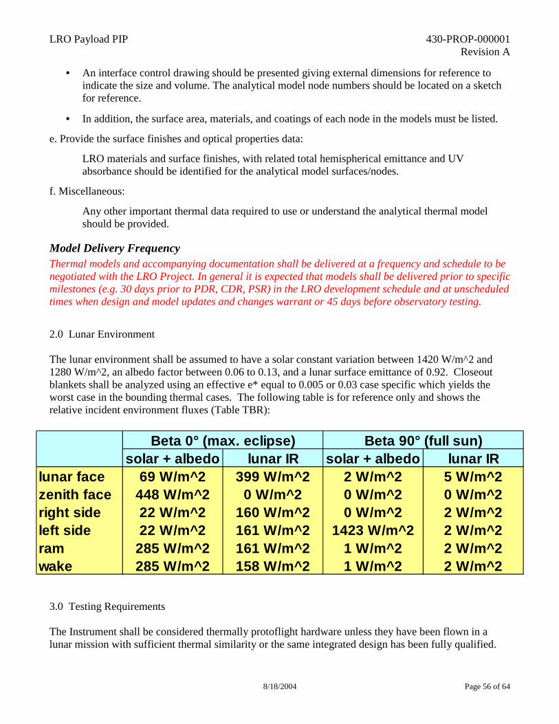
LRO Payload PIP 430-PROP-000001 Revision A
8/18/2004 Page 56 of 64
• An interface control drawing should be presented giving external dimensions for reference to indicate the size and volume. The analytical model node numbers should be located on a sketch for reference.
• In addition, the surface area, materials, and coatings of each node in the models must be listed.
e. Provide the surface finishes and optical properties data:
LRO materials and surface finishes, with related total hemispherical emittance and UV absorbance should be identified for the analytical model surfaces/nodes.
f. Miscellaneous:
Any other important thermal data required to use or understand the analytical thermal model should be provided.
Model Delivery Frequency Thermal models and accompanying documentation shall be delivered at a frequency and schedule to be negotiated with the LRO Project. In general it is expected that models shall be delivered prior to specific milestones (e.g. 30 days prior to PDR, CDR, PSR) in the LRO development schedule and at unscheduled times when design and model updates and changes warrant or 45 days before observatory testing.
2.0 Lunar Environment The lunar environment shall be assumed to have a solar constant variation between 1420 W/m^2 and 1280 W/m^2, an albedo factor between 0.06 to 0.13, and a lunar surface emittance of 0.92. Closeout blankets shall be analyzed using an effective e* equal to 0.005 or 0.03 case specific which yields the worst case in the bounding thermal cases. The following table is for reference only and shows the relative incident environment fluxes (Table TBR):
3.0 Testing Requirements The Instrument shall be considered thermally protoflight hardware unless they have been flown in a lunar mission with sufficient thermal similarity or the same integrated design has been fully qualified.
solar + albedo lunar IR solar + albedo lunar IRlunar face 69 W/m^2 399 W/m^2 2 W/m^2 5 W/m^2zenith face 448 W/m^2 0 W/m^2 0 W/m^2 0 W/m^2right side 22 W/m^2 160 W/m^2 0 W/m^2 2 W/m^2left side 22 W/m^2 161 W/m^2 1423 W/m^2 2 W/m^2ram 285 W/m^2 161 W/m^2 1 W/m^2 2 W/m^2wake 285 W/m^2 158 W/m^2 1 W/m^2 2 W/m^2
Beta 0° (max. eclipse) Beta 90° (full sun)
LRO Payload PIP 430-PROP-000001 Revision A
8/18/2004 Page 57 of 64
All thermal testing on Instrument hardware shall be done in vacuum and must be successfully completed prior to instrument delivery. The instrument provider must submit test plans and a completed environmental test verification matrix to the Lunar Robotics Program Office for approval prior to start of testing. Test data must be submitted to GSFC for review and closure of the environmental test verification matrix. At a minimum, a qualifying instrument thermal vacuum test would include: Thermal-Vacuum (4 cycles with margin per GEVS, cold starts and hot starts, 1 survival balance).
LRO Payload PIP 430-PROP-000001 Revision A
8/18/2004 Page 58 of 64
Appendix C
LRO Mission Geometry Overview
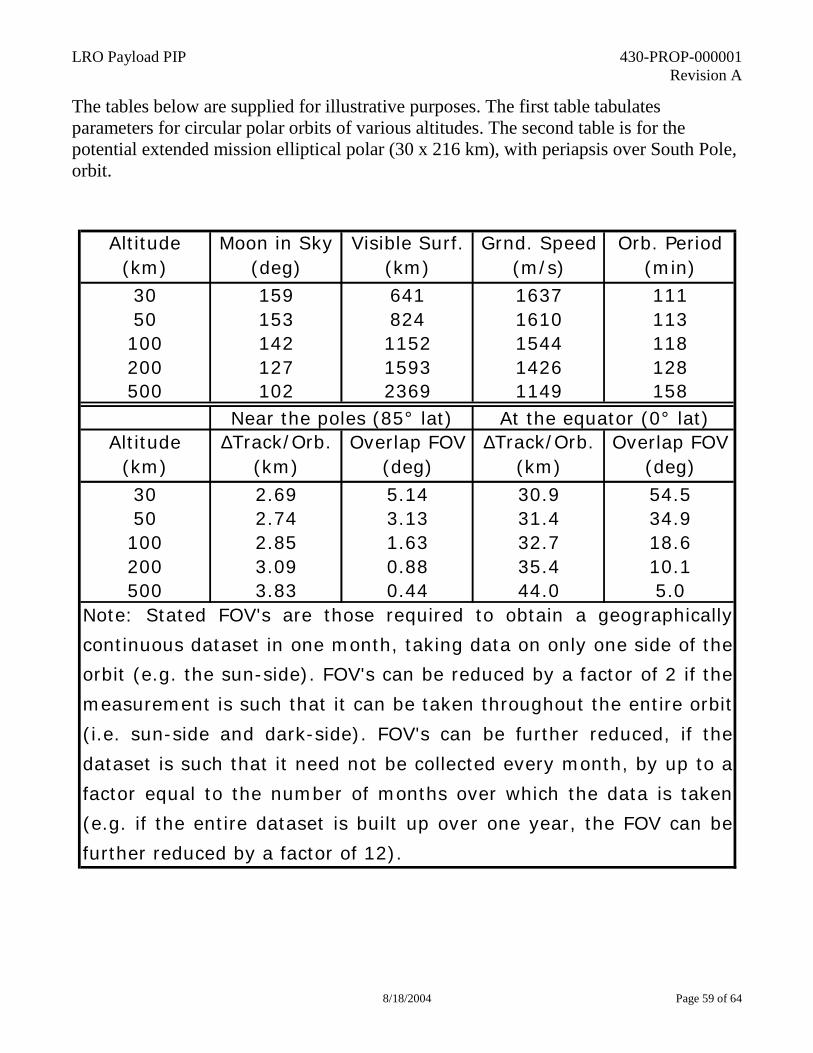
LRO Payload PIP 430-PROP-000001 Revision A
8/18/2004 Page 59 of 64
The tables below are supplied for illustrative purposes. The first table tabulates parameters for circular polar orbits of various altitudes. The second table is for the potential extended mission elliptical polar (30 x 216 km), with periapsis over South Pole, orbit.
Altitude Moon in Sky Visible Surf. Grnd. Speed Orb. Period(km) (deg) (km) (m/s) (min)30 159 641 1637 11150 153 824 1610 113100 142 1152 1544 118200 127 1593 1426 128500 102 2369 1149 158
Altitude ∆Track/Orb. Overlap FOV ∆Track/Orb. Overlap FOV(km) (km) (deg) (km) (deg)30 2.69 5.14 30.9 54.550 2.74 3.13 31.4 34.9100 2.85 1.63 32.7 18.6200 3.09 0.88 35.4 10.1500 3.83 0.44 44.0 5.0
Note: Stated FOV's are those required to obtain a geographically
continuous dataset in one month, taking data on only one side of the
orbit (e.g. the sun-side). FOV's can be reduced by a factor of 2 if the
measurement is such that it can be taken throughout the entire orbit
(i.e. sun-side and dark-side). FOV's can be further reduced, if the
dataset is such that it need not be collected every month, by up to a
factor equal to the number of months over which the data is taken
(e.g. if the entire dataset is built up over one year, the FOV can be
further reduced by a factor of 12).
Near the poles (85° lat) At the equator (0° lat)
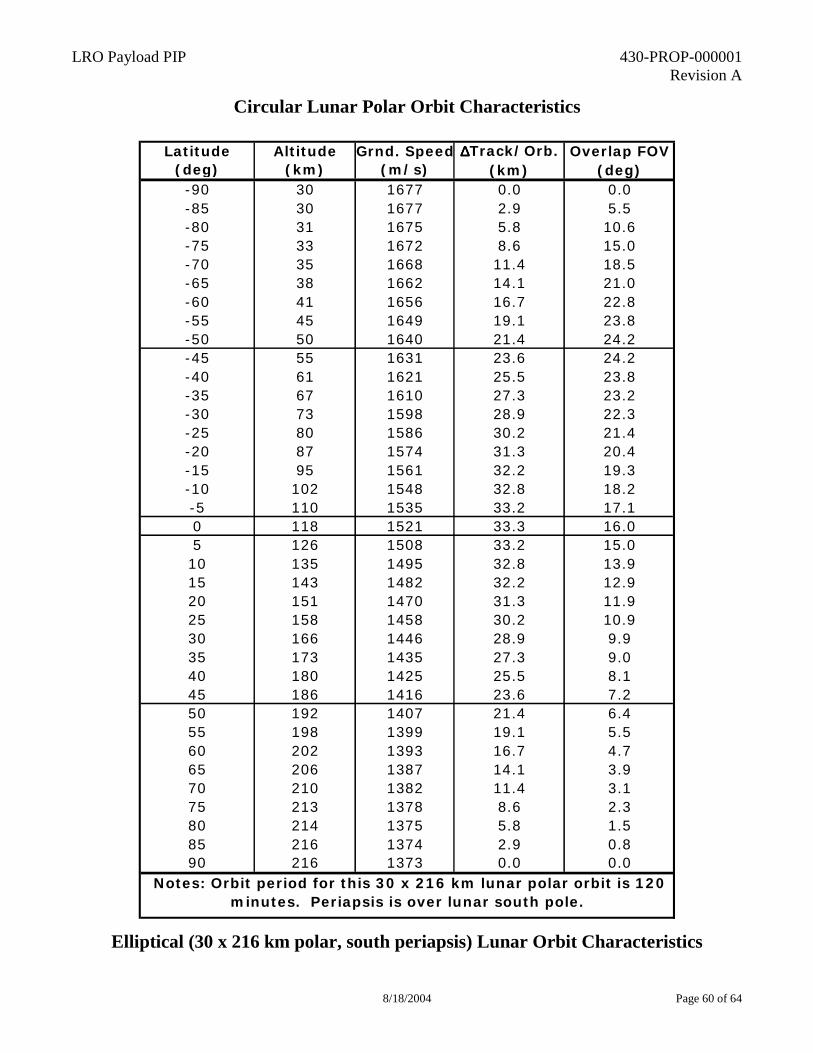
LRO Payload PIP 430-PROP-000001 Revision A
8/18/2004 Page 60 of 64
Circular Lunar Polar Orbit Characteristics
Elliptical (30 x 216 km polar, south periapsis) Lunar Orbit Characteristics
Latitude Altitude Grnd. Speed ∆∆∆∆Track/Orb. Overlap FOV(deg) (km) (m/s) (km) (deg)-90 30 1677 0.0 0.0-85 30 1677 2.9 5.5-80 31 1675 5.8 10.6-75 33 1672 8.6 15.0-70 35 1668 11.4 18.5-65 38 1662 14.1 21.0-60 41 1656 16.7 22.8-55 45 1649 19.1 23.8-50 50 1640 21.4 24.2-45 55 1631 23.6 24.2-40 61 1621 25.5 23.8-35 67 1610 27.3 23.2-30 73 1598 28.9 22.3-25 80 1586 30.2 21.4-20 87 1574 31.3 20.4-15 95 1561 32.2 19.3-10 102 1548 32.8 18.2-5 110 1535 33.2 17.10 118 1521 33.3 16.05 126 1508 33.2 15.010 135 1495 32.8 13.915 143 1482 32.2 12.920 151 1470 31.3 11.925 158 1458 30.2 10.930 166 1446 28.9 9.935 173 1435 27.3 9.040 180 1425 25.5 8.145 186 1416 23.6 7.250 192 1407 21.4 6.455 198 1399 19.1 5.560 202 1393 16.7 4.765 206 1387 14.1 3.970 210 1382 11.4 3.175 213 1378 8.6 2.380 214 1375 5.8 1.585 216 1374 2.9 0.890 216 1373 0.0 0.0
Notes: Orbit period for this 30 x 216 km lunar polar orbit is 120 minutes. Periapsis is over lunar south pole.
LRO Payload PIP 430-PROP-000001 Revision A
8/18/2004 Page 61 of 64
Appendix D
Acronyms
LRO Payload PIP 430-PROP-000001 Revision A
8/18/2004 Page 62 of 64
Acronym/
Abbreviation Definition
ASICs Application Specific Integrated Circuits C Celsius (˚C) C&DH Command & Data Handling C.G. Center of Gravity CAD Computer Aided Design CCSDS Consultative Committee on Space Data Standards CDR Critical Design Review CG Center of Gravity CLA Coupled Loads analysis CM Configuration Management CPL Capillary Pumped Loop dB Decibel deg Degree EIDP End Item Data Package EM Engineering Model F&PRD Functional & Performance Requirements Document FEM Finite Element Model FM Flight Model FMECA Failure Modes Effects and Criticality Analysis FS Factors of Safety g acceleration due to gravity Gb Gigabit GEVS-SE Goddard Environmental Verification Specification – Shuttle/ELV GN&C Guidance Navigation & Control grms Gravity root-mean-squared GSE Ground Support Equipment GSFC Goddard Space Flight Center Hz Hertz IAR Instrument Accommodation Review I-CDR Instrument Critical Design Review ICDs Interface Control Documents ID Identification IET Instrument Engineering Team IGSE Instrument Ground Support I-ORR Instrument Operational Readiness Review I-PDR Instrument Preliminary Design Review I-PSR Instrument Pre-Ship Review ISTs Instrument Support Team Kbps Kilobits per second kg kilogram lat latitude
LRO Payload PIP 430-PROP-000001 Revision A
8/18/2004 Page 63 of 64
Acronym/ Abbreviation
Definition
LHP Loop Heat Pipe m meter m/s meter/second MECO Main engine cut-off MET Mission Elapsed Time MGSE Mechanical Ground Support Equipment min minute MIUL Materials identification and usage lists MLI Multi-Layer Insulation MOR Mission Operations Review MOT Mission Operations Team MRT Mission Readiness Testing ms millisecond MS Margin of Safety MSC “trade name” MUA Material Usage Agreement N/A Not Applicable NASA National Aeronautics and Space Administration NASTRAN NASA Structural Analysis NSI NASA Standard Initiator OASPL Overall Sound Pressure Level ORR Operational Readiness Review Ps Probability of Success PAF Payload Attach Fitting PDR Preliminary Design Review PDS Planetary Data System PEMs Plastic Encapsulated Microcircuits PER Pre-Environmental Review PFR Problem/Failure anomaly report PI Principal Investigator PIs Principal Investigators PSA Parts Stress Analysis psi Pound per Square Inch PSR Pre-Ship Review PWB Printed Wiring Board QA Quality Assurance RMS Root-Mean-Square S/C Spacecraft S/W Software sec second SEE Single Event Effects SET Spacecraft Engineering Team
LRO Payload PIP 430-PROP-000001 Revision A
8/18/2004 Page 64 of 64
Acronym/ Abbreviation
Definition
SINDA “S/W trade name” SMEX Small Explorer SPC Single Part Constraint SRR System Requirements Review TBD To be determined TECO Third stage engine cut-off TMM Thermal Math Model TSS Thermal Synthesizer System V Volt VCHP Variable Conductance Heat Pipe W/m Watts/meter W/m2 Watts/meter squared µPa µPascal