Embed Size (px)
Citation preview

Robotic Augmentation
Of Human Locomotion
For High Speed Running
by
Jason Kerestes
A Thesis Presented in Partial Fulfillment of the Requirements for the Degree
Master of Science
Approved November 2014 by the Graduate Supervisory Committee:
Thomas Sugar, Chair
Sangram Redkar Bradley Rogers
ARIZONA STATE UNIVERSITY
December 2014

i
ABSTRACT
Human running requires extensive training and conditioning for an individual to
maintain high speeds (greater than 10mph) for an extended duration of time. Studies
have shown that running at peak speeds generates a high metabolic cost due to the use of
large muscle groups in the legs associated with the human gait cycle. Applying
supplemental external and internal forces to the human body during the gait cycle has
been shown to decrease the metabolic cost for walking, allowing individuals to carry
additional weight and walk further distances. Significant research has been conducted to
reduce the metabolic cost of walking, however, there are few if any documented studies
that focus specifically on reducing the metabolic cost associated with high speed running.
Three mechanical systems were designed to work in concert with the human user to
decrease metabolic cost and increase the range and speeds at which a human can run.
The methods of design require a focus on mathematical modeling, simulations,
and metabolic cost. Mathematical modeling and simulations are used to aid in the design
process of robotic systems and metabolic testing is regarded as the final analysis process
to determine the true effectiveness of robotic prototypes. Metabolic data, (VO2) is the
volumetric consumption of oxygen, per minute, per unit mass (ml/min/kg). Metabolic
testing consists of analyzing the oxygen consumption of a test subject while performing a
task naturally and then comparing that data with analyzed oxygen consumption of the
same task while using an assistive device.
Three devices were designed and tested to augment high speed running. The first
device, AirLegs V1, is a mostly aluminum exoskeleton with two pneumatic linear
actuators connecting from the lower back directly to the user's thighs, allowing the device

ii
to induce a torque on the leg by pushing and pulling on the user’s thigh during running.
The device also makes use of two smaller pneumatic linear actuators which drive cables
connecting to small lever arms at the back of the heel, inducing a torque at the ankles.
Device two, AirLegs V2, is also pneumatically powered but is considered to be a soft suit
version of the first device. It uses cables to interface the forces created by actuators
located vertically on the user's back. These cables then connect to the back of the user’s
knees resulting in greater flexibility and range of motion of the legs. Device three, a Jet
Pack, produces an external force against the user's torso to propel a user forward and
upward making it easier to run. Third party testing, pilot demonstrations and timed trials
have demonstrated that all three of the devices effectively reduce the metabolic cost of
running below that of natural running with no device.

iii
TABLE OF CONTENTS
Page
LIST OF TABLES ................................................................................................................... iv
LIST OF FIGURES .................................................................................................................. v
CHAPTER
1 INTRODUCTION ................ ...................................................................................... 1
1.1 Force Effects on Humans Running Over Ground ............................... 3
1.2 Requirements of Control Systems ....................................................... 5
1.3 History of Exoskeletons ....................................................................... 6
1.4 Objectives ............................................................................................. 9
1.5 Hypothesis .......................................................................................... 10
1.6 Thesis Outline .................................................................................... 11
2 GAIT EXPLORATION ............................................................................................. 12
2.1 Human Gait Cycle .............................................................................. 12
2.2 Pulling Forces Needed for Augmentation ......................................... 15
2.3 OpenSim Modeling ............................................................................ 22
3 CONTROLLER METHODOLOGY .......................................................................... 24
3.1 Phase Oscillator .................................................................................. 24
3.2 Phase Controller ................................................................................. 28
4 DESIGN OF RUNNING AUGMENTATION DEVICES ................. .................... 37
4.1 AirLegs V1 ......................................................................................... 38
4.2 AirLegs V2 ......................................................................................... 42
4.3 Jet Pack ............................................................................................... 44

iv
CHAPTER Page
5 DEVICE EXPERIMENTATION AND ANALYSIS .............................................. 48
5.1 Army Research Laboratory Third Party Testing of AirLegs V1 ...... 49
5.2 AirLegs V2 Testing............................................................................ 50
5.3 Jet Pack Testing ................................................................................. 52
6 CONCLUSIONS AND RECOMMENDATIONS ................................................. 55
REFERENCES....... ............................................................................................................... 58
APPENDIX
A JET PACK IRB PROTOCOL AND CONSENT DOCUMENTATION ............. 60
v
LIST OF TABLES
Table Page
5.1 Metabolic Cost When Running With Powered Hips on Treadmill at ARL ..... 50
5.2 Speed and Heart Rate With and Without Jet Pack ............................................ 55

vi
LIST OF FIGURES
Figure Page
1.1 Three Devices with Forces Shown in Red Arrows .................................... 3
1.2 Forces Acting on the Runner ...................................................................... 3
1.3 Propulsive Power Needed to Run Versus Braking Power ......................... 4
1.4 Metabolic Cost Versus Applied Horizontal Force ..................................... 5
1.5 Apparatus for Facilitating Walking, Running, and Jumping ..................... 7
1.6 Hardiman Designed by General Electric .................................................... 8
1.7 BLEEX Exoskeleton Designed by Berkeley Researchers ......................... 9
1.8 Devices Designed to Augment Human Running ..................................... 10
2.1 The Walking Gait Cycle ........................................................................... 13
2.2 The running gait cycle............................................................................... 13
2.3 Forces Acting on a Runner ....................................................................... 14
2.4 The Propulsive Power Needed to Run Versus the Breaking Power ........ 15
2.5 Testing Rig Attached to Electric Golf Cart .............................................. 16
2.6 Pull Force Testing with Golf Cart Rigging .............................................. 17
2.7 Pulling Test Subject While Recording Metabolic Pilot Data .................. 17
2.8 Speed Versus Pulling Force at 7mph ........................................................ 18
2.9 Speed Versus Pulling Force at 9mph ........................................................ 19
2.10 Speed Versus Pulling Force at 12mph ..................................................... 19
2.11 Greatest Reduction in Metabolic Cost from 25 Degree Angle ................ 20
2.12 Metabolic Cost Free Running Versus Towed Running ........................... 21
2.13 OpenSim 3D model of Muscular and Skeletal System............................ 22

vii
Figure Page
2.14 Muscle Activation Energy with and Without Towing/Thrust Force ...... 23
3.1 Phase Plot Definition ................................................................................ 25
3.2 System Position Oscillation ...................................................................... 26
3.3 Phase Plot Limit Cycle .............................................................................. 26
3.4 System Damps to Zero .............................................................................. 27
3.5 Phase Plot Position and Velocity Go to Zero ........................................... 27
3.6 Inverted Pendulum Oscillates Similar to Human Leg ............................. 29
3.7 System Natural Frequency ........................................................................ 29
3.8 Damping Torque Oscillations ................................................................... 30
3.9 Inverted Damping Torque ......................................................................... 31
3.10 Spring Torque Oscillations ....................................................................... 32
3.11 Rate Gyro Thigh Signal ............................................................................ 32
3.12 Phase Angle for Left and Right Leg ......................................................... 34
3.13 Phase Angel and Control Signal for Left and Right Leg ......................... 35
3.14 Phase Oscillator Control Software Written in Matlab ............................. 36
3.15 Digilent Cerebot MC7 Microcontroller .................................................... 36
4.1 AirLegs V1 Left Back and Right Views .................................................. 38
4.2 AirLegs V1 Hip Joint Assembly .............................................................. 39
4.3 Actuator Assembly Connected to Heel to Provide Torque at Ankle....... 40
4.4 AirLegs V1 Gait Cycle ............................................................................. 41
4.5 AirLegs V2 Left Back and Right Views .................................................. 42
4.6 Jet Pack Left Back and Right Views ........................................................ 44
viii
Figure Page
4.7 Jet Pack Back Pack Prototype ................................................................... 46
4.8 Jet Pack Hand Held Controller ................................................................. 47
4.9 Matlab Simulink Control Software for Jet Pack ...................................... 48
5.1 AirLegs V2 Metabolic Demonstration ..................................................... 51
5.2 Subject Testing Jet Pack on 1 Mile Course .............................................. 52
5.3 Speed on 1 Mile Test With and Without Jet Pack ................................... 53
5.4 Heart Rate on 1 Mile Test With and Without Jet Pack ............................ 54

1
CHAPTER 1 INTRODUCTION
There are many methods to increase the speed and duration for which humans can
travel. One common method for faster travel is through the use of wheeled vehicles,
however, there are times when it would be beneficial for a person’s natural ability to run
to be augmented. When compared to common apparatuses such as wheeled vehicles, the
human gait cycle allows for increased mobility where wheeled vehicles cannot travel due
to incompatible terrain such as narrow passages, rocky terrain, or stairs. Although
walking or running can allow for transportation of individuals through areas where
wheeled vehicles cannot go, the duration of transportation and speed is heavily
constrained by the physical capabilities of the human in question. Some individuals that
are required to run for long distances at elevated speeds include infantry soldiers, police
officers, fire fighters, and athletes.
Individuals that would benefit from exceeding their natural physical capabilities
are consistent with those that perform strenuous activities where physical performance
directly relates to their overall success. In cases regarding military infantry, soldiers are
often required to traverse long distances over rough terrain which can greatly impact their
success in the battlefield (Fletcher, 1974). A robotic exoskeleton which augments human
locomotion of the legs could increase a soldier's ability to accomplish strenuous missions,
preserve cardiovascular performance leading to improved decision making, reduce the
potential for injury due to over exertion, and enhance peak running speeds making a
soldier faster than their enemies. The improved characteristics of soldiers using
mechanical devices for augmentation could potentially result in the preservation of
2
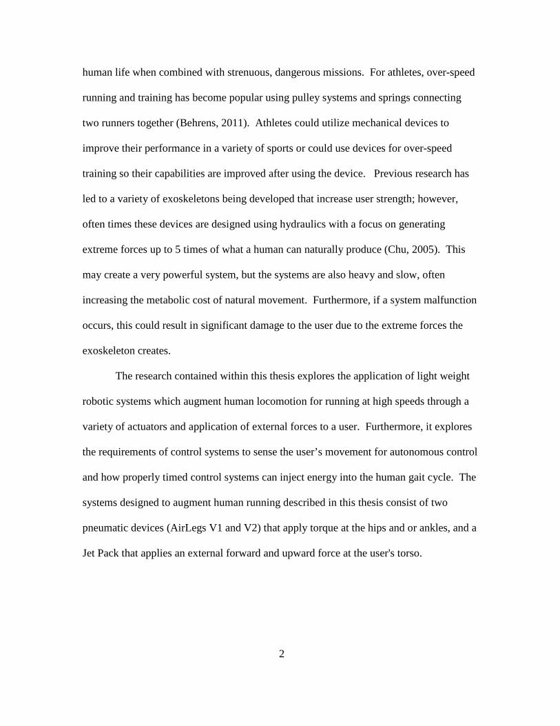
human life when combined with strenuous, dangerous missions. For athletes, over-speed
running and training has become popular using pulley systems and springs connecting
two runners together (Behrens, 2011). Athletes could utilize mechanical devices to
improve their performance in a variety of sports or could use devices for over-speed
training so their capabilities are improved after using the device. Previous research has
led to a variety of exoskeletons being developed that increase user strength; however,
often times these devices are designed using hydraulics with a focus on generating
extreme forces up to 5 times of what a human can naturally produce (Chu, 2005). This
may create a very powerful system, but the systems are also heavy and slow, often
increasing the metabolic cost of natural movement. Furthermore, if a system malfunction
occurs, this could result in significant damage to the user due to the extreme forces the
exoskeleton creates.
The research contained within this thesis explores the application of light weight
robotic systems which augment human locomotion for running at high speeds through a
variety of actuators and application of external forces to a user. Furthermore, it explores
the requirements of control systems to sense the user’s movement for autonomous control
and how properly timed control systems can inject energy into the human gait cycle. The
systems designed to augment human running described in this thesis consist of two
pneumatic devices (AirLegs V1 and V2) that apply torque at the hips and or ankles, and a
Jet Pack that applies an external forward and upward force at the user's torso.

3
Figure 1.1. Three Devices with Forces Shown in Red Arrows, From Left to Right; AirLegs V1, AirLegs V2, Jet Pack
1.1 Force Effects on Humans Running Over Ground
During the running gait cycle, the main external forces acting on the runner’s motion are air drag and rolling friction.
Figure 1.2. Forces Acting on the Runner
The external forces acting on a runner, coupled with supporting the mass of the runner,
are attributed to metabolic expenditure because the user’s musculoskeletal system must
overcome these forces to run at high speeds requiring significant amounts of oxygen.
Furthermore, the metabolic cost associated with running has been shown to increase as
relative running speeds increase (Gottschall, 2003). Three power curves based on the
4
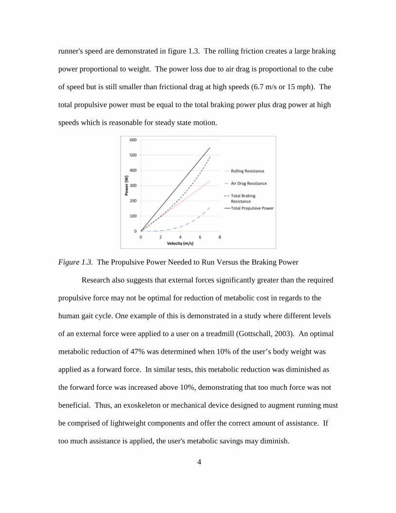
runner's speed are demonstrated in figure 1.3. The rolling friction creates a large braking
power proportional to weight. The power loss due to air drag is proportional to the cube
of speed but is still smaller than frictional drag at high speeds (6.7 m/s or 15 mph). The
total propulsive power must be equal to the total braking power plus drag power at high
speeds which is reasonable for steady state motion.
Figure 1.3. The Propulsive Power Needed to Run Versus the Braking Power
Research also suggests that external forces significantly greater than the required
propulsive force may not be optimal for reduction of metabolic cost in regards to the
human gait cycle. One example of this is demonstrated in a study where different levels
of an external force were applied to a user on a treadmill (Gottschall, 2003). An optimal
metabolic reduction of 47% was determined when 10% of the user’s body weight was
applied as a forward force. In similar tests, this metabolic reduction was diminished as
the forward force was increased above 10%, demonstrating that too much force was not
beneficial. Thus, an exoskeleton or mechanical device designed to augment running must
be comprised of lightweight components and offer the correct amount of assistance. If
too much assistance is applied, the user's metabolic savings may diminish.

5
Figure 1.4. Metabolic Cost Versus Applied Horizontal Force (Gottshall, 2003)
1.2 Requirements of control systems
To achieve autonomous control of a robotic exoskeleton, a control system must be
designed in a way that enables the device to operate in concert with its user. This can be
done by utilizing various sensors, switches, or user input (Ollinger, 2007). One problem
that is often encountered when developing a control system in which a robot is to
augment human locomotion is that if sensors are used to monitor limb movement, then
applying forces to that limb adds impedance. This can cause the control system to lose
stability because it is now manipulating its own input. Groups have attempted to address
this issue by means of adding inertia compensation for more precise control; however this
then leads to a delayed control system, especially if using force sensors that are not
mounted closely to the physical interface of the user (Zanotto, 2013). Another approach
to exoskeleton control is the use of a feed forward control system. Feed forward control
systems have been used to compensate for the effects of gravity on a user’s limbs but

6
these can quickly become unstable as well when coupled with the added inertia of an
exoskeleton component combined with the user’s limb. Furthermore, control systems
designed to function based on negative damping of the user's limb, coupled with feed
forward control and no inertia compensation, are likely to become unstable as well
(Zanotto, 2013). Although there is no known research regarding high speed running and
disturbances to the human body such as an exoskeleton becoming unstable or moving out
of sync with the user, it is easy to imagine that a poor control system would cause the
user to feel uncomfortable, especially with the risk of falling. It can also be assumed that
if an exoskeleton is not perfectly in sync with the human i.e. significantly delayed or
advanced actuators, the exoskeleton would not induce running augmentation because the
user would be working against the robot for a portion of the gait cycle (Ollinger, 2007).
1.3 History of Exoskeletons
The first recordings of exoskeleton type devices date back to the late 1800's when
Nicholas Yagn began building what he called an "Apparatus for facilitating walking,
running, and jumping" (Yagn, 1890). At the time, microprocessors had yet to be
developed to control the device which resulted in a mostly passive apparatus; however,
there were some pneumatic hand controls to activate artificial muscles.

7
Figure 1.5. Apparatus for Facilitating Walking, Running, and Jumping (Yagn, 1890)
From information contained in a patent filled on February 11th 1890, Yagn developed an
air powered device which was intended to utilize passive springs and cords to transfer
momentum of the torso into energy for moving the feet at a higher rate of speed while
carrying a load. Due to lack of documentation besides the patent which it was filed
under, the success of this device cannot be determined. It was not until the mid 1960's
that documentation of another exoskeleton device was published when General Electric
developed and tested an exoskeleton named Hardiman (General Electric, 1968).

8
Figure 1.6. Hardiman Designed by General Electric (General Electric, 1968)
The Hardiman device, a hydraulic full body exoskeleton, was designed to allow a
user to manipulate extremely heavy objects up to 250lbs and consisted of a master-slave
type approach to have the exoskeleton follow the movements of its pilot. Although they
created a full scale prototype, the Hardiman project was eventually abandoned because
the device was never capable of functioning properly due to weighing 1500lbs and
limitations in sensing and actuator technology. When tested, the Hardiman would
become violently out of control. Since the 1960's, advancements in technology have lead
to many improvements in not only sensors, but hardware as well. With the development
of the microprocessor in 1972 and continuous development thereafter, devices to assist
human locomotion became much more practical (Ceruzzi, 2003). Within the last 10
years, exoskeleton type devices have become much more prevalent with many
researchers developing their devices in conjunction with robotics. An example of an

9
exoskeleton using microprocessors and integrated sensors is the Berkeley Lower
Extremity Exoskeleton (BLEEX). BLEEX was developed in 2001 and connects to a
user’s back and legs.
Figure 1.7. BLEEX Exoskeleton Designed by Berkeley Researchers (Chu, 2005)
BLEEX applied torques to a user's hip, knee and ankle joints with hydraulic
actuators which were powered through an onboard combustion engine (Chu, 2005). The
device was designed to follow the user’s legs and support additional payload on the user's
back. Lack of success of the device was attributed to the use of hydraulic systems and
actuators that could not respond fast enough and the device was not effective for running.
1.4 Objective
The objective of this thesis is to present alternative methods for augmentation of
the human running gait through a variety of different robotic devices. Three devices have
been designed, built, and tested to determine the most effective method for adding energy

10
into the human gait cycle and thereby reducing the metabolic cost associated with
running at high speed.
Figure 1.8. Devices Designed to Augment Human Running. From Left to Right, AirLegs V1, AirLegs V2, and Jet Pack Furthermore, the devices described in this thesis were designed to be as simple as
possible to minimize the number of sensors and actuators required for operation while
still attempting to augment human locomotion.
1.5 Hypothesis
The general hypothesis for this research project is that by utilizing robotic
mechanisms that exert an appropriate magnitude of force at the right time, human
locomotion for running at high speed can be augmented, effectively reducing the
metabolic cost of running. Three methods for achieving human locomotion augmentation
were designed, built and tested. The specific hypotheses for this research is as follows:

11
• An exoskeleton device consisting of pneumatic actuators connected to the legs
and ankles will allow for running at high speeds while reducing the metabolic cost
of running.
• A soft-suit exoskeleton using cables connected to pneumatic actuators at the user's
back and knees will assist human locomotion and reduce metabolic cost for
running.
• A propulsive device at the user's back will assist human locomotion and reduce
the metabolic cost for running
1.6 Thesis Outline
The remaining sections of this thesis are devoted to the exploration of human
running gait, development of a phase controller, and development of devices which
augment human locomotion for high speed running. Chapter 2 presents a general
background on the human gait cycle and explores methods for determining the required
forces needed to enhance running. Chapter 3 describes the development of a phase
oscillator to control exoskeleton movement. Chapter 4 describes the design of the three
devices developed to augment human running. Chapter 5 presents methods for analytical
testing and determining the metabolic efficiency of the devices. Chapter 5 focuses on
reviewing the devices and conclusions.

12
CHAPTER 2
GAIT EXPLORATION
Chapter two explains the human gait cycle and background methodology for
analyzing necessary forces for running enhancement and the significant aspects of the
gait cycle are determined.
2.1 Human Gait Cycle
Humans, like most other bipedal animals, have the capability of walking by
alternating their legs in a particular fashion. Walking or running, although a complicated
procedure of movements, requires almost no conscious thought about individual muscle
actuation. For a lower limb robotic exoskeleton, each actuator must be independently
controlled in perfect time with its human pilot to keep the device from obstructing the
path of the user’s legs. The human gait cycle is commonly broken down into two main
phases; the stance phase, and the swing phase (Vaughn, 1992). The two phases
combined make up a common walking procedure starting at heel strike of one foot, and
continues until that same foot has left the ground and returns to its original orientation.
The stance phase begins when one foot first touches the ground known as a heel strike
and continues until push off. The swing phase then contains motions where that same
foot is in the air, until just before heel strike. The swing and stance phases contain
multiple orientations throughout their duration. For most individuals, general walking
and running gaits are largely uniform across a broad spectrum of people.

13
Figure 2.1. The Walking Gait Cycle (Donatelli, 1996). unshaded leg in stance phase and
shaded leg in swing phase.
According to the Gait Analysis Laboratory (Vaughn, 1992), the stance phase is
responsible for "first double support" which is when both feet are on the ground. It is also
responsible for "Single limb stance" where only one foot is making contact with the
ground and "second double support" where both feet are back on the ground. Although
similar, the average running gait for humans contains slight variations within the stance
and swing phase because at high speed, both feet never make contact with the ground at
the same time.
Figure 2.2. The Running Gait Cycle (Donatelli, 1996) ; unshaded leg in stance phase and
shaded leg in swing phase.
With regards to the running gait cycle, focusing only on the right (unshaded) leg in figure
2.2, it can be seen that propulsive forces originate during the stance phase when a runner
is pushing off the ground. During this time, the runner's leg is rotating clockwise,

14
utilizing a clockwise torque at the hip. The opposite (shaded) leg is in swing phase at the
same time and a counterclockwise torque is required to rotate the leg forward.
Because walking and running gaits are different which can be seen when comparing
figure 2.1 and figure 2.2, one critical component of a controller must be its capability to
transition from a walking gait to a running gait if it is to keep from inhibiting its user.
This poses a difficult problem for robotic systems that use a state based approach because
the robot must detect and recognize different gait cycle patterns. This concept is
explored further in Chapter 3.
During the running gait cycle, the main external forces acting on the runner’s
motion are air drag and rolling friction.
Figure 2.3. Forces Acting on the Runner
These forces, coupled with supporting the mass of the runner, are attributed to metabolic
expenditure because the user’s musculoskeletal system must overcome these forces to run
at high speeds. It can be determined by the common observer that propulsive forces for
natural running are only generated during the stance phase, while the feet are on the
ground. Thus, for a moment in the running gait cycle, there is no propulsive force being
generated while both feet are off the ground. Also, rolling resistance creates a large
braking power proportional to runner's weight which also only occurs during the stance
15
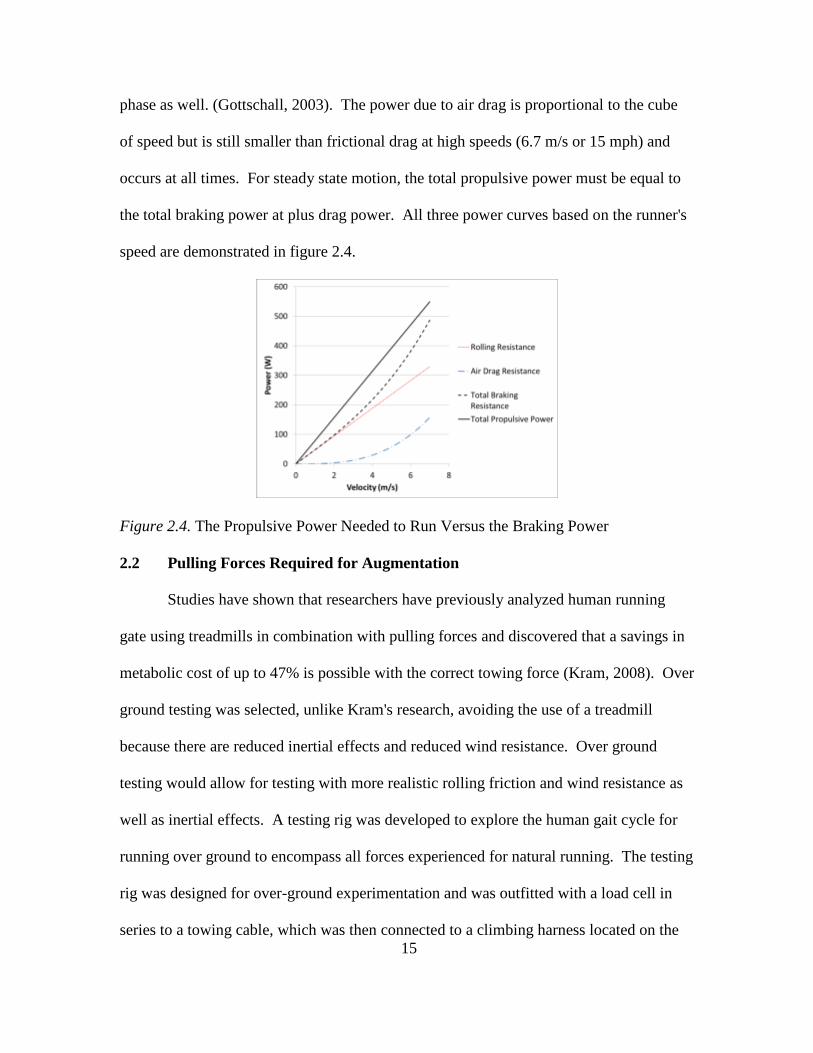
phase as well. (Gottschall, 2003). The power due to air drag is proportional to the cube
of speed but is still smaller than frictional drag at high speeds (6.7 m/s or 15 mph) and
occurs at all times. For steady state motion, the total propulsive power must be equal to
the total braking power at plus drag power. All three power curves based on the runner's
speed are demonstrated in figure 2.4.
Figure 2.4. The Propulsive Power Needed to Run Versus the Braking Power
2.2 Pulling Forces Required for Augmentation
Studies have shown that researchers have previously analyzed human running
gate using treadmills in combination with pulling forces and discovered that a savings in
metabolic cost of up to 47% is possible with the correct towing force (Kram, 2008). Over
ground testing was selected, unlike Kram's research, avoiding the use of a treadmill
because there are reduced inertial effects and reduced wind resistance. Over ground
testing would allow for testing with more realistic rolling friction and wind resistance as
well as inertial effects. A testing rig was developed to explore the human gait cycle for
running over ground to encompass all forces experienced for natural running. The testing
rig was designed for over-ground experimentation and was outfitted with a load cell in
series to a towing cable, which was then connected to a climbing harness located on the

16
pelvic area of a test subject. The testing rig was then attached to an electric golf cart to
impose towing forces on a runner. Two test variables were determined for this
experiment, towing force, and towing angle. Tests at different speeds were performed
with different towing angles to determine the most effective combination of towing force
and angle to produce the greatest metabolic reduction.
Figure 2.5. Testing Rig Attached to an Electric Golf Cart
Similar to Kram's research, where testing was conducted by adding towing forces on a
treadmill, experiments were created using the testing rig to determine what forces would
be necessary to reduce metabolic cost when running outdoors on an athletic track.
During the experiments, the runner wore a respirator like device to record metabolic data.
The load cell, in series with the towing cable, was used to determine the magnitude of
pulling force required to increase running speeds and reduce the metabolic cost a runner
experiences while running at high speeds.

17
Figure 2.6. Pull Force Testing with Golf Cart Rigging
Figure 2.7. Pulling Test Subject While Recording Metabolic Pilot Data
Various trials of assisted and unassisted runs were completed with tow angles
ranging from 5 degrees below horizontal to 35 degrees above horizontal. With each trial,
the golf cart was kept at a constant speed, allowing the test subject to determine the
appropriate amount of towing force based on what felt the best and how much force they
18
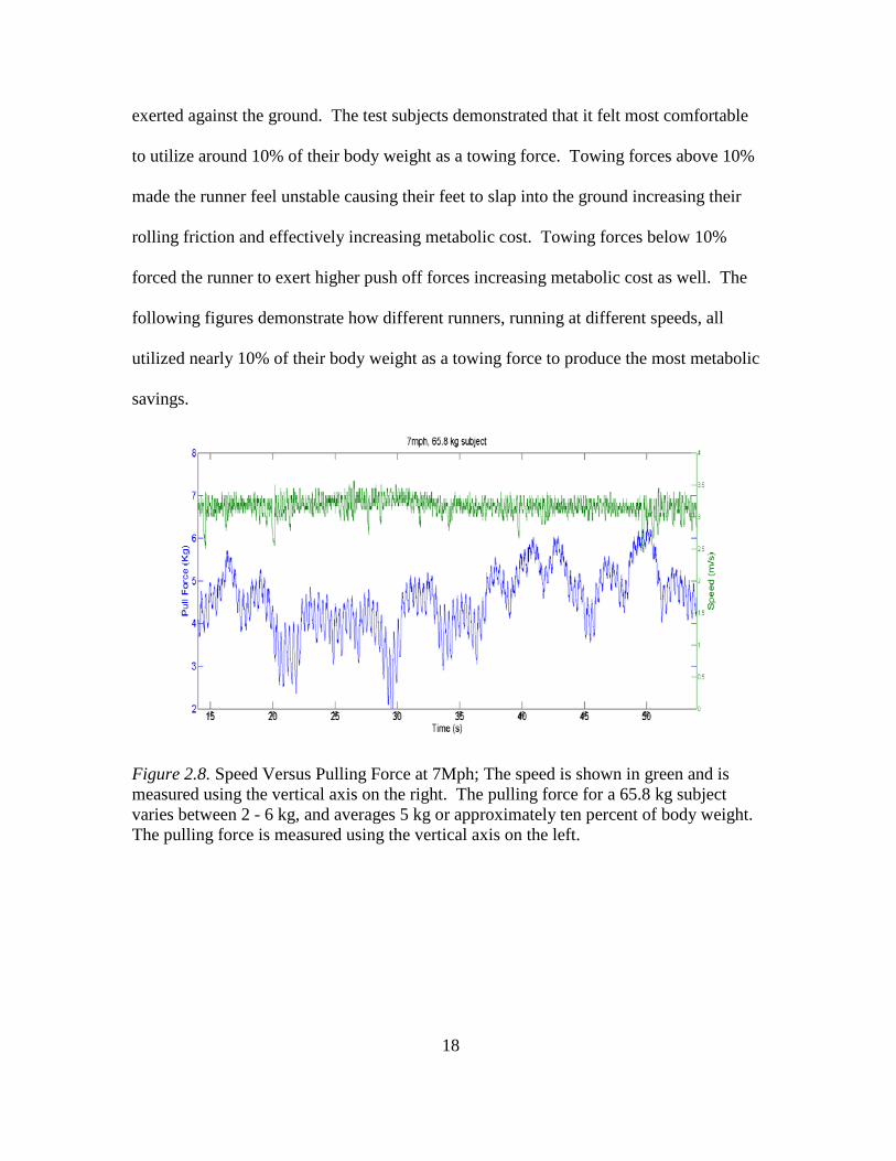
exerted against the ground. The test subjects demonstrated that it felt most comfortable
to utilize around 10% of their body weight as a towing force. Towing forces above 10%
made the runner feel unstable causing their feet to slap into the ground increasing their
rolling friction and effectively increasing metabolic cost. Towing forces below 10%
forced the runner to exert higher push off forces increasing metabolic cost as well. The
following figures demonstrate how different runners, running at different speeds, all
utilized nearly 10% of their body weight as a towing force to produce the most metabolic
savings.
Figure 2.8. Speed Versus Pulling Force at 7Mph; The speed is shown in green and is measured using the vertical axis on the right. The pulling force for a 65.8 kg subject varies between 2 - 6 kg, and averages 5 kg or approximately ten percent of body weight. The pulling force is measured using the vertical axis on the left.
19
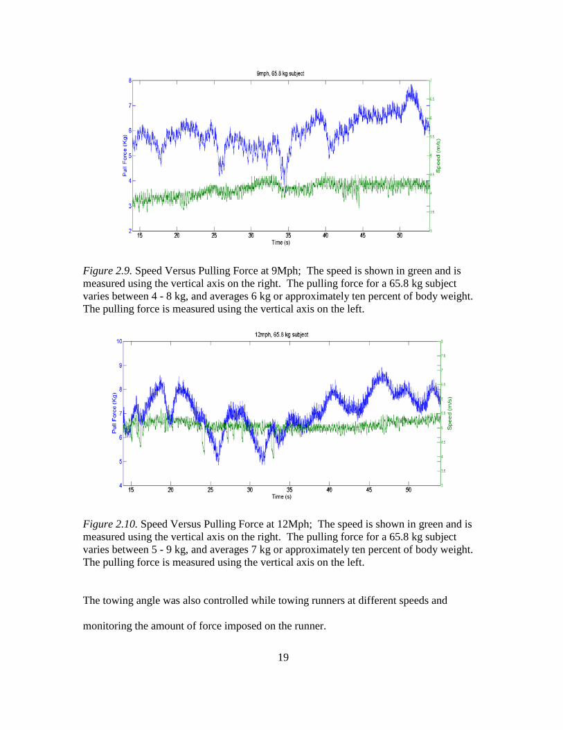
Figure 2.9. Speed Versus Pulling Force at 9Mph; The speed is shown in green and is measured using the vertical axis on the right. The pulling force for a 65.8 kg subject varies between 4 - 8 kg, and averages 6 kg or approximately ten percent of body weight. The pulling force is measured using the vertical axis on the left.
Figure 2.10. Speed Versus Pulling Force at 12Mph; The speed is shown in green and is measured using the vertical axis on the right. The pulling force for a 65.8 kg subject varies between 5 - 9 kg, and averages 7 kg or approximately ten percent of body weight. The pulling force is measured using the vertical axis on the left.
The towing angle was also controlled while towing runners at different speeds and
monitoring the amount of force imposed on the runner.

20
Testing showed that using around 10% of body weight as a towing force resulted in peak
metabolic savings and was a significant finding because the data was very similar to the
data recorded by the experimental tests performed by Kram (Kram, 2008). However,
unlike Kram's research, the metabolic savings for running over ground with a towing
force were closer to 30% savings. The metabolic cost is believed to be slightly off from
Kram's work because running over ground induces drag force. With experimental data
that validated Kram's research, it was clear that not only would a towing force help
runners on a treadmill, but over-ground as well. Peak metabolic reductions were
obtained when the towing angle was close to 25 degrees above horizontal resulting in a
reduction in metabolic cost of 29.8%.
Figure 2.11: Greatest Reduction in Metabolic Cost from 25 Degree Angle It was determined that the force should be angled at 25 degrees so that an upward force as
well as a propulsive force is generated. If the force was angled downward, the feet would
slap the ground adding discomfort and increasing the potential breaking force. Similar
to a runner carrying an additional payload or increasing their body weight, increased
breaking force is the result of increased rolling friction. A slight upward force acts
against the natural gravitational force, reducing ground reaction forces upon landing with

21
each foot. Kram's research on treadmills also concluded that both vertical (reducing the
runner’s potential mass) and horizontal (forward forces) made running easier (Kram,
2008). When both the optimal tow force of 10% of the user's body weight and a 25
degree angle towing force were used, significant metabolic reductions were exhibited. In
multiple trials over a 400 meter course, using data from 60 seconds of the test to 120
seconds, an average metabolic savings of 29.8% was recorded. Data points in the middle
of the test, 60 seconds - 120 seconds, were used because during this time span, the runner
and golf cart were traveling at a nearly constant pace. For times outside of this span, the
runner and golf cart were either speeding up or slowing down and acceleration of the
subjects and cart were not monitored.
Figure 2.12: Metabolic Cost Free Running Versus Towed Running The heart rate of the runners was also recorded during testing and was reduced as well
with an external horizontal/vertical force.
0 5
10 15 20 25 30 35 40
50 60 70 80 90 100 110 120 130
VO2
Seconds
Metabolic Cost 12mph Tow VS Free Run
Control No Pulling 12mph
Pulling 12mph

22
2.3 OpenSim Modeling of External Propulsive Force
A three dimensional model was created using Stanford's OpenSim software to
identify the specific muscle groups assisted with a towing force at 10% of a user's body
mass applied at an angle above horizontal.
Figure 2.13. OpenSim 3D Model of Muscular and Skeletal System
The model was imported from a running model created by Samuel Hamner and utilizes
kinematics from a subject running at similar speeds (Hamner, 2010). Additional forces
consistent with that of a towing force were simulated by manipulating the forces data file
manually prior to calculating inverse kinematics. Based on Hamner's research, the soleus
and gastrocnemius muscles are two of the muscles considered to be the "greatest
contributors to propulsion and support," (Hamner, 2010). The soleus and gastrocnemius
are located on the lower shank of the leg, commonly referred to as the calf muscle. It can
then be determined that because these muscles largely contribute to the propulsive force,
assisting them would yield the greatest metabolic reduction. The simulation validates
that a forward and upward force applied at the pelvis decreases the muscle activation
forces of the soleus and gastrocnemius muscles as seen in figure 2.14

23
Figure 2.14. Muscle Activation Energy With and Without Towing/Thrust Force.
However, unlike initial testing via tow rope and load cell, the simulation does not reflect
an optimal towing force to assist locomotion and implies that more towing force is better
without a limit to how much force is too much. The Stanford OpenSim software depicts
that adding an exponentially large towing force helps the leg muscles much more than
adding 10% of the runners mass because the software relies on input data from real test
subjects and cannot modify the trajectory of the model. The input data for OpenSim
includes marker data from a motion capture system and ground reaction forces acquired
from force plates during real experiments; thus, the output data produced by modifying
input files may have a small margin of error. Experiments performed with the golf cart
and towing rig showed that adding too great of a forward force made the runner feel
unstable with the sensation they were falling forward. The simulation does not model
this stability issue as the marker trajectory and force plate data cannot be modified
without performing new gait trails. Instead, the software places additional energy into
what is known as residuals, limiting the decrease of simulated muscle activation force.

24
CHAPTER 3
CONTROLLER METHODOLOGY
Control systems are needed to add energy and assist body motion in areas such as
powered orthotics, prosthetics, and exoskeletons (Hitt, 2007 and Wang, 2007). Systems
can add energy based on negative damping (Ollinger, 2007), patterns based on phase
angles (Holgate, 2008) and impedance control (Hogan, 1984). Using a phase angle
approach, a method was developed to add energy to assist human locomotion.
• The system adds a bounded amount of energy to create an oscillatory type
of motion.
• The control method has been shown to work on linear and rotary
mechanical systems
• A powered exoskeleton has been built and demonstrated using this new
control method.
3.1 Phase Oscillator
A phase-based approach is beneficial because the phase controller produces a
continuous forcing function that acts on a hybrid dynamic system. The phase approach
generates a continuous signal even though the dynamics of gait continuously change
because the forcing function does not change regardless of what a runner's legs are doing.
Phase plane analysis can be studied to determine if the system moves in a
repeating or limit cycle (Graham 1971). Use of a non-linear forcing function based on
the sine of the phase angle is beneficial because the sine function can never be greater or
smaller than one or negative one; the function is bounded. A standard, second order,

25
mechanical system equation is given: m represents the mass, b represents the damping, k
represents the stiffness.
𝑚�� + 𝑏�� + 𝑘𝑥 = 0 (1)
Groups have added negative damping to the system to force the system to move, but the
negative damping can become unstable because c�� grows as the velocity gets larger
(Ollinger, 2007).
𝑚�� + 𝑏�� + 𝑘𝑥 = 𝑐�� (2)
It was decided to add energy to the mechanical system by using a “phase oscillator” by
using the sine of the phase angle, φ. In figure 3.1, the phase angle, φ, is defined.
𝑚�� + 𝑏�� + 𝑘𝑥 = 𝑐 sin(∅) = 𝑐��√��2+𝑥2
(3)
If c is positive, the system oscillates back and forth. The energy is always bounded
because the forcing function must be between plus or minus c, see figures 3.2 and 3.3.
If c is negative, the energy is damped, and the system state goes to zero, see figures 3.4
and 3.5.
Figure 3.1. Phase Plot Definition; horizontal axis is the position, x, and the vertical axis is the velocity, ��. The sine of the phase angle phi is given by the opposite over the hypotenuse. The hypotenuse is given by √x2 + x2
26
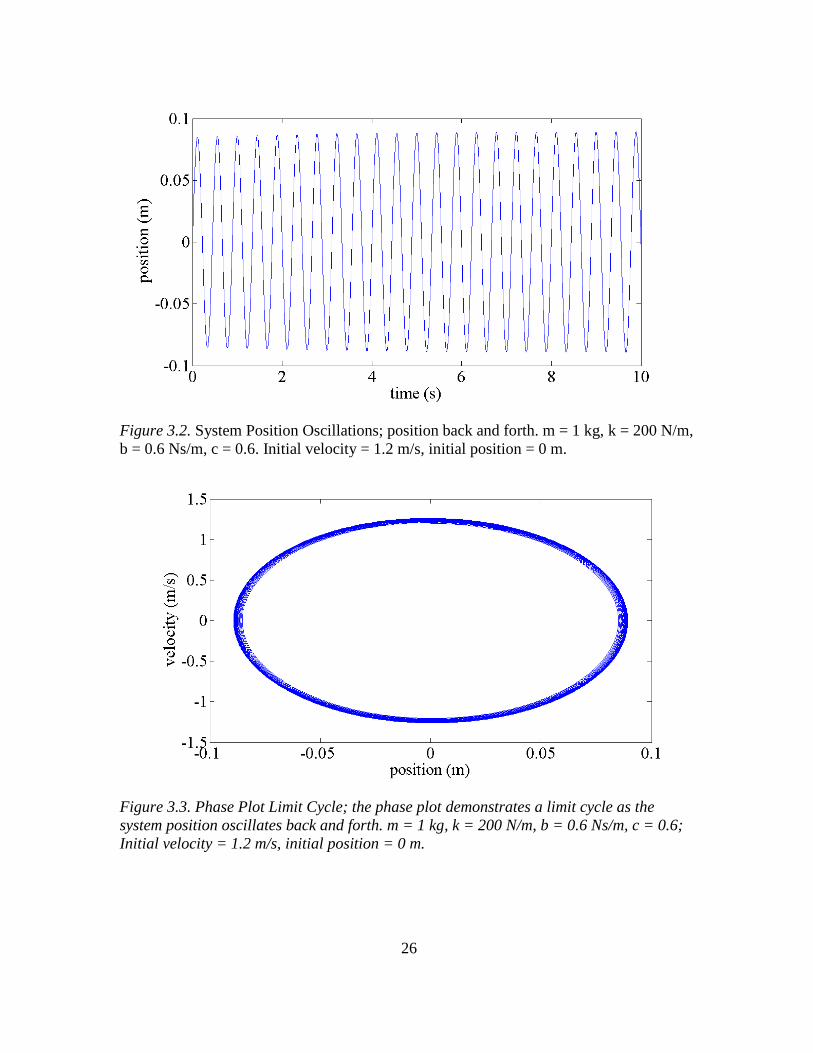
Figure 3.2. System Position Oscillations; position back and forth. m = 1 kg, k = 200 N/m, b = 0.6 Ns/m, c = 0.6. Initial velocity = 1.2 m/s, initial position = 0 m.
Figure 3.3. Phase Plot Limit Cycle; the phase plot demonstrates a limit cycle as the system position oscillates back and forth. m = 1 kg, k = 200 N/m, b = 0.6 Ns/m, c = 0.6; Initial velocity = 1.2 m/s, initial position = 0 m.

27
Figure 3.4. System Damps to Zero. m = 1 kg, k = 200 N/m; b = 0.6 Ns/m, c = -0.6. Initial velocity = 4 m/s, initial position = 0 m.
Figure 3.5. Phase Plot Position and Velocity Go to Zero; m = 1 kg, k = 200 N/m, b = 0.6 Ns/m, c = -0.6. Initial velocity = 4 m/s, initial position = 0 m. The analysis can be repeated for a rotational model: I represents the inertia, b represents
the damping, k represents the rotational stiffness.
𝐼�� + 𝑏�� + 𝑘𝜃 = 0 (4)

28
Again, energy was added to the mechanical system by using a phase oscillator by using
the sine of the phase angle, phi. Other trigonometric functions were studied as well to
determine their effectiveness, but sine of the phase angle achieved the best results.
𝐼�� + 𝑏�� + 𝑘𝜃 = 𝑐 sin(∅) = 𝑐�����2+𝜃2
(5)
If c is positive, the system oscillates back and forth. The energy is always bounded
because as �� gets bigger, in the limit the numerator and denominator cancel and just
equal c. If c is negative, the energy is damped out and the system state goes to zero.
3.2 Phase Controller
A testing device was designed where a small flywheel accelerates and decelerates,
creating inertial torque, causing a 1 meter pendulum with 3.4 kg at the end to oscillate
easily via parametric excitation similar to a small child pumping a swing, see figure 3.6.
The testing device demonstrates that a small torque can add energy to the relatively large
angular velocity of a pendulum. In an inverted pendulum, when c is set to negative, a
small inertia can accelerate and decelerate creating toques that dampen movement of the
pendulum. If the pendulum is swinging when the motor is turned on and c is negative, its
movements are quickly stopped. If the pendulum is placed in an inverted position, the
controller can keep the pendulum vertically upward like a well balanced inverted
pendulum.
29
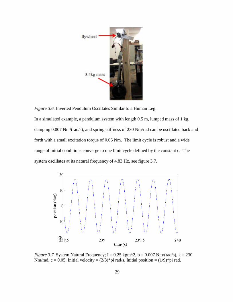
Figure 3.6. Inverted Pendulum Oscillates Similar to a Human Leg.
In a simulated example, a pendulum system with length 0.5 m, lumped mass of 1 kg,
damping 0.007 Nm/(rad/s), and spring stiffness of 230 Nm/rad can be oscillated back and
forth with a small excitation torque of 0.05 Nm. The limit cycle is robust and a wide
range of initial conditions converge to one limit cycle defined by the constant c. The
system oscillates at its natural frequency of 4.83 Hz, see figure 3.7.
Figure 3.7. System Natural Frequency; I = 0.25 kgm^2, b = 0.007 Nm/(rad/s), k = 230 Nm/rad, c = 0.05, Initial velocity = (2/3)*pi rad/s, Initial position = (1/9)*pi rad.
30
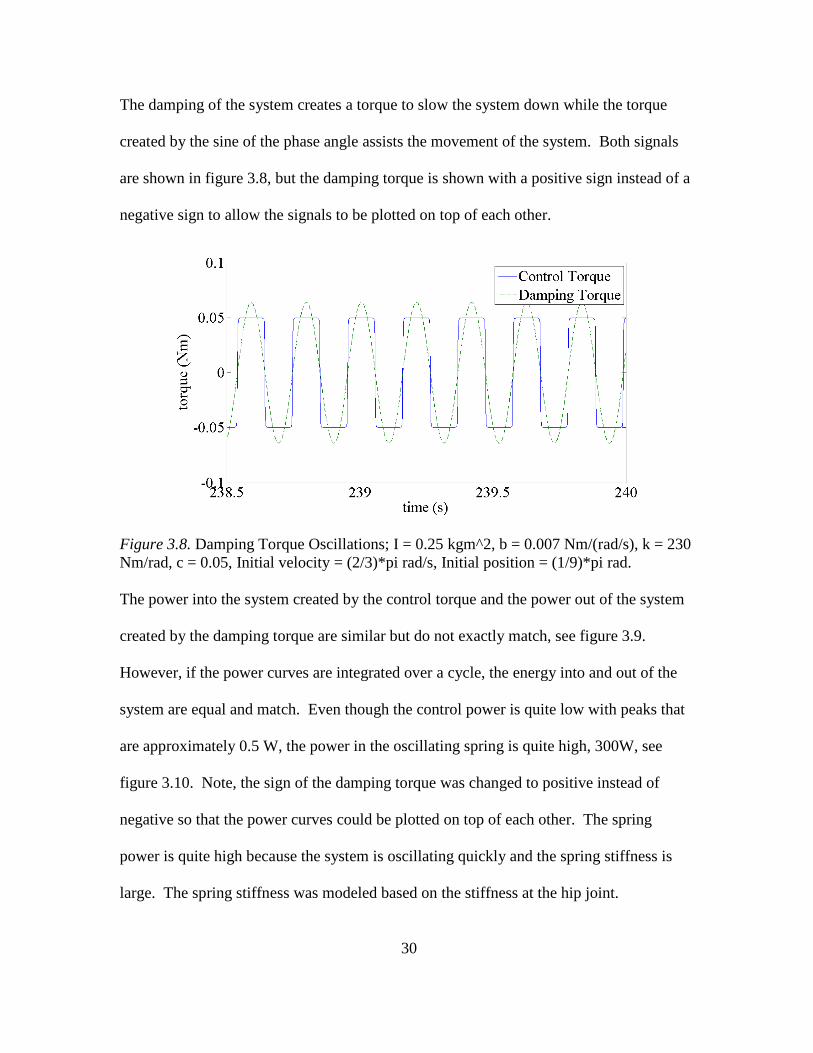
The damping of the system creates a torque to slow the system down while the torque
created by the sine of the phase angle assists the movement of the system. Both signals
are shown in figure 3.8, but the damping torque is shown with a positive sign instead of a
negative sign to allow the signals to be plotted on top of each other.
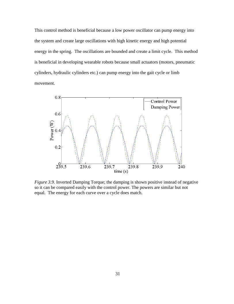
Figure 3.8. Damping Torque Oscillations; I = 0.25 kgm^2, b = 0.007 Nm/(rad/s), k = 230 Nm/rad, c = 0.05, Initial velocity = (2/3)*pi rad/s, Initial position = (1/9)*pi rad. The power into the system created by the control torque and the power out of the system
created by the damping torque are similar but do not exactly match, see figure 3.9.
However, if the power curves are integrated over a cycle, the energy into and out of the
system are equal and match. Even though the control power is quite low with peaks that
are approximately 0.5 W, the power in the oscillating spring is quite high, 300W, see
figure 3.10. Note, the sign of the damping torque was changed to positive instead of
negative so that the power curves could be plotted on top of each other. The spring
power is quite high because the system is oscillating quickly and the spring stiffness is
large. The spring stiffness was modeled based on the stiffness at the hip joint.
31
This control method is beneficial because a low power oscillator can pump energy into
the system and create large oscillations with high kinetic energy and high potential
energy in the spring. The oscillations are bounded and create a limit cycle. This method
is beneficial in developing wearable robots because small actuators (motors, pneumatic
cylinders, hydraulic cylinders etc.) can pump energy into the gait cycle or limb
movement.
Figure 3.9. Inverted Damping Torque; the damping is shown positive instead of negative so it can be compared easily with the control power. The powers are similar but not equal. The energy for each curve over a cycle does match.

32
Figure 3.10. Spring torque Oscillations; the system is oscillating back and forth quickly and the spring torque is high resulting in large power oscillations in the spring. Following the example of a torque applied to a pendulum structure based on the sine of
the phase angle, torque is applied to help the legs oscillate while walking and running by
applying a torque at the hips based on a phase oscillator. The leg of the human body can
be assumed to be a pendulum-like structure with inertia, damping, and a spring stiffness
(Blickhan, 1989). To enhance the pendulum motion, a parametric excitation torque can
be added (Seyfarth, 2002). The direction of the torque must be switched at the correct
timing and frequency and should be tuned with the frequency of gait. A phase oscillating
term based on the phase portrait determines the desired torque to add positive power to
the system.
AirLegs was designed and built to enhance walking and running using the phase
angle approach. The control torque signal is used to trigger pneumatic valves to create
torque at each hip joint which assists flexion and extension of the thigh. The pneumatic
cylinder pulls and pushes on the thigh plate attached to the leg. The linear force of the
cylinder creates an assistive torque at the hip joint.
33
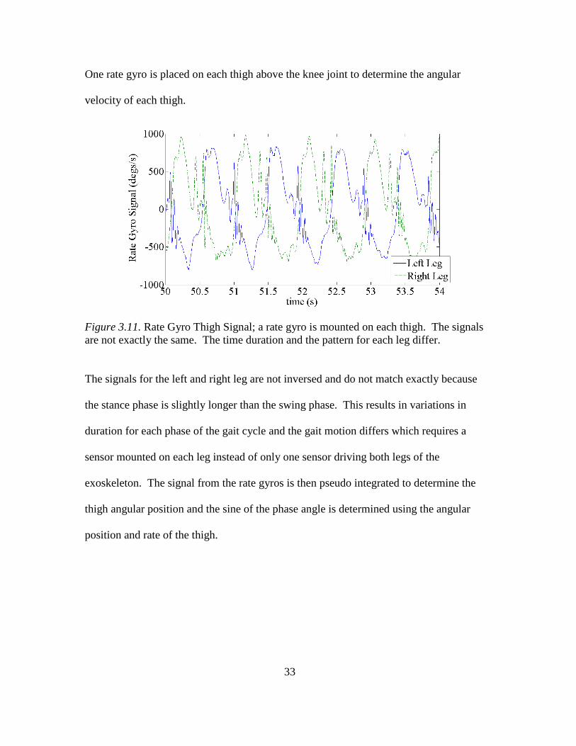
One rate gyro is placed on each thigh above the knee joint to determine the angular
velocity of each thigh.
Figure 3.11. Rate Gyro Thigh Signal; a rate gyro is mounted on each thigh. The signals are not exactly the same. The time duration and the pattern for each leg differ.
The signals for the left and right leg are not inversed and do not match exactly because
the stance phase is slightly longer than the swing phase. This results in variations in
duration for each phase of the gait cycle and the gait motion differs which requires a
sensor mounted on each leg instead of only one sensor driving both legs of the
exoskeleton. The signal from the rate gyros is then pseudo integrated to determine the
thigh angular position and the sine of the phase angle is determined using the angular
position and rate of the thigh.

34
Figure 3.12. Phase Angle for Left and Right Leg; the signal is calculated 500 times per second in the microprocessor. The left and right control signals are shown in dashed lines. As the leg swings forward, the control signal turns high, 100. As the leg swings backward, the control signal turns low, 0. Demonstration data with someone jogging on the treadmill is shown. The stance and
swing phase angles are periodic but are not exactly the same. The time that the right leg
swings forward is slightly larger than the time the same leg to swing backward. As the
leg waits for heel contact, the phase angle oscillates up and down for a brief 200-300 ms.
The control signal in Figure 3.12 is used to trigger a two-position, four-way valve.
When the control signal is high, the valve is energized and the thigh is pushed forward.
When the control signal is low, the spring inside the valve moves it into the second
position to pull the leg back. Even on a treadmill, the gait motion is not perfectly the
same. The time duration between the high signals for the left and right leg slightly
change. Each leg’s movement is slightly different.

35
Figure 3.13. Phase Angle and Control Signal for Left and Right Leg; The left and right control signals are shown in dashed lines. Using the phase controller, the exoskeleton can seamlessly assist walking,
running, and can transition from walking to running and back to walking without any
user input other than the user changing between walking and running. The seamless
transitions are possible because a continuous control signal is generated and used as a
triggering mechanism at 500Hz.
Implementation of the phase controller was accomplished using Matlab's
Simulink environment and a DSPic programming add-on to program a microprocessor.

36
Figure 3.14. Phase Oscillator Control Software Written in Matlab
Figure 3.14 shows the basic logic of the control software with two analog inputs on the
left hand side which are the sources of the rate gyros mounted on each leg. The analog
values from the rate gyros are then manipulated to control the exoskeleton.
The microcontroller chosen to run the control software is Microchip's
DSPic33FJ128MC710 which was available with Digilent's Cerebot MC7 breakout board.
The Cerebot MC7 was selected because it comes standard with two H-bridge motor
drivers which are used to control the pneumatic valves of the device.
Figure 3.15. A Digilent Cerebot MC7
37
CHAPTER 4
DESIGN OF RUNNING AUGMENTATION DEVICES
The design of a running augmentation device plays a critical role in the
effectiveness of the device. Robotic systems that are overly complicated with many
sensors and actuators can become cumbersome for the user, complicated for the
developer, and more susceptible to failure because there are more components that can
experience issues. The devices discussed in this thesis were designed focusing on four
main objectives;
• The device should be safe for the user to wear, even in the event of a
malfunction
• The device should utilize as few sensors and actuators as possible and the design
should be minimalistic in nature to reduce weight
• The device should be autonomous, requiring no continuous input from the user
except for their natural movement
• The device should be compatible with the average user and be capable of
performing on different users with little to no modification
Many other researchers have taken a different approach to designing exoskeletons
and assistive devices by designing very complex systems. Commonly, exoskeletons
contain a plethora of sensors with the goal of having the robot interpret every possible
scenario similar to Berkely's BLEEX (Chu, 2005). Many of these devices are also
designed with a great deal of actuators to assist many unnecessary motions and further
still, devices are often designed with focus on precise motion control. The primary
problem with these designs is that they have components and system architecture that is

38
not beneficial for their purpose. Extra sensors make the software and control algorithms
extremely complicated and designing a robot to interpret different scenarios becomes
very difficult because there are countless new scenarios that the developer cannot foresee.
Similarly, devices with a complex mechanical design consisting of many actuators are
more likely to restrict natural movement and weigh more because they require more
components. Devices that utilize precise motion control also increase in complexity and
require additional sensors with feedback actuators.
4.1 AirLegs V1
Figure 4.1. AirLegs V1 Left, Back, and Right Views; A pneumatic exoskeleton with actuators connecting directly to the user's thighs with artificial tendons connecting at the ankles.

39
In an effort to keep the running augmentation devices as simple as possible, the
results of the experiments with the golf cart tow testing and OpenSim simulations were
studied and AirLegs V1 was developed to only assist the muscles responsible for
maintaining high speed running. This is accomplished by adding torque to the hip and
ankle joints at precisely the right time.
The design of the AirLegs V1 exoskeleton was derived from studying the motion
of the gait cycle and the trajectories of the legs while running. A novel hip joint was
designed to allow flexibility in torso orientation. Often, when switching from walking to
running, users change the angle of their torso relative to the ground. The novel hip joint
allows for an extra partial degree of freedom by allowing approximately 15 degrees of
rotation.
Figure 4.2. Hip Joint Assembly
The hip joint allows for a user to either walk upright or run slightly bent over which is
more comfortable based on user feedback and video analysis of subjects transitioning
from walking to running without the device.

40
Ankle support was also incorporated into the design of AirLegs V1 by creating an
additional actuator mounted on the thigh plates. The purpose of assisting the rotational
torque of the ankle was incorporated because the ankle is rotated naturally for push off by
the soleus and gastrocnemius muscles which were discovered to generate most of the
forces for push off. The additional small actuators mounted on the thigh plates are
connected to a lever arm on the back of the user’s shoes resulting in a bi-articular spring
that is triggered similarly to the actuators at the hips. Figure 4.3 shows the small actuator
of one leg connected to elastic cords which are then attached to a lever arm on the back of
the heel.
Figure 4.3. Actuator Assembly Connected to Heel to Provide Torque at the Ankle
AirLegs V1 is powered by both battery and compressed air, using batteries to
control the pneumatic valves while compressed air powers the cylinders. A pneumatic
system was designed because preliminary analysis of motors available showed that a
motor capable of producing the necessary torques was not only heavy, but had difficulty

41
in changing direction fast enough to keep up with the oscillations of the human leg.
While there are motors capable of such speeds, they are heavy and draw a significant
amount of power to overcome high inertias associated with oscillations.
A carbon fiber storage tank is mounted on the device and stores compressed air at
4,500 psi. The compressed air is then regulated down to 800psi from a regulator built
into the tank. The air supply is then reduced again by an inline regulator to 90 psi which
is fed to the cylinders actuating the artificial tendons adding torque to the ankles. Further
reduction of pressure is accomplished by another inline actuator which reduces pressure
to 40 psi and is fed to the hip actuators. By utilizing light weight aluminum pneumatic
air cylinders, the total system weight is only 13.9 lbs.
FIGURE4.4. AirLegs V1 Gait Cycle; from left to right, top to bottom, the device pulls the left leg back during the stance phase and applies torque at the ankle during push off. The device then pushes the leg forward during the swing phase.
42
A significant benefit of mechanics incorporated in AirLegs V1 is that it pushes
the user's leg forward during the swing phase. This helps the user to accelerate their leg
forward in a faster manner which can be beneficial when running at high speeds to
overcome the inertia of the leg after push off.
4.2 AirLegs V2
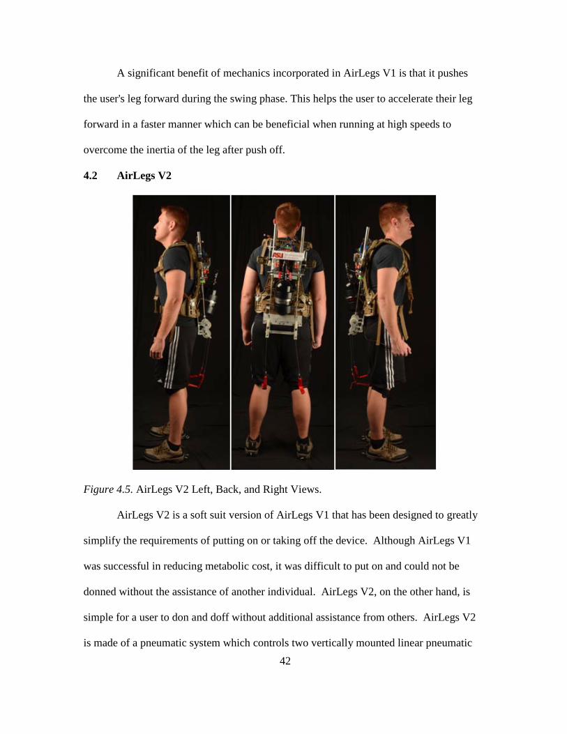
Figure 4.5. AirLegs V2 Left, Back, and Right Views.
AirLegs V2 is a soft suit version of AirLegs V1 that has been designed to greatly
simplify the requirements of putting on or taking off the device. Although AirLegs V1
was successful in reducing metabolic cost, it was difficult to put on and could not be
donned without the assistance of another individual. AirLegs V2, on the other hand, is
simple for a user to don and doff without additional assistance from others. AirLegs V2
is made of a pneumatic system which controls two vertically mounted linear pneumatic

43
cylinders attached behind the shoulder blades which are attached to a cable and pulley
system mounted on the user's back. The cables are then routed through a pulley system
to create a torque at the hips similar to that of AirLegs V1 but attach to two easily
removable Velcro knee braces. Limitations of the cable design result in forces only
pulling at the back of the thighs because a pushing force cannot be made from flexible
cable. The torque is applied to the hips during the stance phase increasing the ground
reaction forces created during push off.
A carbon fiber storage tank is mounted on the device and stores compressed air at
4,500 psi. The compressed air is then regulated down to 800psi from a regulator built
into the tank. The air supply is then reduced again by an inline regulator to 40 psi which
is fed to the cylinders actuating the cables that pull on the knee braces. Compared to
AirLegs V1, AirLegs V2 offers a greater range of motion, reduced overall weight, and it
easy to don and doff. AirLegs V2 is also much simpler to adjust for other users and
adjustment from one user to the next only requires lengthening or shortening of the
connecting straps that connect to the knee braces. The straps connected to the pulley
system are then attached to the knee braces by means of a plastic connector that can be
clipped or unclipped using one hand.
The soft suit design uses the same phase controller with only slight modifications
because it does not include ankle support. The phase controller allows for seamless
transition from walking to running and back to walking without any user input. AirLegs
V2 is also lighter than AirLegs V1 by 2.3lbs weighing in at 11.6lbs

44
4.3 Jet Pack
Figure 4.6. Jet Pack Left, Back, and Right Views; the prototype is worn like a common backpack and exhibits a forward and upward external force on the user’s torso.
The Jet Pack system was designed as an alternative method to enhance running
gait and utilizes two statically mounted high speed ducted fans. Benefits of the Jet Pack
when compared to the other devices includes; no adjustment necessary when switching
between users and no limitations on size of the potential user. Because there are no
components that attach to a users joints or limbs, no adjustments are necessary.
The Jet Pack's thrust is created by two ducted fans made of high speed brushless
motors (67,500 RPM) with 12 blades each. The ducted fans operate on 25 volt, 6 cell
lithium polymer batteries. Each brushless motor has its own battery and draws
approximately 100 amps from a brushless speed controller at peak thrust levels, resulting
in roughly 4 minutes of continuous use before depleting the battery to 22 volts. The
amount of thrust can be controlled by the user and the total run time increases if less than

45
100% thrust is used. The fans are mounted onto a military pack frame at an angle so that
the forces they produce are near 25 degrees below and behind the runner. By exerting
force which pushes the runner from below and behind the runner, forces similar to those
induced by the golf cart testing rig are recreated in a small light weight package with no
mechanical interaction between the device and user's legs.
Analysis of user height determined that while different users may be taller or
shorter, the most effective positioning of the fans created a force axially in line through
the runner's center of mass. In other words, the thrust vector needed to be in line with the
user's center of mass, on average just below their belly button. If the thrust force was too
high on the user's back, they felt as if they were going to tip forward. After lowering the
fans to a position which was closer to the center of mass of one user it was found that
they no longer had this feeling. To explore the positioning of the fans further, multiple
users each put on the device and found even though they all were of different height, the
relative offset of the fans to their center of mass was negligible between users. Because of
this relationship, the need for having the user control the height of the fans on their back
while running was not significant enough to add that feature into the controller and it
could be left as a static adjustment.
Analysis of the thrust angle was also conducted to determine if a controller should
include the ability to adjust the angle of the fans while running. It was found that the
thrust angle relative to horizontal was not only dependent on the angle between the fans
and the pack frame, but also the angle of the user's torso while running. For example, a
user that runs with their body more tipped forward would yield a higher forward thrust

46
than vertical thrust. Inversely, a user that ran with their torso angle closer to vertical
would produce a greater vertical thrust than horizontal.
Figure 4.7. Jet Pack Back Pack Prototype
The Jet Pack system also incorporates a hand held controller, see figure 3.7,
allowing the runner to dynamically change the magnitude of thrust produced. This
allows the runner to "tune" the Jet Pack so the force produced is closer to their 10% body
weight and feels good to the runner. The hand held controller allows the runner the
ability to not only control the amount of thrust produced, but also control on/off operation
of the ducted fans.

47
Figure 4.8. Jet Pack Hand Held Controller
In order for the hand controller to be capable of trust modulation, an onboard
microcontroller was programmed to handle user input. The microcontroller was
programed in C code generated by Matlab Simulink software that utilizes a visual
interface for programming similar to the methods for programming AirLegs. The
microcontroller operates by creating a pulse width digital modulated signal that can then
be interpreted by the onboard motor controllers. When the processor is initially turned on,
the thrust setting is at 50%. When the user squeezes the trigger, the fans turn on to the
desired speed. By pressing up or down on the controller hat, the thrust setting is increased
or decreased, producing more or less thrust.
48
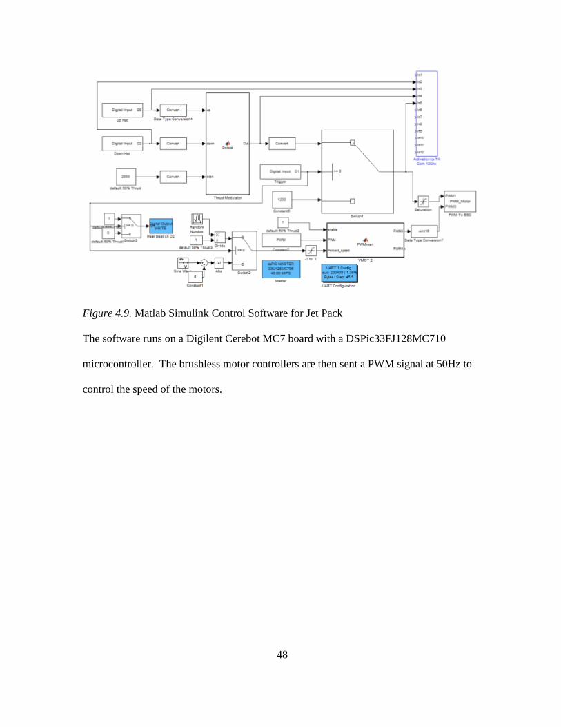
Figure 4.9. Matlab Simulink Control Software for Jet Pack
The software runs on a Digilent Cerebot MC7 board with a DSPic33FJ128MC710
microcontroller. The brushless motor controllers are then sent a PWM signal at 50Hz to
control the speed of the motors.

49
Chapter 5
DEVICE EXPERIMENTATION AND ANALYSIS
In chapter 5, the experimental process and data analysis are discussed for each
device. Due to the complexity of IRB protocol, not all devices have been approved for
human subject testing at the time of this document and have only been demoed at this
time. Testing has been concluded for the Jet Pack and AirLegs V1 has been tested by the
Army Research Laboratories.
5.1 Army Research Laboratory Third Party Testing of AirLegs V1
At the Army Research Laboratory, AirLegs V1 was tested on two subjects with
hip actuators only. The users were strapped into the device and wore a chest pack
metabolic unit after placing reflective markers on reference points on their body. A
motion tracking system was used to record marker data and an Opti-gate analysis system
tracked their gait. A treadmill with force plates inside was used to record ground reaction
forces. The first test subject to wear AirLegs V1, a 5’1” female weighing 105lbs, did not
experience optimal results because she was much smaller than anticipated and the
pneumatic cylinders were much too large. At slower speeds, the metabolic cost was
neutral, but at higher speeds, the metabolic cost increased. The second subject, a tall
male, experienced runner, demonstrated metabolic savings shown at both 6mph and
8mph, see Table 5.1. The user had reduced metabolic cost comparing device powered on
versus no device at all. Testing was performed at ARL on September 26-27, 2013. All
testing was performed under a protocol approved by an institutional review board
supplied by the Army Research Laboratories.

50
Table 5.1
Metabolic Cost When Running With Powered Hips on a Treadmill at ARL
Test Metabolic Cost (ml/min/kg)
Subject 1, Small Female (mass = 59.1 kg, ht = 162 cm)
1. Running at 5.5 mph on a treadmill, No Device
26.52 (3.7)
2. Running at 5.5 mph on a treadmill with Powered hip system ON
26.48 (4.0) (-0.2%, no difference)
3. Running at 6.5 mph on a treadmill, No Device
29.4 (2.7)
4. Running at 6.5 mph on a treadmill with Powered hip system ON
31.3 (3.5) (6.7% increase)
Subject 1, Tall Male (mass = 66.1 kg, ht = 181.8 cm)
5. Running at 6 mph on a treadmill, No Device
31.6 (2.8)
6. Running at 6 mph on a treadmill with Powered hip system ON
29.1 (3.4) (8.0% savings)
7. Running at 8 mph on a treadmill, No Device
40.8 (2.4)
8. Running at 8 mph on a treadmill with Powered hip system ON
36.6 (1.7) (10.2% savings)
AirLegs V1 has also been demonstrated on other occasions over-ground and the
device can successfully transition between walking and running gaits as well as irregular
stepping. The device has also successfully demonstrated assistance with stair climbing
and uneven terrain. Currently, the device can assist a user to travel half a mile on one
tank of compressed air.
5.2 AirLegs V2 Testing
Initial pilot demonstrations of AirLegs V2 have shown similar metabolic
reductions to V1, however, a detailed study has not yet been completed as the device is

51
pending IRB approval. Demonstrations of the device have shown that AirLegs V2 can
successfully transition between walking and running gaits, irregular stepping, and assist
while climbing stairs. The device also exhibits significant improvement with regards to
range of motion for the user when compared to AirLegs V1. The user can perform lateral
movements, hip abductions and a variety of different stances such as kneeling, bending,
and turning thanks to its soft suit cable design. In a demonstration in which a user
attempted to climb stairs repeatedly, the device was capable of assisting the user to climb
over 50 flights of stairs on one tank of compressed air. Although no data was recorded,
the user was capable of demonstrating the device without any signs of fatigue, stress, or
discomfort which they could not do naturally.
Figure 5.1. AirLegs V2 Metabolic Demonstration
AirLegs V2 has been demonstrated on a treadmill as well as over ground.
Treadmill demonstrations indicate that the device significantly helps with muscle fatigue
and has received feedback as feeling "great"
52
5.3 Jet Pack Testing
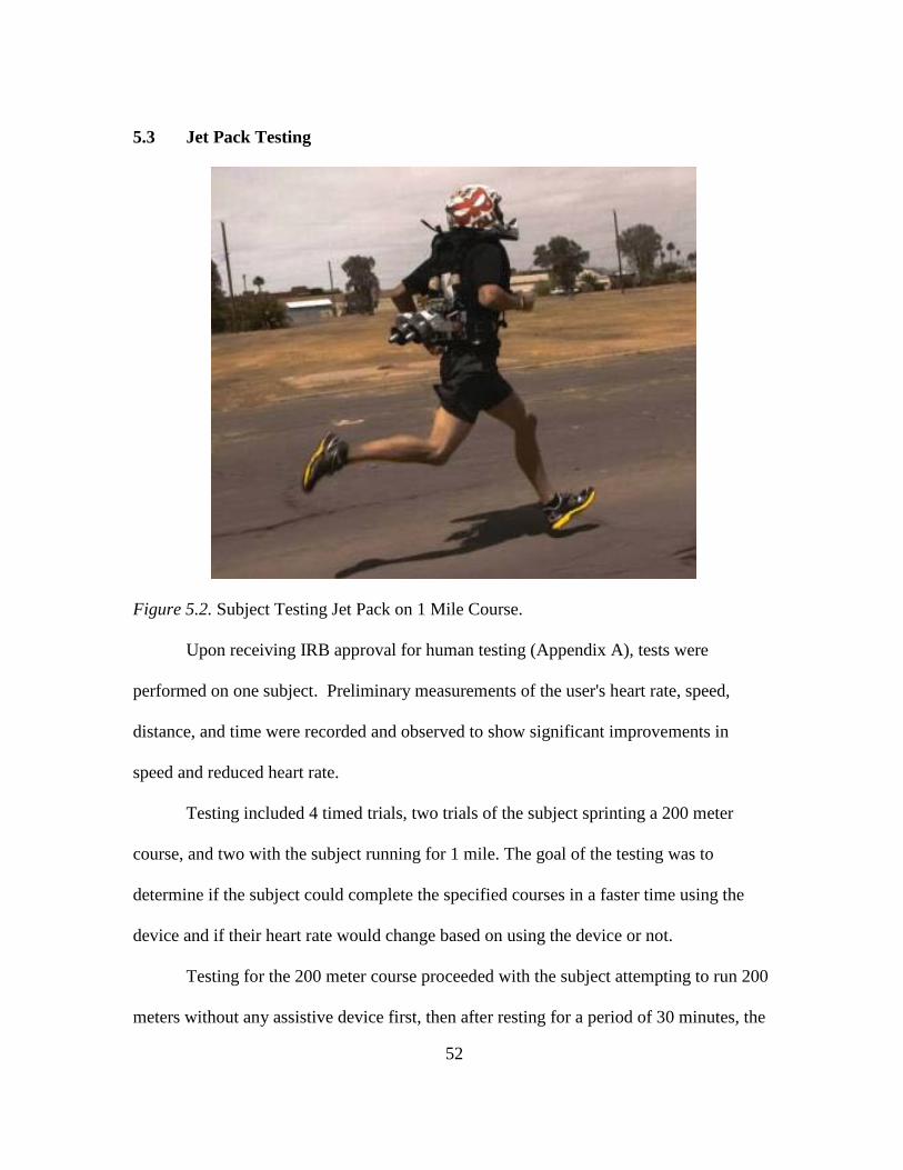
Figure 5.2. Subject Testing Jet Pack on 1 Mile Course.
Upon receiving IRB approval for human testing (Appendix A), tests were
performed on one subject. Preliminary measurements of the user's heart rate, speed,
distance, and time were recorded and observed to show significant improvements in
speed and reduced heart rate.
Testing included 4 timed trials, two trials of the subject sprinting a 200 meter
course, and two with the subject running for 1 mile. The goal of the testing was to
determine if the subject could complete the specified courses in a faster time using the
device and if their heart rate would change based on using the device or not.
Testing for the 200 meter course proceeded with the subject attempting to run 200
meters without any assistive device first, then after resting for a period of 30 minutes, the
53
subject ran the same 200 meters with the device. The primary test demonstrated a
decrease in time of 3 seconds required to run the 200 meter course. The Subject
completed the first 200 meter trial in 28 seconds with no device and completed the same
course in 25 seconds with the device.
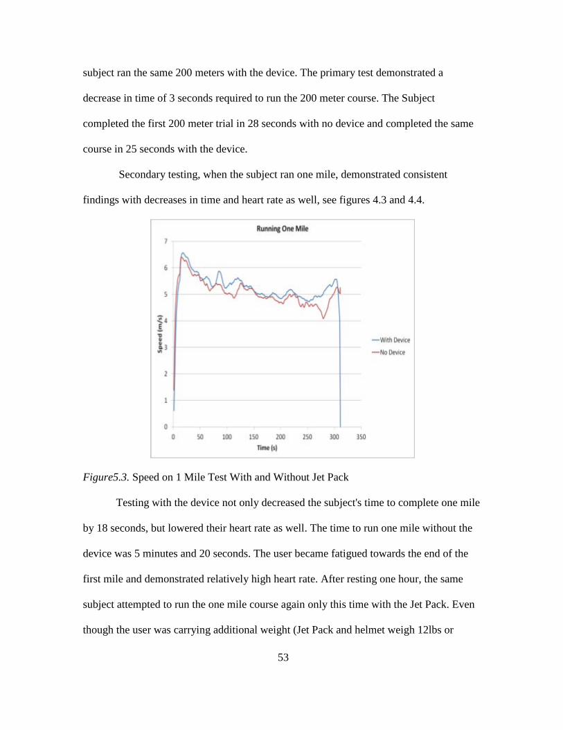
Secondary testing, when the subject ran one mile, demonstrated consistent
findings with decreases in time and heart rate as well, see figures 4.3 and 4.4.
Figure5.3. Speed on 1 Mile Test With and Without Jet Pack Testing with the device not only decreased the subject's time to complete one mile
by 18 seconds, but lowered their heart rate as well. The time to run one mile without the
device was 5 minutes and 20 seconds. The user became fatigued towards the end of the
first mile and demonstrated relatively high heart rate. After resting one hour, the same
subject attempted to run the one mile course again only this time with the Jet Pack. Even
though the user was carrying additional weight (Jet Pack and helmet weigh 12lbs or

54
5.4kg), they were capable of completing the same course and distance with a time of 5
minutes and 2 seconds. These findings show that even when carrying additional weight, a
runner can sustain higher speeds for longer periods of time when utilizing the Jet Pack as
shown by an increase in average and peak speeds. A reduction in metabolic cost can be
assumed based on a decrease in average and peak heart rates even with subject carrying
an additional 12lbs and running faster.
Figure 5.4. Heart Rate on 1 Mile Test With and Without Jet Pack
55
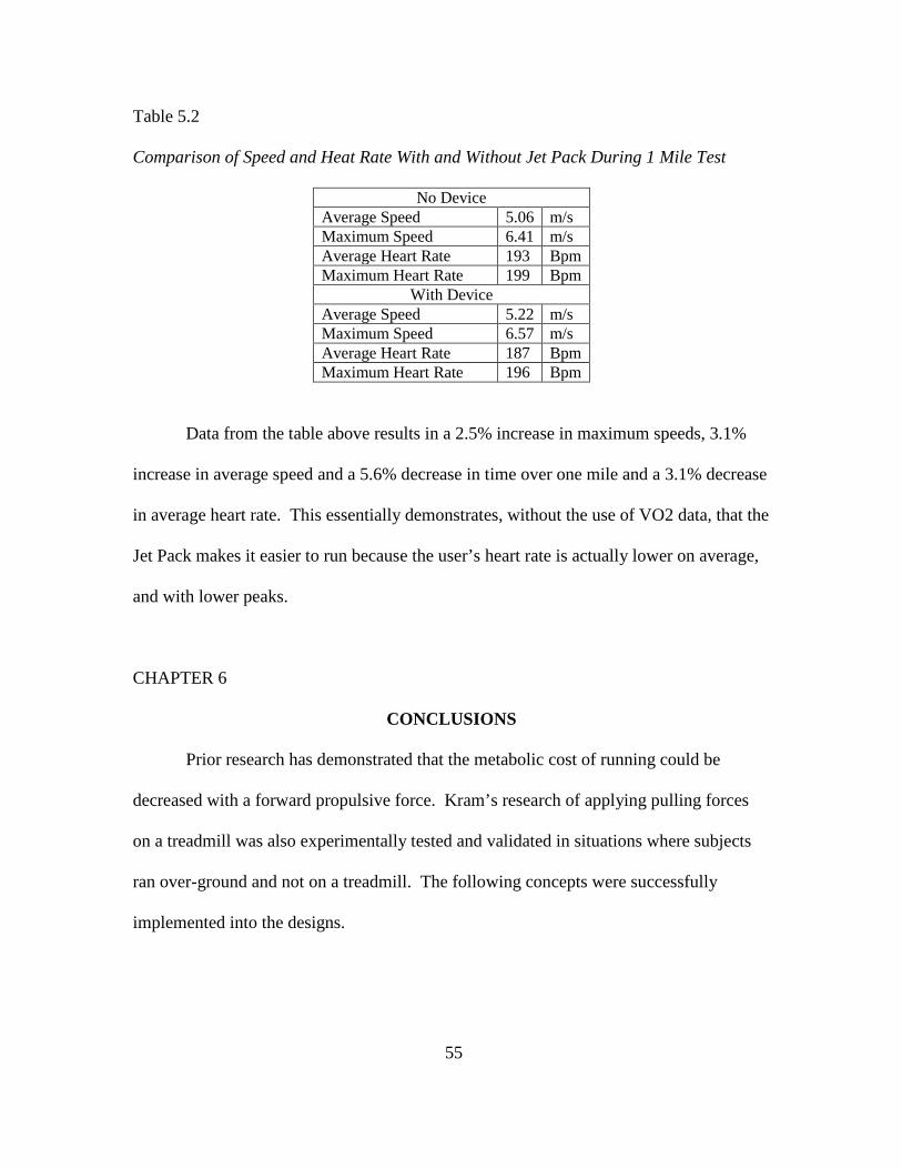
Table 5.2
Comparison of Speed and Heat Rate With and Without Jet Pack During 1 Mile Test
No Device Average Speed 5.06 m/s Maximum Speed 6.41 m/s Average Heart Rate 193 Bpm Maximum Heart Rate 199 Bpm
With Device Average Speed 5.22 m/s Maximum Speed 6.57 m/s Average Heart Rate 187 Bpm Maximum Heart Rate 196 Bpm
Data from the table above results in a 2.5% increase in maximum speeds, 3.1%
increase in average speed and a 5.6% decrease in time over one mile and a 3.1% decrease
in average heart rate. This essentially demonstrates, without the use of VO2 data, that the
Jet Pack makes it easier to run because the user’s heart rate is actually lower on average,
and with lower peaks.
CHAPTER 6
CONCLUSIONS
Prior research has demonstrated that the metabolic cost of running could be
decreased with a forward propulsive force. Kram’s research of applying pulling forces
on a treadmill was also experimentally tested and validated in situations where subjects
ran over-ground and not on a treadmill. The following concepts were successfully
implemented into the designs.

56
• An exoskeleton device consisting of pneumatic actuators connected to the legs
and ankles allows for running at high speeds while reducing the metabolic cost of
running.
• A soft-suit exoskeleton using cables connected to pneumatic actuators at the users
back and knees will assist human locomotion and reduce metabolic cost for
running while allowing for unrestricted motion.
• A propulsive device at the users back will assist human locomotion and reduce
the metabolic cost for running
Three devices were designed and fabricated to successfully augment running by either
adding a pure external force or by transferring mechanical energy through the legs of a
user. In all cases, the devices demonstrated that successful augmentation is possible if
the devices do not hinder the user with over complicated actuators and mechanisms. They
also demonstrate the need for a robust and precise controller such as one designed around
the phase oscillator. Furthermore, machines that are successful at augmenting human
locomotion help only the muscle groups that expend the most energy and do not try to
help all possible movement.
Over all, each device has different characteristics which result in different
performance abilities. AirLegs V1 can not only help reduce the metabolic cost of high
speed running, but it can help users push off the ground with even greater force by using
an artificial tendon. AirLegs V2 allows users to gain assistance with the stance phase
and push off while also offering a very flexible, unrestrictive method of attaching to the
human. Also, The Jet Pack is capable of assisting nearly any user without modification
or reconfiguration because of its simplicity. Furthermore, this research thesis
57
demonstrated that robotic assistive devices can have off the shelf components, with few
sensors and still operate as intended. This is a very important aspect because it shows the
potential for assistive devices to become universal, assisting nearly anyone. If research is
continued in a manner such as this thesis, focusing on minimalistic designs that are
efficient and precise, the industry of wearable robotics and robotic assistive devices will
soon be available to the masses.

58
REFERENCES
Behrens Matthew J. and Shawn Simonson. "A Comparison of the Various Methods Used to Enhance Sprint Speed" Strength and Conditioning Journal 33.2 (2011): 64-71.
Blickhan, "The Spring-Mass Model for Running and Hopping," Journal of Biomechanics, vol. 22, pp. 1217-1227, 1989
Ceruzzi, Paul E. (May 2003). A History of Modern Computing (2nd ed.). MIT Press. pp. 220–221. ISBN 0-262-53203-4.
Chu, A., Kazerooni, H. and Zoss, A. (2005) ‘On the Biomimetic Design of the Berkeley Lower Extremity Exoskeleton’, Proceedings of the 2005 IEEE International Conference on Robotics and Automation, Barcelona, Spain, pp. 4356 – 4363 (April)
Donatelli RA. The Biomechanics of the Foot and Ankle. F.A. Davis Company. 1996; (2nd edition).
Fletcher, C. (1974) The Complete Walker’, Alfred Knopf, New York
General Electric Co. (1968) ‘Hardiman I Prototype Project, Special Interim Study’, General Electric Report S6-68-1060, Schenectady, NY 1968
Graham and McRuer, "Phase Plane Analysis," in Analysis of Nonlinear Control Systems, ed: Dover Press, 1971.
Hamner, Samuel R., Ajay Seth, and Scott L. Delp. "Muscle Contributions to Propulsion and Support during Running." Journal of Biomechanics 43.14 (2010): 2709-716.
Hitt, J Bellman, M. Holgate, T. Sugar, and K. Hollander, "The Project: Design and Analysis of a Robotic Transtibial Prosthesis with Regenerative Kinetics," in ASME International Design Engineering Technical Conference, 2007 Hogan, "Impedance Control: An Approach to Manipulation," in American Controls Conference, 1984, pp. 304-313
Holgate, A. W. Bohler, and T. G. Sugar, "Control algorithms for ankle robots: A reflection on the state-of-the-art and presentation of two novel algorithms," in Biomedical Robotics and Biomechatronics, 2008. BioRob 2008. pp. 97-102.

59
Kram, R. and Grabowski A. M. "Running with horizontal pulling forces: the benefits of towing," Eur J Appl Physiology, vol. 104, pp. 473-479, 2008.
Ollinger G. Aguirre-, J. E. Colgate, M. A. Peshkin, and A. Goswami, "A 1-DOF Assistive Exoskeleton with Virtual Negative Damping: Effects on the Kinematic Response of the Lower Limbs," in IEEE/RSJ International Conference on Intelligent Robots and Systems, 2007 A. Seyfarth, H. Geyer, M. Gunthera, and R. Blickhan, "A movement criterion for running," Journal of Biomechanics, vol. 35, pp. 649–655, 2002.
Vaughan, C., & Davis, B. (1992). Dynamics of human gait. Champaign, Ill.: Human Kinetics.
Wang S., W. van Dijk, and H. van der Kooij, "Spring Uses in Exoskeleton Actuation Design," in IEEE International Conference on Rehabilitation Robotics, 2011.
Yagin, Nicholas. "Apparatus for Facilitating Walking". US patent 440684 filed February 11, 1890 and issued November 18, 1890.
Zanotto, D., Lenzi, T., Stegall, P., & Agrawal, S. K. (2013). Improving
transparency of powered exoskeletons using force/torque sensors on the supporting cuffs. IEEE ...International Conference on Rehabilitation Robotics

60
APPENDIX A
JETPACK IRB PROTOCOL AND CONSENT DOCUMENTATION

61

62
63
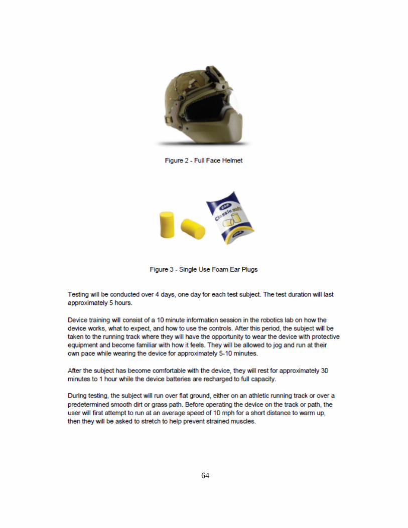
64

65

66

67

68

69

70
71
72