Embed Size (px)
Citation preview
Robot Vision SS 2009 Matthias Rüther 1
ROBOT VISION Lesson 5: Camera Hardware and Technology
Matthias Rüther
Robot Vision SS 2009 Matthias Rüther 2
Content
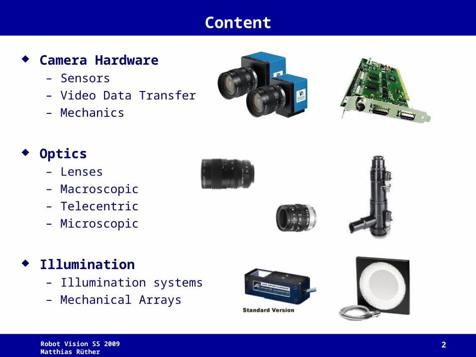
Camera Hardware– Sensors
– Video Data Transfer
– Mechanics
Optics– Lenses
– Macroscopic
– Telecentric
– Microscopic
Illumination– Illumination systems
– Mechanical Arrays
Robot Vision SS 2009 Matthias Rüther 3
Sensors
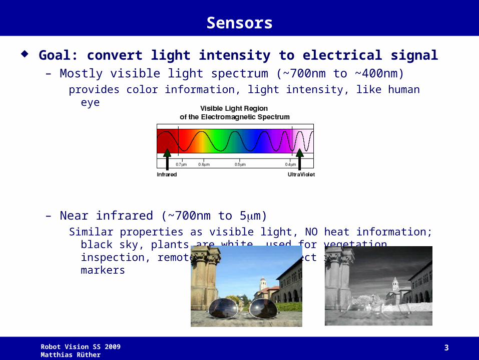
Goal: convert light intensity to electrical signal– Mostly visible light spectrum (~700nm to ~400nm)
provides color information, light intensity, like human eye
– Near infrared (~700nm to 5m)Similar properties as visible light, NO heat information; black sky, plants are
white, used for vegetation inspection, remote sensing, to detect reflective markers
Robot Vision SS 2009 Matthias Rüther 4
Sensors
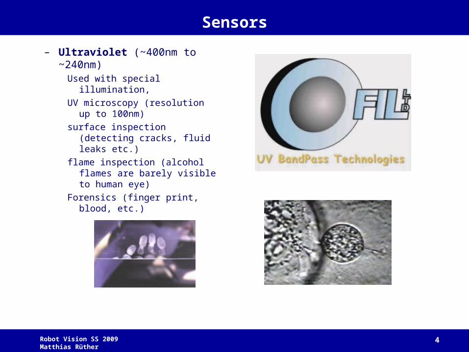
– Ultraviolet (~400nm to ~240nm)Used with special illumination,
UV microscopy (resolution up to 100nm)
surface inspection (detecting cracks, fluid leaks etc.)
flame inspection (alcohol flames are barely visible to human eye)
Forensics (finger print, blood, etc.)
Robot Vision SS 2009 Matthias Rüther 5
Sensors
2 Basic Technologies:
Charge Coupled Device (CCD)
CMOS Sensor (CMOS)
Both are pixelated metal oxide semiconducters
Accumulate in each pixel signal charge proportional to local illumination intensity => spatial sampling function
Robot Vision SS 2009 Matthias Rüther 6
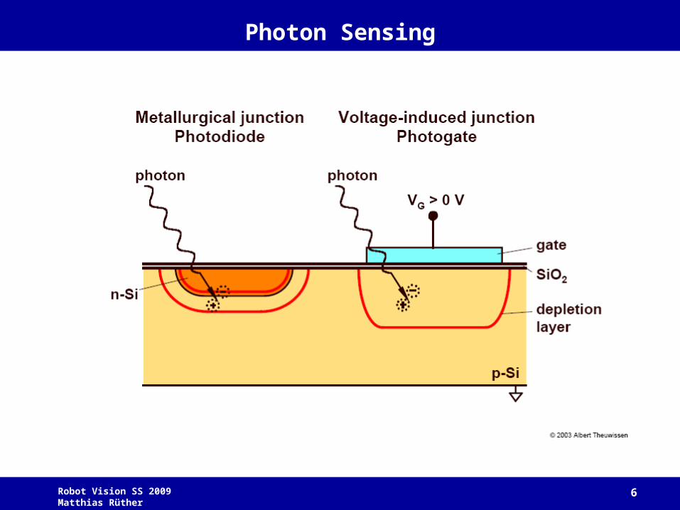
Photon Sensing
Robot Vision SS 2009 Matthias Rüther 7
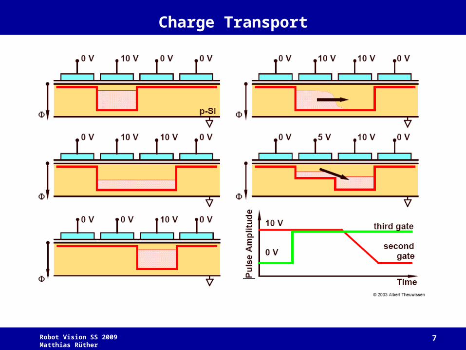
Charge Transport

Robot Vision SS 2009 Matthias Rüther 8
Read Out
Robot Vision SS 2009 Matthias Rüther 9
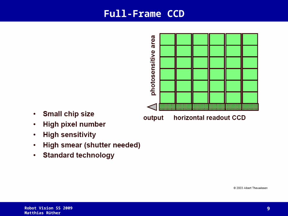
Full-Frame CCD
Robot Vision SS 2009 Matthias Rüther 10
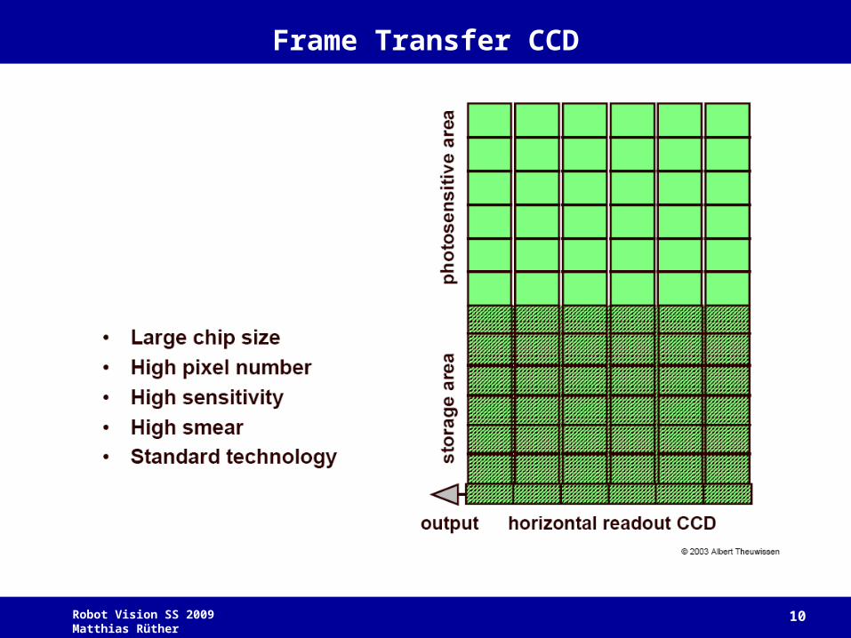
Frame Transfer CCD
Robot Vision SS 2009 Matthias Rüther 11
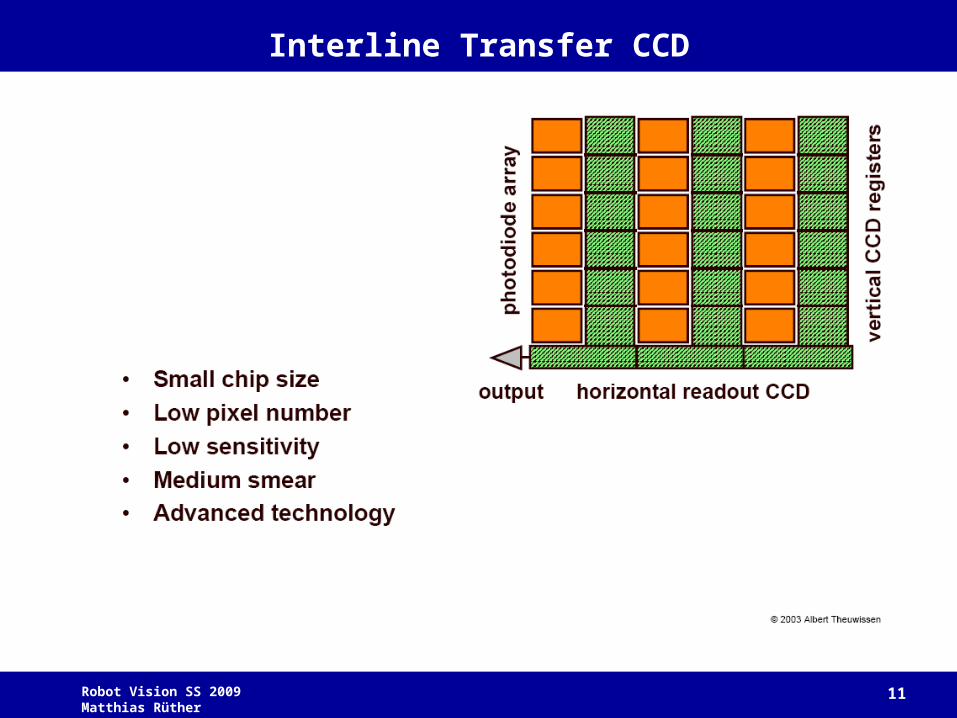
Interline Transfer CCD
Robot Vision SS 2009 Matthias Rüther 12
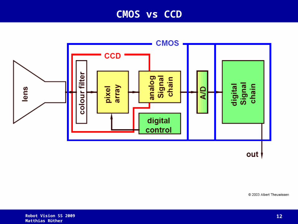
CMOS vs CCD
Robot Vision SS 2009 Matthias Rüther 13
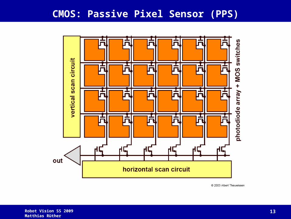
CMOS: Passive Pixel Sensor (PPS)

Robot Vision SS 2009 Matthias Rüther 14
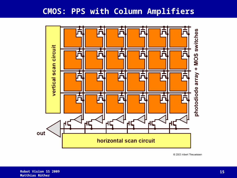
CMOS: PPS with Column Amplifiers
Robot Vision SS 2009 Matthias Rüther 15
CMOS: PPS with Column Amplifiers
Robot Vision SS 2009 Matthias Rüther 16
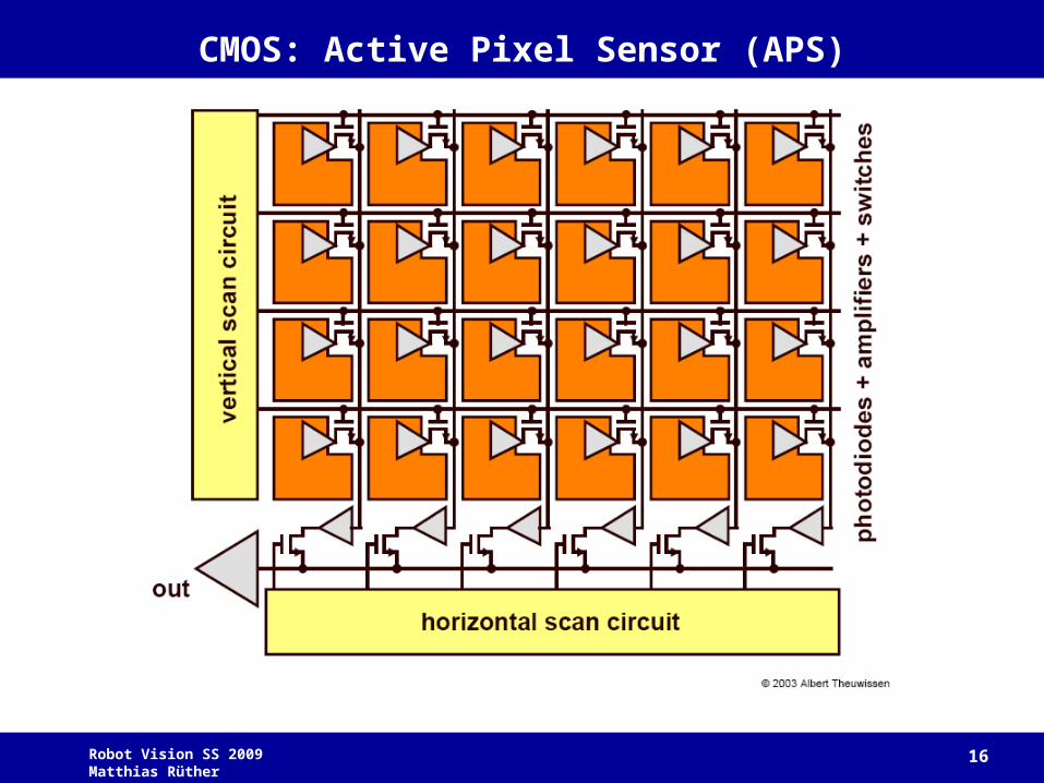
CMOS: Active Pixel Sensor (APS)
Robot Vision SS 2009 Matthias Rüther 17
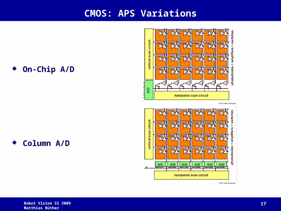
CMOS: APS Variations
On-Chip A/D
Column A/D
Robot Vision SS 2009 Matthias Rüther 18
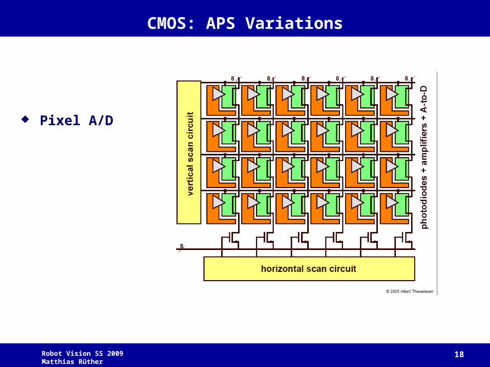
CMOS: APS Variations
Pixel A/D
Robot Vision SS 2009 Matthias Rüther 19
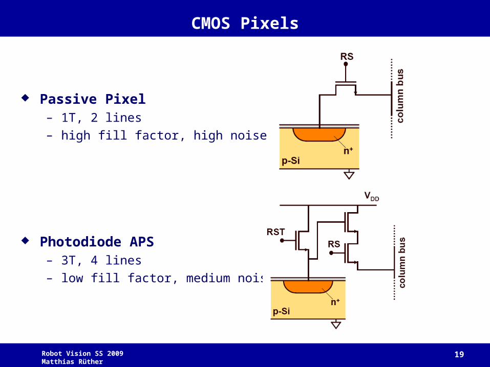
CMOS Pixels
Passive Pixel– 1T, 2 lines
– high fill factor, high noise
Photodiode APS– 3T, 4 lines
– low fill factor, medium noise
Robot Vision SS 2009 Matthias Rüther 20
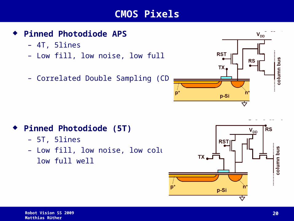
CMOS Pixels
Pinned Photodiode APS– 4T, 5lines
– Low fill, low noise, low full well
– Correlated Double Sampling (CDS)
Pinned Photodiode (5T)– 5T, 5lines
– Low fill, low noise, low column FPN,
low full well
Robot Vision SS 2009 Matthias Rüther 21
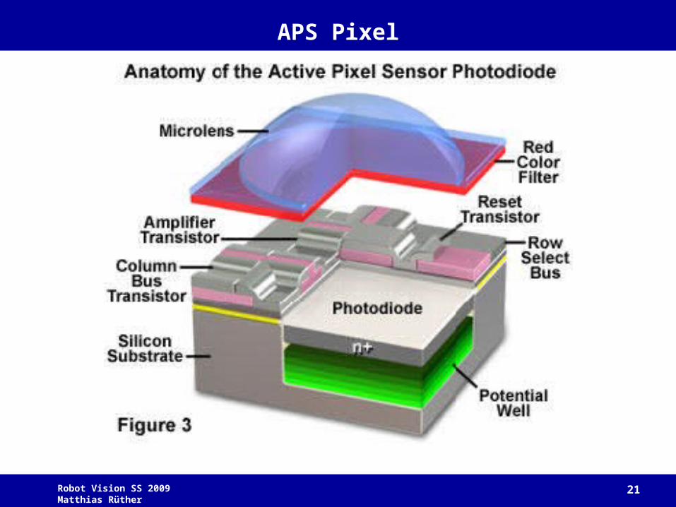
APS Pixel
Robot Vision SS 2009 Matthias Rüther 22
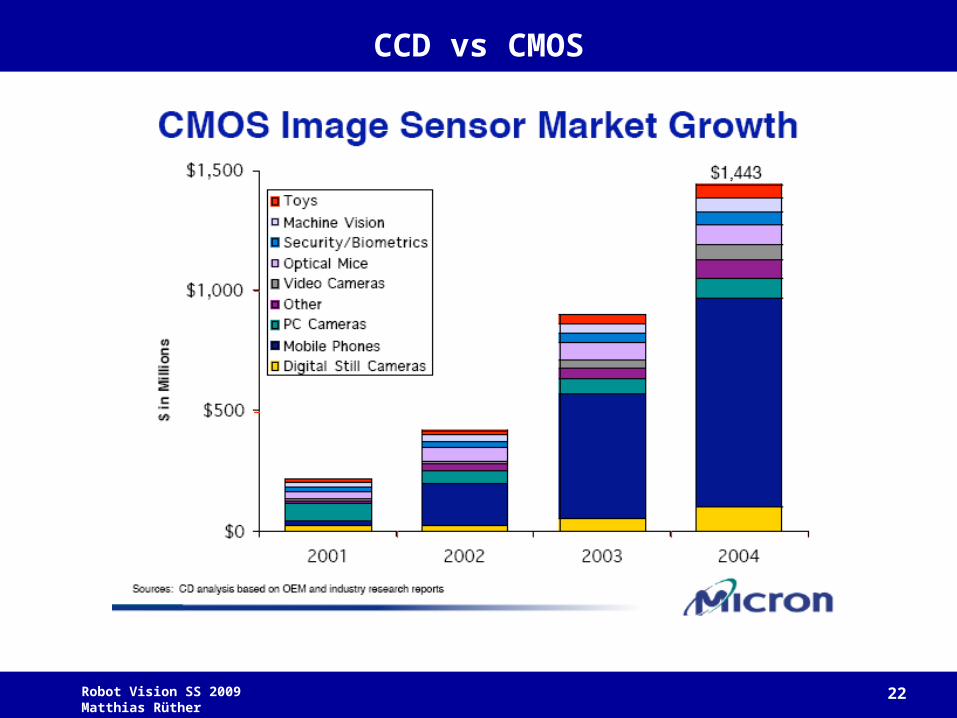
CCD vs CMOS
Robot Vision SS 2009 Matthias Rüther 23
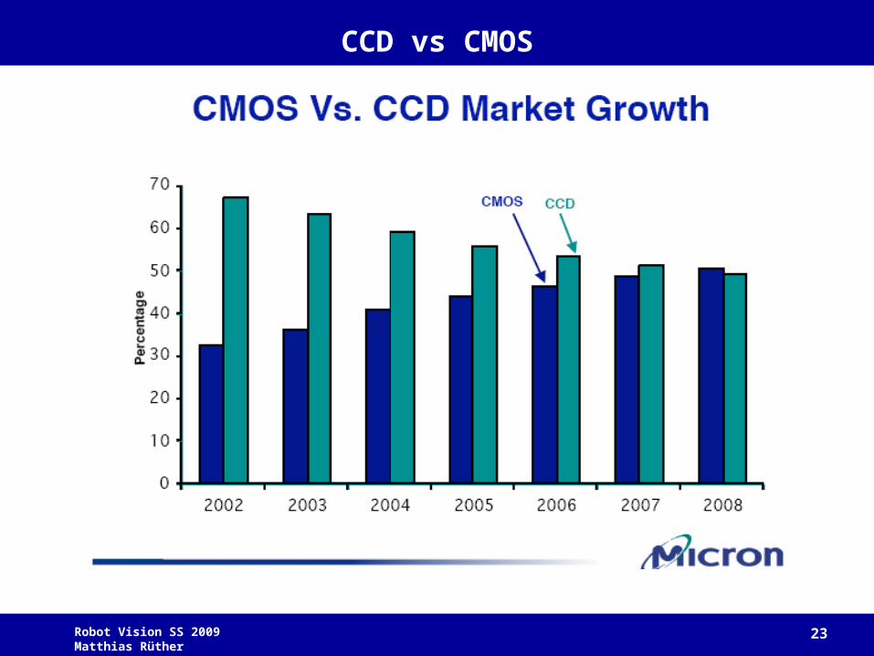
CCD vs CMOS
Robot Vision SS 2009 Matthias Rüther 24
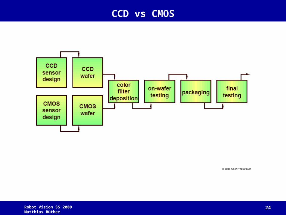
CCD vs CMOS
Robot Vision SS 2009 Matthias Rüther 25
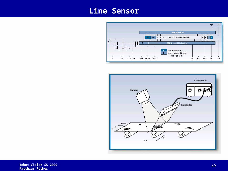
Line Sensor
Robot Vision SS 2009 Matthias Rüther 26
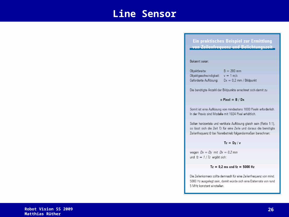
Line Sensor
Robot Vision SS 2009 Matthias Rüther 27
Video Data Transfer
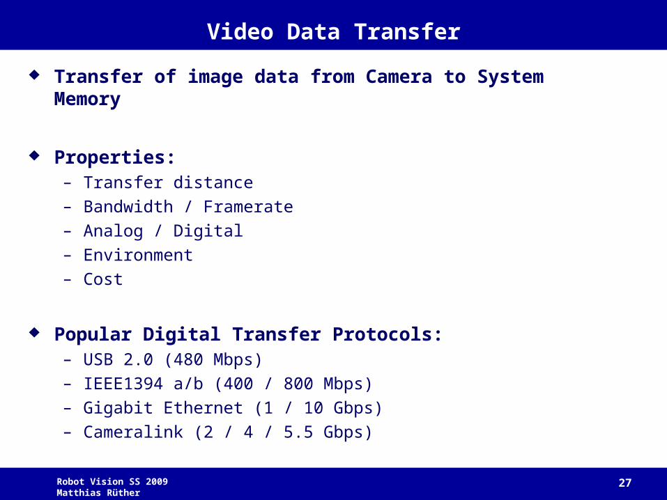
Transfer of image data from Camera to System Memory
Properties:– Transfer distance
– Bandwidth / Framerate
– Analog / Digital
– Environment
– Cost
Popular Digital Transfer Protocols: – USB 2.0 (480 Mbps)
– IEEE1394 a/b (400 / 800 Mbps)
– Gigabit Ethernet (1 / 10 Gbps)
– Cameralink (2 / 4 / 5.5 Gbps)
Robot Vision SS 2009 Matthias Rüther 28
CameraLink
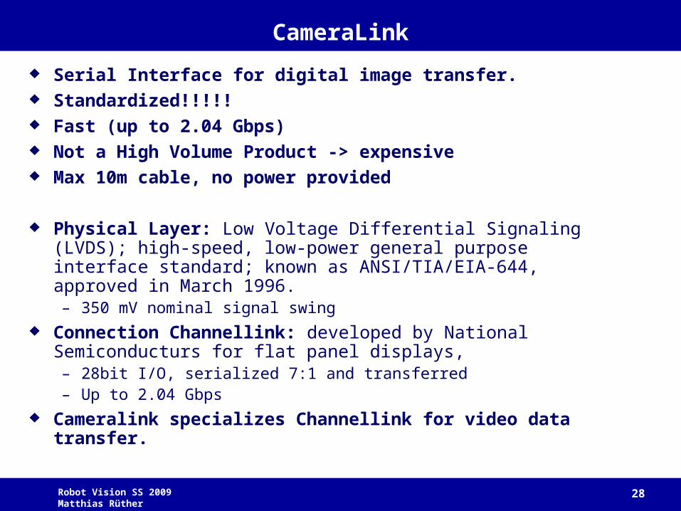
Serial Interface for digital image transfer. Standardized!!!!! Fast (up to 2.04 Gbps) Not a High Volume Product -> expensive Max 10m cable, no power provided
Physical Layer: Low Voltage Differential Signaling (LVDS); high-speed, low-power general purpose interface standard; known as ANSI/TIA/EIA-644, approved in March 1996.– 350 mV nominal signal swing
Connection Channellink: developed by National Semiconducturs for flat panel displays, – 28bit I/O, serialized 7:1 and transferred– Up to 2.04 Gbps
Cameralink specializes Channellink for video data transfer.
Robot Vision SS 2009 Matthias Rüther 29
CameraLink
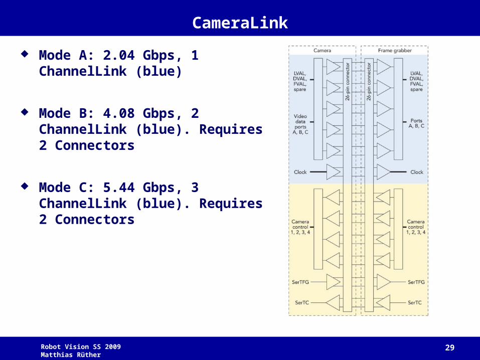
Mode A: 2.04 Gbps, 1 ChannelLink (blue)
Mode B: 4.08 Gbps, 2 ChannelLink (blue). Requires 2 Connectors
Mode C: 5.44 Gbps, 3 ChannelLink (blue). Requires 2 Connectors
Robot Vision SS 2009 Matthias Rüther 30
IEEE 1394 (Firewire)
De-facto industrial standard, being replaced by GigE
– Moderate volume product (Industrial cameras, Video Cameras, Webcams)– Consists of both hardware and software specification– Completely digital--no conversion to analog – Data rates of 100, 200, or 400 Mb per second (800Mbps by 1394b)– Flexible--supports daisy-chain and branching cable configurations– Inexpensive – Max 4.5m cable length– 1394b may run over GOF (Glass Optical Fiber), hundreds of meters of cable
length
– Power provided by bus
– Invented by Apple in mid 90‘s as LAN bus (100Mbps)– Development hampered by license fees in 1998 ($1 per port)– Since 1999 owned by 1394LA ($0.25 per unit)– Firewire remains trademark of apple.
Robot Vision SS 2009 Matthias Rüther 31
USB 2.0
Upcoming rival for IEEE1394– Fast (480Mbps)
– High volume (available on every PC)
– Plug and Play
– Emerged from USB 1.1 (1995)
– Provides Power
– 5m cable length
– Master-Slave Architecture (IEEE1394: Peer to Peer)
– IEEE1394a is faster (10-70%), due to protocol architecture!
Robot Vision SS 2009 Matthias Rüther 32
GigE
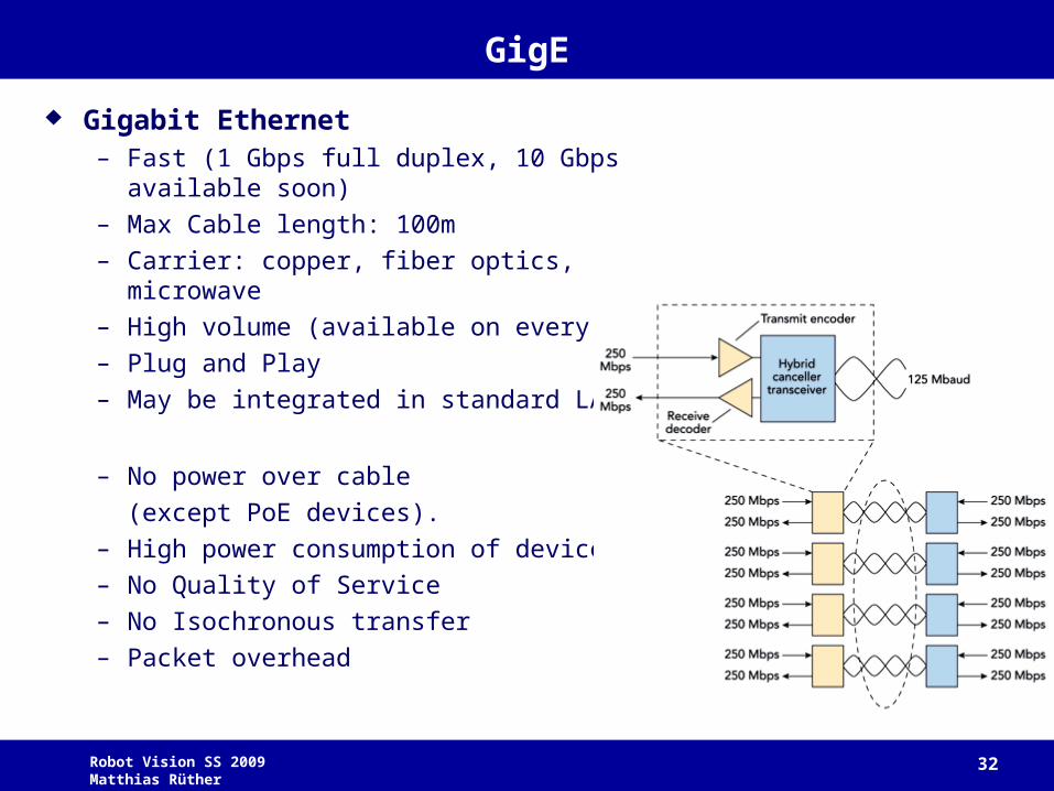
Gigabit Ethernet– Fast (1 Gbps full duplex, 10 Gbps available
soon)
– Max Cable length: 100m
– Carrier: copper, fiber optics, microwave
– High volume (available on every PC)
– Plug and Play
– May be integrated in standard LANs
– No power over cable
(except PoE devices).
– High power consumption of devices
– No Quality of Service
– No Isochronous transfer
– Packet overhead
Robot Vision SS 2009 Matthias Rüther 33
Mechanics
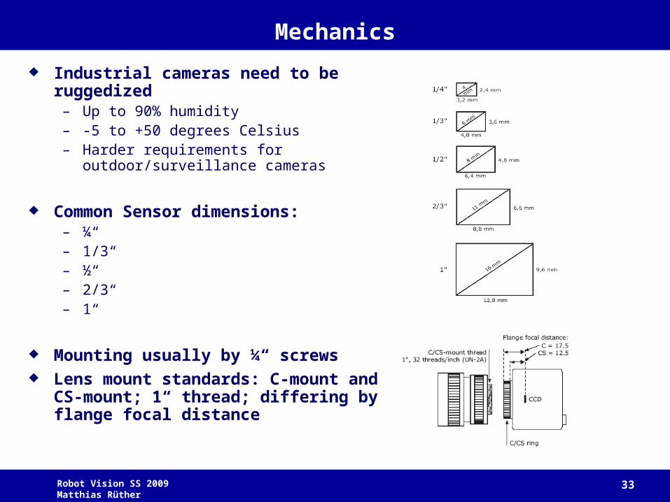
Industrial cameras need to be ruggedized
– Up to 90% humidity– -5 to +50 degrees Celsius– Harder requirements for
outdoor/surveillance cameras
Common Sensor dimensions:– ¼“– 1/3“– ½“– 2/3“– 1“
Mounting usually by ¼“ screws Lens mount standards: C-mount and
CS-mount; 1“ thread; differing by flange focal distance
Robot Vision SS 2009 Matthias Rüther 34
Optics
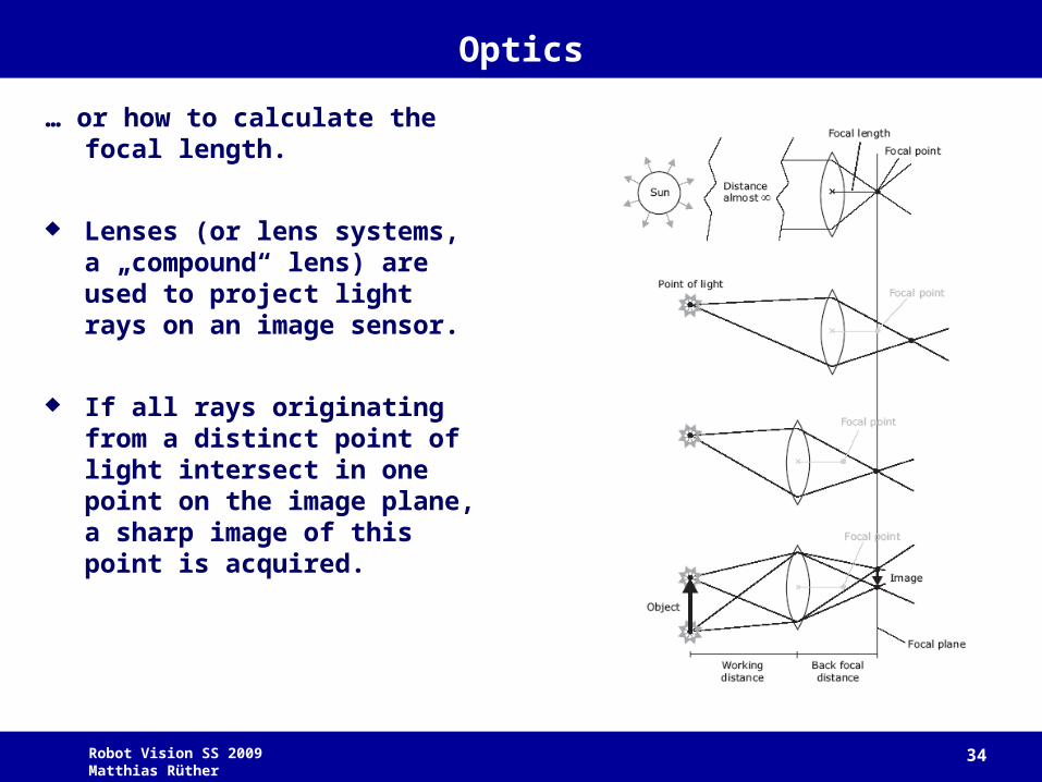
… or how to calculate the focal length.
Lenses (or lens systems, a „compound“ lens) are used to project light rays on an image sensor.
If all rays originating from a distinct point of light intersect in one point on the image plane, a sharp image of this point is acquired.
Robot Vision SS 2009 Matthias Rüther 35
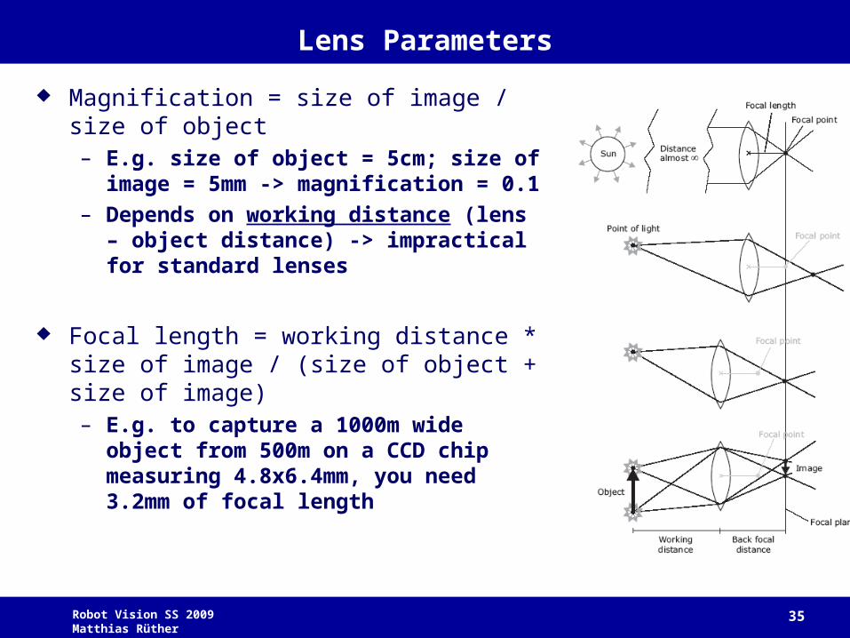
Lens Parameters
Magnification = size of image / size of object– E.g. size of object = 5cm; size of image =
5mm -> magnification = 0.1
– Depends on working distance (lens – object distance) -> impractical for standard lenses
Focal length = working distance * size of image / (size of object + size of image)– E.g. to capture a 1000m wide object from
500m on a CCD chip measuring 4.8x6.4mm, you need 3.2mm of focal length
Robot Vision SS 2009 Matthias Rüther 36
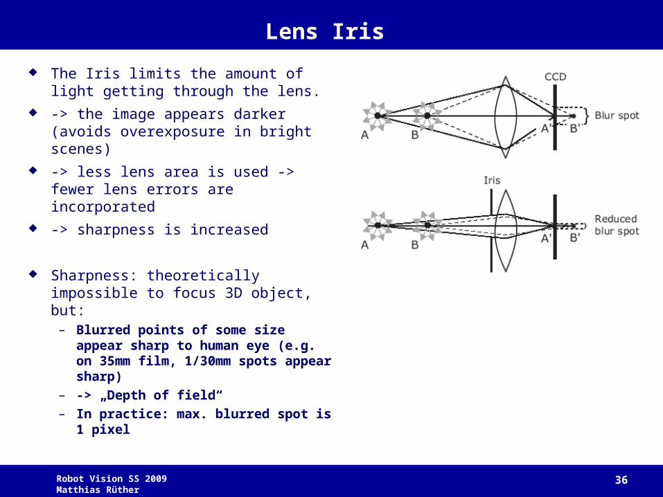
Lens Iris
The Iris limits the amount of light getting through the lens.
-> the image appears darker (avoids overexposure in bright scenes)
-> less lens area is used -> fewer lens errors are incorporated
-> sharpness is increased
Sharpness: theoretically impossible to focus 3D object, but:
– Blurred points of some size appear sharp to human eye (e.g. on 35mm film, 1/30mm spots appear sharp)
– -> „Depth of field“– In practice: max. blurred spot is 1
pixel
Robot Vision SS 2009 Matthias Rüther 37
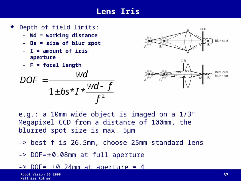
Lens Iris
Depth of field limits:– Wd = working distance– Bs = size of blur spot– I = amount of iris aperture– F = focal length
2**1ffwd
Ibs
wdDOF
e.g.: a 10mm wide object is imaged on a 1/3“ Megapixel CCD from a distance of 100mm, the blurred spot size is max. 5μm
-> best f is 26.5mm, choose 25mm standard lens
-> DOF=0.08mm at full aperture
-> DOF= 0.24mm at aperture = 4
Robot Vision SS 2009 Matthias Rüther 38
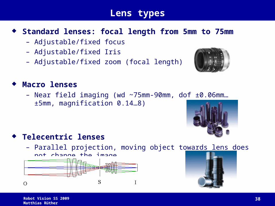
Lens types
Standard lenses: focal length from 5mm to 75mm– Adjustable/fixed focus
– Adjustable/fixed Iris
– Adjustable/fixed zoom (focal length)
Macro lenses– Near field imaging (wd ~75mm-90mm, dof ±0.06mm… ±5mm,
magnification 0.14…8)
Telecentric lenses– Parallel projection, moving object towards lens does not change the
image
Robot Vision SS 2009 Matthias Rüther 39
Lighting
Illumination is the most critical part in a machine vision system.
Small illumination changes may severely affect performance of vision algorithms.
If possible, adjust lighting conditions and keep them fixed!
Properties:– Intensity
– Spectrum
– Frequency (amplitude change: flicker, strobe)
– Direction
Hazards:– Object: reflection, specularity, color, stray light, transparency, motion
– Lamp: heat, flicker, stability, lifetime, size, power, speed
Robot Vision SS 2009 Matthias Rüther 40
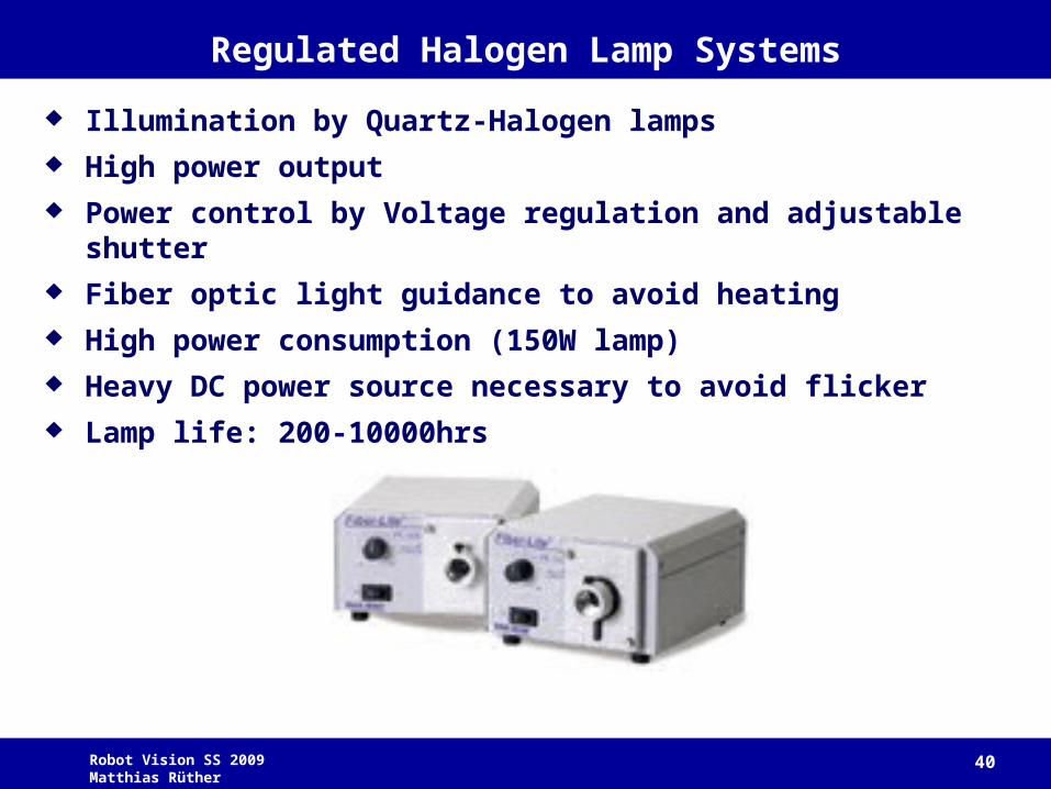
Regulated Halogen Lamp Systems
Illumination by Quartz-Halogen lamps
High power output
Power control by Voltage regulation and adjustable shutter
Fiber optic light guidance to avoid heating
High power consumption (150W lamp)
Heavy DC power source necessary to avoid flicker
Lamp life: 200-10000hrs
Robot Vision SS 2009 Matthias Rüther 41
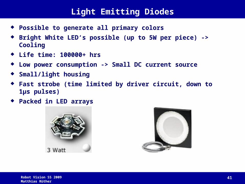
Light Emitting Diodes
Possible to generate all primary colors
Bright White LED‘s possible (up to 5W per piece) -> Cooling
Life time: 100000+ hrs
Low power consumption -> Small DC current source
Small/light housing
Fast strobe (time limited by driver circuit, down to 1μs pulses)
Packed in LED arrays
Robot Vision SS 2009 Matthias Rüther 42
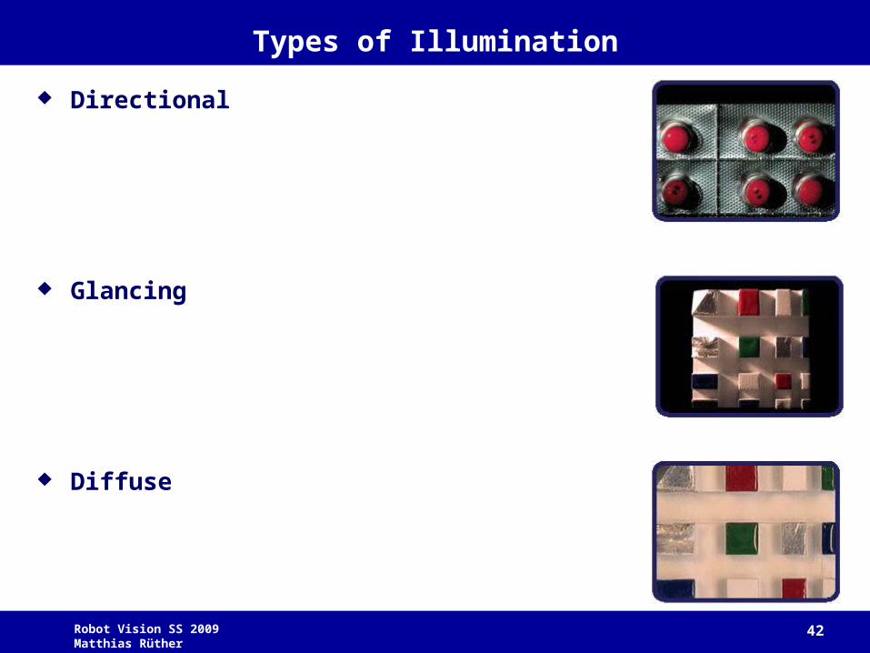
Types of Illumination
Directional
Glancing
Diffuse
Robot Vision SS 2009 Matthias Rüther 43
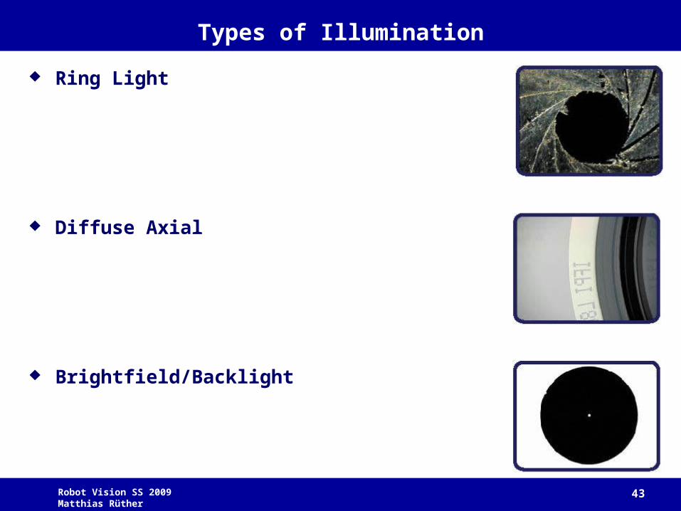
Types of Illumination
Ring Light
Diffuse Axial
Brightfield/Backlight
Robot Vision SS 2009 Matthias Rüther 44
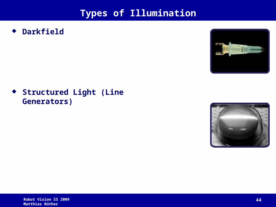
Types of Illumination
Darkfield
Structured Light (Line Generators)