Embed Size (px)
Citation preview

RoboScan Pro 918 user manual

©1998 - 1999 Martin Professional A/S, Denmark.
All rights reserved. No part of this manual may bereproduced, in any form or by any means, withoutpermission in writing from Martin Professional A/S,Denmark.
Printed in Denmark.
P/N 35000053, Rev. C

3 RoboScan Pro 918
section 1Introduction
Safety precautions.................................................................................................................................................... 4
section 2Setup
Unpacking ................................................................................................................................................................ 5Installing or changing the lamp.................................................................................................................................5Powering the fixture..................................................................................................................................................6Installation ...............................................................................................................................................................6Connecting the serial link ......................................................................................................................................... 7
section 3Control Panel
Personality settings ................................................................................................................................................10Protocol and address selection ..............................................................................................................................11Readouts ................................................................................................................................................................11Manual control ........................................................................................................................................................ 12Stand-alone sequences..........................................................................................................................................12Utilities....................................................................................................................................................................12
section 4Operation
Martin RS-485 control ............................................................................................................................................14DMX-512 control ....................................................................................................................................................14Stand-alone control ................................................................................................................................................14Controllable effects.................................................................................................................................................15
section 5Basic Service and Maintenance
Accessing parts ......................................................................................................................................................17Changing voltage and frequency settings ..............................................................................................................18Replacing fuses......................................................................................................................................................19Changing the XLR pin-out ......................................................................................................................................19Updating software .................................................................................................................................................. 19Custom gobos ........................................................................................................................................................ 20Changing rotating gobos ........................................................................................................................................20Changing color filters..............................................................................................................................................21Lamp replacement.................................................................................................................................................. 21Optimizing lamp alignment .....................................................................................................................................21Cleaning .................................................................................................................................................................22Lubrication.............................................................................................................................................................. 22
section 6Appendices
DMX Protocol ........................................................................................................................................................ 23Error Messages ......................................................................................................................................................28Troubleshooting .....................................................................................................................................................29Circuit Board Layout ...............................................................................................................................................30Specifications .........................................................................................................................................................31

4 Introduction
s e c t i o n 1
I N T RO D U C T I O N
Thank you for selecting the Martin RoboScan Pro 918. This scanner, with its highly efficient optical and thermaldesign, provides quiet operation and crisp, bright output in a compact, easy-to-handle package.
This manual covers all models of the RoboScan Pro 918 and describes the features found in CPU software version 1.4.The latest Pro 918 information and software is available from the Martin Professional web site at http://www.martin.dk.
S A F E T Y P R E C A U T I O N S
The RoboScan Pro 918 is for professional use only. It presents potential risks due to electrical shock, heat and ultra-violet radiation burns, lamp explosion, falls, high-intensity light, and fire. A thorough understanding of the dangers,genuine concern for safety, and attention to detail are required to prevent accidents. Read this manual before power-ing or installing the fixture, follow the safety precautions listed below and observe the warnings in this manualand printed on the fixture, and always double check the safety conditions. If you have questions about how tooperate the Pro 918, please contact your Martin dealer for assistance.
• $OZD\VýGisconnect the fixture from AC power before:- Changing the transformer or ballast settings- Installing or removing the lamp- Checking or replacing fuses- Removing any cover or part
• Replace the lamp before usage exceeds the maximum rated service life or if the lamp becomes defective or worn out. Allow the fixture to cool for 15 minutes before replacing the lamp.
• Keep all combustible materials (for example fabric, wood, paper) at least 0.5 meters (20 inches) away from the fixture. Keep flammable materials well away from the fixture.
• For protection against dangerous electric shock, always ground (earth) the fixture electrically. Use only a source of AC power that complies with local building and electrical codes. Do not expose the fixture to rain or moisture.
• Ensure that the air flow through fans and vents is free and unobstructed.
• When suspending the fixture above ground level, verify that the structure can hold at least 10 times the weight of all installed devices and secure the fixture with an approved safety cable. Block access below the work area whenever installing or removing the fixture.
• Refer any service operation not described in this manual to a qualified technician.
• The covers get very hot under normal operation: to avoid burns, locate the fixture where it cannot be accidentally touched or bumped, and allow the fixture to cool before servicing.
• Do not illuminate surfaces within 1 meter of the fixture.
• Never place filters or other materials over the lens or mirror.
• Do not operate the fixture if the ambient temperature (Ta) exceeds 40° C (104° F).
• Do not look directly into the light from a close distance.
• Never operate the fixture without all lenses and covers installed: an unshielded lamp can explode without warning and emits dangerous UV radiation that can cause burns and eye damage.
• Do not modify the fixture or install other than genuine Martin accessories and upgrade kits.

5 RoboScan Pro 918
s e c t i o n 2
S E T U P
This section describes the steps required to prepare the RoboScan Pro 918 for operation.
U N P A C K I N G
The RoboScan Pro 918 package includes:
• 1 5-meter, 3-pin shielded XLR control cable • 1 3-meter, 3-wire IEC power cable (EU version only) • 1 user manual• 9 extra rotating gobos• 1 spare rotating-gobo spring
The packing materials are carefully designed to protect the fixture during shipment - always use them or a customflight case to transport the fixture.
I N S T A L L I N G O R C H A N G I N G T H E L A M P
The RoboScan Pro 918 is designed to work with the Philips MSR-575/2, Philips MSD-575, or the Osram HSR-575/2discharge lamp. Installing any other lamp may damage the fixture. The lamp holder is pre-adjusted at the factory; pre-cise alignment may be necessary due to slight variations between lamps. The procedure is described on page 21.
W A R N I N G !Disconnect the fixture from AC power before proceeding. Always wear safety
goggles to protect your eyes and allow a hot lamp to cool for at least 15 minutes before removing it from the fixture.
1. The RoboScan Pro 918 must be cool and isolated from AC power. Remove the 2 screws (A) securing thelamp assembly to the back plate. Gently pull out the assembly.
2. If changing the lamp, remove the old lamp from the socket.
3. Holding the new lamp by its ceramic base (do not touch the glass), insert it firmly and squarely into the lampsocket. Clean the glass bulb with the cloth supplied with the lamp, particularly if your fingers touch the glass.A clean, lint-free cloth wetted with alcohol may also be used.
4. Reinsert the lamp assembly and replace the screws.
5. Before turning the lamp on, reset the RLAH and RLST counters. See “Readouts” on page 11.

6 Setup
PO W E R I N G T H E F I X T U R E
W A R N I N G !For protection from dangerous electric shock, the fixture must be grounded
(earthed). The AC mains supply shall be fitted with a fuse or circuit breaker and ground-fault protection.
1. Verify that the voltage and frequency settings match the local AC supply. These settings are printed on theserial number label next to the control panel. If the settings do not match the supply, then the ballast andtransformer must be rewired as described under “Changing voltage and frequency settings” on page 18.
2. You may need to install a cord cap that fits your supply on the power cable. Following the manufacturer’sinstructions, connect the wires as shown below. Note: The table shows some possible pin identificationschemes; if the pins are not clearly identified, or if you have any doubts about proper installation, consult aqualified electrician.
3. Verify that the supply cable is undamaged and rated for the current requirements of all connected devices.Do not connect the Pro 918 to a dimmer system: doing so will damage the fixture.
I N S T A L L A T I O N ý
U s i n g t h e m o u n t i n g b r a ck e t a s a f l o o r s t a n d
W A R N I N GWhen standing the fixture with the lamp end down, the end panel must be a min-
imum of 75 mm (3 in) above the floor to provide adequate circulation.
1. If standing the fixture with the mirror end up, loosen the mounting bracket and align the pointer with the lastindex line: the bracket shall not be placed any farther from the end. Tighten the clamps securely. Loosen theswivel locks and set the angle to the extreme position, marked as “-”. Tighten both swivel locks.
2. If standing the fixture with the mirror down, slide the mounting bracket to the mirror end and set the pointernear the last index line; the exact position is not critical. Tighten the clamps securely. Loosen the swivellocks and set the angle in between the 60° and 75° marks. Tighten both swivel locks.
3. Stand the fixture on a stable platform away from publicly trafficked areas. Verify that the fixture is stable;adjust the bracket if necessary.
Wire (EU) Wire (US) Pin Marking Screw (US)brown black live “L” yellow or brass
blue white neutral “N” silver
yellow/green green ground green

7 RoboScan Pro 918
R i g g i n gThe mounting bracket allows the Pro 918 to be rigged at any angle. The figure below shows the index position of thebalance point at different angles. Balancing the fixture makes it more stable and easier to work with, but it can be hungout of balance if necessary.
W A R N I N G !Attach an approved safety cable to the eye hook.
1. Loosen the clamps (B) on each side of the mounting bracket, slide thebracket to the approximate position, and partially tighten the clamps.
2. Loosen the swivel locks (E) and tilt the bracket to the desired angle.Partially tighten the locks.
3. Bolt rigging clamps that can bear at least 10 times the weight of the fix-ture to the mounting bracket. 1 clamp may be bolted to the center holeor 2 clamps may be bolted to the 2 outside holes (C). See page 31 forclamps available from Martin.
4. Verify that the structure can bear at least 10 times the weight of allinstalled fixtures, clamps, cables, auxiliary equipment, etc.
5. Block access below the work area. Working from a stable platform,place the fixture on the rigging.
6. Install a safety wire that can bear at least 10 times the weight of the fix-ture. Use the eye hook (D) to fasten the safety wire to the fixture. Neveruse the carrying handles or mounting bracket for secondary attach-ment.
7. Tighten the rigging clamp(s) securely to the structure.
8. Fine-tune the position and the fully tighten the slide clamps and swivellocks.
C O N N E C T I N G T H E S E R I A L L I N K
The default pin-out is compatible with DMX-512.
The Pro 918’s 3-pin data sockets are configured for DMX controllers, i.e., pin 1 to shield, pin 2 to cold (-) and pin 3 tohot (+). As many devices have 5-pin connectors or 3-pin connectors with reversed polarity on pins 2 and 3, adaptorcables may be required.
1. Connect the controller’s data output to the RoboScan Pro 918’s data input. For a
• DMX controller with 5-pin output: use a cable with 5-pin male and 3-pin female connectors such as P/N 11820005. Pins 4 and 5 are not used.
• DMX controller with 3-pin output: use a normal cable with 3-pin male and female connectors.• Martin RS-485 Protocol controller: use a phase-reversing cable, such as P/N 11820006, with 3-pin male and female
connectors, or reconfigure the data sockets as described on page 19.
+60°
, A0
+45°
, B2
+30°, C0
+15°, C3
0°, D2
-15°, E0
>+75
°, e
nd
>-75°, end
-30°, E4-45°, F4-60°, G2
Phase-ReversingCable
Male Female
123
123
3-pin to 3-pin
Connections
P/N 11820006
Phase-ReversingCable
Male Female
123
12345
3-pin to 5-pin
Connections
P/N 11820002
Phase-ReversingCable
Male Female
12345
123
5-pin to 3-pin
Connections
P/N 11820003
StraightCable
Male Female
12345
123
5-pin to 3-pin
Connections
P/N 11820005
Straight Cable
Male Female
123
12345
3-pin to 5-pin
Connections
P/N 11820004

8 Setup
2. Continue the link: connect the output of the fixture closest to the controller to the input of the next fixture.Use a phase-reversing cable when connecting a DMX-standard (pin 3 +) device to a Martin-standard (pin 3-) device.
3. Insert a male 120 Ω XLR termination plug in the output of the last fixture on the link.
T i p s fo r bu i l d i n g a s e r i a l l i n k • Use shielded twisted-pair cable designed for RS-485 devices: standard microphone cable cannot transmit DMX data
reliably over long runs. For links up to 300 meters (1000 ft.) long, you can use 24 AWG, low capacitance, 85-150 ohm characteristic impedance, shielded cable with 1 or more twisted pairs. For runs up to 500 meters (1640 ft.) use 22 AWG cable. Use an amplifier if the serial link exceeds 500 meters.
• Never use a “Y” connector to split the link. To split the serial link into branches use a splitter such as the Martin 4-Channel Opto-Isolated RS-485 Splitter/Amplifier.
• Do not overload the link. Up to 32 devices may be connected on a serial link. • Terminate the link by installing a termination plug in the output socket of the last fixture on the link. The termination
plug, which is simply a male XLR connector with a 120 ohm, 0.25 watt resistor soldered between pins 2 and 3, “soaks up” the control signal so it does not reflect back down the link and cause interference. If a splitter is used, terminate each branch of the link.

9 RoboScan Pro 918
s e c t i o n 3
C O N T RO L PA N E L
The 4-digit LED control panel allows you to set the address and personalities, read lamp hours and other information,calibrate effects, control the fixture manually, and run stand-alone tests and demo programs. Most of these functionsmay be performed remotely via the serial link with the MPBB1 Uploader.
The display can be flipped for easy reading by pressing the >↑@ and >↓@ keys simultaneously. The intensity is adjustableand the display can be set to go out 2 minutes after the last key-press.
The DMX or Martin address, depending on the protocol setting, and any error messages are displayed when theRoboScan Pro 918 is turned on. To enter the menu, press >MENU@ï Use the >↑@ and >↓@ keys to move within the menu.To select a function or submenu, press >ENTER@. To escape a function or menu, press >MENU@.
G$GU 0$GU 7,0( $G- &$/ 3$7, 9(536(7 0$1 G0;/ 3763 63(&G(02
$GGUHVV20HVVDJHV
3R#+
53R+
/$#+
5/$+
/675
5/67
567
/#21
/R))
);
3$7,
&42)
&52)
5*2)
G#2) 6:$3
3,19
7,19
567
/#21
6+87
G,0
&2/4
&2/5
/R))
)JRE
5JRE
,5,6
35,62
3$1
7,/7
)2&8
)526
67&2
6+87
1111
(#63
&38
5384
G,63
)7<3
G,63
G/2)
G5(6
$/21
G,17
G)2)
83/G
3&E7
$872
6&87
G0$&
02G(
)767
G,0&2/4&2/5)JRE5JRE)2&8,5,635,6
'(043$17,/7)2&86(4
'(050,130$;30,170$;7)2&86(4
G)6()$&7&864&865&866
7(033&E);
76(4
G02G
())E
75$&02G(&$/
)*2)
)22)
J02G),;6&5/
37

10 Control Panel
PE R S O N A L I T Y S E T T I N G S
* Setting may be overridden via DMX. See protocol for details.
Personality Path Options Effect (Default settings shaded.)
Pan/tilt speed PTSPFAST Optimize mirror movement for speed.*
SLOW Optimize mirror movement for smoothness.*
Pan/tilt swap PATI/SWAPON Map DMX pan control to tilt channel and vice versa.
OFF Normal pan and tilt control.
Pan inverse PATI/PINVON Reverse DMX pan control, right Æ left.
OFF Normal pan control, left ÆÆÆÆ right.
Tilt inverse PATI/TINVON Reverse DMX tilt control, down Æ up.
OFF Normal tilt control, up ÆÆÆÆ down
Tracking algorithm SPEC/TRAC/MOdEMOd1 Absolute delta value algorithm (for most controllers)
MOd2 Real delta value algorithm
Tracking samples SPEC/TRAC/CAL 1 - 10Tracking mode sample level - default is 6. Higher levels give smoother movement but slower acceleration.
Fixture type SPEC/FTYPPRIS Operate with rotating prism .
FROS Operate with optional variable frost.
Display On/Off SPEC/dISPON Display stays on.
OFF Display goes out 2 minutes after last key press.
Display intensity SPEC/dINT 10 - 100 Adjust display intensity.
DMX lamp off SPEC/dLOFON Enable DMX lamp off command.
OFF Disable DMX lamp off command. *
DMX reset SPEC/dRESON Enable DMX reset command.
OFF Disable DMX reset command.*
Automatic lamp on SPEC/ALONON Lamp strikes automatically within 90 seconds of power on.
OFF Strike lamp from controller.
Automatic protocol detection
SPEC/AUTOON Enable automatic protocol detection.
OFF Disable automatic protocol detection.
Shortcuts SPEC/SCUTON
Color wheels and fixed-gobo wheel turn the shortest direction. *
OFF Wheels turn same direction.*
DMX macros SPEC/dMAC ON Enable DMX-selectable macros and pulsating effects.
OFF Disable DMX-selectable macros and pulsating effects
Fixed gobo mode SPEC/gMOdFIX Static gobo wheel steps between full positions
SCRL Static gobo wheel scrolls continuously
Studio mode SPEC/MOdENORM Optimize effects for speed.
STUd Optimize effects for silence.
Dimmer mode SPEC/dMOdNORM Normal dimming curve.
TUNG Simulated tungsten dimming curve.
Effects feedback SPEC/EFFb
ONEnable feedback on color wheels, fixed-gobo wheel, and rotating-gobo index.
OFFDisable feedback on color wheels, fixed-gobo wheel, and rotating-gobo index.
Tilt motor select SPEC/PTNEW For units after S/N 402908-0000 (selected automatically).
OLD For units before S/N 402908-0000 (selected automatically).

11 RoboScan Pro 918
P R O T O C O L A N D A D D R E S S S E L E C T I O N
7KHý5RER6FDQý3URýäìåýKDVýéý'0;ýRSHUDWLQJýPRGHVñýRUýSURWRFROVñýDQGýDý0DUWLQýPRGHïý7KHVHýDUHýGHVFULEHGýLQýPRUHGHWDLOýRQýSDJH ìéï
(DFKýIL[WXUHýPXVWýEHýDVVLJQHGýLWVýRZQýFKDQQHOVýWRýUHFHLYHýLQVWUXFWLRQVýIURPýWKHýFRQWUROOHUïý7KHýDGGUHVVñýDOVRýNQRZQýDVWKHýVWDUWýFKDQQHOñýLVýWKHýILUVWýFKDQQHOýXVHGïý$GGUHVVHVýDUHýLQGHSHQGHQWýRIýWKHýSK\VLFDOýRUGHUýRQýWKHýOLQNãýWKH\ýPD\ýEHýVHWLQýDQ\ýFRQYHQLHQWýRUGHUïý7ZRý3URýäìåVýPD\ýVKDUHýWKHýVDPHýDGGUHVVâýKRZHYHUñýWKH\ýZLOOýUHFHLYHýWKHýVDPHýLQVWUXFWLRQVDQGýLQGHSHQGHQWýFRQWUROýZLOOýQRWýEHýSRVVLEOHï
1. Apply power to the RoboScan Pro 918. Press the [MENU] key and then press [↑] or [↓] until the displayshows PSET. Press [ENTER].
2. Press [↑] or [↓] until the desired protocol appears on the display. Press [ENTER] to confirm.
3. Press [↑] or [↓] until the display shows dAdr (to set a DMX address) or MAdr (to set a Martinaddress). Press [ENTER] to confirm.
4. Press [↑] or [↓] to select a DMX address from 1 to 512 or a Martin address from 1 to 31. Press[ENTER] to confirm.
5. Press [MENU] to return to the main menu. Depending on the protocol selected, the DMX or Martinaddress is displayed.
R E A D O U T S
U s a g e r e a d o u t s ( TIME)Read the total number of power-on hours (Po H), power-on hours since last reset (RPoH), total lamp hours (LA H),lamp hours since last reset (RLAH), total number of lamp strikes (LSTR), and the number of lamp strikes since lastreset (RLST).
The resettable counters may be used to track overall usage and lamp life. To reset to zero, display the readout and thenpress >↑@ for 5 seconds.
D M X va l u e r e a d o u t s ( dMXL)Read the DMX start code (STCO) and DMX values received for each effect. This is an easy way to check if the fix-ture is receiving the expected commands. This feature is not applicable in Martin mode.
S o f t w a r e v e r s i o n r e a d o u t s ( VER)Read the version number of the CPU software (CPU), 2051 microprocessor (2051 ), and display module software(dISP ). The CPU software version is also displayed for a moment at power up.
Te m p e r a t u r e r e a d o u t s ( SPEC/ TEMP)Read temperature at the main printed circuit board (PCb) and in the effects section (FX) in Celsius. Temperaturesbelow 25° C are shown as -25 ; temperatures above 100° C are shown as +100 .
The temperature sensors are calibrated at the factory and adjustment should not be necessary. The following procedurecalibrates the sensors if they give no or faulty readings.
1. Allow the unit to cool to room temperature (powered off for at least 4 hours).
2. Measure the room temperature in Celsius. (To convert F° to C°, subtract 32° and then multiply by 0.555.)
3. Power up the unit and allow it to reset.
4. Press the [MENU] and [↓] keys at the same time and hold them for 3 seconds until “25” shows in the display.
5. Press the [↑] and [↓] keys until the display shows the temperature measured.
6. Press [ENTER] to save the setting.
Mode Martin DMX 1 DMX 2 DMX 3 DMX 4Control Vector Tracking Tracking and/or Vector
Pan/tilt resolution 16 bit 8 bit 16 bit 8 bit 16 bit
Channels required 2 12 ìé 14 ìç

12 Control Panel
M A N U A L C O N T R O L
M a n u a l c o n t ro l ( MAN)The manual control menu permits you to do the following without a controller:
• reset the fixture (RST)• turn the lamp on and off (L ON , LoFF )• open, close, and strobe the shutter at 3 speeds (SHUT)• control the dimmer (dIM )• move the color wheels to each position and scroll them at 3 speeds (COL1, COL2)• move the fixed-gobo wheel to each position (Fgob )• move the rotating-gobo wheel to each position and rotate the gobos at 3 speeds (Rgob )• control the focus (FOCU)• control the iris (IRIS ) • insert and rotate the prism (PRIS ) at 3 speeds, or, if a frost filter is installed, vary the frost (FROS)• control pan and tilt (PAN, TILT )
A d j u s t m e n t ( AdJ )
The adjustment menu provides manual control for making mechanical adjustments. These should be performed by aqualified technician. The menu allows you to reset the fixture (RST), turn on and off the lamp (L ON, LoFF ), con-trol all effects (FX), and move the mirror to the home and extreme positions (PATI ). The FX submenu allows youto:
• open, close, and strobe the dimmer/shutter (dIM )• move the color and gobo wheels through their positions (COL1, COL2, Fgob , Rgob )• move the focus lens to its extreme positions (FOCU)• open and close the iris (IRIS )• insert and rotate the prism (PRIS )
S T A N D - A L O N E S E Q U E N C E S
D e m o n s t r a t i o n p ro g r a m s ( dEMO)This menu offers 2 preprogrammed demonstrations. Demo 1 shows each effect individually and in combination withothers. Pan and tilt are static. Demo 2 pans and tilts within a defined area and shows various effect combinations.
Before running demo 1, set the pan/tilt position (PAN, TILT ) to a good location for viewing the effects and thenfocus (FOCU) the beam. Select SEQ to run the demo. Demo 2 is similar but instead of defining a home position, youdefine an area such as a screen or wall by setting the minimum and maximum pan and tilt positions (MINP, MAXP,MINT, MAXT). Focus the beam in the center of the area.
Te s t s e q u e n c e sTest sequence (TSEQ): Run a general test of all effects.
Printed circuit board test (SPEC/PCBT): This menu provides 4 tests of the circuit board for service use: TI ,T2 , T3 , and LEd .
Factory test (SPEC/FTST): This menu provides an effects test (ETST), a movement test (MTST), and a sensortest (STST) used for quality control. The sensor test includes programs for testing sensors on the color and gobowheels (COL1, COL2, Rgob , and Fgob ).
U T I L I T I E S
C a l i b r a t i o n ( CAL)The calibration menu allows you to adjust the effects to achieve total uniformity between fixtures: it is not a substitutefor mechanical adjustment. Select dimmer/shutter (d OF), color wheels (C1OF, C2OF), rotating-gobo wheel(RGOF), focus (FOOF), or fixed-gobo wheel (FGOF) and adjust the effect’s offset with the arrow keys. Offsets areadjustable from 1 to 255 for all effects except the fixed-gobo wheel, which is adjustable from 127 to 129. Press>ENTER@ýto save the calibration.

13 RoboScan Pro 918
R e s e t d e f a u l t o f f s e t s ( SPEC/dFOF)Reset all calibrations to their factory defaults. Select dFOF and press [ENTER] when SURE is displayed, or press>MENU@ to escape.
R e s e t d e f a u l t p e r s o n a l i t y s e t t i n g s ( SPEC/ dFSE/ FACT)Return all personality settings (not calibrations) to their factory defaults. Select FACT and press [ENTER] whenLOAD is displayed.
C u s t o m c o n f i g u r a t i o n s ( SPEC/ dFSE/ CUS1, CUS2, CUS3)Save and load 3 sets of custom configurations. To save a custom configuration, adjust the settings as desired, go toCUS1, CUS2, or CUS3 and press [ENTER] when SAVE is displayed. To load a custom setting, select it andpress [ENTER] when LOAD is displayed.
U p l o a d m o d e ( UPLd)Upload mode prepares the RoboScan Pro 918 to receive control software. It is normally engaged automatically whenusing a Martin uploader. In certain circumstances, however, you may have to set upload mode manually as describedunder “Updating software” on page 19.

14 Operation
s e c t i o n 4
O P E R A T I O N
This section describes the RoboScan Pro 918’s controllable effects and the options for customizing them for yourapplication. Selecting options from the menu is described in the previous section.
M A R T I N R S - 4 8 5 C O N T R O L
The Pro 918 may be controlled with the Martin 3032 controller with version 2.04 or later software. While the Pro 918is not officially implemented in version 2.04, it may be set up and operated as a MAC 500.
For the fixture to respond, the protocol setting (PSET) must be set to Martin (MART) or automatic protocol detec-tion (SPEC/AUTO) must be enabled. If automatic protocol detection is enabled, send one dummy commandbefore sending real commands.
D M X - 5 1 2 C O N T R O L
The Pro 918 has 4 DMX control modes with different channel requirements and characteristics. Mode selection willdepend on the controller and your programming preferences.
Tr a ck i n g c o n t ro l Tracking is available in all 4 DMX modes. With tracking control, the controller calculates the positions along the pathbetween an effect’s starting point and it’s ending point. It uses the fade time to calculate the change (delta) of eachupdate or refresh, which the fixture “tracks.” For smooth movement with any fade time, the Pro 918 has a filter algo-rithm that looks at several position updates (samples), and calculates the ideal speed.
This algorithm is adjustable to compensate for controllers that calculate position changes unevenly. In most cases thedefault settings work well.
If movement is not satisfactory there are 2 parameters that can be adjusted. The first is the calculation method used andis selected under SPEC/TRAC/MOdE. MOd1, the default, calculates speed based on the absolute value of thechange in DMX; it is the best choice with controllers that calculate intermediate positions that are close to the line oftravel. MOd2 uses the real value of the DMX delta to calculate speed and is better if the intermediate positions straysignificantly from the line of travel.
The second parameter is the number of position updates used to calculate speed. The level is adjustable between 1 and10 under SPEC/TRAC/CAL. Increasing the number of samples increases the distance over which speed is calcu-lated, making movement smoother but less responsive to sudden changes.
The ideal settings for both parameters will vary from controller to controller: experiment for best results. The realvalue algorithm (MOd2) is recommended when using the Pro 918 with the Martin Lighting Director system.
Ve c t o r c o n t ro lWith vector control, available in DMX modes 3 and 4, the fixture is given just 1 position - the end position - and aspeed, which is set on a separate channel. For smooth movement, the fade time must be set to 0. With controllers that donot have programmable fade times, vector control provides a way to set speed. Because the end point and speed areknown from the beginning, vector control results in smooth movement regardless of the fade time or the controller’sprocessing power.
The speed channels allow vector control to be turned off, resulting in tracking control. In addition, they offer a “black-out speed,” described below, and overrides of the PTSP (pan/tilt speed) and SCUT (shortcuts) personality settings.
8 - b i t v e rs u s 1 6 - b i t p a n / t i l t r e s o l u t i o nWith 8-bit pan/tilt resolution, the pan and tilt are divided into 256 equal increments. Finer position control andsmoother movement is provided in the 16-bit modes, which divide the full pan range into 6400 increments and the fulltilt range into 1280 increments.
S T A N D - A L O N E C O N T R O L
The Pro 918 has test and demonstration sequences that can be run from the control panel. See page 12 for details.

15 RoboScan Pro 918
C O N T R O L L A B L E E F F E C T S
All mechanical effects are reset to a “home” position when the fixture is powered up. They can also be reset via DMXif necessary. Accidental resets can be prevented by turning DMX Reset (SPEC/dRES) off.
An on-the-fly position correction system automatically corrects the position of the color wheels, fixed-gobo wheel, androtating gobos. This feature can be disabled by turning Effects Feedback (SPEC/EFFb) off.
The Studio Mode setting (SPEC/MOdE) allows operation to be optimized for speed (NORM) or quietness(STUd).
L a m pWith the default setting, the lamp remains off until a “lamp on” command is sent from the controller. Note: A strongsurge of electric current is drawn for an instant when striking a discharge lamp. Striking many lamps at once may causea voltage drop large enough to prevent lamps from striking or trip the main circuit breaker. If sending “lamp on” com-mands to multiple fixtures, program a sequence that strikes lamps one at a time at 5 second intervals.
The Pro 918 automatically strikes the lamp within 90 seconds of being powered on if the Automatic Lamp On(SPEC/ALON) setting is turned on. A delay determined by the address staggers lamp strikes to prevent excessivecurrent draw.
Lamp power can be turned off from the controller. Be careful: it is not possible to strike the lamp within 8 minutes ofhaving switched it off. Accidental lamp off commands can be prevented by turning DMX Lamp Off (SPEC/dLOF) to off.
Pa n a n d t i l tThe mirror pans 180° and tilts 72°. Movement may be optimized for speed by setting the pan/tilt speed (PTSP) per-sonality to FAST, or for smoothness by setting it to SLOW. The setting may be overridden on the speed channel invector mode. Setting the movement speed to “blackout” in vector mode causes the shutter to black out the light whilethe mirror is moving.
The pan and tilt channels (DMX) can be inverted and/or swapped using the pan/tilt (PATI ) menu.
C o l o r w h e e l sThe Pro 918 has 2 9-position-plus-open color wheels, yielding atotal of 100 possible combinations. In the standard configura-tion the wheels combine in 67 useful ways that can be called on1 DMX channel. The filters on color wheel 1 are easily replace-able, allowing you to configure the color wheel to suit yourtaste. See page 21 for details.
Both wheels can be scrolled, allowing for split color effects,snapped to fixed positions, and continuously rotated in bothdirections at different speeds. The 67 colors can be called ran-domly on DMX channel 4.
The shortcuts (SPEC/SCUT) setting determines whetherthe wheels take the shortest path to the next position or turn inone direction only. The setting may be overridden on the speedchannel in vector mode.
Setting the color speed to “blackout” in vector mode causes the shutter to black out the light while the wheels are mov-ing.
F o c u sThe beam may be focused from 2 meters (6.5 feet) to infinity. Depending on model, the beam angle is 17° or 23.5°.
I r i sThe iris closes from full open down to 10 percent. There are 6 variable/random pulsating iris effects callable on chan-nel 9. These can be disabled by switching DMX Macros (SPEC/dMAC) off.
Color wheel 1
Pink 312 Blue 101
Cyan 401 Purple 502
Yellow 604
Magenta 507
Blue 111 Green 202
Red 301

16 Operation
F i x e d ( s t a t i c ) g o b o sThe fixed-gobo wheel provides 9 metal gobos plus an open posi-tion. It has 2 operating modes. In “fixed” mode (SPEC/gMOd/FIX ), the wheel steps between fixed positions andshakes at variable speeds. In “scroll” mode (SPEC/gMOd/SCRL), the wheel scrolls continuously, shakes at 1 speed, androtates at variable speed.
Setting the fixed-gobo speed to “blackout” in vector mode causesthe shutter to black out the light while the wheel turns from oneposition to another. The Shortcuts (SPEC/SCUT) settingdetermines whether the gobo wheel takes the shortest path to thenext position or turns in one direction only. The setting may beoverridden on the speed channel in vector mode.
R o t a t i n g g o b o sThe Pro 918 has 5 rotating gobo positions. Gobos may be rotatedin both directions at varying speeds or indexed to any position.The function and gobo are selected on channel 5 and the velocityor index position are selected on channel 6. Setting the rotating-gobo speed to “blackout” in vector mode causes the shutter toblack out the light while the wheel turns from one position toanother and, if indexing is selected, while the gobo rotatesbetween positions.
To change the gobos, see “Changing rotating gobos” on page 20.
R o t a t i n g p r i s m / va r i a b l e f ro s tThe 3-facet prism can rotate in both directions at varying speeds.There are 8 preprogrammed macros that combine the prism withrotating gobos on channel 10. These can be disabled by switchingDMX Macros (SPEC/dMAC) off. Setting the prism speed to“blackout” in vector mode causes the shutter to black out the lightwhile the prism moves in and out.
An optional frost filter may be installed in place of the rotating prism to provide a variable frost effect. If the frost filteris installed, the fixture type personality (SPEC / FTYP) must be set to “FROS” to enable the frost variation of theprotocol.
D i m m e r / s h u t t e rThe mechanical dimmer/shutter system provides smooth, high-resolution 100 percent dimming, “instant” open andblackout, random and variable strobe effects up to 23 Hz, and random and variable pulses in which the dimmer snapsopen and slowly dims or snaps closed and slowly opens. The pulse and random strobe effects can be disabled byswitching DMX Macros (SPEC/dMAC) off.
The Dimmer Mode (SPEC/dMOd) setting allows you to select between linear or simulated tungsten fade curves.The fade time must be 0 to simulate tungsten dimming.
Fixed gobos
Rotating gobos

17 RoboScan Pro 918
s e c t i o n 5
B A S I C S E R V I C E A N D M A I N T E N A N C E
The RoboScan Pro 918 operates under challenging conditions presented by heat, humidity, dust, and touring. Itrequires regular cleaning and lubrication to keep performing at its peak. The maintenance schedule will depend heavilyon the application and should be discussed with your Martin technician. This section describes basic maintenance.Refer any service procedure not described here to a qualified technician.
I M P O R T A N T !Excessive dust, grease, and smoke fluid buildup degrades performance and causes overheating and damage to the fixture that is not covered by the war-ranty. If you do not feel completely competent to perform the service, consult
qualified service personnel.
A C C E S S I N G P A R T S
W A R N I N G !Disconnect the fixture from AC power before removing any cover.
E f fe c t s s e c t i o n1. Disconnect the fixture from AC power.
2. Turn the locking pins (A) on the back plate 1/2 turn.
3. Pull the cover back and off.
4. To replace the cover, position the rails on the cover inthe grooves and slide the cover forward. Push thelocking pins (A) all the way in to lock.
P r i n t e d c i rc u i t b o a rd1. Disconnect the fixture from AC power.
2. Remove the 4 screws (B) from the front cover plate(C) with one hand on the section to prevent it from falling. Gently tilt the plate away from the body to accessthe printed circuit board. Removing the wires is not necessary for most service procedures.
3. Thread the screws carefully when replacing the cover. Aluminum threads are easily stripped if screws areovertightened or cross-threaded.
B a l l a s t , t r a n s fo r m e r, a n d m a i n s f i l t e r f u s eThe ballast (E), transformer (F), and mains filter circuitboard (G) are accessed by removing the cover (D) from thetop of the RoboScan Pro 918.
1. Disconnect the fixture from AC power.
2. Remove the 4 screws from the plastic ballast/trans-former cover (D) and lift it off.

18 Basic Service and Maintenance
C H A N G I N G V O L T A G E A N D F R E Q U E N C Y S E T T I N G S
Operating at the wrong setting can result in poor output, greatly reduced lamp life, overheating and fixture damage.
E U v e rs i o n
1. Make sure the fixture is isolated from AC power. Access the transformer and ballast as described above.
2. On the transformer (F), move the BROWN wire to the terminal listed for your voltage. The terminal numbersare printed in front of the connection tabs.
3. On the ballast (E), move the BROWN wire to the terminal listed for your voltage and frequency.
4. Replace the cover.
U S v e rs i o n
I M P O R T A N T !Fixtures wired for 100 or 120 volt operation shall have a 10 ampere main fuse
(P/N 05020025). Replace this with a 6.3 ampere fuse (P/N 05020020) if rewiring for 230 or 250 volt operation.
1. Make sure the RoboScan Pro 918 is isolated from AC power. Access the trans-former and ballast as described above.
2. Find the correct transformer setting for your AC supply in the table above. Thecolors refer to the wires that enter the connection block at the bottom. The figureto right shows the transformer connection block as seen from the top. On thetransformer (F), move the BROWN wire to the correct terminal.
3. On the ballast (E), move the BROWN wire to terminal 7 (60 Hz), or terminal 10(50 Hz). The other terminals are not used because the ballast is fed 230 voltsfrom the transformer.
4. Replace the cover.
Local AC Supply Transformer Magnetic Ballast
Frequency Voltage Setting Terminal Setting Terminal50 Hz 200-210 V
210 V 4200 V / 50 Hz 7
50 Hz 210-220 V230 V / 50 Hz 10
50 Hz 220-235 V230 V 6
50 Hz 235-240 V245 V / 50 Hz 12
50 Hz 240-260 V 250 V 8
60 HZ 200-217 V 210 V 4 208 V / 60 Hz 4
60 HZ 217-240 V 230 V 6 227 V / 60 Hz 7
Local AC Supply Transformer Ballast
Frequency Voltage Setting Terminal Setting Terminal
60 Hz
98 - 105 V 100 V red 227 V / 60 Hz
7118 - 126 V 120 V orange 227 V / 60 Hz
220 - 240 V 230 V yellow 227 V / 60 Hz
240 - 260 V 250 V green 227 V / 60 Hz
50 HZ
99 - 105 V 100 V red 230 V / 50 Hz
10118 - 126 V 120 V orange 230 V / 50 Hz
220 - 240 V 230 V yellow 230 V / 50 Hz
240 - 260 V 250 V green 230 V / 50 Hz
250 V
230 V
120 V
100 V
US version transformer connections

19 RoboScan Pro 918
R E P L A C I N G F U S E S
The RoboScan Pro 918 has 5 fuses. The main fuse is located in the power inlet and may be replaced without openingthe fixture. Note: The main fuse may need to be replaced with one of another value when rewiring the fixture for oper-ation at a different AC voltage. The fuses for each of the 3 low-voltage power supplies are located on the printed circuitboard. If one of the circuit board LEDs does not light, one of these fuses may be blown. To replace:
1. Access the printed circuit board as described above.
2. Locate and replace the defective fuse with a time-delay fuse of the same rating. Fuse locations are shownon the PCB layout diagram and their values are listed in the specifications.
The fifth fuse is located on the mains filter and power protection circuit board, located between the ballast and the ACpower inlet. If this fuse is blown there will be no power to the transformer and the fixture will appear dead, but therewill still be mains voltage on the ballast. To replace the fuse:
1. Make sure the RoboScan Pro 918 is isolated from AC power. Access the mains filter circuit board fuse asdescribed above.
2. Remove the fuse with tweezers or a similar tool. Replace only with a special fast-acting fuse of thesame rating (P/N 05021010).
3. Replace the ballast/transformer cover.
C H A N G I N G T H E X L R P I N - O U T
This procedure reverses the signal polarity of pins 2 and 3 on theXLR connectors so that the fixture can be connected directly toMartin RS-485 protocol devices. Optionally, a phase-reversingcable may be used.
1. Access the printed circuit board as described above.
2. Position the jumpers on PL 233 and PL 234 for the desired XLR pin-out as shown.
U P D A T I N G S O F T W A R E
The latest software for the RoboScan Pro 918 is available from your Martin dealer and the Martin Professional website. Please read the update notes bundled with the software. Update software is uploaded to the RoboScan Pro 918using a Martin uploader such as the MBPP1.
N o r m a l u p l o a dConnect the uploader to the fixture just like a controller. Under normal conditions, software can be installed from aremote location - there is no need to set the RoboScan Pro 918 to boot mode. Please refer to the uploader manual forfurther instructions.
B o o t m o d e u p l o a d If the data is corrupted during transmission, a check-sum error (CSER) will occur and after 15 seconds the fixture willautomatically switch to boot mode (UPLd) and be ready for a boot-mode upload as described below and in theuploader manual.
If a software upload to the RoboScan Pro 918 is interrupted, the fixture must be powered off for at least 10 secondsbefore a new upload can be attempted. When powered on, a check-sum error will occur and it will automatically gointo boot mode, ready for a second upload attempt. Select boot mode upload on the uploader.
If there is no functional software in memory, the fixture must be set to boot mode manually before starting the upload.If the control panel works, select UPLd from the SPEC menu and confirm when SURE is displayed by pressing[ENTER].
If the control panel does not work, boot mode can be engaged by moving jumper PL121 on the main circuit board topins 1 and 2 as follows.
1. Access the printed circuit board as described above.
DMX pin-outMartin pin-out(default)
PL234
PL233
PL234
PL233

20 Basic Service and Maintenance
2. Move jumper PL121 to pins 1 and 2 (hard boot setting) asshown. See also the circuit board layout diagram on page 30.
3. Apply power to the RoboScan Pro 918 and proceed with theupload as described in the uploader manual.
4. After the upload, disconnect the fixture from AC power, movethe jumper back to the normal setting, and replace the circuit board section.
C U S T O M G O B O S
For best focus, custom gobos for the RoboScan Pro 918 should be made with the artwork reversed on the coated side.See page 31 for gobo specifications.
Chrome-coated glass gobos are not recommended: they absorb more heat than enhanced aluminum gobos and arelikely to break or oxidize. The lifetime of chrome gobos is extremely short in the Pro 918; but, if used, their lifetimecan be extended somewhat by inserting the gobos with the coated side towards the lamp.
C H A N G I N G R O T A T I N G G O B O S
W i t h o u t t o o l s1. Remove the effects section cover.
2. Turn the gobo wheel so you can reach the desired gobo. Turn the color wheel until the open position is overthe gobo.
3. Push the gobo and retaining spring out of the back of the holder. Avoid letting the spring and gobo fall intothe effects compartment.
4. Insert the new gobo. See below for proper orientation.
5. Insert the retaining spring with the bend facing out, away from the gobo. Working through the open positionin the color wheel, push the gobo and spring all the way down into the gobo holder.
W i t h n e e d l e n o s e p l i e rs1. Remove the effects section cover as described above.
2. Turn the gobo wheel until the easiest access to the desired gobo position is obtained. Turn the color wheeluntil the open position is over the gobo position.
3. Turn the gobo holder until you can see the tab on the holder retaining spring.
4. Grip the tab on the retaining spring with a pair of small (needlenose) pliers. Place your index finger over thespring to prevent it from falling into the fixture. Open the spring and remove it from the gobo holder.
5. Remove the gobo holder from the bearing by pulling it forwards towards the mirror.
6. Push the gobo and gobo retaining spring out of the holder.
7. Insert the new gobo. See below for proper gobo orientation.
8. Insert the retaining spring with the bend facing out, away from the gobo. Push the gobo and spring all theway down into the gobo holder.
9. Replace the gobo holder in the bearing. Do not force the holder into the bearing: it will go in easily if it isinstalled straight.
10. Grip the retaining ring by the tab with the pliers. Place your thumb on the back of the gobo holder to press itall the way down in the bearing and use your index finger to hold the other end of the spring on the holder.Open the spring and place it in the groove.
PIN 1 È
PL121 PL121
PIN 1 È
hard boot settingnormal setting

21 RoboScan Pro 918
G o b o o r i e n t a t i o nWhen installing coated glass gobos, the coated side should face out towards the mirror for best focus. Glass gobos maybe inserted with the coated side towards the lamp if required for proper projection.
Textured glass gobos must be installed with the smooth side facing the lamp.
Text and image gobos, for correct projection, must be installed with the image facing the mirror.
C H A N G I N G C O L O R F I L T E R S
1. Remove the effects section cover as described above.
2. Manually turn color wheel 1 so the desired filter is accessible.
3. Using a soft cloth or gloves, gently tilt the outside edge of the filter towards the mirror and remove.
4. To place a filter in the wheel, insert the plastic holder between the spring clip - with the protruding tab facingthe lamp - until it snaps into place.
L A M P R E P L A C E M E N T
Discharge lamps operate under high pressure. As the lamp ages, the glass envelope becomes more fragile. To reducethe risk of the lamp exploding, which may cause damage to the fixture, do not exceed the rated average life by morethan 25 percent. The procedure for installing the lamp is described on page 5. After installing the lamp, reset the lampusage counters as described under “Readouts” on page 11.
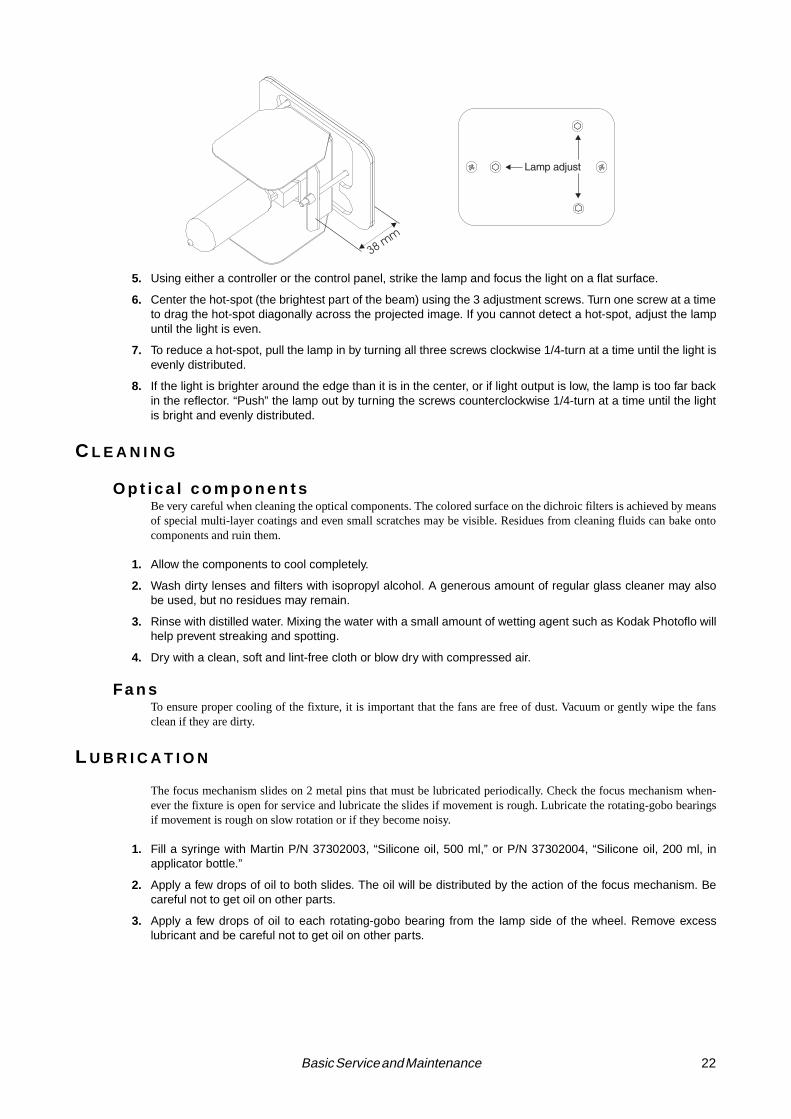
O P T I M I Z I N G L A M P A L I G N M E N T
1. Disconnect the fixture from AC power and allow to cool.
2. Make a preliminary adjustment: remove the lamp assembly and turn the 3 lamp adjustment screws with a 3mm Allen wrench to position the lamp socket plate a distance of 38 mm (1.5”, outside measurement) fromthe access plate as shown below.
3. Replace the lamp assembly.
4. Apply power to the fixture and allow it to reset.
Coa
ted
Gla
ss
:KHQýDQýREMHFWýLVýKHOGýXSýWRýWKHýXQFRDWHGýVLGHñýWKHUHýLVýDýVSDFHýEHWZHHQýWKHýREMHFWýDQGýLWVýUHIOHFWLRQïý7KHýHGJHýRIýWKHýJRERýFDQýEHýVHHQýZKHQýORRNLQJýWKURXJKýWKHýXQFRDWHGýVLGHïý
Coated side towards mirrorUncoated side towards lamp
:KHQýDQýREMHFWýLVýKHOGýXSýWRýWKHýFRDWHGýVLGHñýWKHUHýLVýQRýVSDFHýEHWZHHQýWKHýREMHFWýDQGýLWVýUHIOHFWLRQïý7KHýHGJHýRIýWKHýJRERýFDQQRWýEHýVHHQýZKHQýORRNLQJýWKURXJKýWKHýFRDWHGýVLGHï
Textured side towards mirror
Str
uctu
red
Gla
ss
Smooth side towards lamp
Imag
e G
obos
Correct image towards mirrorReversed image towards lamp
22 Basic Service and Maintenance
5. Using either a controller or the control panel, strike the lamp and focus the light on a flat surface.
6. Center the hot-spot (the brightest part of the beam) using the 3 adjustment screws. Turn one screw at a timeto drag the hot-spot diagonally across the projected image. If you cannot detect a hot-spot, adjust the lampuntil the light is even.
7. To reduce a hot-spot, pull the lamp in by turning all three screws clockwise 1/4-turn at a time until the light isevenly distributed.
8. If the light is brighter around the edge than it is in the center, or if light output is low, the lamp is too far backin the reflector. “Push” the lamp out by turning the screws counterclockwise 1/4-turn at a time until the lightis bright and evenly distributed.
C L E A N I N G
O p t i c a l c o m p o n e n t sBe very careful when cleaning the optical components. The colored surface on the dichroic filters is achieved by meansof special multi-layer coatings and even small scratches may be visible. Residues from cleaning fluids can bake ontocomponents and ruin them.
1. Allow the components to cool completely.
2. Wash dirty lenses and filters with isopropyl alcohol. A generous amount of regular glass cleaner may alsobe used, but no residues may remain.
3. Rinse with distilled water. Mixing the water with a small amount of wetting agent such as Kodak Photoflo willhelp prevent streaking and spotting.
4. Dry with a clean, soft and lint-free cloth or blow dry with compressed air.
Fa n sTo ensure proper cooling of the fixture, it is important that the fans are free of dust. Vacuum or gently wipe the fansclean if they are dirty.
L U B R I C A T I O N
The focus mechanism slides on 2 metal pins that must be lubricated periodically. Check the focus mechanism when-ever the fixture is open for service and lubricate the slides if movement is rough. Lubricate the rotating-gobo bearingsif movement is rough on slow rotation or if they become noisy.
1. Fill a syringe with Martin P/N 37302003, “Silicone oil, 500 ml,” or P/N 37302004, “Silicone oil, 200 ml, inapplicator bottle.”
2. Apply a few drops of oil to both slides. The oil will be distributed by the action of the focus mechanism. Becareful not to get oil on other parts.
3. Apply a few drops of oil to each rotating-gobo bearing from the lamp side of the wheel. Remove excesslubricant and be careful not to get oil on other parts.

23 RoboScan Pro 918
a p p e n d i x a
D M X P RO T O C O L
DMX Channel Start code = 0
DMX1 DMX2 DMX3 DMX4 Value Percent Function
1
Note: If the DMX reset (dRES) and/or DMX lamp off (dLOF) commands are turned off in the menu, they can be enabled by setting color wheel 1 to cyan 401(144-148) and color wheel 2 red 308 (157-160).
0 - 1920 - 4950 - 7273 - 7980 - 99
100 - 119120 - 127128 - 147148 - 167168 - 187188 - 190191 - 193194 - 196197 - 199200 - 202203 - 207208 - 217218 - 227228 - 237238 - 247248 - 255
0 - 78 - 19
20 - 2829 - 3131 - 3939 - 4747 - 5050 - 5858 - 6566 - 7374 - 7575 - 7676 - 7777 - 7878 - 7980 - 8182 - 8585 - 8989 - 9393 - 9797 - 100
Shutter, Strobe, Reset, Lamp On/Off
Shutter closedShutter openStrobe, fastÆslowShutter openOpening pulse, fast ÆslowClosing pulse, fast ÆslowShutter openRandom strobe, fastRandom strobe, mediumRandom strobe, slowShutter openRandom opening pulse, fastRandom opening pulse, slowRandom closing pulse, fastRandom closing pulse, slowShutter openReset fixture, see noteShutter openLamp power on Shutter openLamp power off: time > 5 seconds, see note
20 - 255 0 - 100
DimmerClosed Æ open
3
0 - 1616 - 3232 - 4848 - 6464 - 8080 - 96
96 - 112112 -128128 - 144
145 - 148149 - 152153 - 156157 - 160161 - 164165 - 168169 - 172173 - 176177 - 180181 - 184
185 - 215216 - 245
246 - 255
0 - 66 - 13
13 - 1919 - 2525 - 3131 - 3838 - 4444 - 5050 - 56
57 - 5858 - 6060 - 6162 - 6363 - 6465 - 6666 - 6768 - 6969 - 7171 - 72
73 - 8485 - 96
96 - 100
COLOR 1
Continuous scrollWhite Æ Blue 111Blue 111 Æ Red 301Red 301 Æ Magenta 507Magenta 507 Æ Green 202Green 202 ÆYellow 604Yellow 604 Æ Purple 502Purple 502 Æ Blue 101Blue 101 Æ Pink 312Pink 312 Æ Cyan 401
Fixed color positionsCyan 401Pink 312Blue 101Purple 502Yellow 604Green 202Magenta 507Red 301Blue 111White
Continuous rotationCW, fast Æ slowCCW, slow Æ fast
Enable alternate color functions.

24 DMX Protocol
4
0 - 1616 - 3232 - 4848 - 6464 - 8080 - 96
96 - 112112 -128128 - 144
145 - 148149 - 152153 - 156157 - 160161 - 164165 - 168169 - 172173 - 176177 - 180181 - 184
185 - 215216 - 245
246 - 248249 - 251252 - 255
0 - 255
0 - 66 - 13
13 - 1919 - 2525 - 3131 - 3838 - 4444 - 5050 - 56
57 - 5858 - 6060 - 6162 - 6363 - 6465 - 6666 - 6768 - 6969 - 7171 - 72
73 - 8485 - 96
96 - 9798 - 9899 - 100
0 - 100
COLOR 2: Normal Functions
Continuous scrollWhite ÆCTC 3200-4100CTC 3200-4100 Æ CTC 3200-5600CTC 3200-5600 Æ Blue 104Blue 104 Æ Blue 108Blue 108 Æ Green 206Green 206 Æ Red 308Red 308 Æ Yellow 603Yellow 603 Æ CTC 5500-2900CTC 5500-2900 Æ CTC 5500-4200
Fixed color positionsCTC 5500-4200CTC 5500-2900Yellow 603Red 308Green 206 Blue 108Blue 104 CTC 3200-5600CTC 3200-4100White
Continuous rotationCW, fast Æ slowCCW, slow Æ fast
Random colorFastMediumSlow
Alternate Functions (Channel 3 set from 246 to 255.)
67 different colors in following order: white, purple, pink, magenta, red, orange, yellow, green, cyan, blue, black
5
0 - 55
56 - 7576 - 95
96 - 115116 - 135136 - 155
156 - 175176 - 195196 - 215216 - 235236 - 255
0 - 22
22 - 2930 - 3738 - 4545 - 5353 - 61
61 - 6969 - 7677 - 8485 - 9293 - 100
Rotating Gobo SelectionOpen gobo
Indexing - set position on channel 6Gobo 1Gobo 2Gobo 3Gobo 4Gobo 5
Continuous rotation - set velocity on channel 6 Gobo 5 Gobo 4 Gobo 3 Gobo 2 Gobo 1
6
íýðýìëçìëæ
ìëåýðýëèè
0 - 2 3 - 127
128 - 252253 - 255
íýðýéäèí
èíýðýìíí
íýðýììýðýèíýèíýðýäåääýðýìíí
Rotating Gobo Index and Rotation (Select mode and gobo on channel 5.)
IndexingIndex CCW from defaultDefault indexIndex CW from default
Continuous rotation StaticCW, slow Æ fastCCW, fast Æ slowStatic
DMX Channel Start code = 0
DMX1 DMX2 DMX3 DMX4 Value Percent Function

25 RoboScan Pro 918
7
gMOd = FIX
0 - 910 - 1920 - 2930 - 3940 - 4950 - 5960 - 6970 - 7980 - 89
90 - 102
103 - 119120 - 136137 - 153154 - 170171 - 187188 - 204205 - 221222 - 238239 - 255
0 - 44 - 88 - 11
12 - 1516 - 1920 - 2324 - 2727 - 3131 - 3535 - 40
40 - 4747 - 5354 - 6060 - 6767 - 7374 - 8080 - 8787 - 9394 - 100
Fixed Gobos
Fixed gobo positionsOpen goboGobo 1Gobo 2Gobo 3Gobo 4Gobo 5Gobo 6Gobo 7Gobo 8Gobo 9
Gobo shake, fast ÆÆÆÆ slowGobo 9 Gobo 8 Gobo 7 Gobo 6 Gobo 5 Gobo 4 Gobo 3Gobo 2 Gobo 1
7
gMOd = SCRL
0 - 180
020406080100120140160180
181 - 183184 - 186187 - 189190 - 192193 - 195196 - 198199 - 201202 - 204205 - 207
208 - 231232 - 255
0 - 70
081624313947556370
71 - 7272 - 7373 - 7474 - 7575 - 7677 - 7878 - 7979 - 8080 - 81
82 - 9192 - 100
Fixed GobosContinuous scrollFull positions:Open Gobo 1Gobo 2Gobo 3Gobo 4 Gobo 5 Gobo 6 Gobo 7 Gobo 8 Gobo 9
Gobo shakeGobo 9 shake Gobo 8 shake Gobo 7 shake Gobo 6 shake Gobo 5 shake Gobo 4 shake Gobo 3 shake Gobo 2 shake Gobo 1 shake
Continuous rotationCW, fast Æ slowCCW, slow Æ fast
80 - 255 0 - 100
FocusInfinity Æ 2 meters
9
0 - 199200 - 215216 - 229230 - 243244 - 246247 - 249250 - 252253 - 255
0 - 7878 - 8485 - 9090 - 9596 - 9697 - 9898 - 9999 - 100
Iris
Open Æ closeCloseOpening pulse, fast ÆslowClosing pulse, fast ÆslowRandom opening pulse, fastRandom opening pulse, slowRandom closing pulse, fastRandom closing pulse, slow
DMX Channel Start code = 0
DMX1 DMX2 DMX3 DMX4 Value Percent Function

26 DMX Protocol
10Fixture type = prism (default)
0 - 1920 - 7980 - 89
90 - 149150 - 215
216 - 220 221 - 225226 - 230 231 - 235236 - 240 241 - 245246 - 250 251 - 255
0 - 78 - 31
31 - 3535 - 5859 - 84
84 - 8687 - 8889 - 9091 - 9293 - 9495 - 9696 - 9898 - 100
Prism
Prism outPrism in, CCW rotation, fast Æ slowPrism in, no rotationPrism in, CW rotation, slow Æ fast Prism out
Rotating prism and gobo macrosMacro 1Macro 2Macro 3Macro 4Macro 5Macro 6Macro 7Macro 8
10Fixture type = frost (optional) 0 - 255 0 - 100
Variable Frost1RýIURVWýÆýIXOOýIURVW
110 - 255 0 - 100
Pan Coarse (16-bit MSB)/HIWýÆýULJKWýõìëåý ýQHXWUDOô
- 12 - 120 - 255 0 - 100
Pan Fine (16-bit LSB )/HIWýÆýULJKWý
12 13 12 130 - 255 0 - 100
Tilt Coarse (16-bit MSB)8SýÆýGRZQýõìëåý ýQHXWUDOôý
- 14 - 140 - 255 0 - 100
Tilt Fine (16-bit LSB )8SýÆýGRZQý
- - 13 15
íýðýëýêýðýëéèëéçýðýëéåëéäýðýëèìëèëýðýëèè
íýðýììýðýäçäçýðýäæäåýðýäåääýðýìíí
Pan/Tilt SpeedTracking modeFast Æ slowTracking at slow speed, overrides PTSP FASTTracking at fast speed, overrides PTSP SLOWBlackout while moving
- - 14 16
íýðýëýêýðýëéèëéçýðýëéåëéäýðýëèìëèëýðýëèè
íýðýëýêýðýëéèëéçýðýëéåëéäýðýëèìëèëýðýëèè
0 - 245ëéçýðýëéåëéäýðýëèìëèëýðýëèè
0 - 251252 - 255
0 - 23 - 245
246 - 255
íýðýììýðýäçäçýðýäæäåýðýäåääýðýìíí
íýðýììýðýäçäçýðýäæäåýðýäåääýðýìíí
íýðýäçäçýðýäæäåýðýäåääýðýìíí
íýðýäåääýðýìíí
íýðýììýðýäçäçýðýìíí
Effects Speed
Dimmer, iris, focus and gobo indexing Tracking modeFast Æ slowTracking with shortcuts disabled, overrides SCUT ONTracking with shortcuts enabled, overrides SCUT OFFMaximum speed
Color 1, color 2, and fixed gobo if gMOd = SCRLTracking modeSpeed, fast Æ slowTracking with shortcuts disabled, overrides SCUT ONTracking with shortcuts enabled, overrides SCUT OFFBlackout while moving
Fixed gobo if gMOd = FIXNormal (as set on effect channel), no blackoutNormal, shortcuts disabled, overrides SCUT ONNormal, shortcuts enabled, overrides SCUT OFFBlackout while moving
Rotating gobo and prismNormal (as set on effect channel), no blackoutBlackout while moving
Gobo shake speed if gMOd = SCRLFastSpeed, fast Æ slowFast
DMX Channel Start code = 0
DMX1 DMX2 DMX3 DMX4 Value Percent Function

2
inde
x cc
win
dex
cw
c sc f
clo
sing
230
←24
3
IRIS
ope
n0
clo
se 199
clos
ed2
0021
5o
pen
ing
216
←22
9IRIS
PU
LS
E
o fo s
rand
om
1020
3040
5060
7080
90
019
clo
sed
2049
ope
nS
TR
OB
EO P E N
80
← 9
9
DIM
ME
R P
UL
SE
ope
ning
clos
ing
128
187
RA
ND
OM
ST
RO
BE
me
dsl
ow
RN
D P
ULS
E
217
208
RE
SE
T
237
228
LA
MP
ON
255
248
SH
UT
TE
R
fast
147
148
168
167
LA
MP
OF
F*
O P E N
O P E N
O P E N
OP
EN
50
←72
open
clo
se
f*
100
← 1
1923
824
7
OP
EN
> 5
sec
.22
721
8
128
← c
ontin
uous
ccw
25
23
cont
inuo
us c
w →
127
st
MO
DE
T
EF
FE
CT
S S
PE
ED
216
RO
TA
TIN
G G
OB
O S
EL
EC
TIO
N
156
G 5
175
CH
. 4
A
LT
DIM
ME
R c
lose
d o
pen
CO
NT
INU
OU
S C
OL
OR
SC
RO
LL
(W
HE
EL
1)
whi
teb
lue
111
re
d 30
1 m
age
nta
507
gree
n 20
2 y
ello
w 6
04pu
rple
502
blu
e 1
01pi
nk 3
12
cya
n 40
1
ST
EP
PE
D S
CR
OL
L C
ON
TIN
UO
US
RO
TA
TIO
N
cwcc
w25
524
614
518
5←
215
RN
D
CO
LO
R
CO
NT
INU
OU
S C
OL
OR
SC
RO
LL
(W
HE
EL
2)
whi
te
ctc+
ctc
++
b
lue
104
blu
e 1
08gr
ee
n 20
6re
d 30
8 y
ello
w 6
03ct
c--
ctc
-
0
Alte
rna
te f
unct
ion
(ena
ble
on c
h. 3
) 67
co
lors
: w
hite
, pur
ple,
pin
k, m
age
nta,
red
, ora
nge,
ye
llow
, gr
een
, cya
n, b
lue
, bla
ck
0
OP
EN
127
5676
G 2
G 1
7595
96
G 3
115
116
G 4
135
136
G 5
155
176
195
196
2152
16G
223
523
6G
125
5
ST
EP
PE
D S
CR
OL
L C
ON
TIN
UO
US
RO
TA
TIO
N
cwcc
w
IN
DE
XE
D G
OB
O S
EL
EC
TIO
N
GO
BO
RO
TA
TIO
N
128
255
55
ST
AT
IC G
OB
O S
CR
OL
L (
ST
EP
PE
D)
open
09
G 1
1019
G 2
2029
G 3
30
39
G 4
4049
G 5
50
59
G 6
6069
G 7
7079
G 8
80
89
G 9
901
02
ST
AT
IC G
OB
O S
HA
KE
G
91
0311
9G
812
013
6G
713
715
3G
61
5417
0G
517
11
87G
41
8820
4G
320
52
21G
22
2223
8G
123
925
5
FO
CU
Sin
finity
2 m
eter
s
PR
ISM
out
01919
ccw
rot
atio
n20
←79
sto
p8
089
cw r
ota
tion
out
150
215
MA
CR
OS
12
12
34
56
78
221
226
231
236
241
246
251
PA
Nle
ftri
ght
TIL
T F
INE
(L
SB
)u
pd
own
3 fa
stsl
ow 2
45T
PA
N/T
ILT
SP
EE
D
3 f
dim
mer
, ir
is, f
ocu
s, a
nd
gob
o in
dexi
ng
no c
han
gefix
ed g
obo
s no
ch
ange
rota
ting
pris
m a
nd g
obo
3 co
lors
245
SF«·
»
251
T24
5
0
OP
EN
G 4
G 3
245
0
149
153
157
161
165
169
173
177
181
PA
N F
INE
(L
SB
)le
ftri
ght
TIL
Tu
pd
own
1 3 4 5 6 7 8 9 10
11
1212
1212
1313
-14
14
1315
1416
--
31
42
s
*8
76
43
21
05
216
→24
5
185
←2
1521
6→
245
fms
90→
149
Rob
oSca
n P
ro 9
18 D
MX
Pro
toco
lS
tart
cod
e =
0Im
ple
men
ted
from
CP
U s
oftw
are
ver
sion
1.0
←*
Set c
h. 3
+ c
h. 4
as
sho
wn
to o
verr
ide d
isa
ble
d fu
nct
ion
.T
= t
rack
ing
mo
de (
0-2
& 2
46
-25
1)
S =
no
rma
l pa
n/t
ilt o
r sh
ort
cuts
off
(2
46
-24
8)
F =
fa
st p
an
/tilt
or
sho
rtcu
ts o
n (
24
9 -
25
1)
«·»
= b
lack
ou
t sp
eed
(2
52
-25
5)
← =
va
riab
le s
pee
d, p
oin
ts t
o f
ast
st
←←
←←
←←
←←
←
←
014
41
632
4864
8096
112
128
014
41
632
4864
8096
112
128
fs
2550
7510
012
515
017
520
022
525
0
L I G H T C O L O R G O B O S E F F E C T S P / T
S P E E D
-
TS
TF
TS
TF
TS
TF
«·»
«·»
«·»
pos
itio
n 9
1 2
3 4
5 6
7 8
145
149
153
157
161
165
169
173
177
181
98
7*
43
21
05
ST
AT
IC G
OB
O S
CR
OL
L (
CO
NT
INU
OU
S)
ope
n0
G 1
20G
24
0G
36
0G
480
G 5
100
G 6
120
G 7
140
G 8
160
G 9 18
0
GO
BO
SH
AK
E
CO
NT
INU
OU
S R
OT
AT
ION
cwcc
w20
8←
231
232
→25
59
87
65
43
21
def
ault
opt
ion
al
FR
OS
To
fffu
ll
def
ault
opt
ion
al

28 Error Messages
a p p e n d i x b
E R RO R M E S S AG E S
Display readout Appears if... What to do
LERR (Lamp error) ... the lamp doesn’t ignite within 10 minutes of receiving the ‘Lamp ON’ command. Likely reasons are a missing or defective lamp, or insufficient AC voltage.
• Check the lamp• Check that the voltage and frequency
settings match the local supply.
MERR (Memory error) ...the EEPROM memory cannot be read. • Contact Martin service personnel for assistance.
CSER (Check-sum error) ...a software upload is unsuccessful. • Reload software, see page 19.
**** ... there is no communication between the control panel and motherboard. This read-out appears briefly when switching on the fixture.
• Check fuses and replace accordingly.• Check that cable between control
panel and motherboard is connected properly.
• Reinstall software.
ShER (Short error) ... the fixture detects the lamp is ON but no ‘Lamp ON’ command has been received. This can occur if the lamp relay is stuck or if the lamp feedback circuit fails. The fixture may be operated but remote lamp on/off may be effected.
• Contact Martin service personnel for assistance.
Hot (Hot lamp) ... you attempt to strike the lamp within 8 minutes after having switched it off. The fix-ture will store the ‘Lamp ON’ instruction and strike the lamp once the 8 minute period has elapsed.
• Wait until the lamp strikes.
PTER (PCB temp. error)FTER (FX temperature error)
...there is a malfunction in the PCB or effects section temperature sensing circuit.
• Contact Martin service personnel for assistance.
C1ER (Color wheel 1 time-out)C2ER (Color wheel 2 time-out)FgER (Fixed gobo time-out)RgER (Rot. gobo time-out)
...the magnetic-indexing circuit malfunctions (e.g. sensor defective or magnet missing), or if the effect and/or magnetic sensor requires mechanical adjustment. After the time-out, the effect in question stops in a random position.
• Contact Martin service personnel for assistance.

29 RoboScan Pro 918
a p p e n d i x c
TRO U BL E S H O O T I N G
Problem Probable cause(s) Remedy
One or more of the fixtures is completely dead.
No power to fixture.Check that power is on and cables are plugged in.
Primary fuse blown.See “Changing voltage and frequency settings” on page 18.
Secondary fuse(s) blown.
Filter/power protection fuse blown.
Fixtures reset correctly but all respond erratically or not at all to the controller.
The controller is disconnected from the data link.
Connect controller.
XLR pin-out of the controller does not match pin-out of the first fixture on the link (i.e. signal is reversed).
Install a phase-reversing cable between the controller and the first fixture on the link.
Fixtures reset correctly but some respond erratically or not at all to the controller.
Bad data link connectionInspect connections and cables. Correct poor connections. Repair or replace damaged cables.
Data link not terminated with 120 Ω termination plug.
Insert termination plug in output jack of the last fixture on the link.
Incorrect addressing of the fixtures. Check fixture address and protocol settings.
One of the fixtures is defective and dis-turbs data transmission on the link.
Bypass one fixture at a time until normal oper-ation is regained. Do this by unplugging the XLR in and out connectors and connecting them directly together. Have the fixture ser-viced by a qualified technician.
XLR pin-out on fixtures does not match (pins 2 and 3 reversed).
Install a phase-reversing cable between the fix-tures or swap pins 2 and 3 in the fixture that behaves erratically.
Magnetically indexed effect resets correctly but wanders after fixture reaches operat-ing temperature.
Effect wheel or magnetic sensor requires mechanical adjustment.
Disable effects feedback (page 10). Contact Martin technician for assistance.
No light and “LERR” error message displayed.
The ballast and transformer settings do not match local AC voltage and frequency.
Disconnect fixture. Check ballast and trans-former settings and correct if necessary.
Lamp blown Disconnect fixture and replace lamp.
Lamp not installed Disconnect fixture and install lamp.
Lamp cuts out intermittently.Fixture is too hot.
Allow fixture to cool.Reduce ambient room temperature.Recalibrate temperature sensors.
The ballast and transformer settings do not match local AC voltage and frequency.
Disconnect fixture. Check ballast and trans-former settings and correct if necessary.

30 Circuit Board Layout
a p p e n d i x d
C I RC U I T B O A RD L AYO U T
RE
D
BR
OW
N
Hard boot jumper
XLR pin-out jumper
Lamp feedback

31 RoboScan Pro 918
a p p e n d i x e
S P E C I F I C A T I O N S
P hy s i c a l• Dimensions without mounting bracket (LxWxH):....................................... 795 x 330 x 308 mm (31.3 x 13.0 x 12.1 in)• Weight, EU version.................................................................................................................................32.5 kg (71.5 lbs)• Weight, US version.................................................................................................................................36.5 kg (80.5 lbs)
E l e c t r i c a l , E U v e rs i o n• Voltage taps (ballast) ................................................................................ 200/230/245 V @ 50 Hz; 208/227 V @ 60 Hz• Power and current..............................................................................................................695 W, 3.8 A @ 230 V / 50 Hz• Power factor (PF)......................................................................................................................................................... 0.79
E l e c t r i c a l , U S v e rs i o n• Voltage taps (transformer) ...............................................................................................100/120/230/250 V @ 50/60 Hz• Power and current.................................................................................................................790 W, 8 A @ 120 V / 50 Hz• Power factor (PF).............................................................................................................. 0.79 @ 50 Hz, > 0.79 @ 60 Hz
F u s e s• Main fuse, fixture wired at 200 V or higher .......................................................6.3 A / 250 V time delay, P/N 05020020• Main fuse, fixture wired at 100 or 120 V (US version only)...............................10 A / 250 V time delay, P/N 05020025• Fuse F601 ..........................................................................................................5.0 A / 250 V time delay, P/N 05020018• Fuse F602 ...........................................................................................................4.0 A / 250 V time delay, P/N 05020016• Fuse F603 .......................................................................................................0.315 A / 250 V time delay, P/N 05020004• AC filter and power protection fuse ...................................................... 2.0 A / 250 V special fast-acting, P/N 05021010
P h o t o m e t r i c p e r fo r m a n c e• Light output ...........................................................................................................................................................8500 lm• Center intensity, 17° version............................................................................................................................. 234,000 cd• Center intensity, 23.5° version.......................................................................................................................... 127,000 cd
R o t a t i n g g o b o s• Outside diameter....................................................................................................................................... 27.8 +/- 0.2 mm• Maximum image diameter.......................................................................................................................................23 mm• Maximum thickness ..................................................................................................................................................4 mm• Recommended custom glass gobo thickness: ........................................................................................................1.1 mm• Recommended custom glass gobo coating:..................................................................... dichroic or enhanced aluminum• Recommended custom gobo glass: ........................................................................ high temperature, Borofloat or better
T h e r m a l• Maximum ambient temperature ................................................................................................................ 40° C (104° F)• Surface temperature under normal conditions............................................................................................ 80° C (176° F)
A c c e s s o r i e s a n d s e l e c t e d s p a r e p a r t s• Osram HSR-575/2 (575 W, 85 lm/W, 1000 h avg. life, 6000K)................................................................. P/N 97010200• Philips MSD-575 (575 W, 75 lm/W, 2000 h avg. life, 5700K) .................................................................. P/N 97010202• Philips MSR-575/2 (575 W, 85 lm/W, 1000 h avg. life, 6100K) ............................................................... P/N 97010201• Single unit flight case ..................................................................................................................................P/N 91505006• Double unit flight case ................................................................................................................................P/N 91505007• Half-coupler clamp......................................................................................................................................P/N 91602005• G clamp .......................................................................................................................................................P/N 91602003• MPBB1 Uploader ........................................................................................................................................P/N 90758410• 4 Channel Opto-Isolated RS-485 Splitter/Amplifier...................................................................................P/N 90758060• Retention spring for rotating-gobo holder...................................................................................................P/N 17760040• Frost filter for MAC 500/RS 918, assembled..............................................................................................P/N 91611003• Rotating-gobo holder...................................................................................................................................P/N 17320090• Retention spring for rotating gobo ..............................................................................................................P/N 17760210


![918 todd[1]](https://img.pdfslide.us/doc/110x75/55d713f6bb61eb81548b46c7/918-todd1.jpg)