Embed Size (px)
Citation preview

Source of Acquisition NASA Johnson Space Center
Robonaut: A Robotic Astronaut Assistant
M.A. Diftler Lockheed Martin
Automation and Robotics Department Mail Code C35
Houston, TX 770058 [email protected]
Keywords Humanoids, dexterous robots, anthropomorphic, space manipulator, redundant system,
mechatronics.
Abstract NASA's latest anthropomorphic robot, Robonaut, has
reached a milestone in its capability. This highly
dexterous robot, designed to assist astronauts in space, is
now performing complex tasks at the Johnson Space
Center that could previously only be carried out by
humans. With 43 degrees of freedom, Robonaut is the
first humanoid built for space and incorporates
technology advances in dexterous hands, modular
manipulators, lightweight materials, and telepresence
control systems. Robonaut is human size, has a three
degree of freedom (DOF) articulated waist, and two,
seven DOF arms, giving it an impressive work space for
interacting with its environment. Its two, five fingered
hands allow manipulation of a wide range of tools . A
pan/tilt head with multiple stereo camera systems
provides data for both teleoperators and computer vision
systems.
1 Introduction The requirements for extra-vehicular actIVIty (EVA)
on-board the International Space Station (ISS) are
expected to be considerable. These maintenance and
construction activities are expensive and hazardous.
Astronauts must prepare extensively before they may
leave the relative safety of the space station, including
pre-breathing at space suit air pressure for up to 4 hours.
R.O. Ambrose NASA Johnson Space Center
Automation, Robotics and Simulation Division Mail Code ER4
Houston Texas 77058 rambrose @ems.jsc.nasa.gov
Once outside, the crew person must be extremely
cautious to prevent damage to the suit.
Certain pieces of the Space Station Alpha have been
designed to be serviced by robotic systems. The
Canadian Space Agency 's Special Purpose Dexterous
Manipulator (SPDM) was developed for this purpose
such system. To be serviceable by the SPDM, worksites
have been designed to have different approach corridors
than EVA and specialized interfaces.
Figure 1. Robonaut
While specialized worksites for robotics systems have
been very successful in a variety of industries, including
space, the Robotic Systems Technology Branch at the
NASA Johnson Space Center (JSC) is taking a different

approach to building service robots for space; developing
robots to work with existing human interfaces. This is
Robonaut's niche in the international space manipulator
family. It can work in the same corridors as the crew, use
a significant subset of the Extra-Vehicular Activity
(EVA) tool set, and is designed to work alongside a crew
person safely. Additionally, Robonaut can serve as a
minuteman, providing mission controllers with a highly
dexterous device for dealing with an EVA emergency in
far less time than the several hours it takes to prepare an
astronaut for a space walk.
2 Robonaut System Overview The focus of the Robonaut team has been in the design
and construction a dexterous upper extremity. However,
Robonaut has recently transitioned from a single hand
and arm with a fixed shoulder to a dual limbed upper
body with an articulating three degree-of-freedom (DOF)
waist. This results in a total of 43 DOF dexterous robot
(figure 1).
St~eo Vision Helmet 200FNeck RMS lola-face Arms
Shoulder Elbow Wrist Hand
Body Backpack Leg
Ilip Knee Ankle
ISS Load Limiter WlFF "Stinger"
Figure 2. Robonaut in Og Configuration
While working during EVA, crew members typically
place both legs into a portable foot restraint. In its space
configuration, Robonaut uses the same interface with a
single seven DOF leg. The end effector of this leg uses
the same interface as the crew's foot restraints and plugs
into sockets around Space Station . Having a leg provides
Robonaut with the ability to anchor itself at worksites
and provides a great amount of body mobility once
anchored. Figure 2 shows a representation of Robonaut
in its space configuration.
Beyond having the correct anatomy to work with EVA
equipment, the Robonaut system is designed with space
operations in mind. During the design phase, the ability
to work in space was considered for nearly every aspect,
including materials selection, thermal endurance,
lubricants , avionics, and computer selection.
Robonaut is currently a teleoperated system. The
anthropomorphic form of Robonaut allows a very
intuitive mapping between human and robot. By
incrementally augmenting the teleoperation capabilities,
the goal is to lighten the teleoperator's load by
transitioning to a more supervisory role.
Figure 3. The Robonaut Hand
3 Hands Robonaut's hands set it apart from any previous space
manipulator system. These hands can fit into all the same
places currently designed for an astronaut's gloved hand.
A key feature of the hand is its palm degree of freedom
that allows Robonaut to cup a tool and line up its long
axis with the roll degree of freedom of the forearm,
thereby, permitting tool use in tight spaces with
minimum arm motion. Each hand assembly shown in
figure 3 has a total of 14 DOFs, and consists of a forearm,
a two DOF wrist, and a twelve DOF hand complete with
position, velocity, and force sensors. The forearm, which
measures four inches in diameter at its base and is
approximately eight inches long, houses all fourteen
motors, the motor control and power electronics, and all
of the wiring for the hand . An exploded view of this
assembly is given in figure 4. Joint travel for the wrist
pitch and yaw is designed to meet or exceed that of a
human hand in a pressurized glove.

Figure 4: Forearm Assembly
The requirements for interacting with planned space
station EVA crew interfaces and tools provided the
starting point for the Robonaut Hand design [1]. Both
power and dexterous grasps are required for
manipulating EVA crew tools. Certain tools require
single or multiple finger actuation while being firmly
grasped. A maximum force of 20 Ibs and torque of 30
in-Ibs are required to remove and install EVA orbital
replaceable units (ORUs) [2].
The hand itself consists of two sections (figure 5) : a
dexterous work set used for manipulation, and a grasping
set which allows the hand to maintain a stable grasp
while manipulating or actuating a given object. This is
an essential feature for tool use [3]. The dexterous set
consists of two 3 DOF fingers (index and middle) and a
3 DOF opposable thumb. The grasping set consists of
two, single DOF fingers (ring and pinkie) and a palm
DOF. All of the fingers are shock mounted into the palm.
In order to match the size of an astronaut's gloved hand,
the motors are mounted outside the hand, and mechanical
power is transmitted through a flexible drive train . Past
hand designs [4,5] have used tendon drives which utilize
complex pulley systems or sheathes, both of which pose
serious wear and reliability problems when used in the
EVA space environment. To avoid the problems
associated with tendons, the hand uses flex shafts to
transmit power from the motors in the forearm to the
fingers. The rotary motion of the flex shafts is converted
to linear motion in the hand using small modular
leadscrewassemblies. The result is a compact yet rugged
drive train.
Oraspin& F"""' __ ~_"""III
Tmmb
Figure 5: Hand Anatomy
Overall the hand is equipped with forty-two sensors (not including tactile sensing). Each joint is equipped with
embedded absolute position sensors and each motor is
equipped with incremental encoders. Each of the
Ieadscrew assemblies as well as the wrist ball joint links
are instrumented as load cells to provide force feedback.
In addition to providing standard impedance control ,
hand force control algorithms take advantage of the
non-backdriveable finger drive train to minimize motor
power requirements once a desired grasp force is
achieved. Hand primitives in the form of pre-planned
trajectories are available to minimize operator workload
when performing repeated tasks.
4 Arms, Neck and Waist Robonaut's arms, neck and waist are human scale
manipulators designed to fit within EVA corridors.
Beyond its volume design, these appendages have human
equivalent strength, human scale reach, thermal
endurance to match an eight hour EVA, fine motion, high

bandwidth dynamic response, redundancy, safety, and a
range of motion that exceeds that of a human limb. Both
the arms and waist have a dense packaging of joints and
avionics developed with the mechatronics philosophy.
The endoskeletal design of the arm and waist house
thermal vacuum rated motors, harmonic drives, fail-safe
brakes and 16 sensors in each joint. The arm's small size,
1: 1 strength to weight ratio, density, and thermal vacuum
capabilities make it the state-of-the-art in space
manipulators today (figure 6).
Figure 6: Robonaut Arm
Robonaut has four serial chains emerging from the body:
two upper arms for dexterous work, a neck for pointing
the head, and a leg for stabilizing the body in micro
gravity. These chains are all built with common
technology, best described as a family of modular joints,
characterized by size and kinematic motion type. There
are three torque ranges, from 10 ft-lbs to 200 ft-lbs, and
two motions types, roll and pitch. Other scales have been
built for thermal vacuum testing, but are not included in
the currently integrated system.
Figure 7. Arm Design Visualization Tool
~-.-.~.--- ---- --- ----
A software design tool, with visualization shown in
Figure 7, was developed at JSC for use in trade studies of
kinematic arrangements [6] , strength [7] and thermal
analyses [8]. Using a database of drive train components,
optimized sizing of the manipulator joints was achieved
with identification of thermal endurance [9] and task
workspace suitability [10]. Of particular interest is the
choice of a bifurcating system, where a central , and
articulated chain, here the segment from ankle to body,
splits into two independent upper arms. This waist
mobility has been shown to complement the dexterity of
a dual arm system, by allowing the intersection of the
two arm's dexterous workspaces to be repositioned
around a work site. This enables the use of smaller,
closely configured arms to perform dexterous
manipulation over a large resultant workspace. Figure 8
shows the coordination of a waist bending motion with
an arm's reach , expanding the arm's reachable
workspace. The intersection of the arm 's dexterous
region is a toroidal space centered on the line of action
passing through the two shoulders, which is then in turn
swept by the waist motion for a spherical dexterous
workspace of the full system, shown schematically in
Figure 9.
Figure 8: Workspace with Waist Motion
The common joints that make up the waist, arms and
neck use a torque based control law at the lowest level
taking advantage of embedded strain gauges. Better than
a 20HZ bandwidth is available at this level. Higher level
position loops wrap around the torque controller to
provide impedance control at the joint level.
-I
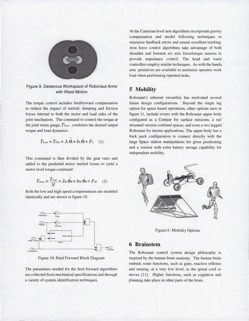
Figure 9. Dexterous Workspace of Robonaut Arms with Waist Motion
The torque control includes feedforward compensation
to reduce the impact of inertial , damping and friction
forces internal to both the motor and load sides of the
joint mechanism. The command to control the torque at
the joint strain gauge, T Scmd , combines the desired output
torque and load dynamics.
This command is then divided by the gear ratio and
added to the predicted motor inertial losses to yield a
motor level torque command:
Both the low and high speed compensations are modeled
identically and are shown in figure 10.
Figure 10: Feed Forward Block Diagram
The parameters needed for the feed forward algorithms
are collected from mechanical specifications and through
a variety of system identification techniques.
At the Cartesian level arm algorithms incorporate gravity
compensation and model fo llowing techniques to
minimize feedback errors and ensure excellent tracking.
Arm force contro l algorithms take advantage of both
shoulder and forearm six axis force/torque sensors to
provide impedance control. The head and waist
controllers employ similar techn iques. As with the hands,
arm primitives are available to minimize operator work
load when performing repeated tasks.
5 Mobility Robonaut's inherent versati li ty has motivated several
future design configurations. Beyond the single leg
option for space based operations, other options seen in
figure 11 , include rovers with the Robonaut upper body
configured as a Centaur for surface missions, a rail
mounted version confined spaces, and even a two legged
Robonaut for terrain applications. The upper body has a
back pack configuration to connect directly with the
large Space station manipulators for gross positioning
and a version with extra battery storage capability for
independent mobility.
Figure11: Mobility Options
6 Brainstem The Robonaut control system design philosophy is
inspired by the human brain anatomy. The human brain
embeds some functions, such as gaits, reactive reflexes
and sensi ng, at a very low level , in the spinal cord or
nerves [11]. Higher functions, such as cognition and
planning take place in other parts of the brajn.
-

Within the Robonaut control system, the functions
analogous to the very low level functions in the brain are
referred to as the brainstem. The brainstem contains the
joint and Cartesian controllers for the 43 DOF, sensing,
safety functions, and low level sequencing.
Using the brainstem approach allows higher level
functions to operate independently of the low level
functions. This allows the Robonaut system to
implement a variety of control methods ranging from
teleoperation to full autonomy with the brainstem
unaware of which higher level control system is being
used . An application programmer's interface (API)
separates the brainstem from the higher level systems. This standard interface allows systems to both monitor
and modify the state of the Robonaut brainstem.
As a humanoid robot designed for the purpose of
working with humans in space, safety is the central to
Robonaut's control system. By embedding safety
systems at a low level in the brainstem overall safety and
performance are improved [12].
The computing environment for Robonaut utili zes the
PowerPC processor. This processor was selected for
both performance and its heritage in space flight. The
processor's and 110 connect across a VME bus and use
the VxWorks™ real-time operating system. Robonaut's
brainstem software is written using the ControlshelJTM
development environment. Controlshell provides a
graphical interface that enforces object-oriented design
and the re-use of code. The flexibility and performance
of these systems make for an exceptional controls
development environment.
7 Operational Modes Currently, Robonaut's primary mode of operation is
through a telepresence control system. As shown In
figure 12, when wearing the Virtual Reality gloves, and a
helmet, an operator's hands, arms and neck are mapped
directly to the Robonaut system. Sensors in the gloves
determine the operator's hand position, creating a
command for the Robonaut hand. The neck, arm and
waist commands are generated using six-axis Polhemus
sensors mounted to the operator's helmet, wrist and chest,
respectively. The scale and proportions of the Robonaut
anatomy are very human like, allowing for the use of
everyday experience, instincts and training to be applied
to teleoperated tasks . Novice operators are able to
demonstrate proficiency with less than five minutes of
immersion.
Figure 12: Telepresence Control Gear
More shared control, leading to enhanced autonomy for
Robonaut is in work. The hand and arm primitives noted
above are the building blocks that are being used to add
the first automatic modes into Robonaut's control system.
The API allows both in-house and external artificial
intelligence developers to integrate task planners, vision
based grasping systems, and learning algorithms. The
goal is to give Robonaut's supervisor a combination of
autonomous and telepresence control modes to
accomplish complex tasks.
8 Task Experiments In its current teleoperation mode, Robonaut can perform
a wide variety of space, surface and, tool usage tasks.
Space tasks include tether hooks used as lifelines by
astronauts during EVA and power drills representing
torque tools. Surface tasks include scooping gravel and
transferring it into containers. Robonaut also can work
with a wide variety of tools, including wire strippers,
socket wrenches, and flashlights.
Adding a second arrnlhand and waist has added another
dimension to Robonaut 's capabilities. Instead of being
forced to be handed tools by a human in a very limited

'---
range, Robonaut is now capable of picking up tools at
one area and re-positioning its waist to operate at the
worksite. The addition of the second arm and hand
allows for Robonaut to perform two handed tasks . For
example, Robonaut has worked with EVA hand rail s,
connected network cables, and worked with soft goods
boxes. Robonaut performing two handed tasks are
shown in figures 13 and 14 ..
Figure 13. Robonaut Manipulating Simulated Martian
Gravel(L) and Threading a Nut onto a Bolt(R).
Figure 14: Robonaut Attaching a Tether Hook(L) and
Tying a Knot in a Rope(R).
9 Conclusions and Future Challenges Robonaut subsystems development is an ongoing
process. Arm and hand designs are continuing to push the
state of the art in packaging, strength, and sensor count.
Avionics are becoming smaller and better integrated
leading to a true mechatronic design. The teleoperation
interface is becoming even more intuitive for the operator,
enabling more complex tasks. The common
denominator for these technologies is the upper body
dexterous system, which continues to be the team's
development focus. Having started with this portion of
the humanoid system, we continue to advance its
dexterity while seeking specific lower body options
optimized for new missions .
References [1] Lovchik, C.S., and Diftler, M. A., ''The Robonaut
Hand: a Dexterous Robot Hand for Space",
Proceedings of the IEEE International Conference on Robotics and Automation, Detroit, Michigan,
907-912, 1999.
[2] Extravehicular Activity (EVA) Hardware Generic
Design Requirements Document, JSC 26626,
NASA/Johnson Space Center, Houston, Texas,
July, 1994.
[3) Jau , B., Dexterous Tele-manipulation with Four
Fingered Hand System. Proceedings of the IEEE
International Conference on Robotics and
Automation,. Nagoya, Japan, 338-343 ,1995. [4] Jacobsen, S., et ai., Design of the UtahIM.I.T.
Dexterous Hand. Proceedings of the IEEE
International Conference on Robotics and
Automation, San Francisco, CA, 1520-1532, 1986.
[5] Salisbury, J . K. , & Mason, M. T., Robot Hands and
the Mechanics of Manipulation. MIT Press, Cambridge, MA, 1985.
[6] Ambrose, Robert 0. , "Interactive Robot Joint
Design, Analysis and Prototyping" , IEEE 95
Robotics and Automation Conference, Nagoya,
Japan, May 1995.
[7] Ambrose, Robert 0., Diftler, M. A., "The
Minimum Form of Strength in Serial, Parallel and
Bifurcated Manipulators", IEEE Robotics and
Automation Conference, Leuven Belgium, 1998. [8) Ambrose, Robert O. and Berka, R. B., "Thermal
Management in Hyper-Redundant Space
Manipulators", SPIE Cooperative Intelligent
Robotics in Space IV, September 1993.
[9] Ambrose, Robert O. and Tesar, D. , "The Optimal
Selection of Robot Modules for Space
Manipulators" , Space '94, Albuquerque NM,
February, 1994.

[lOJ Ambrose, R.O. and Diftler, M.A., "Definitions of
Strength in Serial and Bifurcated Manipulators",
[SA Conference, November 1996, Chicago II. [IIJ Albus, J. , A Theory of Cerebellar Function.
Mathematical Biosciences, 10 (1971) 25-61
[12] Aldridge, H. , Bluethmann, w., Ambrose, R.,
DiftJer, M. , Control Architecture for the Robonaut
Space Humanoid, Proceedings, Humanoids 2000,
The 1st lEEE-RAS Conference on Humanoid
Robots, Cambridge, MA 2000.

![Robonaut Mobile Autonomy: Initial Experiments...Robonaut systems (figure 1) are the first humanoids specifically designed for space [9]. They incorporate technology advances in dexterous](https://img.pdfslide.us/doc/110x75/60ff83042851357e640233b5/robonaut-mobile-autonomy-initial-experiments-robonaut-systems-figure-1-are.jpg)


![[Challenge:Future] Modern Astronaut](https://img.pdfslide.us/doc/110x75/58f0925f1a28abb3148b45ef/challengefuture-modern-astronaut.jpg)


