Embed Size (px)
Citation preview

Abstract : Interceptor 1.4 is a boat that’s designed by roboboat team from Universitas Diponegoro, Indonesia. It uses SWATH (Small Waterplan Area of Twin Hull) for its hull to reduce resistance that’s generated by hull form. It has propulsor for each cylinder body that can improve manuveribility so that this boat can reach all the mission that’s challanged by comitte. System of this boat uses two modes, they are autonomous system and manual system which is completed by sensor, controller, and electrical component to compate in the annual competition in Virginia Beach by association Unmanned Vehicle Systems International (AUVSI) 2014.
I. Introduction Autonomous vehicle have purpose to help human. The Autonomous Surface Vehicle (ASV) have main purpose to build a autonomous watercraft robot . This ASV project is for international competition in Virginia Beach. This ASV project or Interceptor 1.4 uses. Controller, various sensor and programs of DiBoat 1.1 to make this boat can navigate in autonomous. Additionaly, it possesses a radio control backup system in case the vehicle become lost, allowing it to be manually controlled back to base port.
2. Detailed Design Description 2.1 Background Design Autonomous is a system that has ability to do a complex task without human interaction. Interceptor 1.4 is the boat using SWATH (Small Waterplan Area of Twin Hull) for it’t hull. It’s completed by censor, program, and electrical control to make this boat can navigate autonomously to pass the mission. User only manage this boat with remote control when this boat is loss control and drive it into jetty. Generaly, interceptor 1,4 consist of three division, they are design, mechanical, and electrical division. This boat uses swath system for its hull so that this boat can sail faster and has good stability. From this design, this boat has a large deck opening used to manage electrical component. This boat has various censor such as camera,pinger detected,gps and compass DESIGN HARDWARE 2.2 Linesplan Determination for design and dimension based on ship comparation methode. We find out the boat that has similar form and dimension then we scale it into real dimension as we need. Linesplan of this vessel are as follows :
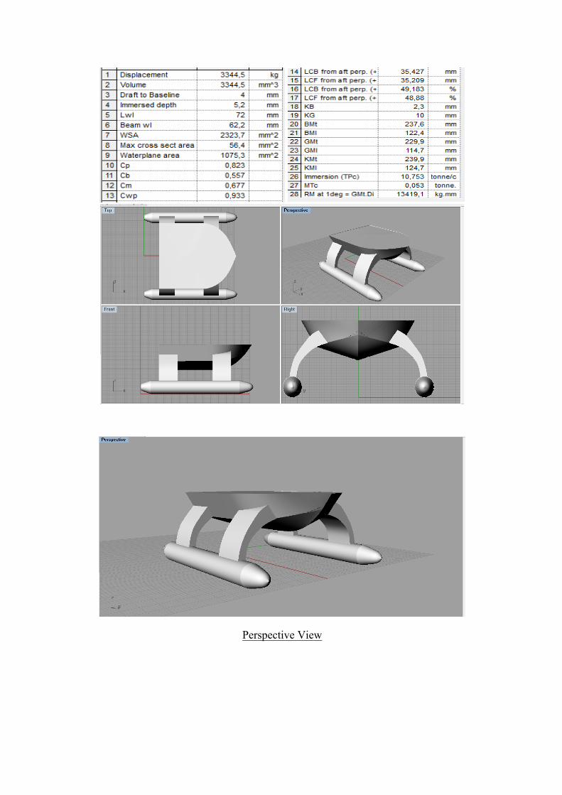
Perspective View
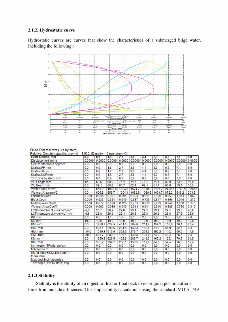
2.1.2. Hydrostatic curve
Hydrostatic curves are curves that show the characteristics of a submerged bilge water. Including the following :
2.1.3 Stability
Stability is the ability of an object to float or float back to its original position after a force from outside influences. This ship stability calculations using the standard IMO A. 749
0
1
2
3
4
5
6
7
8
9
0 0 0 0 0 0 0 0 0 0
0 500 1000 1500 2000 2500 3000 3500 4000 4500
-10 -5 0 5 10 15 20 25 30 35
0 0,5 1 1,5 2 2,5 3 3,5 4 4,5
0 250 500 750 1000 1250 1500 1750 2000 2250
0 100 200 300 400 500 600 700 800 900
0 0 0 0 0 0 0 0 0 0
0 0 0 0 0 0 0 0 0 0
Disp.
Wet. Area
WPA
LCB
LCF
KB
KMt
KML
Immersion (TPc)
MTc
Displacement tonne
Draft m
m
Area mm^2
LCB, LCF from zero pt. (+ve fw d) mm
KB mm
KMt mm
KML mm
Immersion tonne/cm
Moment to Trim tonne.m

-2
-1,5
-1
-0,5
0
0,5
1
1,5
2
0 40 80 120 160
Max GZ = 1,126 m at 20 deg.
3.1.2.4: Initial GMt GM at 0,0 deg = 5,858 m
Heel to Starboard deg.
GZ
m
(18) ch 3, with the maximum stability Arm (GZ max) is 1.126 meters, the maximum stability occurs at arm tilt angle of 20
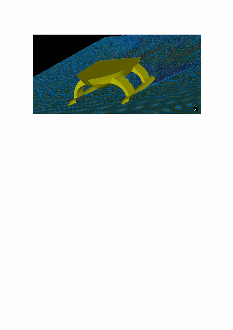
2.1.4 Resistance
The method used for this analysis is a slender body, by knowing the resistance vessels, we can know the power that is used in order to meet the desired speed:

Software Design
The software used as the boat artificial intelligence is built on top of C# .NET Framework.
The Platform itself is a desktop application so it can easily deployed on PC. A scenario editor
provided in the program’s interface, was designed to help the end-user configure the boat
behavior for any circumstances based on the constrain of each mission.
1. Vision
The software implement AFORGE.NET libraries to help the boat recognize the
environment. These library use the Euclidean Color Filtering to distinguish the color
of the buoy which is used as the reference of navigation heading in the speed gates
and the first mission. To keep the track of red and green buoy, the system uses one
camera (hereinafter referred to as gate viewer) for each of those buoys. Each camera
is attached with a servo to mobilize the camera heading and the algorithm will
maintain camera view to focus on a buoy. The action of algorithm maintaining the
camera heading, result in the angle production of servo’s rotation, which will be
gathered as boat’s heading data relative to the gates. As the route of first mission is
filled by colored obstacles, a camera located at the prow (hereinafter referred to as
obstacle viewer) is utilized by the software provide a color array to save the value of
every color used as the obstacle buoy color. The algorithm will produce a warning if
there is obstacle on safe area, and execute the appropriate action of the corresponding
detection. The gate viewer will also recognize polygon in docking mission.
2. Navigation
The software calculate the GPS data from Arduino (which is defined as current
location data) and the one that saved on program’s memory (which is defined as
desired location data), to create the boat’s desired heading using Haversine formula.
An error of heading will be calculated by finding the difference between current
heading and desired heading. As mentioned before, the angle of servo’s rotation will
be calculated to produce desired heading which is only used in first mission, the
obstacle avoidance.

A. Electrical system
According to the last year design we make an improvement, in software and
hardware. But the improvement still make the system simple and powerfull. Because with
simple system we avoid the error caused by complexity algorithm. Just make a effective and
efficient design.
The laptop Lenovo thinkpad yoga with processor Intel Core i5-4200U and RAM 4GB
DDR3 has been chosen as the main processor. The main processor will calculate the data of 3
camera (webcam Logitech C270 with servo, 2 camera moves and 1 camera static) to get
buoys position and convert it to the control signal throttle and rudder. The control signal will
be transferred to the control board (Arduino Mega) microcontroller board based on the
ATmega1280 It has 54 digital input/output pins (of which 14 can be used as PWM outputs),
16 analog inputs, 4 UARTs (hardware serial ports), a 16 MHz crystal oscillator, a USB
connection, a power jack, an ICSP header, and a reset button. It contains everything needed
to support the microcontroller; simply connect it to a computer with a USB cable or power it
with a AC-to-DC adapter or battery to get started. The main processor also have to finished
the TCP/IP task by using the internal wireless module, acquired GPS data and get the heat
data.
A.1 Cooling System
The new ship’s body has a new cooling system that is much more efficient than the system
that was used in previous years. This new cooling system consists of two fans, similar to last
years, except the fans are located on the end of the box instead of the top. Another major
difference is,
both fans are facing the same direction, to double the airflow. The airflow now goes in the
forward facing side of the box and out the rear facing side. This box has slits along the rear
facing side to allow the hot air escape from the box. We also oriented the internal
components of the box so that they would not block any airflow through the box.
A.2 Power
Two Lipoly Battery use for our robot. Turnigy Nanotech 3S use as the supply voltage of the
brushed and Turnigy Nanotech 2S use as the supply voltage of the others. We use separate
supply voltage to avoid the error caused by lack of voltage. The brushed motor itself can

drain the battery rapidly. So, if we joint the voltage source, it will be used up rapidly and will
be lack of energy in controller series which is cause controller series become error.
A.3 Sensory and Servo
A.3.1 Camera (Webcam Logitech)
We used 3 webcam Logitech C270 as our main vision sensor, which uses the RGB color
space for data output. The Logitech C270 is capable of 3 mega-pixel resolutions for video
output. The camera resolution is scaled down to 640x480 pixels to enhance processing speed
and reduce computational power requirements. The resolution of the camera controls the
amount of video frames per second that can be processed. Since pixels are processed in a
matrix form, the more pixels, the longer processing time required for each frame.
A.3.2 DS04-NFC 360°
This is a continuous rotation DC servo gear motor. Comes with a package of mounting
hardware and cranks/pivot arms.
Specifications:
• Weight: 38g (grams) • Size: 40.8mm x 20mm x 39.5mm • Torque: @4.8vDC 5.5kg/cm • Speed: @4.8vDC 0.22sec/60° • Current draw:under 1 amp

A.3.3 GPS Module APM2.5 NEO-6M
Cost effective, high-performance u-blox 6 based NEO-6 series of GPS modules, that
brings the high performance of the u-blox 6 positioning engine to the miniature NEO form
factor. The module will automatically fix its gps position and output positioning information
via its serial port with no configuration.
These receivers combine a high level of integration capability with flexible connectivity
options in a small package. This makes them perfectly suited for mass-market end products
with strict size and cost requirements.
Specification:
• GPS module, 3 v - 5 v power supply general
• Ublox NEO - 6 m module cabin with ceramic is predestined friends the antenna, the
signal is strong
• Take the data backup battery
• Take data off electric storage EEPROM
• Antenna size and * 22 mm
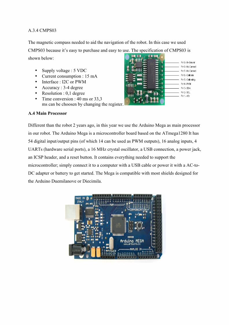
A.3.4 CMPS03
The magnetic compass needed to aid the navigation of the robot. In this case we used
CMPS03 because it’s easy to purchase and easy to use. The specification of CMPS03 is
shown below:
• Supply voltage : 5 VDC • Current consumption : 15 mA • Interface : I2C or PWM • Accuracy : 3-4 degree • Resolution : 0,1 degree • Time conversion : 40 ms or 33,3
ms can be choosen by changing the register.
A.4 Main Processor
Different than the robot 2 years ago, in this year we use the Arduino Mega as main processor
in our robot. The Arduino Mega is a microcontroller board based on the ATmega1280 It has
54 digital input/output pins (of which 14 can be used as PWM outputs), 16 analog inputs, 4
UARTs (hardware serial ports), a 16 MHz crystal oscillator, a USB connection, a power jack,
an ICSP header, and a reset button. It contains everything needed to support the
microcontroller; simply connect it to a computer with a USB cable or power it with a AC-to-
DC adapter or battery to get started. The Mega is compatible with most shields designed for
the Arduino Duemilanove or Diecimila.

A.5 Motor Driver
In this year our robot use 2 motor brused DC and then for the motor driver we use EMS
(Embedded Module Series) 30 A H-Bridge H-Bridge driver is designed to generate two-way
drive with a continuous current to 30 A at a voltage of 5.5 Volts to 16 Volts. Equipped with a
load current sensor circuit that can be used as feedback to the controller. This module is able
to drive inductive loads such as DC motors, stepper motors, relay coils, selenoida, and other
expenses. Dimensions: 7.4 cm (p) x 6.1 cm (l) x 1.9 cm (t).
specifications:
- Consisting of a full H-Bridge driver. (IC VNH2SP30 features the current sense).
- Drivers capable of passing continuous current 30 A and support the load voltage from 5.5 V
to 36 V (IC VNH2SP30 only up to 16V).
- Input compatible with TTL and CMOS voltage levels.
- Output tri-state.
- The output MOSFET with low drain-source resistance (typ. 0.034 ohm).
- Supports PWM control with a frequency of up to 20 Khz.
- Fault detection.
- Short-circuit protection and overtemperature protection.
- Undervoltage and overvoltage shutdown.
- Reverse battery protection.
- Line power supply input (logic) separate from the power supply line to the load.