Embed Size (px)
Citation preview
March 2002
Road Planning and Design Manual Chapter 20: Roadside Amenities
20Chapter 20
RoadsideAmenities
March 2002
Chapter 20: Roadside Amenities Road Planning and Design Manual
20
Table of Contents20.1 General Introduction 20-1
20.1.1 Strategic Framework 20-120.2 Service Centres 20-2
20.2.1 Introduction 20-220.2.2 Service Centre Strategy 20-220.2.3 General Requirements for Service Centres 20-320.2.4 Specific Facility Requirements 20-320.2.5 Access 20-3
20.3 Rest Areas 20-420.3.1 Introduction 20-420.3.2 Rest Area for Motorists 20-520.3.3 Heavy Vehicle Rest Area 20-520.3.4 Combined Rest Areas 20-620.3.5 Towns as Rest Areas 20-620.3.6 Camping at Rest Areas 20-620.3.7 Distance Between Rest Areas 20-720.3.8 Siting Rest Areas 20-720.3.9 Access 20-720.3.10 Rest Area Signing 20-8
20.4 Stopping Places 20-920.4.1 Introduction 20-920.4.2 Motorist Stopping Places 20-920.4.3 Heavy Vehicle Stopping Places 20-1020.4.4 Points of Interest 20-1020.4.5 Facilities 20-1020.4.6 Distance Between Stopping Places 20-1020.4.7 Siting Stopping Places 20-1020.4.8 Geometry 20-1120.4.9 Signs for Stopping Places 20-11
20.5 Interception Sites 20-1120.5.1 Introduction 20-1120.5.2 Site Selection for Interception Sites 20-1120.5.3 Geometry 20-1220.5.4 Environmental Considerations 20-1220.5.5 Lighting 20-12
20.6 Rural School Bus Stops 20-1420.6.1 Introduction 20-1420.6.2 Facilities 20-1420.6.3 Siting School Bus Stops 20-1520.6.4 Access 20-1620.6.5 School Bus Stop Signing 20-18
20.7 Urban Bus Stops 20-2020.7.1 Introduction 20-2020.7.2 Facilities 20-2020.7.3 Siting Urban Bus Stops 20-2020.7.4 Access 20-2120.7.5 Urban Bus Stop Signing 20-23
20.8 Roadside Vending Sites 20-23References 20-23Relationship to Other Chapters 20-24Appendix 20A 20-25
Chapter 20 Amendments - March 2002
Revision Register
Issue/ Reference Description of Revision Authorised DateRev No. Section by
1 First Issue. Steering SeptCommittee 2000
2 Figure 20.5 �Optional� changed to �Desirable�.
20.2 �access-limited� changed to �limited access�.
20.3.3 �typical of those operating on the road� added tofirst paragraph.
20.3.10 Addition of three paragraphs.
20.4.2 Modifications to the first paragraph and Figure 20.2.
20.4.3 Modifications to the first paragraph and Figure 20.3. Steering 19 Sept
20.4.7 Addition of a third paragraph. Committee 2000
20.4.9 Modifications to the first paragraph.
20.5.1 Deletion of the third paragraph.
References Reference 7 deleted. References 8 to 21 renumbered.
Appendix 2A Added.
3 20.4.2 Remove reference to motorways. Steering 10 OctCommittee 2000
4 20.4.8 Change to agree with Figures 20.2 and 20.3. Steering 13 OctCommittee 2000
5 20.1 Help Phones added to dot points.
20.2.3 Truck facilities - Additional requirements for separationof truck facilities.
20.2.5 Editing.
20.2.5 Paragraph added to provide guidance on turn-in rates.
20.3.1 Environmental values - New paragraph added onenvironmental values.
20.3.2 Added description of the function of rest areas.
20.3.3 Added description of truck rest areas.
20.3.4 Misspelling - �Quiet� replaces �quite�. Steering MarAccess - Second paragraph reworded. Committee 2002
20.3.7 Spacing of Service Centres - 5th dot point amended.
20.4 Location; commuter buses - New paragraphs added -location of stopping places on opposite sides of the road;location and design of commuter bus stops.
Figs 20.2 & 3 Modified to provide a better approximation of the scale.
20.4.7 Added paragraph re sites for heavy vehicles.
20.4.8 Figure 20.3 - Change to �edge of seal�.
March 2002 iii
Road Planning and Design Manual Chapter 20: Roadside Amenities
20
Issue/ Reference Description of Revision Authorised DateRev No. Section by
20.5.1 Editing.
20.5.2 First paragraph amended to add by-pass routes;paragraph (a) amended to include road trains.
20.5.4 Editing. Environmental considerations - new section to alertdesigners to the need to consider environmental issues.
20.5.5 Lighting - New section to highlight the need to lightinterception sites where they are to be used at night.
20.6.2 Amendments to �Parking Facilities� and �Travel Paths Steering Marfor Pedestrians�. Committee 2002
20.6.3 New section �Bus Terminus�; minor editing.
Figure 20.5 Changed to align with the Departmental Guide for theManagement of Rural School Bus Stops.
Figure 20.7 Corrections - Ditto.
20.7.2 New section on lighting bus stops in urban areas added.
20.8 Section removed except for the first two paragraphs.New sentence on design details added at end.
References Format of referencing changed as per the other chapters.
New section Relationship with other chapters added.
iv March 2002
Chapter 20: Roadside Amenities Road Planning and Design Manual
20
20.1 General Introduction
The Department of Main Roads (Main Roads) isresponsible for the management of 34,000kilometres of State-controlled roads inQueensland with the aim of achieving animproved quality of life for all Queenslanders.
This responsibility extends to include themanagement of roadside amenities to improveroad safety - a key issue. In addition roadsideamenities improve the quality of road travel.
Roadside amenities are established primarily tomeet the needs of the long distance traveller andare aimed at reducing fatigue related crasheswhilst enhancing the total travel experience.Roadside amenities can reduce fatigue-relatedcrashes in two ways. Firstly, stopping and restingat regular intervals while driving has been shownto reduce driver fatigue, with a subsequentreduction of single vehicle and fatigue relatedcrashes. Secondly, by providing facilities fortravelers to stop clear of traffic, collisions withstopped vehicles can be minimized.
Roadside amenities can also contribute to regionaleconomic development, as the provision ofinformation to travellers about the region they arepassing through and the location of attractions canalter travel behaviour. Increased tourism canoccur as a result of altered travel routes, withadditional stops in the area and increasedexpenditure in the region.
Roadside amenities may be divided into thefollowing broad categories:
� commercial service centres;
� rest areas with amenities to enable drivers oflight and heavy vehicles to rest and recuperate;
� stopping places where stops will be short suchas at points of interest (e.g. lookouts) and pulloff areas;
� interception (inspection) sites for weighing andinspecting heavy vehicles, random breathtesting etc.;
� bus stops;
� help phones (refer Chapter 8, Section 8.4.7); and
� roadside vending sites.
Currently in Queensland, the total number of restareas, heavy vehicle stopping places and points ofinterest is approximately 530 of which MainRoads controls 27% and maintains 15%.
Local Governments, Service Clubs and otherGovernment Authorities (e.g. National Parks andWild Life Service and Department of NaturalResources) control the remaining sites.
This Chapter describes the various types ofroadside amenities and addresses their location,access requirements and the carriageway relatedelements of the facilities. It does not give detaileddesign parameters, and the references at the end ofthe Chapter should be consulted for furtheradvice.
20.1.1 Strategic Framework
The intent (Main Roads, 1999a) is to provide anetwork of appropriately located and developedroadside amenities to meet the needs of all roadusers in Queensland.
To achieve this, the following key principles areto be employed:
� Where appropriate, Main Roads will provideroadside amenities, including motorist andheavy vehicle rest areas and stopping places.
� Local governments or civic organizationsshould be encouraged to provide motoristand/or heavy vehicle rest areas to the standardrequired by Main Roads.
March 2002 20-1
Road Planning and Design Manual Chapter 20: Roadside Amenities
20
Chapter 20
Roadside Amenities
� Where Main Roads expects that providingmotorist and heavy vehicle rest areas wouldreduce fatigue related crashes, and no suitableroadside amenities are provided by otherorganizations, then Main Roads will act as theprovider of these facilities.
� Providing roadside amenities is based on theintrinsic value and non-quantifiable benefits ofassisting the management of driver fatigue,therefore assisting in reducing the incidence offatigue-related accidents.
� In determining priority for providing newroadside amenities, the locations of fatigue�black spots� and other road safety issuesshould receive primary consideration.
� Facilities, access and signing should beconsistent along routes and across Main Roads�Regional and District boundaries to assist inmeeting the expectations of road users.
� Main Roads� provision of rest areas, wherecamping may be permissible, should notconflict with commercial accommodationfacilities, in particular, caravan parks.
� Commercial facilities may not offer the samecapacity for rest as Main Roads, LocalGovernment, or civic roadside amenities, sincethey may not offer the road user an area to usewithout obligation to purchase a good or service.
� Main Roads� Districts may consider�partnering� arrangements with localgovernment, civic organisations, or commercialorganizations to develop, or upgrade,appropriate roadside amenities.
20.2 Service Centres
20.2.1 Introduction
�Service Centre� means a roadside developmentproviding essential services for the safety, comfortand convenience of all users of an limited accessroad, adjacent to or in close proximity to, and withdirect or indirect access to the limited access road.Service centres are privately operated facilities.
It is important for safety reasons to providefacilities that encourage drivers to break theirjourney to avoid driver fatigue and to minimize therisk of vehicles running out of fuel.
�Means of access� means a physical means ofentry or exit between land and a road.
�Direct access� refers to a direct connection of aservice centre's means of access to the throughcarriageway of the access-limited road.
�Indirect access� is where a service centre'smeans of access is from interchange ramps or fromother roads adjacent to or connecting with thethrough carriageway of the access-limited road.
�Limited access� road means a road that has beengazetted as such under Section 51 of the TransportInfrastructure Act 1994.
20.2.2 Service Centre Strategy
The Service Centre Policy (Main Roads, 1998a)requires Service Centre Strategies to identifyzones in which the Director-General will permitthe development of major roadside service centres.The Service Centre Strategy will also identifythose existing service stations that contribute to theoverall strategy, provided they meet, or can beupgraded to meet the minimum standard offacility.
To preserve the high standard of traffic operationalperformance and safety on the roads covered bythe policy, it is inevitable that the opportunities todevelop service centres will be restricted.
The Service Centre Strategy will define, amongstother things:
� zones in which roadside service centres will bepermitted in either or both direction(s) of travelon the road concerned;
� the number of roadside service centres whichwill be permitted in any zone;
� the nature, type and extent of facilities andservices to be provided at each service centreincluding:
20-2 March 2002
Chapter 20: Roadside Amenities Road Planning and Design Manual
20
- minimum standard or extent of facilities andservices to be provided;
- additional facilities or services that would beacceptable;
- any provision that should be made for co-location of Government roadway-relatedservices;
- the type of access (e.g. direct or indirect) tobe provided, if necessary;
- any specific facilities or services that areprohibited by the policy; and
- whether staged provision of facilities andservices is acceptable.
20.2.3 General Requirementsfor Service Centres
Service centres are required to:
� comply with the Government's requirements forenvironmental protection, efficient trafficoperations and safety;
� operate 24 hours per day, 7 days per week;
� provide appropriate areas for rest unless deemedinappropriate in a particular circumstance by therelevant service centre strategy; and
� be designed to be attractive to all road users,with convenient and easy access from thethrough carriageway in accordance with theAccess Policy for Roadside Service CentreFacilities on Limited Access Roads and therelevant Service Centre Strategy for that road.
� provide distinctly separate area for trucks andother users. Facilities for truck drivers,including fuelling facilities, dining andablutions must be separate from those for othermotorists.
Service Centres must not:
� contain facilities which would have the effect ofgenerating significant additional traffic andwhich are not essential for meeting the needs ofmotorists for service, safety, comfort or
convenience;
� sell or supply alcoholic beverages; and
� have drive-through food service outlets,because of the intent to encourage rest andprovide fatigue relief.
Longer stay or multi-purpose developments,including taverns, motels and hotels arespecifically excluded under this policy. Unless in aremote area, and identified as part of the strategy,all forms of overnight accommodation, other thanfor heavy vehicle drivers, are also excluded underthis policy.
20.2.4 Specific FacilityRequirements
Although not required at all sites, the followingfacilities (References 5 and 6) are commonlyrequired:
� service station facilities;
� restaurant/fast food for motorists and heavyvehicle drivers;
� picnic area with tables, chairs and shelters;
� toilets and showers capable of servicingmotorists, coach and heavy vehicle drivers andpassengers;
� information services;
� enhanced landscaping;
� segmented and clearly defined parking zonesincluding spaces for cars, buses, truck/semi-trailers, car/trailers and car/caravans; and
� space provision for Government regulatoryservices and emergency services.
20.2.5 Access
Accesses must be located and designed so as tooperate safely, and not compromise the efficiencyof existing and future traffic operations on theaccess-limited road. Where service centre access isprovided across the limited access boundary,
March 2002 20-3
Road Planning and Design Manual Chapter 20: Roadside Amenities
20
traffic associated with other forms of developmentor using other roads will not be permitted to gainaccess to or from the limited access road throughthe service centre site. For service centre sites withdirect access to both an interchange ramp and aside road, side road access is to be used for servicecentre traffic only.
Access to service centre sites should be designedand constructed to operate efficiently under trafficvolumes predicted to occur not less than 10 yearsafter opening. Upgrading to meet traffic growththrough the period of the Service CentreAgreement must be provided. Staged developmentof the access(es) may be permitted, with upgradingfrom stage to stage as required to meet increasingtraffic demands.
The volumes of traffic expected to use a ServiceCentre access may be estimated using the �turn-inrate�. This rate will vary depending on the servicesavailable and the spacing of facilities along theroad. Some Service Centres in NSW haveachieved turn-in rates of 10-15%. Individualservice stations on the Bruce Highway (SERegion) have shown rates of 4-6%. Up to 10% hasbeen measured.
For initial design purposes a rate of 8-10% couldbe assumed, if better information is not available.
To reduce the risk of drivers or passengers makingrisky manoeuvres to gain access to roadside servicecentre facilities, it is preferred that service centresare located approximately in pairs. Desirably,service centres should be located on opposite sidesof the road such that the driver sees the near sideservice centre first. Should this not be possible, theproponent of a single service centre on one side ofthe road must demonstrate what strategies will beimplemented so that motorists and pedestrians donot undertake unsafe crossing actions.
Direct access is preferred over indirect access dueto the potential heavy traffic flows on interchangeramps. 1500 m spacing between the noses ofadjacent ramps (on followed by off) on thatcarriageway is sought. This distance is measuredfrom the point at which the width between theramp and adjacent through carriageway outer edgeline reduces to 3 metres. Because of existing
interchange spacing, it may be difficult to achievethis distance between noses of adjacent ramps. Foran otherwise high class proposal, considerationmay be given to a reduction in this distanceprovided expert Traffic Engineering analysis candemonstrate adequate safety and operationalperformance (Main Roads, 1997b). (See alsoChapter 16, Section 16.8.9.)
Indirect accesses at interchanges may be permitted,but will require expert Traffic Engineering analysisof the impact on the operation and safety of theramps and intersections involved. Such access isnot preferred because it is not as easy for drivers tostop. Indirect access will be considered wherealternatives are not available, or the site anddevelopment proposal clearly offers the bestsolution in all other respects (Main Roads, 1997b).
20.3 Rest Areas
20.3.1 Introduction
Rest areas are provided to allow drivers to rest andovercome fatigue. To allow the maximum numberof motorists to use the facilities provided, longstays are not encouraged and camping is eitherprohibited or limited to short stays as indicated inSection 20.3.6.
There are two basic types of rest areas:
� rest areas for motorists; and
� heavy vehicle rest areas.
However, combined rest areas and towns as restareas should be considered in meeting thedemands.
It should be noted that roadside rest areas oftencontain environmental values that should bepointed out to users by means of signs. Further,landscaping and retention of environmentalfeatures are essential in retaining and enhancingsocial and amenity values. (Refer also MainRoads, 1994).
20-4 March 2002
Chapter 20: Roadside Amenities Road Planning and Design Manual
20
20.3.2 Rest Area for Motorists
A rest area for motorists is an attractive park-likearea separated from, but within general sight of,the through pavement. It should have a parkingarea suitable for cars towing caravans or trailers.
Motorist rest areas also provide opportunities topromote local tourism facilities. Touristinformation boards sited by local tourismauthorities provide information to facilitate drivetourism through the provision of information onlocal business, accommodation and points ofinterest that is useful in both enhancing thedriving experience and assisting the developmentof regional economies. These facilities should notdeprive local hospitality industries (such ascaravan parks) of business by allowing campingin close proximity. Where these sites are locatedwithin (say) 25 km of commercialaccommodation facilities this conflict needs to bemanaged by Main Roads (see Section 20.3.6).
Motorist rest areas should incorporate as aminimum:
� rubbish bins;
� toilets;
� sheltered tables and seats; and
� water.
Water provided at motorist rest areas should bepotable where practicable. Whether the water ispotable or not should be clearly notified at the tap.
Toilets for impaired road users should be providedwhenever practicable (see Chapter 5 for accessdetails).
Motorist rest areas, when located on StateStrategic Roads and National Highways shouldhave sealed access and gravel parking. In Coastaland South East Queensland sealed car parkingshould be provided.
Provision for tourist display boards should bemade at motorist rest areas. Local touristorganizations should be encouraged to install andmaintain these tourist display boards.
The extent of facilities provided will depend on
local conditions, the quality of maintenance ableto be secured and the amount of use.
Maintenance and servicing of rest areas areessential to ensure their use by motorists despitethe problems in remote or isolated areas.However, in remote areas, it may be impractical toprovide and maintain some facilities such as awater based toilet, and alternative facilities suchas self composting toilets should be considered.
20.3.3 Heavy Vehicle Rest Area
A heavy vehicle rest area is a sealed or paved areawith safe entrance and exit for heavy vehicles. Itshould have adequate space to accommodate atleast 2 heavy vehicles typical of those operatingon the road with sufficient separation from thethrough pavement to provide a reasonably quietand restful environment.
Research has shown that many heavy vehicledrivers stop to take a meal break, then move to arest area location to rest or sleep. To facilitate rest,the area should allow sufficient separation fromthe roadway to provide a reasonably quiet andrestful environment. Developing heavy vehiclerest areas in this manner will make them attractiveto heavy vehicle operators to use for rest or sleep.Importantly, these facilities also reduce theincidence of crashes involving stationary vehiclesparked on the road shoulder.
Research has also demonstrated that heavyvehicle drivers are unlikely to stop at rest areasfrequented by tourists. Providing a reasonablelevel of facilities will also attract tourist traffic.Therefore, signing and public education will playan important role in informing motorists of thespecific intention of a site to be utilised by heavyvehicles for the purpose of resting fatigued heavyvehicle drivers, and in particular, the location ofand facilities provided by the nearest motorist restarea.
The parking area should be screened fromheadlights of vehicles on the through pavement.
Minimum facilities required in a heavy vehiclerest area are:
March 2002 20-5
Road Planning and Design Manual Chapter 20: Roadside Amenities
20
� shade (artificial or natural);
� a table;
� benches; and
� rubbish bins.
In addition, drinking water should be providedwhere practicable. These amenities when locatedon Intrastate Roads (including NationalHighways) should have sealed access and gravelparking areas. Heavy vehicle rest areas on theseroads in Coastal and South East Queenslandshould provide sealed truck parking areas,particularly in areas subject to high rainfall.
Toilets and showers may be required at someheavy vehicle rest areas. The actual facilities to beprovided at any particular rest area will depend onthe expected use and the particular circumstancesof the site.
20.3.4 Combined Rest Areas
In some locations it may be possible to combine amotorist rest area with a heavy vehicle rest area.
For a combined rest area to operate effectivelythere need to be distinctly separate areas for heavyvehicles and motorists. Each of these distinctareas should be accessible to its customerswithout their needing to pass through the otherarea.
Facilities such as toilets and water can be shared,but it is advisable to provide separate recreationareas with tables, seats and shelter. Heavy vehicledriver�s needs are different from those ofmotorists. They need quiet shady areas where theycan rest relatively undisturbed during the day aswell as at night.
20.3.5 Towns as Rest Areas
Facilities provided at rest areas are often availablein towns, some of which are listed in �Guide toQueensland Roads�.
In determining the need for roadside amenitiesalong a route, the ability of towns along that route
to serve as rest areas and provide the facilitiesrequired should be considered.
However, it should be remembered that rest areasare primarily to provide the driver with theopportunity to rest. If a town is to be considered arest area, it should have a quiet area adjacent tothe through route where drivers can do that.Ideally such an area should have natural shade andbe sufficiently removed from the through traffic toprovide a restful environment.
At the same time the adverse impacts ofnominating a town as a rest area must beconsidered. Adverse impacts can include:
� congestion of urban streets caused by theparking of heavy vehicles, campervans, or alarge number of vehicles using the rest area;
� noise and air pollution, particularly from heavyvehicle movements; and
� extended stays at areas by motorists wanting touse the rest area as a camping area.
20.3.6 Camping at Rest Areas
Rest areas are not intended to be campinggrounds. Obviously, campers will take up spaceand a crowded area may discourage the entry ofdrivers looking for a quiet, peaceful area to rest.
Where nearby camping grounds exist within 25kilometres of a rest area, the District shouldconsider prohibiting camping or restricting theduration of a stay in the rest area to a maximum of20 hours. In other rest areas the maximum lengthof stay permitted is 48 hours during a continuous4-week period.
Conspicuous signage should be erected outliningthe length of stay permitted and the penalty fornon-compliance. It is important that the durationof camping be enforced to minimize misuse of thefacilities. Section 4 of the Transport Infrastructure(State-controlled Roads) Regulation 1994 allowsenforcement once the conspicuous sign has beenerected.
20-6 March 2002
Chapter 20: Roadside Amenities Road Planning and Design Manual
20
20.3.7 Distance Between RestAreas
The benchmark spacing for rest areas (MainRoads, 1999a) is:
� Motorist rest areas - 110 km
� Heavy vehicle rest areas - 100 km
� Motorist stopping places - 15 km
� Heavy vehicle stopping places - 45 km
� Commercial service centres - < 400 km (subjectto commercially viable traffic volumes; actuallocations determined by the strategy).
These spacings may need to be varied to suit theparticular circumstances of a route (e.g. availablesites) and the location of centres generatingsignificant traffic. Assessing travel times fromthese centres may provide guidance on suitablelocations.
For example:
� Vicroads Rest Area Guidelines maintain theexisting network of rest areas and provide foradditional areas when driving times betweenrest opportunities (which includes towns andcommercial service centres) exceedapproximately 1 hour for major highways and1.5 hours for lesser roads (Cockshutt, 1997).
� RTA of NSW (RTA, 1999) calls for major restareas at a general spacing of about 3.5 to 4hours of travel, based on Sydney as the startingpoint. A major rest area provides 10 or morespaces for light vehicles and 5 or more separatespaces for heavy vehicles.
20.3.8 Siting Rest Areas
Apart from the distance to the next rest area,detailed siting should also take into consideration:
� sight distance at the intended location, tomaximise safe access and egress (see Chapter13 for sight distance requirements);
� placing heavy vehicle sites at or near a crest so
that vehicles entering the roadway take lesstime to reach cruising speed thus reducing apotential traffic hazard;
� maximising the opportunity to co-locate withexisting points of interest, or scenic locations;
� minimising the impact on the environment insite location, clearing operations, drainage,construction and operation - the usual processesto assess environmental impact must beundertaken (see Chapter 3);
� the location of the nearest commercialaccommodation facility must be more than 25kilometres from the rest site if camping is to beallowed; and
� the proximity to services, such as water andpower supplies that may be used to enhancefacilities at the amenity.
20.3.9 Access
To encourage entry, access to rest areas should beseen to be safe and easy to effect.
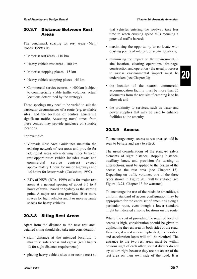
The usual considerations of the standard safetyelements of sight distance, stopping distance,auxiliary lanes, and provision for turning atintersections, must be applied to the design of theaccess to the rest area (see Chapter 13).Depending on traffic volumes, one of the threetypes shown in Figure 20.1 will be suitable (seeFigure 13.21, Chapter 13 for warrants).
To encourage the use of the roadside amenities, auniform standard of access configuration may beappropriate for the entire set of amenities along aparticular route, even though a lower standardmight be indicated at some locations on the route.
Where the cost of providing the required level ofaccess is high, consideration should be given toduplicating the rest area on both sides of the road.However, if a rest area is duplicated, decelerationand acceleration lanes will still be required. Theentrance to the two rest areas must be withinobvious sight of each other, so that drivers do nottry to turn right because they are not aware of therest area on their own side of the road. It is
March 2002 20-7
Road Planning and Design Manual Chapter 20: Roadside Amenities
20
preferable that the left side rest area appears firstto the approaching driver.
Details of the design of the access must be inaccordance with the requirements set out inChapter 13.
20.3.10 Rest Area Signing
Advance signing should provide the driver withadequate time to decide to use a particularamenity, given the amenity's location and the levelof facility provided.
The MUTCD (Main Roads, 1999d) givesappropriate advance signs 300 or 200m before arest area (depending on the speed environment)and at the turn-off to the facility in accordancewith current Australian standards.
In addition, advance warning signs are requiredat:
� 10km - indicate type of rest area and facilitiesprovided;
� 2km - indicate type of rest area and the distanceto the next rest area.
A �Fasten Seat Belts� sign should be placedadjacent to the exit points of all rest areas.
Note that on the advance warning signs, no morethan three symbols should be used to cover thefacilities required. It is intended that a standardsign G7-1-1 (MUTCD) should indicate a rest areaproviding the minimum facilities described inSection 20.3.2. Other symbols may be used whereservices in addition to these minima are provided.
Signs for heavy vehicle rest areas should not showthe facilities available to minimise use bymotorists and tourist traffic. These additionalusers may restrict the space available for trucksand create unnecessary disturbance to restingtruck drivers.
20-8 March 2002
Chapter 20: Roadside Amenities Road Planning and Design Manual
20
TYPE BA*
TYPE AU*
TYPE CH*
* See Chapter 13, Figure 13.21 Warrants for Rural Turn Lanes
Figure 20.1 Access to Rest AreasSource: Main Roads (1999a)
20.4 Stopping Places
20.4.1 Introduction
Stopping places are areas made available to enabledrivers to undertake short stops for a variety ofreasons, such as checking loads, attending to avehicle breakdown or enjoying a scenic view.
They serve the purpose of providing a relativelysafe location for immediate stopping needs at asafe distance from through traffic. Specificstopping places are required on sections of roadwhich do not provide adequate shoulder width toallow vehicles to stop clear of the carriagewaywith sufficient frequency to meet unexpectedstopping needs. There should be sufficientclearance from the through pavement to allowdrivers to inspect their vehicles safely.
Stopping places are designed to meet the specificneeds of both motorists and heavy vehicleoperators and can be co-located with a point ofinterest to tourists.
Stopping places for each direction should belocated in approximately the same place, butseparated to avoid having stopped vehicles onboth sides of the road at the same time. Trafficfrom each direction should arrive at its ownstopping place first. A spacing of 25 - 100mbetween adjacent tapers should be satisfactory.
Stopping places for commuter buses should bedesigned to the same standard as a heavy vehicleStopping Place when located in rural areas. Inurban areas, the stops should be designedaccording to the procedures described in Section20.7.
20.4.2 Motorist Stopping Places
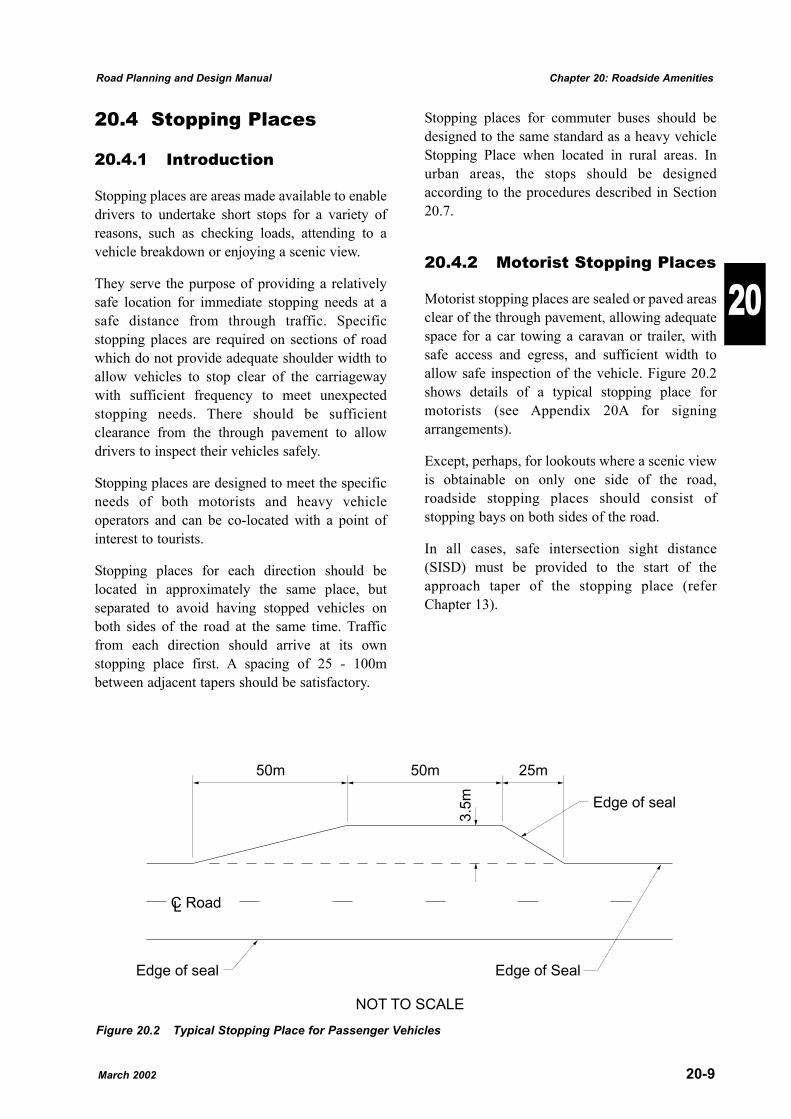
Motorist stopping places are sealed or paved areasclear of the through pavement, allowing adequatespace for a car towing a caravan or trailer, withsafe access and egress, and sufficient width toallow safe inspection of the vehicle. Figure 20.2shows details of a typical stopping place formotorists (see Appendix 20A for signingarrangements).
Except, perhaps, for lookouts where a scenic viewis obtainable on only one side of the road,roadside stopping places should consist ofstopping bays on both sides of the road.
In all cases, safe intersection sight distance(SISD) must be provided to the start of theapproach taper of the stopping place (referChapter 13).
March 2002 20-9
Road Planning and Design Manual Chapter 20: Roadside Amenities
20
3.5
m
25m50m50m
Edge of seal
Edge of seal Edge of Seal
NOT TO SCALE
C RoadL
Figure 20.2 Typical Stopping Place for Passenger Vehicles
20.4.3 Heavy Vehicle StoppingPlaces
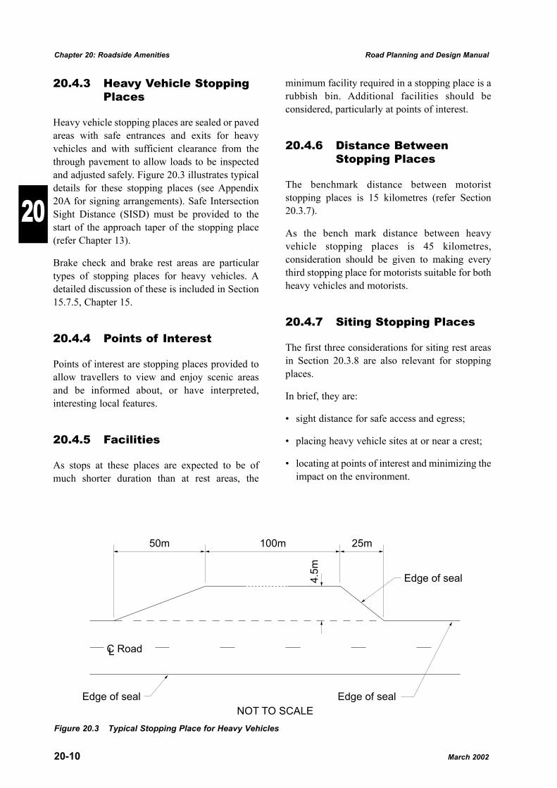
Heavy vehicle stopping places are sealed or pavedareas with safe entrances and exits for heavyvehicles and with sufficient clearance from thethrough pavement to allow loads to be inspectedand adjusted safely. Figure 20.3 illustrates typicaldetails for these stopping places (see Appendix20A for signing arrangements). Safe IntersectionSight Distance (SISD) must be provided to thestart of the approach taper of the stopping place(refer Chapter 13).
Brake check and brake rest areas are particulartypes of stopping places for heavy vehicles. Adetailed discussion of these is included in Section15.7.5, Chapter 15.
20.4.4 Points of Interest
Points of interest are stopping places provided toallow travellers to view and enjoy scenic areasand be informed about, or have interpreted,interesting local features.
20.4.5 Facilities
As stops at these places are expected to be ofmuch shorter duration than at rest areas, the
minimum facility required in a stopping place is arubbish bin. Additional facilities should beconsidered, particularly at points of interest.
20.4.6 Distance BetweenStopping Places
The benchmark distance between motoriststopping places is 15 kilometres (refer Section20.3.7).
As the bench mark distance between heavyvehicle stopping places is 45 kilometres,consideration should be given to making everythird stopping place for motorists suitable for bothheavy vehicles and motorists.
20.4.7 Siting Stopping Places
The first three considerations for siting rest areasin Section 20.3.8 are also relevant for stoppingplaces.
In brief, they are:
� sight distance for safe access and egress;
� placing heavy vehicle sites at or near a crest;
� locating at points of interest and minimizing theimpact on the environment.
20-10 March 2002
Chapter 20: Roadside Amenities Road Planning and Design Manual
20
4.5
m
25m100m50m
Edge of seal
Edge of seal
NOT TO SCALE
C RoadL
Edge of seal
Figure 20.3 Typical Stopping Place for Heavy Vehicles
When assessing a length of road for appropriatelocation of stopping bays, suitable sites for heavyvehicles (especially on crests) should bedetermined first. The other locations can then bedetermined to provide the required spacing.
Further, stopping places must be located so thatnearby residences are not inconvenienced.Preferably, they should not be visible fromresidences.
20.4.8 Geometry
For economy and practical reasons, stoppingplaces are located just off the roadway, but withsufficient offset to allow tapers for safe entry andexit and inspection of the vehicles.
Figure 20.2 shows a typical sealed motoriststopping place. The parking area is a minimum of3.5m wide and 50m long, to accommodatevehicles with suitable tapers from the edge of thesealed road shoulder for entry and exit.
Figure 20.3 shows a typical sealed heavy vehiclestopping place. The parking area is a minimum of4.5m wide and 100m long with suitable tapers forentry and exit from the edge of the sealed roadshoulder.
For both types of access, sight distance for safetyis essential and additional rainfall runoff from thesealed areas needs to be considered in the design.
20.4.9 Signs for StoppingPlaces
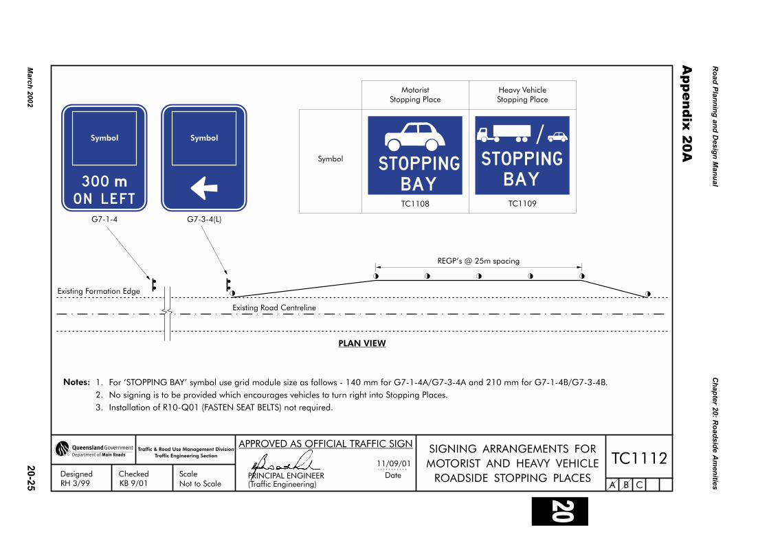
Advance and other road signs should be inaccordance with the MUTCD (Main Roads,1999d) and Drawing TC1112 (see Appendix20A).
20.5 Interception Sites
20.5.1 Introduction
Interception sites are safe areas outside the roadcarriageway provided for:
� weighing and inspecting heavy and commercialvehicles;
� inspecting other vehicles; and
� other enforcement (e.g. random breath testing)by appropriate officials.
Motorists may use them for short stops to inspecttheir own vehicles provided the site is not beingused for official purposes. Emergency vehiclesmay also use them.
They may function in conjunction with WIM(Weigh-In-Motion) sites on the roadway tooptimise the selection of vehicles to be weighed.These sites have piezo-electric detectors(weighing devices) to allow over-weight vehiclesto be detected and be directed to an interceptionsite for more accurate weighing
The concrete slab used for more accurateweighing devices at the interception site maysometimes also have one of these detectors, whichallows inspectors to limit the weighing to thosevehicles that are overloaded.
20.5.2 Site Selection forInterception Sites
The location of interception sites is influenced bythe design requirements of the access andweighing areas and the needs of the transportinspection officers. The routes taken by heavyvehicles (including alternative by-pass routes) arealso considered.
Sites have been selected at intersections of majorcorridors and on sections of a very long linkwhere there is reasonable access toaccommodation and facilities for enforcementofficers. In addition, consideration has been givento adopting enforcement sites that providemaximum flexibility and minimum inconvenienceto both inspectors and heavy vehicle operators(e.g. avoiding road trains crossing centre lines ordoing U-turns.).
Given the required sight distance and other safetyneeds, space is required for:
March 2002 20-11
Road Planning and Design Manual Chapter 20: Roadside Amenities
20
� deceleration and acceleration tapers and accessroads;
� storage for a number of vehicles on theapproach side of the weigh site for vehicleswaiting to be weighed;
� the actual process of weighing (see grade andcrossfall requirements below);
� a holding bay on the departure side of theweighing device for vehicles detectedoverloaded (Ideally, this area should allow forany necessary offloading to be undertaken, inaddition to the area needed for safe access toboth sides of the vehicle by inspectors tocomplete their records.); and
� sufficient width to permit safe passing ofstationary vehicles and Inspecting Officerswhere a vehicle is allowed to proceed.
General requirements are:
(a) Maximum longitudinal grade over theweighing area is 2.0% and maximumcrossfall is 3.0%. Desirable limits are levelgrade and 2.0% crossfall.
In addition the grade should be uniform overthe site. Changes in grade can be toleratedprovided areas of uniform grade sufficientto accommodate the longest vehicle,including B Doubles (Road Trains in someareas), can be clearly identified.
(b) Visibility to the start of the exit taper and theend of the entrance taper should be not lessthan the heavy vehicle stopping distance, andshould be carefully considered in the contextof the ruling traffic volume and speed.
(c) Where weighing sites are required for bothsides of the road to cover each traveldirection, they need not be located directlyopposite each other, although this isdesirable due to the logistics of providingpersonnel for both directions.
20.5.3 Geometry
Given the need for a heavily loaded vehicle todecelerate and enter an interception site wherethere may already be other heavy vehicles, thedesign of access to and from the area is critical forsafety reasons.
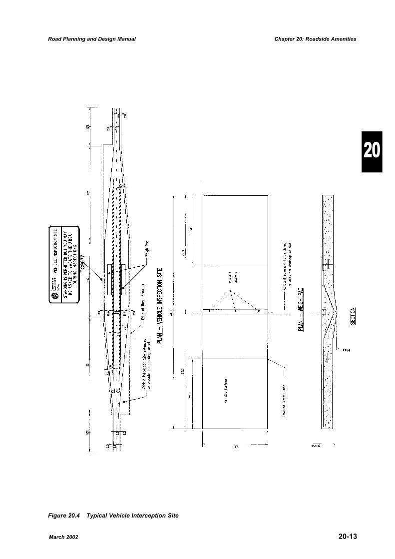
Figure 20.4 shows a typical major interceptionsite suitable for 1000 commercial vehicles per daywith semitrailers being 20% of the commercialvehicles. This design is suitable for sitesproviding for the brake/suspension tester.
The entry taper is longer than those for rest areasand stopping places as in those cases, the driversare expecting to stop and would be slowing downearlier. At interception sites, approach speedswould be higher depending on when the driversare asked to pull over by inspectors.
The overall dimensions of the site depend on theexpected number of commercial vehicles and theextent of the holding areas required.
Concrete pads with nominal dimensions of 40mlong x 5.0m wide are required for effectiveweighing of multi-combination vehicles.
20.5.4 EnvironmentalConsiderations
It may be necessary to collect run-off from the siteand process it in the appropriate way to avoidcontamination of waterways (see Chapter 3 andRoad Drainage Design Manual). Further, it maybe necessary to provide for the containment ofspillage that may occur on the site. Traps andretention basins should be designed into thescheme if appropriate.
20.5.5 Lighting
Where interception sites are to be used at night,they should be lit to provide safe workingconditions for inspectors and to ensure the safetyof motorists. The lighting is to be designed to thestandard defined in Chapter 17 of this Manual.
20-12 March 2002
Chapter 20: Roadside Amenities Road Planning and Design Manual
20
March 2002 20-13
Road Planning and Design Manual Chapter 20: Roadside Amenities
20
Figure 20.4 Typical Vehicle Interception Site
20.6 Rural School Bus Stops
20.6.1 Introduction
A rural bus stop is any school bus passengerpickup or set down area in a rural environment.
A school bus is any omnibus whilst it is beingused exclusively for the carriage of schoolchildren to or from a school.
To ensure the safety of school transport, thefollowing issues must be considered:
(a) selection and standard of school bus routes;
(b) provision of appropriate safe school busstops;
(c) signing of school bus routes and stops; and
(d) in-vehicle safety e.g. standees, seat belts andpadding.
This section of the Manual considers the siting,facilities and access requirements for (b) withsome reference to (c). QT and Main Roads 2000ais the chief source of information for this Sectionof the Manual.
20.6.2 Facilities
Depending mainly on the number of schoolchildren using a bus stop, consideration should begiven to providing the following facilities. (Forsafety, all facilities for children should be on theside of the bus stop furthest from the road.)
Waiting Areas
Where needed, waiting areas should be providedat school bus stops for school children toassemble and disperse.
These areas should be level, well drained and freefrom tripping hazards and may be gravelled andsealed. It is desirable to provide shade.
Bus Shelters
Passenger shelters should be provided wherejustified. The need should be determined from
factors such as:
� passenger demand;
� stop permanency;
� passenger waiting duration; and
� passenger convenience (e.g. protection fromheat, rain etc.).
The shelter should be located such that the busdriver is able to see the waiting children in time tostop the school bus. Speed environment andphysical features should be considered in thelocation of the shelter in relation to the trafficlanes. Desirably, the shelter should be locatedbeyond the clear zone so as not to become ahazard to road users. (Refer to Chapter 7 - CrossSection for further discussion on clear zones.)
Parking Facilities
Providing safe parking facilities should beconsidered at school bus stops where parents withvehicles assemble to drop-off/collect children.
Adequate area should be available to permitparents to park their vehicle, drop-off the childrenand collect them safely with minimum disruptionto the children and traffic. If a separate area is tobe provided, Section 20.4, Stopping Places maybe used as a guide.
Pedestrian Crossings and Refuges
Where necessary, safe pedestrian crossings shouldbe provided at the school bus stop in accordancewith the warrants set out in the MUTCD (MainRoads, 1999d).
Travel Paths for Pedestrians
Safe travel paths should be available for childrento walk to and from the school bus stop (e.g. froma separate parking area).
The need for children to walk along the edge of avehicle carriageway should be avoided wherepossible, especially on roads where the trafficspeed, volume and proportion of heavy vehiclesare high. Preferably, paths at the maximumdistance from the traffic lanes should be providedfor children to use. In some cases, facilities for
20-14 March 2002
Chapter 20: Roadside Amenities Road Planning and Design Manual
20
bicycles on off-road paths and storage for bicyclesshould be considered.
20.6.3 Siting School Bus Stops
School bus stops should be located and designedto:
(a) maximize the safety of school children andother road users; and
(b) minimise interference to traffic flow on theroad system.
Good practice in relation to school bus stoplocation, design and safety includes consideringthe following:
� crash history in the vicinity of the school busstop;
� visibility to/from the school bus stop facilities;
� providing for passing a stationary bus at theschool bus stop;
� roadway characteristics in the vicinity of theschool bus stop;
� traffic characteristics in the vicinity of theschool bus stop;
� providing bus stop facilities at intersections ormid-block;
� signing specifically for school bus stops andcrossing areas;
� providing passenger waiting facilities; and
� providing pedestrian facilities.
Requirements for school bus stops should beresolved with the appropriate QueenslandTransport officers.
Crash History
School bus stops should be avoided in areas witha history of particular types of crashes (e.g. run-off the road crashes) which may place the bus stopusers (e.g. children waiting at stop, bus stopping)at risk.
Visibility Issues
The optimum locations for school bus stops are onsections of road with a straight alignment with auniform gradient. School bus stops should not belocated in unexpected situations and/or atlocations with limited visibility, such as justaround sharp horizontal curves, or just over crests.
The visibility of the school bus stop should besufficient to allow:
� following vehicles to stop or slow down safelybehind the school bus while the bus is enteringor leaving the bus stop; and/or
� vehicles to safely pass the school bus while it isengaged in pick up/set down activities.
It is desirable that at least safe intersection sightdistance be provided to the bus stop (see Chapter13). Where this cannot be achieved, a full pull offarea is required with at least stopping sightdistance to the start of the pull off area. If childrenhave to cross the road to reach the stop, thevisibility to the crossing point must satisfy both ofthe criteria:
� Approach Sight Distance
� Crossing Sight Distance
in accordance with the procedures set out inAustroads (1999) Guide to Traffic EngineeringPractice - Part 13 Pedestrians (see also Chapters 5and 13).
Where these conditions cannot be met, the busstop should be relocated to a site that does.
Stopping distances for passenger vehicles, busesand trucks are given in Austroads (1988) Guide toTraffic Engineering Practice, Part 5 - Intersectionsat Grade. See also Chapter 8 - Sight Distance forfurther discussion.
Passing Zones
Safe and effective passing zones at bus stops ontwo lane roads require both adequate sight distanceto opposing vehicles and adequate passing zonelength. If these cannot be provided, a pull off areawill be required in accordance with Figure 20.5.
March 2002 20-15
Road Planning and Design Manual Chapter 20: Roadside Amenities
20
To allow for safe passing of vehicles at bus stops,it may be necessary to provide pull-off areas forbuses to stop. It should be noted that inaccordance with the Traffic Act, where there is nocontinuous dividing line or dividing strip, theremust be at least 3 metres of the road alongside thevehicle that is clear for other vehicles to pass.Where there is a continuous dividing line ordividing strip, the driver must position the vehicleat least 3 metres from any dividing line ordividing strip. However, for added safety, a cleardistance of 4.0m between the dividing line and theoffside of the parked bus is required.
Roadway Grades
The school bus stop should be appropriatelylocated in relation to the roadway grade and anyauxiliary lanes.
Where visibility is not an issue and where gradesare very steep, school bus stops should be avoidedin sag curves or on the grade incline due to thedifficulty and hazard of decelerating and/oraccelerating amid general traffic.
School bus stops must not be located within thetapering sections of auxiliary lanes (e.g.overtaking lanes, climbing lanes, descendinglanes, turning lanes, passing bays). Stops must notbe located on grades where runaway vehiclefacilities are required.
Lanes and Shoulders
Adequate shoulders should be provided toimprove safety at school bus stops. (See also�Passing Zones� above.)
Widening road shoulders to allow the bus to standclear of the traffic lanes provides improved trafficflow and safety. In addition, improved warning ofthe approaching stop with appropriate signs isdesirable.
At areas where the school bus must remainstationary for some period of time (e.g. routeterminal etc.), the stopped bus must be locatedclear of through traffic lanes. It should be notedthat in accordance with the Traffic Act, vehicles7.5 metres long or longer, may only park on theroad shoulder in a non-built up area.
Road Surface Condition
The road surface at the school bus stop should besuitable under wet weather conditions for busperformance.
If necessary, placing selected gravel or sealing thebus stop area and its access should be carried outto make the area safe for the bus and waitingschool children.
Bus Terminals
Suitable allowance for a bus to turn around safelymust be provided at the terminus of a school busroute. This may take the form of shoulderwidening, off road faclity or cul-de-sac dependingon the circumstances of the site.
Side Roads and Property Accesses
As stopped/stopping buses cause conflict intraffic, locating bus stops at intersectionsminimizes the conflict area. Property accesses to alesser degree are also places where slowervehicles would expect to be encountered bythrough traffic.
Intersections and property accesses may also belogical places for picking up school children thatlive on the side road or on the property itself. Assome of the paved or sealed area required for abus stop may already be in place for theintersection or property access, there may be asaving in cost in providing a bus stop at one ofthese locations.
20.6.4 Access
At Intersections
A school bus stop should be located on thedeparture side of intersections, children's crossinglocations, and property accesses, where possible.
A bus stop located on the departure side of anintersection is generally safer than one located onthe approach side as children cross behind the buswhere they can be seen. In this position, the busdoes not block the view of traffic controls andother intersection traffic.
20-16 March 2002
Chapter 20: Roadside Amenities Road Planning and Design Manual
20
March 2002 20-17
Road Planning and Design Manual Chapter 20: Roadside Amenities
20
25m 15m 15m
Traffic FlowEdge Line
Centre Line
SideRoad
Bus Stopping Area
Gravel SubbaseAt existing crossfallBitumen seal (desirable)
5.0mmin
15m 25m
Traffic Flow
Edge Line
Centre Line
SideRoad
Bus Stopping Area
Gravel SubbaseAt existing crossfallBitumen seal (desirable)
5.0mmin
(a) School bus stopping area on same side as side road
(b) us stopping area on opposite side to side roadSchool b
15m
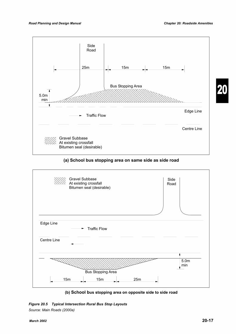
Figure 20.5 Typical Intersection Rural Bus Stop LayoutsSource: Main Roads (2000a)
Other advantages of the departure side bus stopinclude:
� reduced bus conflict with left turning vehicles;
� increased intersection capacity by freeing thekerb lane for through movement;
� improved sight distances at intersections;
� shorter kerb length requirements for bus stopapproaches; and
� easier bus re-entry into traffic after passengerloading/unloading.
School bus stops should not be located oppositethe terminating leg of a T-junction for safety andefficiency reasons. Typical intersection bus stoplayouts are detailed in Figure 20.5.
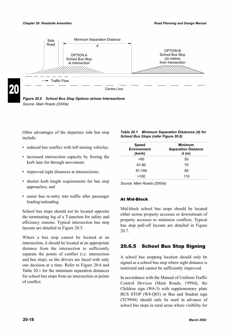
Where a bus stop cannot be located at anintersection, it should be located at an appropriatedistance from the intersection to sufficientlyseparate the points of conflict (i.e. intersectionand bus stop), so the drivers are faced with onlyone decision at a time. Refer to Figure 20.6 andTable 20.1 for the minimum separation distancesfor school bus stops from an intersection or pointsof conflict.
Table 20.1 Minimum Separation Distances (d) forSchool Bus Stops (refer Figure 20.6)
Speed MinimumEnvironment Separation Distance
(km/h) d (m)<60 50
61-80 7081-100 85>100 110
Source: Main Roads (2000a)
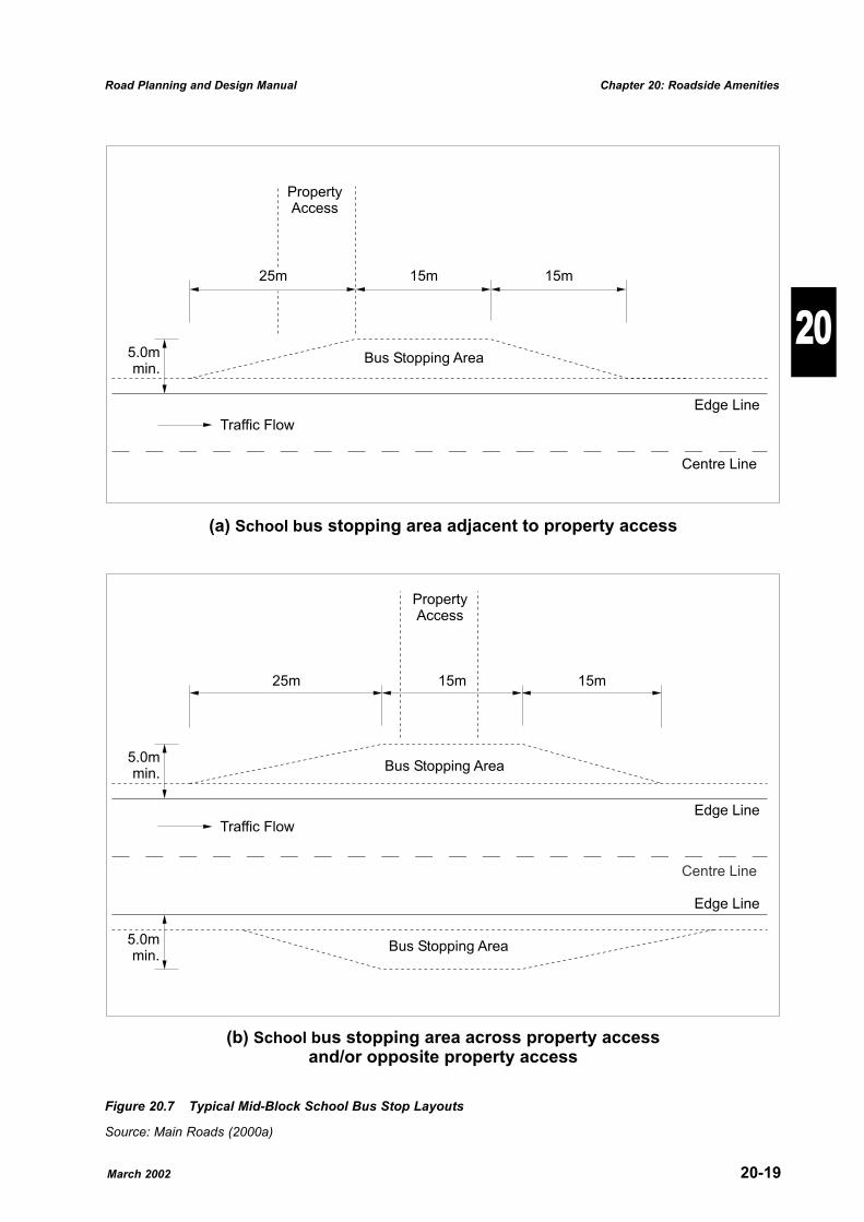
At Mid-Block
Mid-block school bus stops should be locatedeither across property accesses or downstream ofproperty accesses to minimize conflicts. Typicalbus stop pull-off layouts are detailed in Figure20.7.
20.6.5 School Bus Stop Signing
A school bus stopping location should only besigned as a school bus stop where sight distance isrestricted and cannot be sufficiently improved.
In accordance with the Manual of Uniform TrafficControl Devices (Main Roads, 1999d), theChildren sign (W6-3) with supplementary plateBUS STOP (W8-Q03) or Bus and Student sign(TC9944) should only be used in advance ofschool bus stops in rural areas where visibility for
20-18 March 2002
Chapter 20: Roadside Amenities Road Planning and Design Manual
20Traffic Flow
Centre Line
SideRoad
OPTION ASchool Bus Stop
at intersection
OPTION BSchool Bus Stop
from intersection(d) metres
Minimum Separation Distance
d
Figure 20.6 School Bus Stop Options at/near IntersectionsSource: Main Roads (2000a)
March 2002 20-19
Road Planning and Design Manual Chapter 20: Roadside Amenities
20
25m 15m 15m
25m 15m 15m
(a) us stopping area adjacent to property accessSchool b
Bus Stopping Area
Bus Stopping Area
Centre Line
Edge Line
Edge Line
5.0mmin.
PropertyAccess
Bus Stopping Area
Traffic Flow
Edge Line
Centre Line
(b) us stopping area across property accessand/or opposite property access
School b
PropertyAccess
Traffic Flow
5.0mmin.
5.0mmin.
Figure 20.7 Typical Mid-Block School Bus Stop Layouts
Source: Main Roads (2000a)
approaching drivers to any children waiting at thebus stop is less than 200 metres.
It is not intended that these signs should begenerally used at school bus stops. To improvesafety, consideration should be given to relocatingthe bus stop to a location with adequate visibility.
Children�s crossing areas should only be signedwhere for safety reasons it is necessary to warnmotorists of the possible presence of schoolchildren on the road.
The Children sign (W6-3) alone should only beused where:
(a) pedestrian volumes are significant butinsufficient to justify a pedestrian crossing(zebra) or traffic signals;
(b) the presence of pedestrians may not beexpected; or
(c) the pedestrian demand extends over a lengthof road.
To maintain the credibility of these signs it isimportant that they be removed as soon as thesituation ceases to warrant such signing.
20.7 Urban Bus Stops
20.7.1 Introduction
Although considerations for urban bus stops havemuch in common with those for rural school busstops, there are also major differences. Some ofthese differences are:
� a lower speed environment (50-60 km/h speedlimits in urban areas and 100 km/h common onrural bus routes);
� much more frequent stop visits by buses inurban areas, compared with only 2 per day atrural bus stops (1 trip to and from school);
� intersections and property accesses are muchmore common in urban areas and these must bekept completely clear, unlike those at rural busstops; and
� choice of bus stop location is more limited inurban areas, with routes defined and shorterdistance between stops.
However, the key considerations of minimisingthe interference to traffic flow on the road systemand safety for the buses and their passengersremain the same.
20.7.2 Facilities
For the facilities mentioned below, the basicconsiderations are similar to those for rural busstops and reference should be made to Section20.6.2 for further details.
Bus Shelters and Waiting Areas
Because of the greater demand, bus shelters atregular intervals are expected in urban areas.
Parking Facilities
Apart from Park and Ride areas which may bequite large (e.g. providing parking bays for 50-250 cars), parking facilities are not required forthe sole reason of servicing passengers for buses.
Pedestrian Crossings and Refuges andTravel Paths (Footpaths)
These will be more common in urban areas, butexist for reasons other than use by bus passengers.
Lighting
Bus stops in urban areas should be lit to:
� provide a deterrent to crime against peoplewaiting for a bus;
� improve the visibility of the stop, therebyincreasing the safety of people waiting.
20.7.3 Siting Urban Bus Stops
Considerations for the placement of urban busstops include:
� minimising interference to traffic flow(indented bus bays if necessary);
20-20 March 2002
Chapter 20: Roadside Amenities Road Planning and Design Manual
20
� spacing of stops as a trade off between impacton traffic and passenger demand (e.g. QT andMain Roads (2000a) gives distances betweenstops as 150 - 365 m in urban areas and 180 -760 m in suburban areas in the USA).
� volume and turning movements of traffic;
� safety of buses (visibility, passing zones,roadway grades etc, as in Section 20.6.3);
� safety of people waiting for and exiting buses(including the proximity of pedestriancrossings and intersections);
� access for people with impairments;
� the proximity of footpaths and kerb ramps;
� the possibility of having a stop for travel in theopposite direction in near proximity;
� street lighting;
� adequate space for the number of busesexpected at the one time;
� impact of the bus stop on nearby properties;
� on-street parking of passenger and commercialvehicles;
� traffic control signs and signals (lights, stop,yield signs);
� width of footpaths; and
� property accesses.
20.7.4 Access
Access requirements are discussed in the�kerbside bus stops� and �indented bus bays�sections below.
Considerations are similar to those for rural busstops with the added complication of the presenceof close intersections, bus queues and theincreased probability of buses arriving at oppositesides of the road at the same time.
There should be sufficient length of road for busesto leave stops, move to the centre lane and turnright at the next intersection where applicable.
Mid-block stops remove the run-in and run-outmanoeuvres from the vicinity of intersections andmay cause less interference with traffic.
Departure side stops are preferred at schoolcrossings, pedestrian activated signals andmarked pedestrian crossings as buses are lesslikely to obscure pedestrians at such crossings.
Where buses are required on both sides of busyroads, they should be staggered or fully indentedinto the verge or reservation to avoid the creationof a bottleneck when buses from oppositedirections arrive concurrently.
Kerbside Bus Stops
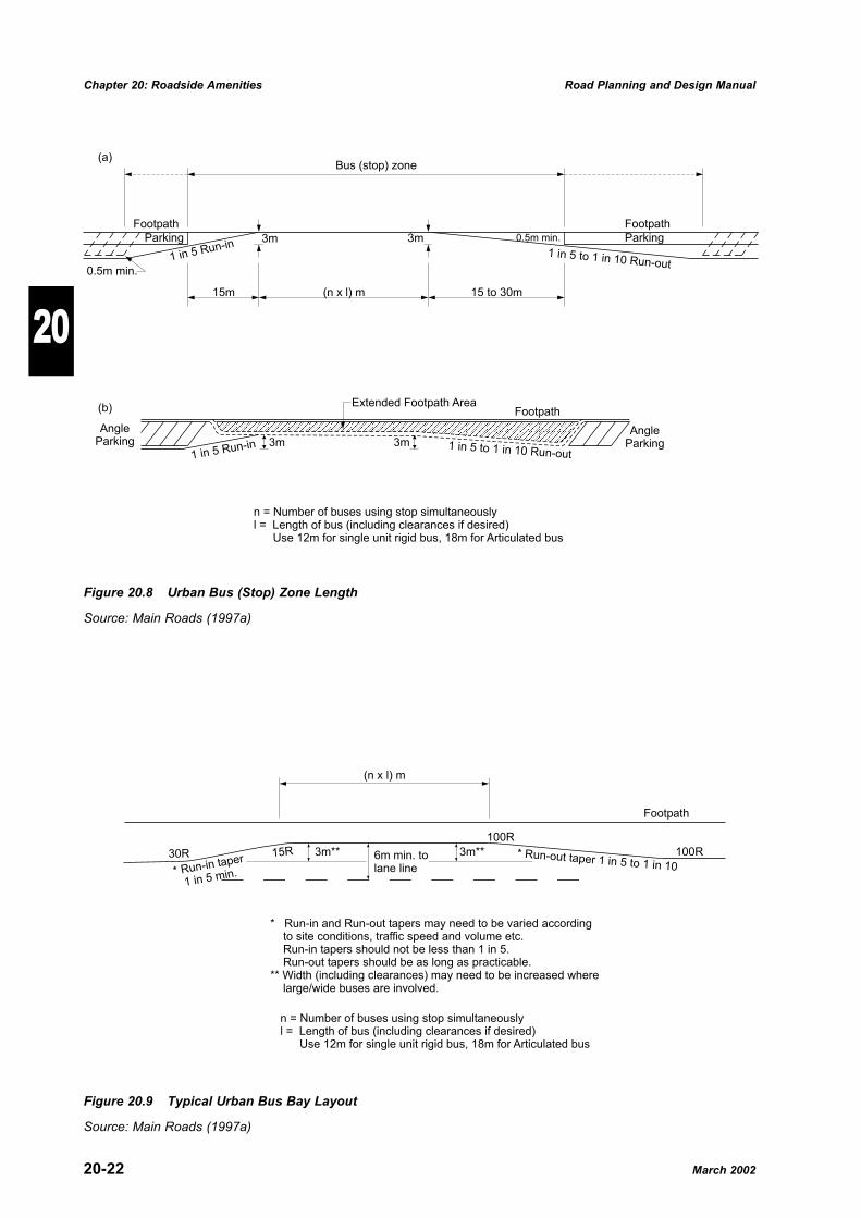
The length of kerb line needed to be free ofparking to provide for a bus (stop) zone may bedetermined as shown in Figure 20.8.
Where angle parking is involved, the run-in andrun-out areas generally need to be lengthened atthe taper rates given in Figure 20.8(a). Where theangle parking is a relatively permanentarrangement, extending the footpath area asillustrated in Figure 20.8(b) shortens the requiredbus (stop) zone, minimizes the required deviationof the bus and allows more footpath area forpassengers to wait or for a bus shelter to beerected.
Run-in and run-out tapers should always beprovided to ease entry to and exit from thethrough traffic lanes. Entry may be furtherassisted by regulations giving priority to the busfor this manoeuvre in Queensland.
Bus route terminal stands or areas where busesmust remain for some time should be located clearof through traffic lanes or at sites where thedisruption to traffic flow and parking isminimised.
Indented Bus Bays
Bus bays may be partially or fully indented intothe adjacent footpath or reservation so that the busis clear of traffic while it is setting down or takingup passengers.
A typical bus bay layout is shown in Figure 20.9.With kerbside parking there is generally little
March 2002 20-21
Road Planning and Design Manual Chapter 20: Roadside Amenities
20
20-22 March 2002
Chapter 20: Roadside Amenities Road Planning and Design Manual
20
Footpath
ParkingParking 0.5m min.
0.5m min.
(a)
(b)
1 in 5 to 1 in 10 Run-out1 in 5 Run-in
Footpath
Bus (stop) zone
3m
15m (n x l) m
3m
15 to 30m
AngleParking
AngleParking
n = Number of buses using stop simultaneouslyl = Length of bus (including clearances if desired)
Use 12m for single unit rigid bus, 18m for Articulated bus
1 in 5 Run-in
Footpath
1 in 5 to 1 in 10 Run-out
Extended Footpath Area
3m 3m
Figure 20.8 Urban Bus (Stop) Zone Length
Source: Main Roads (1997a)
* Run-out taper 1 in 5 to 1 in 10* Run-in taper
1 in 5 min.
Footpath
(n x l) m
n = Number of buses using stop simultaneouslyl = Length of bus (including clearances if desired)
Use 12m for single unit rigid bus, 18m for Articulated bus
15R
100R
100R30R 3m** 3m**6m min. tolane line
* Run-in and Run-out tapers may need to be varied accordingto site conditions, traffic speed and volume etc.Run-in tapers should not be less than 1 in 5.Run-out tapers should be as long as practicable.
** Width (including clearances) may need to be increased wherelarge/wide buses are involved.
Figure 20.9 Typical Urban Bus Bay Layout
Source: Main Roads (1997a)
advantage in providing an indented bus bayexcept where �clearway� conditions may beimplemented in peak periods. Where this is thecase, off-peak parking needs to be prohibited overthe length of the bus bay plus run-in and run-outtapers (across the parking width) as shown inFigure 20.8(a).
20.7.5 Urban Bus Stop Signing
All traffic signs are to be in accordance with theMUTCD (Main Roads, 1999d).
20.8 Roadside Vending Sites
Roadside vending involves the selling of articleseither directly or from a stall or standing vehicleon a road. The selling of goods and services in thisway is potentially dangerous, as vehicles maysuddenly swerve or stop, creating unsafesituations with moving traffic.
Stalls on private land adjacent to the road willpotentially attract the same approval conditions asroadside vending sites within the road reserve,because of the possible impact on traffic safety.
Main Roads, 2000b gives the Policy for MainRoads on roadside vending.
Design details should be similar to those for TruckStopping Places.
References
Austroads (1988): Guide to Traffic EngineeringPractice, Part 5 - Intersections at Grade.
Austroads (1995): Guide to Traffic EngineeringPractice, Part 13 - Pedestrians.
Cockshutt, T. (1997): Rest Areas of the NationalHighway System, A Discussion Paper,Commonwealth Department of Transport andRegional Development.
Department of Main Roads, Queensland (1985):Policy for the Provision of Roadside StoppingPlaces.
Department of Main Roads, Queensland (1994):Roadside Landscaping, Roads Policy Manual.
Department of Main Roads, Queensland (1997a):Service Centre Strategy - No. 2/97 GatewayMotorway (South-East Freeway - BruceHighway), Guidelines and Strategies, Road PolicyManual.
Department of Main Roads, Queensland (1997b):Service Centre Strategy - No. 1/97 BruceHighway (Pine River - Gympie), Guidelines andStrategies, Roads Policy Manual.
Department of Main Roads, Queensland (1998a):Service Centre Policy, Roads Policy Manual.
Department of Main Roads, Queensland (1998b):Access Policy for Roadside Service CentreFacilities on Access-Limited Roads, Roads PolicyManual.
Department of Main Roads Queensland (1999a):Roadside Amenities Strategy for Main Roads,Draft.
Department of Main Roads, Queensland (1999b):Provision of Roadside Amenities, Roads PolicyManual.
Department of Main Roads, Queensland (1999c):Roadside Fire Threat Management - Firebreaks -Guidelines for Fire Threat Management Policy.
Department of Main Roads, Queensland (1999d):Manual of Uniform Traffic Control Devices.
Queensland Transport and Department of MainRoads, Queensland (2000a): Guide for the RoadSafety Management of Rural Bus Routes and BusStops, Draft.
Department of Main Roads, Queensland (2000b):Roadside Vending - Draft Policies and Guidelines.
Highway Research Board, Washington D.C.(1952): Special Report 7, Parking Turnouts andRest Areas.
Highway Research Board, Washington D.C.(1973): Rest Areas, N.C.H.R.P. Synthesis ofHighway Practice 20.
March 2002 20-23
Road Planning and Design Manual Chapter 20: Roadside Amenities
20
Illuminating Engineering Society of NorthAmerica (1985): IES CP-38-1985, LightingRoadway Safety Rest Areas.
Road Traffic Authority and Department of LocalGovernment, New South Wales (1996): StreetVending.
Road and Traffic Authority, New South Wales(1999): Vehicle Stopping Areas.
Traffic Authority of New South Wales (1988):Interim Guidelines for the Planning and Design ofSchool Bus Routes and Bus Stops.
Transportation Research Board, Washington D.C.(1996): Transit Cooperative Research ProgramReport 19, Guidelines for the Location andDesign of Bus Stops.
Relationship to OtherChapters
� Relies on Chapters 13 and 15 for details ofaccess requirements;
� Chapter 16 deals with spacing of ramps and thisaffects location of Service Centres;
� Sight distance requirements are provided inChapter 9;
� Chapter 4 discusses urban bus stops in thecontext of arterial road design;
� Chapter 5 provides details of pedestriancharacteristics and design vehicles.
20-24 March 2002
Chapter 20: Roadside Amenities Road Planning and Design Manual
20
Appendix 20A
March 2002
20-25
Road Planning and D
esign Manual
Chapter 20: R
oadside Am
enities20
SIGNING ARRANGEMENTS FORMOTORIST AND HEAVY VEHICLE
ROADSIDE STOPPING PLACESKB 9/01RH 3/99
11/09/01 TC1112ScaleNot to Scale
CheckedDesignedA
APPROVED AS OFFICIAL TRAFFIC SIGN
Date
1. For ‘STOPPING BAY’ symbol use grid module size as follows - 140 mm for G7-1-4A/G7-3-4A and 210 mm for2. No signing is to be provided which encourages vehicles to turn right into Stopping Places.3. Installation of R10-Q01 (FASTEN SEAT BELTS) not required.
G7-1-4B/G7-3-4B.Notes:
PLAN VIEW
TC1109TC1108
G7-1-4
Existing Formation Edge
Existing Road Centreline
REGP’s @ 25m spacing
G7-3-4(L)
/
MotoristStopping Place
Heavy VehicleStopping Place
Symbol
B
Traffic & Road Use Management DivisionTraffic Engineering Section
PRINCIPAL ENGINEER(Traffic Engineering) C
300
Symbol Symbol
![Rest Areas and Roadside Facilities Maintenance [Location] [Date] Weeds and Roads D. PolsterJ. Leekie BC MoT](https://img.pdfslide.us/doc/110x75/5516c243550346f6208b58b7/rest-areas-and-roadside-facilities-maintenance-location-date-weeds-and-roads-d-polsterj-leekie-bc-mot.jpg)


![Roadside Vegetation Control [Location] [Date] Weeds and Roads D. PolsterJ. Leekie BC MoT](https://img.pdfslide.us/doc/110x75/551b3745550346dd1a8b517d/roadside-vegetation-control-location-date-weeds-and-roads-d-polsterj-leekie-bc-mot.jpg)