Embed Size (px)
Citation preview

Roadrunner, a High-Performance Responsive Space Mission2004 SmallSat ConferenceTerrance Yee, MSI

August 9, 2004 2
Roadrunner/TacSat-2 Mission Objectives
• Concept Baseline to Launch Ready in 14 months• Storage to On-Orbit Functionality in 7 Days• Autonomous On-Orbit Commissioning in 24
Hours• In-Field Tactical C3 of Satellite• Visible Imagery Under 1 Meter GSD• Geolocate RF Targets and Image in Same Pass• Demonstrate Additional Advanced Technologies
August 9, 2004 3
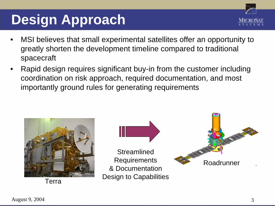
Design Approach• MSI believes that small experimental satellites offer an opportunity to
greatly shorten the development timeline compared to traditionalspacecraft
• Rapid design requires significant buy-in from the customer including coordination on risk approach, required documentation, and most importantly ground rules for generating requirements
Terra
StreamlinedRequirements
& DocumentationDesign to Capabilities
Roadrunner
August 9, 2004 4
Payload Descriptions
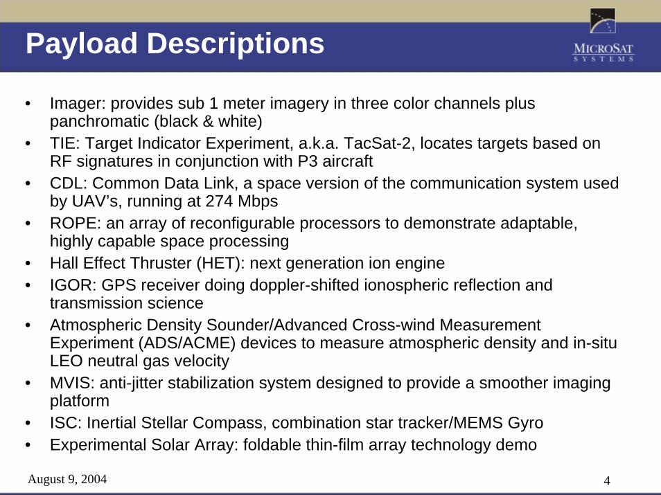
• Imager: provides sub 1 meter imagery in three color channels plus panchromatic (black & white)
• TIE: Target Indicator Experiment, a.k.a. TacSat-2, locates targets based on RF signatures in conjunction with P3 aircraft
• CDL: Common Data Link, a space version of the communication system used by UAV’s, running at 274 Mbps
• ROPE: an array of reconfigurable processors to demonstrate adaptable, highly capable space processing
• Hall Effect Thruster (HET): next generation ion engine• IGOR: GPS receiver doing doppler-shifted ionospheric reflection and
transmission science• Atmospheric Density Sounder/Advanced Cross-wind Measurement
Experiment (ADS/ACME) devices to measure atmospheric density and in-situ LEO neutral gas velocity
• MVIS: anti-jitter stabilization system designed to provide a smoother imaging platform
• ISC: Inertial Stellar Compass, combination star tracker/MEMS Gyro • Experimental Solar Array: foldable thin-film array technology demo

August 9, 2004 5
Roadrunner Launch ConfigurationImager Telescope
Stowed Solar ArraysISC CGA
Launch Vehicle Adapter
Composite Bus Structure
Bus Payload Deck

August 9, 2004 6
Roadrunner Side and Top Views
-X
+Z
-X
ISC CGA
ISC CGA
Top View
Side View
ADS
TIE
IGOR
Imager
CDL
HET
Terma HE-5ASACME
ADMS
Antennas

August 9, 2004 7
RR ISC Configuration: SV Deployed
ISC
HET
TermaStar Tracker
Solar Arrays (Back Side)

August 9, 2004 8
Roadrunner Deployed View 2
ExperimentalSolar Array
Main Solar Array(Single Junction GaAs)
PayloadElectronics
TIE
ADMS
ACME
IGOR

August 9, 2004 9
10:30 am Ascending Node Sun Synch Orbit, View from Sun
VelocityP/L Ops
Orientation
Solar InertialOrientation

August 9, 2004 10
Roadrunner Block Diagram
LNA
Patch Antenna
Temp Sensors
ADCS
Thermal
Launch Vehicle Sep
GFESolar Array
Battery
Magnetometer
Torque Rods
HVPS
Reaction Wheels
Sun Sensors
Mini-SGLS
Star Tracker
S/A Deploy
IGORGPS Ant
Commands/Data
Swtch’d, 28 Unreg Power
Existing TS21 Design
Mod to Existing Design
New Design
Off the Shelf/Build to Print
PropulsionHET/PPU
Mechanisms
TIE PIU
Telecom
ACME Sensor
Experimental Array
Imager Electronics
ROPE Electronics
MVIS
Imager Optics
ACME Electronics
ADMSADS
U/L Patch AntennaReflector Dish Antenna
MMA
CDL
Whip Antr
Whip Antr
Whip Antr
Whip Ant
HornHornHornHornHornHorn
UHF TransponderUHF Ant
Precision Clock
AIS/CuF-2SUnit
GPS
GPS Antenna
RF Front End
TIE PPU
TIE
IntegratedAvionics
Unit
(C&DH and EPS)
AutonomousSoftware
Inter/Intra Instr Hrnss
Spacecraft Bus
Payloads
IMU (LN-200S)
Filter
FilterMPM
Combiner
Heaters
MVIS Electronics
Exp Array Sep
Imager Lock Down
August 9, 2004 11
Roadrunner General Capabilities
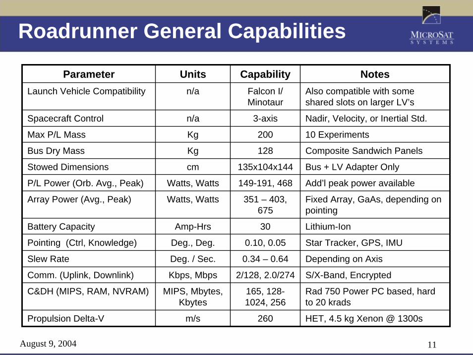
Parameter Units Capability NotesLaunch Vehicle Compatibility n/a Falcon I/
MinotaurAlso compatible with some shared slots on larger LV’s
Spacecraft Control n/a 3-axis Nadir, Velocity, or Inertial Std.
Slew Rate Deg. / Sec. 0.34 – 0.64 Depending on Axis
C&DH (MIPS, RAM, NVRAM) MIPS, Mbytes, Kbytes
165, 128-1024, 256
Rad 750 Power PC based, hard to 20 krads
Max P/L Mass Kg 200 10 Experiments
Bus Dry Mass Kg 128 Composite Sandwich Panels
Stowed Dimensions cm 135x104x144 Bus + LV Adapter Only
P/L Power (Orb. Avg., Peak) Watts, Watts 149-191, 468 Add’l peak power available
Array Power (Avg., Peak) Watts, Watts 351 – 403, 675
Fixed Array, GaAs, depending on pointing
Battery Capacity Amp-Hrs 30 Lithium-Ion
Pointing (Ctrl, Knowledge) Deg., Deg. 0.10, 0.05 Star Tracker, GPS, IMU
Comm. (Uplink, Downlink) Kbps, Mbps 2/128, 2.0/274 S/X-Band, Encrypted
Propulsion Delta-V m/s 260 HET, 4.5 kg Xenon @ 1300s

August 9, 2004 12
Roadrunner Master Equipment ListConfiguration 4/29/04
Qty Mass (kg) Total (CBE) Growth (%) AllocationADCS 9.09 9.3% 9.93
Ball Star Camera + Light Shade 1 2.74 2.74 15% 3.15IMU: LN-200S 1 0.75 0.75 15% 0.86Magnetometer (three-axis) 1 0.20 0.20 5% 0.20Torque Rod 3 0.33 0.99 5% 1.04Sun sensor, Coarse 3 0.02 0.06 5% 0.06Sun Sensor Bracket without standoff 1 0.20 0.20 25% 0.24Reaction Wheel 3 1.39 4.16 5% 4.37
Avionics 4.65 11.5% 5.18Integrated Avionics Unit (IAU) 4.65 12% 5.18
Power 38.93 10.0% 42.81Battery 1 9.25 9.25 10% 10.18Solar Array Wing 2 14.84 29.68 10% 32.63
9.00 25.0% 11.25Propulsion System 12.89 8.6% 13.99
Thruster and Cathode 1 1.12 1.12 15% 1.29PPU 1 3.66 3.66 15% 4.21Xenon Feed System (XFS) inc. Tank 1 3.10 3.10 10% 3.41Xenon 1 4.50 4.50 0% 4.50PPU-to-Thruster Harness 1 0.50 0.50 15% 0.58
Structures 47.89 15.0% 55.07Thermal Control 2.83 73.9% 4.92Telecom (Mini-SGLS) 2.29 11.2% 2.54Spacecraft Total 127.55 14.2% 145.69Payload 178.40 12.1% 199.91Prop Sensors 2.67 12.3% 3.00Experiments 181.07 12.1% 202.91Ballast 1.30 1.30Launch Vehicle I/F 4.09 8.1% 4.42Launch Vehicle I/F 4.09 8.1% 4.42
Satellite 309.92 349.90Launch Mass 314.01 40.30 354.32
Mass (kg)
Harness
Subsystem/Component

August 9, 2004 13
Power System Capabilities
• 149-191 Watts of Payload Power Available Depending upon Flight Attitude Excluding Experimental Arrays
• 468 Watts of Peak Payload Power Available– Higher Power Circuits Available as an Option
• Up to 675 W Peak Array Generation Allowable• 30 Amp-Hr Battery Capacity From 8-cell Li-Ion Battery• Bus Provides Solar Array Switching/Battery Charging
Autonomously• 16 total 2 Amp switched lines available to Payloads• 33 Six-Amp switched lines available to Payloads• Up to 8 Redundant Actuators Can Be Armed/Fired from
4 Separate Circuits

August 9, 2004 14
Power System Components
GaAs Solar Array standard, FITS Flexible Array or Triple Junction options available
YardneyLi-Ion Flight Battery30 A-Hr, 11,000 cycles @ 20% DoD28-34V nominal bus
Custom Harness, No Bake-out Required, Full EMI/EMC Available
Up to 8 redundant pyrosarmed/fired from 4 circuits20 Amp total load standard,
Broad Reach IAU w/ integrated EPS

August 9, 2004 15
Bus Structures
TS21 Qualified Structure-DeltaIV/ESPA Loads-Correlated FEM-181 Kg at 18.8 g’s -27.7 Hz
New Payloads-410 kg Max-< 25 Hz
RR Baseline Configuration-270 Kg Max, 8 g’s-25 Hz
RoadrunnerFirst Mode Frequency: 25.2 Hz-No Structure Re-Qual Required
Adding New Roadrunner Payloads Required:
-Stiffening Structural Load Path-Fixing adapter to S/C not LV-Design to 25 Hz Above Lightband
-Re-Qualify For Stiffness and Strength (August ‘04)-Proto-Flight Vibration Testing of Structure
Re-Qual Structure
August 9, 2004 16
ADCS Capabilities
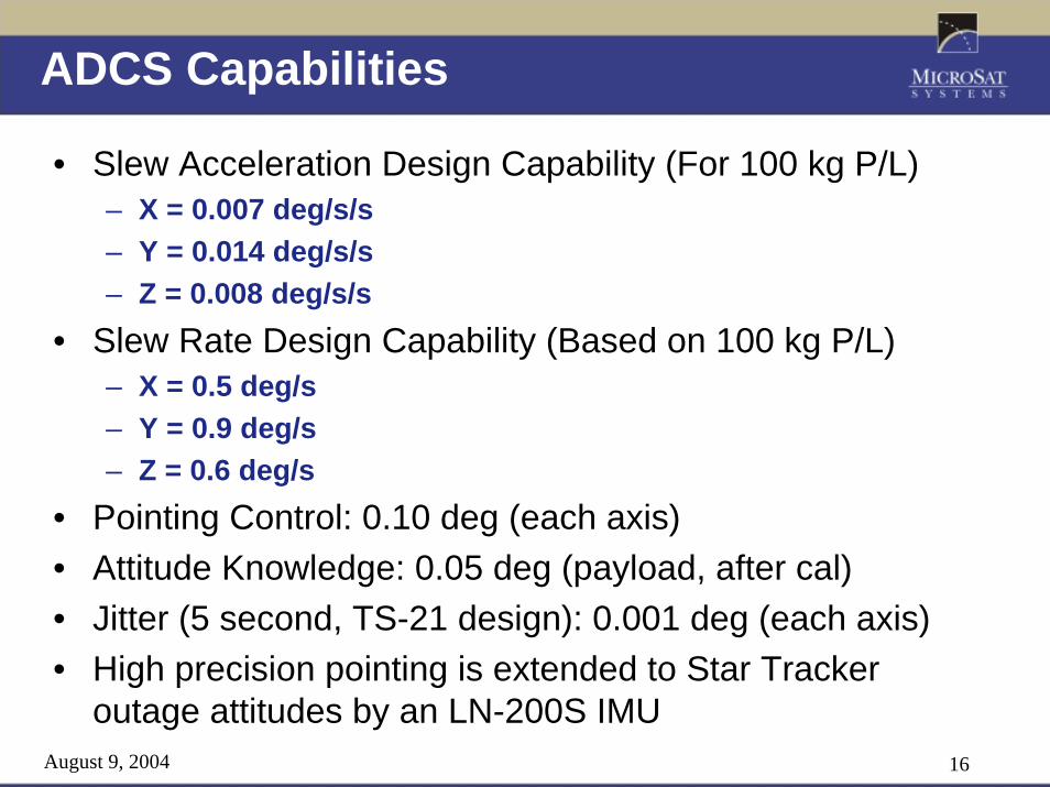
• Slew Acceleration Design Capability (For 100 kg P/L)– X = 0.007 deg/s/s– Y = 0.014 deg/s/s– Z = 0.008 deg/s/s
• Slew Rate Design Capability (Based on 100 kg P/L)– X = 0.5 deg/s – Y = 0.9 deg/s– Z = 0.6 deg/s
• Pointing Control: 0.10 deg (each axis)• Attitude Knowledge: 0.05 deg (payload, after cal)• Jitter (5 second, TS-21 design): 0.001 deg (each axis)• High precision pointing is extended to Star Tracker
outage attitudes by an LN-200S IMU
August 9, 2004 17
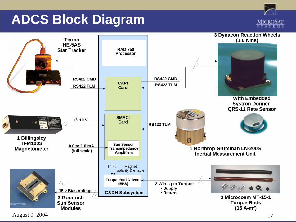
ADCS Block Diagram
Torque Rod Drivers(EPS)
+/- 10 V3
Sun Sensor Transimpedance
Amplifiers
3
0.0 to 1.0 mA(full scale)
C&DH Subsystem
3 Magnetpolarity & enable
RAD 750Processor
RS422 CMD
2 Wires per Torquer• Supply• Return
RS422 CMD
SMACICard
3
3
TermaHE-5AS
Star Tracker
1 BillingsleyTFM100S
Magnetometer
3 GoodrichSun Sensor
Modules
3 Dynacon Reaction Wheels(1.0 Nms)
3 Microcosm MT-15-1Torque Rods
(15 A-m2)
CAPICardRS422 TLM
RS422 TLM
RS422 TLM
15 v Bias Voltage3
With EmbeddedSystron Donner
QRS-11 Rate Sensor
1 Northrop Grumman LN-200S Inertial Measurement Unit

August 9, 2004 18
Thermal Control System• TCS Capabilities
– Can support an orbit average of 224W of internal load dissipation
– Maintains Bulk Spacecraft Temperature below 25°C in hot case and above 10oC in Cold Case
– TCS supports: • 48 AD590 Temperature Sensors• 8 Platinum Resistance Thermistors• 6 Software-Controlled Heater Zones (3 for bus, 3 for payloads)
with mode-dependent set points– Passive design, no active components except heaters

August 9, 2004 19
S-Band Communications
MCU-100 Tlm, Data, Gate& Clk(RS-422)
IAUCAPI Card
RF Switch
AFSCNTriplexer
Zenith SGLSAntenna
Uplink Clk & DataRS-422 @ 50KHz
Zenith TDRSSAntenna
NADIRSGLS
Antenna
DownlinkRS-422 Clk & Data
T&CRS-422 Data @ 230.4Kbaud
Un-switched Essential Bus + 28 VDC
IAU PAPI Card
Power Splitter/ Combiner
Uplink Rcvr Input (1799.556 MHz)
TDRSS Rcvr Input (2106.40 MHz)
Switched + 28 VDC for Downlink Xmtr
LPT Electronics
Box
Mini- COMSEC Unit (MCU-100)
Temp Sensors(3- AD590)
CT Data (4-RS-422)
Un-switched Essential Bus + 28 VDC
LPT Reset(RS-422)
Downlink Xmtr (2247.50 MHz SGLS or 2287.5 MHz TDRSS)
New LPT Componentsin Tan
RF SwitchTransfer Switch
PSL Helix Antenna5.7” High 4” Dia.
TDRSSTriplexer
MCU Reset(RS-422)
IGOR GPS Antenna
GPS L1
GPS L2
GPSDiplexer
PowerSplitter/
Combiner
To IGOR GPS Rcvr

August 9, 2004 20
C&DH (Broad Reach IAU) Capabilities
Resource/Feature Capabilities Available to P/LProcessor BAE Rad750 (Power PC Based)
Analog Voltage/Current Sensors 2228V Timed Switches 928V Low Power SW Outputs 7 (3 Arm-Fire, 4 Fire-Only)28V High Power SW Outputs 33 (4 Arm-Fire, 29 Fire-Only)
S/C Commanding HW & SW commands, CCSDS FormatNon-Volatile Memory 16MBytesVolatile Memory 640MBytes (128M CPU + 512M CASI)LVDS interfaces 2 Mux’ed Inputs
TTL Discrete In 10TTL Discrete Out 16
RS422 interfaces 26 RX, 2632 TX

August 9, 2004 21
Propulsion• Busek Tandem Hall Thruster (BHT-200-X3)
– http://www.busek.com/low_power.htm• 4.5 kg of Propellant Nominal Load
– Propellant mass may be increased by either adding a second tank or modifying regulator and loading Xenon at the launch site to avoid DOT tank safety factor limits
• Typical operation is at 1300 sec, 11 mN, 330 W • Isp selectable from 1200-1600 sec• Wattage selectable from 50-330 W• Thrust is up to 12.5 mN
August 9, 2004 22
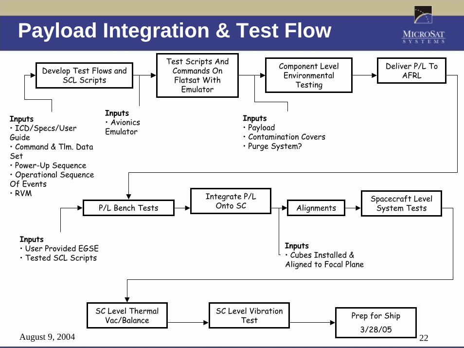
Payload Integration & Test Flow
Develop Test Flows and SCL Scripts
Inputs• ICD/Specs/User Guide• Command & Tlm. Data Set• Power-Up Sequence• Operational Sequence Of Events• RVM
P/L Bench TestsIntegrate P/L
Onto SC
Deliver P/L To AFRL
Inputs• User Provided EGSE• Tested SCL Scripts
Prep for Ship
3/28/05
Spacecraft Level System Tests
SC Level Thermal Vac/Balance
SC Level Vibration Test
Inputs• Payload• Contamination Covers• Purge System?
Alignments
Component Level Environmental
Testing
Test Scripts And Commands On Flatsat With
Emulator
Inputs• Avionics Emulator
Inputs• Cubes Installed & Aligned to Focal Plane
August 9, 2004 23
Lessons Learned• Fewer Organizations Lead to Streamlined
Communications• Simplified Requirements Allow Limited Manpower to
Focus on the Most Important Aspects• Adequately Funding Programs and Allowing the Major
Players to All Get Under Contract Before Starting Detailed Design is Much More Efficient Than the Alternative
• Optimize Work Time by Minimizing Meetings and Keeping Most of Those as Working Meetings
• Capabilities Driven Approach Greatly Reduces the Necessity of Redesign to Accommodate Changes
August 9, 2004 24
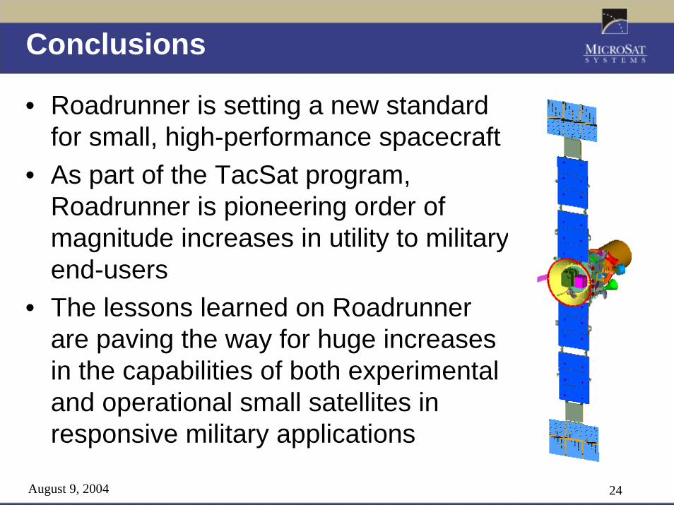
Conclusions
• Roadrunner is setting a new standard for small, high-performance spacecraft
• As part of the TacSat program, Roadrunner is pioneering order of magnitude increases in utility to military end-users
• The lessons learned on Roadrunner are paving the way for huge increases in the capabilities of both experimental and operational small satellites in responsive military applications