Embed Size (px)
Citation preview

trackroadtriathlonmtbTechnical Manual2008wheelsrimssystemsaccessories
more atwww.mavic.coma better bike begins here

02
2008CONTENTS
INTRODUCTION / MAVIC® CUSTOMER SERVICE
MAVIC WHEELSSEGMENTATION OF THE WHEEL RANGE / GENERAL POINTSAKSIUM 08KSYRIUM ÉQUIPE 08KSYRIUM SL 08 (CLINCHER VERSION)KSYRIUM SL 08 (TUBULAR VERSION)KSYRIUM SL PREMIUMR-SYS (CLINCHER VERSION)R-SYS (TUBULAR VERSION)COSMIC CARBONE ULTIMATECROSSRIDE UBCROSSRIDE UB DISC 08CROSSTRAIL LEFTYCROSSMAX 29’’CROSSMAX 29’ 20 MMCROSSMAX ST DISC 20 MMCROSSMAX ST LEFTYCROSSMAX ST LEFTY LTDWHEEL MAINTENANCEHUB MAINTENANCEWHEEL BUILDING / REPLACING SPOKES AND RIMS
MAVIC RIMSSEGMENTATION OF THE RANGEGENERAL POINTSNEW RIMS FOR 2008: TN 719 DISC, EN 521 DISC
SYSTEMS & ACCESSORIESWINTECH ALTIWINTECH E-BOLT PROGRAMMING / USE / INSTALLATION
TOOLS AND CUSTOMER SERVICEMAVIC TOOLSGENERAL PROCEDURE FOR ALL SERVICE SUPPORT REQUESTSWARRANTY AND MAVIC CUSTOMER SERVICE / CONTACTING YOUR MSC
03.
04>36.04.05.06.07.08.09.10.11.12.13.14.15.16.17.18.19.20.
22>32.23>24.25>32.
33>35.
33.34.35.
36>40.
38.39.40.
41>45.41>43.
44.45.
THIS DOCUMENT ONLY CONCERNS 2008 NEW PRODUCTS.
THIS DOCUMENT UPDATES THE EXISTING TECHNICAL INFORMATION AND SHOULD THEREFORE BE KEPT IN A SAFE PLACE FOR AN UNLIMITED LENGTH OF TIME ALONG WITH THE MANUALS FROM PREVIOUS YEARS.
ALL THE INFORMATION CONCERNING THE EXISTING PRODUCTS IN THE PREVIOUS RANGES CAN BE FOUND IN THE TECHNICAL MANUALS PRINTED SINCE 1997.
YOU CAN GO ON-LINE TO THE WWW.TECH-MAVIC.COM WEBSITE TO FIND ALL THE EDITIONS OF THIS MANUAL SINCE 1997.

03
THE NEW 2008 TECHNICAL MANUAL
• WHEELS• RIMS• SYSTEMS AND ACCESSORIES• TOOLS AND CUSTOMER SERVICE
You will find two types of technical information in each of these parts:• Product drawings showing individual part numbers;• Procedures to properly maintain our products as well as those to follow concerning the warranty and Mavic Service Centers.
As we have already mentioned, this document only offers technical information regarding the modifications of the existing products and new products in the 2008 range. It therefore concerns:
• The following wheels: Aksium, Ksyrium Équipe 08, Ksyrium SL 08, Ksyrium SL Premium, R-Sys, Cosmic Carbone Ultimate, Crossride UB, Crossride 08, Crosstrail Lefty, C29ssmax, Crossmax ST Lefty, Crossmax ST 20 mm.
• The following rims: TN 719 Disc, EN 521 Disc.• The following components: Wintech E-Bolt, Wintech Alti.
We hope this document will meet your needs and we are always open to listen to any suggestions to improve on it.
Thank you for your confidence in us and have a good 2008 season.
MAVIC CUSTOMER SERVICE
Our objective is that you be the only service partner for the customer.
You are also assured that through the use of our world wide Mavic Service Center (MSC), you will benefit from maximum assistance, the best possible service and professional advice.
Mavic MSC is at your disposal to guide you through the necessary procedures in the event you need to return a part, make repairs, make standard replacements, or to send you spare parts needed for product maintenance.
We simply ask that you contact your MSC prior to all returns (see page 45), to obtain the proper return procedures. Mavic will only accept authorized returns.
For further information, contact your MSC or consult the end pages of this technical manual.
www.tech-mavic.comThis website (in French and English) is at your complete disposal. Every bit of information about Mavic products released since 1997 is available in PDF format, in both English and French.
Visit: www.tech-mavic.com where you will find all of this information. To connect to this website you will need a login and password:
User name: mavic-comPassword: dealer
Among other things on the website, you will find:
• All the technical details on all the Mavic products marketed since 1997 - wheels, rims, components – organised by discipline and by product;
• 4 recap charts of spoke lengths and references for all our wheels, which will help you to manage your spoke stock;
• A program for calculating spoke length: starting with a given Mavic rim, select the drilling and lacing pattern, the width of your hub, as well as the diameter of the flanges and the distance between the flanges and the frame or fork support; the spoke length required for building your wheel will automatically be calculated.
We hope that this tool will meet your needs. Do not hesitate to inform us of any malfunctioning or improvements that you would like to see.
THE 2008 TECHNICAL MANUAL IS ESSENTIAL FOR ENSURING THE MAINTENANCE OF MAVIC PRODUCTS. IT CONSISTS OF 4 MAIN PARTS:
RETAILERCUSTOMER MSC
04
MAVIC® WHEELS
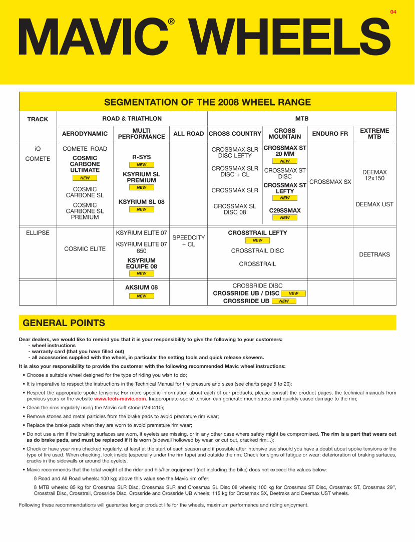
Dear dealers, we would like to remind you that it is your responsibility to give the following to your customers:- wheel instructions- warranty card (that you have filled out)- all accessories supplied with the wheel, in particular the setting tools and quick release skewers.
It is also your responsibility to provide the customer with the following recommended Mavic wheel instructions:
• Choose a suitable wheel designed for the type of riding you wish to do;
• It is imperative to respect the instructions in the Technical Manual for tire pressure and sizes (see charts page 5 to 20);
• Respect the appropriate spoke tensions; For more specific information about each of our products, please consult the product pages, the technical manuals from previous years or the website www.tech-mavic.com. Inappropriate spoke tension can generate much stress and quickly cause damage to the rim;
• Clean the rims regularly using the Mavic soft stone (M40410);
• Remove stones and metal particles from the brake pads to avoid premature rim wear;
• Replace the brake pads when they are worn to avoid premature rim wear;
• Do not use a rim if the braking surfaces are worn, if eyelets are missing, or in any other case where safety might be compromised. The rim is a part that wears out as do brake pads, and must be replaced if it is worn (sidewall hollowed by wear, or cut out, cracked rim…);
• Check or have your rims checked regularly, at least at the start of each season and if possible after intensive use should you have a doubt about spoke tensions or the type of tire used. When checking, look inside (especially under the rim tape) and outside the rim. Check for signs of fatigue or wear: deterioration of braking surfaces, cracks in the sidewalls or around the eyelets.
• Mavic recommends that the total weight of the rider and his/her equipment (not including the bike) does not exceed the values below:
ß Road and All Road wheels: 100 kg; above this value see the Mavic rim offer;
ß MTB wheels: 85 kg for Crossmax SLR Disc, Crossmax SLR and Crossmax SL Disc 08 wheels; 100 kg for Crossmax ST Disc, Crossmax ST, Crossmax 29’’, Crosstrail Disc, Crosstrail, Crossride Disc, Crossride and Crossride UB wheels; 115 kg for Crossmax SX, Deetraks and Deemax UST wheels.
Following these recommendations will guarantee longer product life for the wheels, maximum performance and riding enjoyment.
SEGMENTATION OF THE 2008 WHEEL RANGE
TRACK
iO
COMETE
ROAD & TRIATHLON
AERODYNAMIC MULTI PERFORMANCE ALL ROAD
COSMICCARBONE ULTIMATE
CROSS COUNTRY CROSSMOUNTAIN
EXTREME MTB
CROSSMAX SLR DISC LEFTY
DEEMAX UST
CROSSMAX SLRDISC + CL
CROSSMAX SLR
CROSSMAX ST 20 MM
CROSSTRAIL LEFTY
CROSSTRAIL DISC
CROSSTRAIL
KSYRIUM ELITE 07SPEEDCITY
+ CL
ELLIPSE
COSMIC ELITE
NEW
KSYRIUMEQUIPE 08
GENERAL POINTS
COMETE ROAD
MTB
COSMICCARBONE SL
KSYRIUM ELITE 07 650
CROSSRIDE UB / DISC NEW
DEEMAX12x150
DEETRAKS
AKSIUM 08
CROSSMAX SX
ENDURO FR
COSMICCARBONE SL
PREMIUM
NEW
CROSSMAX SL DISC 08
NEW
NEW
NEW
CROSSRIDE DISC
R-SYSNEW
KSYRIUM SL PREMIUM
NEW
KSYRIUM SL 08NEW
NEW
CROSSMAX ST DISC
CROSSMAX ST LEFTY
C29SSMAXNEW
CROSSRIDE UB NEW

05
323 484 01
323 482 01
M40578
995 000 01
M40067 M40592 (M10)M40591 (ED10)
M40660
323 479 01
M40318
323 484 01
WHEEL BUILDING
Black:Front + rear non-drive side: Drive side:
Silver:Front + rear non-drive side: Drive side:
FEATURES: Black steel or silver stainless steel, bladed straight pull spokes with ABS nipples
LACING PATTERN:Front: radialRear: crossed 2 drive side, radial non-drive side
AKSIUM 08USE: use only on a road bike. Any other use (such as on a tandem, cyclo-cross bike, or off-road use…) is strongly inadvisable, is the sole responsibility of the user and voids the Mavic warranty.
BLACK WHEEL REFERENCES:Front: 995 660 10Rear M10: 996 661 11Rear ED10: 995 662 12Pair M10: 995 664 14Pair ED10: 995 663 14
RIMS
HUBSMAINTENANCE: Clean with a dry cloth or soap and water.
Do not use pressurized water.
SALES REFERENCES: Black: 996 092 15 (front and rear) Silver: 996 093 15 (front and rear)
RECOMMENDED TIRE WIDTH AND PRESSUREVALVE HOLE Ø
Dimensions: ETRTO 622 x 15C Recommended tire width: 19 to 32 mm
Recommended tire pressure:See page 21
Ø: 6.5 mmLength: ! 32 mm
WHEEL WEIGHTS WITHOUT QUICK RELEASE SKEWER:Front: 870 gRear M10: 1000 gRear ED10: 985 g
SILVER WHEEL REFERENCES:Front: 995 581 10Rear M10: 995 582 11Rear ED10: 995 652 12Pair M10: 995 653 14Pair ED10: 995 654 14
TENSION:Front: 80 to 90 kgRear drive side: 150 to 165 kg
As the front hub is made up of 3 parts, and the rear hub of 2 parts, maintenance operations to the hubs (replacing the axle or bearings) must always be carried out on the assembled wheel (hub, rim and spokes assembled).
REFERENCES AND LENGTHS: 996 075 01, length 282.5 mm (per 10, with nipples)
996 076 01, length 305 mm (per 10, with nipples)
996 077 01, length 282.5 mm (per 10, with nipples)996 078 01, length 305 mm (per 10, with nipples)
ACCESSORIES MAINTENANCEWHEELS SUPPLIED WITH:
• Traditional aluminum front quick release skewer M40350• Traditional aluminum rear quick release skewer M40351• ED10 12D locking ring M40640 (with rear wheel ED10)• Rim tape• User guide and warranty card
Replacing the front axle and bearingsReplacing the rear axleMaintaining and replacing the free wheel mechanismReplacing the rear bearingsReplacing a spokeReplacing the front rimReplacing the rear rim
To quickly consult this information in a practical manner, refer to www.tech-mavic.com
See 2004 TM page 19See 2004 TM page 20See 2004 TM page 21See 2004 TM page 22 See page 25See page 25See page 26

06
M40067
996 038 01M40578 995 000 01
996 039 01 M40660
M40591 (ED10)M40592 (M10)
996 038 01
M40318996 037 01
WHEEL BUILDING
ACCESSORIES MAINTENANCE
Black front: Black drive side: Black non-drive side:Silver front:Silver drive side:Silver non-drive side:
WHEELS SUPPLIED WITH:
FEATURES: Black or silver stainless steel, bladed straight pull spokes with ABS nipples
• Traditional aluminum front quick release skewer M40350• Traditional aluminum rear quick release skewer M40351• ED10 12D locking ring M40640 (with rear wheel ED10)• Rim tape• User guide and warranty card
Replacing the front axle and bearingsReplacing the rear axleMaintaining and replacing the free wheel mechanismReplacing the rear bearingsReplacing a spokeReplacing the front rimReplacing the rear rim
LACING PATTERN:Front: radialRear: Isopulse
KSYRIUM EQUIPE 08USE: use only on a road bike. Any other use (such as on a tandem, cyclo-cross bike, or off-road use…) is strongly inadvisable, is the sole responsibility of the user and voids the Mavic warranty.
BLACK WHEEL REFERENCES
Front:Rear M10:Rear ED10:Pair M10:Pair ED10:
RIMS
HUBSMAINTENANCE: Clean with a dry cloth or soap and water.
Do not use pressurized water.
Black Front:Rear:
996 050 10996 050 13
Siver Front:Rear:
996 051 10996 051 13
RECOMMENDED TIRE WIDTH AND PRESSUREVALVE HOLE Ø
Dimensions: ETRTO 622 x 15C Recommended tire width: 19 to 28 mm
Recommended tire pressure:See page 21
Ø: 6.5 mmLength: ! 32 mm
TENSION:Front: 80 to 90 kgRear drive side: 130 to 145 kg
As the front hub is made up of 3 parts, maintenance operations to the hubs (replacing the axle or bearings) must always be carried out on the assembled wheel (hub, rim and spokes assembled).
REFERENCES AND LENGTHS:
996 057 01, length 278 mm (per 9, with nipples)996 058 01, length 274 mm (per 10, with nipples)996 059 01, length 298.5 mm (per 10, with nipples)996 060 01, length 278 mm (per 9, with nipples)996 061 01, length 274 mm (per 10, with nipples)996 062 01, length 298.5 mm (per 10, with nipples)
WORLD996 110 10996 111 11996 112 12995 507 14996 113 14
USA995 504 10996 505 11995 506 12995 507 14995 508 14
SILVER WHEEL REFERENCES
Front:Rear M10:Rear ED10:Pair M10:Pair ED10:
WORLD996 114 10996 115 11996 116 12995 715 14996 717 14
USA995 704 10995 708 11995 709 12995 715 14995 716 14
SALES REFERENCES:
To quickly consult this information in a practical manner, refer to www.tech-mavic.com
See 2004 TM page 19See 2004 TM page 20See 2004 TM page 21See 2004 TM page 22 See page 25See page 25See page 27
WHEEL WEIGHTS WITHOUT QUICK RELEASE SKEWER:Front:Rear M10:Rear ED10:
810 g975 g960 g

07
M40078
M40052
995 000 01M40063
M40676
995 000 01M40067 M40592 (M10)
M40591 (ED10)
995 937 01M40075
M40578
324 130 01
WHEEL BUILDING
ACCESSORIES MAINTENANCE
Front: Drive side: Non-drive side:
WHEELS SUPPLIED WITH:
FEATURES: Black Zicral bladed straight pull spokes with integrated M7 nipples (self-locking)
• BR 601 front quick release skewer M40149• BR 601 rear quick release skewer M40150• Computer magnet M40540 (with front wheel)• Free play adjustment wrench M40123 (with rear wheel)• Spoke wrench M40494 (with rear wheel)• ED10 12D locking ring M40640 (with rear wheel ED10)• User guide and warranty card
Replacing the front axle and bearingsReplacing the rear axleMaintaining and replacing the free wheel mechanismReplacing the rear bearingsReplacing a spokeReplacing the front rimReplacing the rear rim
LACING PATTERN:Front: radialRear: Isopulse
KSYRIUM SL 08 (clincher version)
USE: use only on a road bike. Any other use (such as on a tandem, cyclo-cross bike, or off-road use…) is strongly inadvisable, is the sole responsibility of the user and voids the Mavic warranty.
RIMS
HUBSMAINTENANCE: Clean with a dry cloth or soap and water.
Do not use pressurized water.
Clincher Front:Rear:
996 054 10996 054 13
RECOMMENDED TIRE WIDTH AND PRESSUREVALVE HOLE Ø
Dimensions: ETRTO 622 x 15C Recommended tire width: 19 to 28 mm
Recommended tire pressure:See page 21
Ø: 6.5 mmLength: ! 32 mm
WHEEL WEIGHTS WITHOUT QUICK RELEASE SKEWER:Front:Rear M10:Rear ED10:
TENSION:Front: 110 to 130 kgRear drive side: 120 to 140 kg
REFERENCES AND LENGTHS:
324 178 01, length 284.5 mm (per 11, integrated nipples)324 179 01, length 275 mm (per 10, integrated nipples)324 180 01, length 298.5 mm (per 10, integrated nipples)
WHEEL REFERENCES:
Front:Rear M10:Rear ED10:Pair M10:Pair ED10:
SALES REFERENCES:
To quickly consult this information in a practical manner, refer to www.tech-mavic.com
See 2005 TM page 20See 2007 TM page 20See 2003 TM page 21See 2003 TM page 22 See 2003 TM page 23See 2003 TM page 27See 2007 TM page 17
645 g855 g840 g
WORLD996 118 10996 119 11996 120 12995 720 14996 121 14
USA995 717 10995 718 11995 719 12995 720 14995 721 14
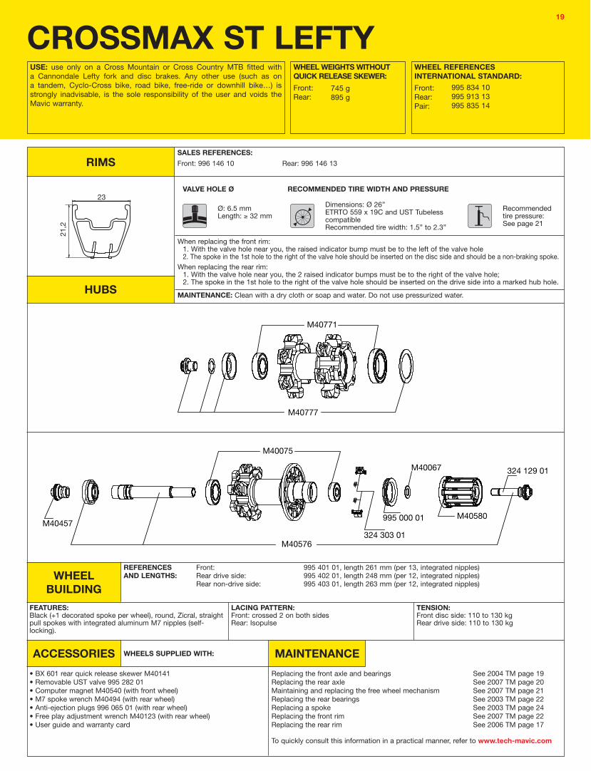
When replacing the rear rim: 1. With the valve hole near you, the 2 raised indicator bumps must be to the right of the valve hole;2. The spoke in the 1st hole to the right of the valve hole should be inserted on the drive side into a marked hub hole.

08
M40676
995 000 01M40067 M40592 (M10)
M40591 (ED10)
995 937 01M40075
M40578
324 130 01
M40078
M40052
995 000 01M40063
9
20,5
229
20,5
22
WHEEL BUILDING
ACCESSORIES MAINTENANCE
Front: Drive side: Non-drive side:
WHEELS SUPPLIED WITH:
FEATURES: Black Zicral bladed straight pull spokes with integrated M7 nipples (self-locking)
• BR 601 front quick release skewer M40149• BR 601 rear quick release skewer M40150• Computer magnet M40540 (with front wheel)• Free play adjustment wrench M40123 (with rear wheel)• Spoke wrench M40494 (with rear wheel)• ED10 12D locking ring M40640 (with rear wheel ED10)• User guide and warranty card
Replacing the front axle and bearingsReplacing the rear axleMaintaining and replacing the free wheel mechanismReplacing the rear bearingsReplacing a spokeReplacing the front rimReplacing the rear rim
LACING PATTERN:Front: radialRear: Isopulse
KSYRIUM SL 08 (tubular version)
USE: use only on a road bike. Any other use (such as on a tandem, cyclo-cross bike, or off-road use…) is strongly inadvisable, is the sole responsibility of the user and voids the Mavic warranty.
RIMS
HUBSMAINTENANCE: Clean with a dry cloth or soap and water.
Do not use pressurized water.
Tubular Front:Rear:
996 055 10996 055 13
RECOMMENDED TIRE WIDTH AND PRESSUREVALVE HOLE Ø
Dimensions: Ø 700622 tubular onlyRecommended tubular width: 19 to 23 mm
Recommended tire pressure:See page 21
Ø: 6.5 mmLength: ! 32 mm
WHEEL WEIGHTS WITHOUT QUICK RELEASE SKEWER:Front:Rear M10:Rear ED10:
TENSION:Front: 110 to 130 kgRear drive side: 120 to 140 kg
REFERENCES AND LENGTHS:
324 178 01, length 284.5 mm (per 11, integrated nipples)996 152 01, length 278 mm (per 10, integrated nipples)996 153 01, length 301.5 mm (per 10, integrated nipples)
WHEEL REFERENCES:
Front:Rear M10:Rear ED10:
SALES REFERENCES:
To quickly consult this information in a practical manner, refer to www.tech-mavic.com
See 2005 TM page 20See 2007 TM page 20See 2003 TM page 21See 2003 TM page 22 See 2003 TM page 23See 2003 TM page 27See 2007 TM page 17
645 g830 g815 g
WORLD995 727 10995 728 11996 122 12
USA995 727 10995 728 11995 729 12
When replacing the rear rim: 1. With the valve hole near you, the 2 raised indicator bumps must be to the right of the valve hole;2. The spoke in the 1st hole to the right of the valve hole should be inserted on the drive side into a marked hub hole.

09
M40078
M40052
995 000 01M40063
M40676
995 000 01
M40067
M40592 (M10)M40591 (ED10)
996 044 01M40075
M40578
995 469 01
WHEEL BUILDING
ACCESSORIES MAINTENANCE
Front: Drive side: Non-drive side:
WHEELS SUPPLIED WITH:
FEATURES: Black Zicral bladed straight pull spokes with integrated M7 nipples (self-locking)
• BR 601 Titanium front quick release skewer 323 485 01• BR 601 Titanium rear quick release skewer 323 486 01• Computer magnet M40540 (with front wheel)• Free play adjustment wrench M40123 (with rear wheel)• Spoke wrench M40494 (with rear wheel)• ED10 12D locking ring M40640 (with rear wheel ED10)• Wheel bags M40135• User guide and warranty card
Replacing the front axle and bearingsReplacing the rear axleMaintaining and replacing the free wheel mechanismReplacing the rear bearingsReplacing a spokeReplacing the front rimReplacing the rear rim
LACING PATTERN:Front: radialRear: Isopulse
KSYRIUM SL PREMIUMUSE: use only on a road bike. Any other use (such as on a tandem, cyclo-cross bike, or off-road use…) is strongly inadvisable, is the sole responsibility of the user and voids the Mavic warranty.
RIMS
HUBSMAINTENANCE: Clean with a dry cloth or soap and water.
Do not use pressurized water.
Clincher Front:Rear:
996 056 10996 056 13
RECOMMENDED TIRE WIDTH AND PRESSUREVALVE HOLE Ø
Dimensions: ETRTO 622 x 15C Recommended tire width: 19 to 28 mm
Recommended tire pressure:See page 21
Ø: 6.5 mmLength: ! 32 mm
WHEEL WEIGHTS WITHOUT QUICK RELEASE SKEWER:Front:Rear M10:Rear ED10:
TENSION:Front: 110 to 130 kgRear drive side: 120 to 140 kg
REFERENCES AND LENGTHS:
324 178 01, length 284.5 mm (per 11, integrated nipples)324 179 01, length 275 mm (per 10, integrated nipples)324 180 01, length 298.5 mm (per 10, integrated nipples)
WHEEL REFERENCES:
Front:Rear M10:Rear ED10:Pair M10:Pair ED10:
SALES REFERENCES:
To quickly consult this information in a practical manner, refer to www.tech-mavic.com
See 2005 TM page 20See 2007 TM page 20See 2003 TM page 21See 2003 TM page 22 See 2003 TM page 23See 2003 TM page 27See 2007 TM page 17
645 g850 g835 g
WORLD996 129 10996 130 11996 131 12995 894 14996 132 14
USA995 891 10996 892 11995 893 12995 894 14995 895 14
When replacing the rear rim: 1. With the valve hole near you, the 2 raised indicator bumps must be to the right of the valve hole;2. The spoke in the 1st hole to the right of the valve hole should be inserted on the drive side into a marked hub hole.

10
996 043 01
M40078
996 041 01
M40063
M40052
996 035 01996 043 01 M40578
M40077
996 042 01
995 000 01M40067
M40592 (M10)M40591 (ED10)
324 130 01
WHEEL BUILDING
ACCESSORIES MAINTENANCE
Front: Drive side: Non-drive side:
WHEELS SUPPLIED WITH:
FEATURES: Front and rear non-drive side: carbon tubular spokes (Tracomp)Rear drive side: black Zicral bladed straight pull spokes with integrated M7 nipples (self-locking)
• BR 601 front quick release skewer M40149• BR 601 rear quick release skewer M40150• Computer magnet integrated into spoke (front wheel)• Free play adjustment wrench M40123 (with rear wheel)• Spoke wrench 996 079 01 (with rear wheel)• Spoke wrench M40567 (with rear wheel)• Tracomp ring tool 996 080 01• ED10 12D locking ring M40640 (with rear wheel ED10)• Wheel bags M40135• User guide and warranty card
Replacing the front axle and bearingsReplacing the rear axleMaintaining and replacing the free wheel mechanismReplacing the rear bearingsImportant note for fitting Tracomp spokesIdentifying a damaged Tracomp carbon spokeRemoving / Refitting the Tracomp ringTruing and replacing a Tracomp spokeReplacing the front rimReplacing the rear rim
LACING PATTERN:Front: radial, Tracomp systemRear: crossed 2 drive side, radial non-drive side, Tracomp system
R-SYS (clincher version)USE: use only on a road bike. Any other use (such as on a tandem, cyclo-cross bike, or off-road use…) is strongly inadvisable, is the sole responsibility of the user and voids the Mavic warranty.
RIMS
HUBSMAINTENANCE: Clean with a dry cloth or soap and water.
Do not use pressurized water.
Clincher Front:Rear:
996 052 10996 052 13
RECOMMENDED TIRE WIDTH AND PRESSUREVALVE HOLE Ø
Dimensions: ETRTO 622 x 15C Recommended tire width: 19 to 28 mm
Recommended tire pressure:See page 21
Ø: 6.5 mmLength: ! 32 mm
WHEEL WEIGHTS WITHOUT QUICK RELEASE SKEWER:Front:Rear M10:Rear ED10:
TENSION:Front: 55 to 70 kgRear drive side: 90 to 110 kg
REFERENCES AND LENGTHS:
107 955 01, length 285 mm (per 9, integrated nipples)996 073 01, length 294.5 mm (per 10, integrated nipples)107 956 01, length 283.7 mm (per 10, integrated nipples)
WHEEL REFERENCES:
Front:Rear M10:Rear ED10:Pair M10:Pair ED10:
SALES REFERENCES:
To quickly consult this information in a practical manner, refer to www.tech-mavic.com
See 2005 TM page 20See page 24See 2003 TM page 21See page 24 See page 28See page 28See page 29See page 30See page 30See page 31
570 g800 g785 g
WORLD996 123 10996 124 11996 125 12995 475 14996 126 14
USA995 472 10995 473 11995 474 12995 475 14995 486 14
When replacing the rear rim: 1. With the valve hole near you, the 2 raised indicator bumps must be to the right of the valve hole;2. The spoke in the 1st hole to the right of the valve hole should be inserted on the drive side and should be a non-traction spoke.
Never turn a Tracomp spoke nipple without having first removed the Tracomp rings from the hub, otherwise the spoke may be irreversibly damaged.Never fit another computer magnet other than the one integrated.Only transport the wheels in the wheel bags supplied. Avoid side shocks to the Tracomp spokes.

11
9
20,5
229
20,5
22
996 043 01
M40078
996 041 01
M40063
M40052
996 035 01996 043 01 M40578
M40077
996 042 01
995 000 01M40067
M40592 (M10)M40591 (ED10)
324 130 01
WHEEL BUILDING
ACCESSORIES MAINTENANCE
Front: Drive side: Non-drive side:
WHEELS SUPPLIED WITH:
FEATURES: Front and rear non-drive side: carbon tubular spokes (Tracomp)Rear drive side: black Zicral bladed straight pull spokes with integrated M7 nipples (self-locking)
• BR 601 front quick release skewer M40149• BR 601 rear quick release skewer M40150• Computer magnet integrated into spoke (front wheel)• Free play adjustment wrench M40123 (with rear wheel)• Spoke wrench 996 079 01 (with rear wheel)• Spoke wrench M40567 (with rear wheel)• Tracomp ring tool 996 080 01• ED10 12D locking ring M40640 (with rear wheel ED10)• Wheel bags M40135• User guide and warranty card
Replacing the front axle and bearingsReplacing the rear axleMaintaining and replacing the free wheel mechanismReplacing the rear bearingsImportant note for fitting Tracomp spokesIdentifying a damaged Tracomp carbon spokeRemoving / Refitting the Tracomp ringTruing and replacing a Tracomp spokeReplacing the front rimReplacing the rear rim
LACING PATTERN:Front: radial, Tracomp systemRear: crossed 2 drive side, radial non-drive side, Tracomp system
R-SYS (tubular version)USE: use only on a road bike. Any other use (such as on a tandem, cyclo-cross bike, or off-road use…) is strongly inadvisable, is the sole responsibility of the user and voids the Mavic warranty.
RIMS
HUBSMAINTENANCE: Clean with a dry cloth or soap and water.
Do not use pressurized water.
Tubular Front:Rear:
996 053 10996 053 13
RECOMMENDED TIRE WIDTH AND PRESSUREVALVE HOLE Ø
Dimensions: Ø 700622 tubular onlyRecommended tubular width: 19 to 23 mm
Recommended tire pressure:See page 21
Ø: 6.5 mmLength: ! 32 mm
WHEEL WEIGHTS WITHOUT QUICK RELEASE SKEWER:Front:Rear M10:Rear ED10:
TENSION:Front: 55 to 70 kgRear drive side: 90 to 110 kg
REFERENCES AND LENGTHS:
107 955 01, length 285 mm (per 9, integrated nipples)996 151 01, length 297.5 mm (per 10, integrated nipples)107 957 01, length 286.7 mm (per 10, integrated nipples)
WHEEL REFERENCES:
Front:Rear M10:Rear ED10:
SALES REFERENCES:
To quickly consult this information in a practical manner, refer to www.tech-mavic.com
See 2005 TM page 20See page 24See 2003 TM page 21See page 24 See page 28See page 28See page 29See page 30See page 30See page 31
570 g775 g760 g
WORLD995 525 10995 526 11996 127 12
USA995 525 10995 526 11995 527 12
When replacing the rear rim: 1. With the valve hole near you, the 2 raised indicator bumps must be to the right of the valve hole;2. The spoke in the 1st hole to the right of the valve hole should be inserted on the drive side and should be a non-traction spoke.
Never turn a Tracomp spoke nipple without having first removed the Tracomp rings from the hub, otherwise the spoke may be irreversibly damaged.Never fit another computer magnet other than the one integrated.Only transport the wheels in the wheel bags supplied. Avoid side shocks to the Tracomp spokes.

12
996 032 01
M40063
M40078
996 033 01
M40077 995 000 01996 034 01
996 035 01
996 045 01
996 036 01 M40578
M40067
M40592 (M10)M40591 (ED10)
WHEEL BUILDING
ACCESSORIES MAINTENANCEWHEELS SUPPLIED WITH:
FEATURES: Unidirectional carbon fiber spokes molded to the rim, traditional nipples at rear on non-drive side only.
• BR 601 Titanium front quick release skewer 323 485 01• BR 601 Titanium rear quick release skewer 323 486 01• ED10 12D locking ring M40640 (with rear wheel ED10)• Wheel bags M40135• 2 pairs of Mavic brake pads for carbon rims.
HG/Sram/Mavic: 995 737 01, ED: 995 738 01.• Bearing adjustment wrench M40123.• User guide and warranty card
Replacing the front axle and bearingsReplacing the rear axleMaintaining and replacing the free wheel mechanismReplacing the rear bearingsReplacing a nipple
LACING PATTERN:Front and rear drive side: rim to rim “diameter” spoke, crossed 2.Rear non-drive side: radial
COSMIC CARBONE ULTIMATEUSE: use only on a road bike. Any other use (such as on a tandem, cyclo-cross bike, or off-road use…) is strongly inadvisable, is the sole responsibility of the user and voids the Mavic warranty.
RIMS
HUBS
RECOMMENDED TIRE WIDTH AND PRESSUREVALVE HOLE Ø
Dimensions: Ø 700622 tubular onlyRecommended tubular width: 19 to 23 mm
Recommended tire pressure:See page 21
Ø: 6,5 mmLength.: ! 55 mm
WHEEL WEIGHTS WITHOUT QUICK RELEASE SKEWER:Front:Rear M10:Rear ED10:
WHEEL REFERENCES:
Front:Rear M10:Rear ED10:Pair M10:Pair ED10:
To quickly consult this information in a practical manner, refer to www.tech-mavic.com
See 2005 TM page 20See page 23See 2003 TM page 21See page 24See page 32
520 g680 g665 g
995 005 10996 006 11995 007 12995 035 14995 036 14
Only use the Mavic brake pads for use with carbon rims supplied with the wheels.They are available separately under the references 995 737 01 (HG, Sram, Mavic) and 995 738 01 (ED).
Clean with dry cloth or soap and water. Do not use pressurized water.Do not pull or press the spokes whilst handling the quick release skewer.Do not transport on a bike rack.Only transport the wheels in the wheel bags supplied. Avoid side shocks to the spokes.
Only transport the wheels in the wheel bags supplied.Avoid side shocks to the Tracomp spokes.

13
323 484 01
323 483 01
995 000 01
M40067
M40592324 303 01
M40660
323 479 01
323 484 01
M40318
CROSSRIDE UBUSE: use only on a Cross Mountain or Cross Country MTB fitted with rim mounted brakes. Any other use (such as on a tandem, Cyclo-Cross bike, road bike, free-ride or downhill bike…) is strongly inadvisable, is the sole responsibility of the user and voids the Mavic warranty.
RIMS
HUBS
WHEEL WEIGHTS WITHOUT QUICK RELEASE SKEWER:Front:Rear:
WHEEL REFERENCES:
Front:Rear:Pair:
805 g945 g
WORLD996 108 10996 109 13995 500 14
USA995 498 10995 499 13995 500 14
Front and rear: 996 095 15
RECOMMENDED TIRE WIDTH AND PRESSUREVALVE HOLE Ø
Dimensions: Ø 26’’ETRTO 559 x 17CRecommended tire width: 1.5 to 2.1
Recommended tire pressure:See page 21
Ø: 8.5 mm with 6.5 mm valve adapterLength: ! 32 mm
SALES REFERENCES:
MAINTENANCE: Clean with a dry cloth or soap and water.Do not use pressurized water.
WHEEL BUILDING
ACCESSORIES MAINTENANCE
Front + rear non-drive side:Drive side:
WHEELS SUPPLIED WITH:
FEATURES: Black steel straight pull bladed spokes with Self Lock system and traditional spoke nipples
• Traditional aluminum front quick release skewer: M40350• Traditional aluminum rear quick release skewer: M40351• Rim tape 559x20x0.6• User guide and warranty card
Replacing the front axle and bearingsReplacing the rear axleMaintaining and replacing the free wheel mechanismReplacing the rear bearingsReplacing a spokeReplacing the front rimReplacing the rear rim
LACING PATTERN:Front: radialRear: crossed 2 drive side, radial non-drive side
TENSION:Front: 100 to 120 kgRear drive side: 120 to 140 kg
REFERENCES AND LENGTHS:
996 069 01, length 253 mm (per 10, with nipples)996 070 01, length 276 mm (per 10, with nipples)
To quickly consult this information in a practical manner, refer to www.tech-mavic.com
See 2004 TM page 19See 2004 TM page 20See 2004 TM page 21See 2004 TM page 22 See page 25See page 25See page 26
As the front hub is made up of 3 parts, and the rear hub of 2 parts, maintenance operations to the hubs (replacing the axle or bearings) must always be carried out on the assembled wheel (hub, rim and spokes assembled).
14
32347901
32348401
M40318
323 484 01 M40660 324 303 01 995 000 01
M40067
M40592
323 480 01
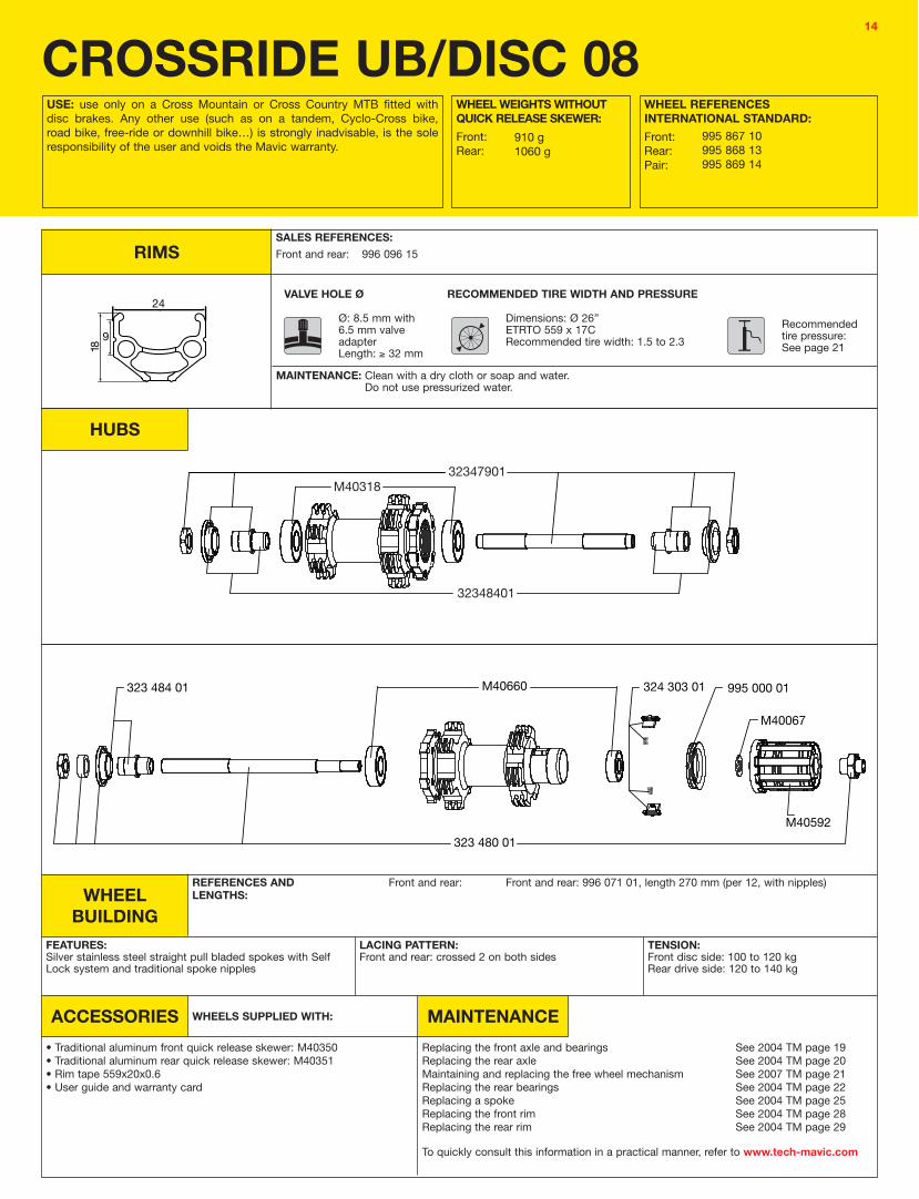
CROSSRIDE UB/DISC 08USE: use only on a Cross Mountain or Cross Country MTB fitted with disc brakes. Any other use (such as on a tandem, Cyclo-Cross bike, road bike, free-ride or downhill bike…) is strongly inadvisable, is the sole responsibility of the user and voids the Mavic warranty.
RIMS
HUBS
WHEEL WEIGHTS WITHOUT QUICK RELEASE SKEWER:Front:Rear:
WHEEL REFERENCES INTERNATIONAL STANDARD:Front:Rear:Pair:
910 g1060 g
995 867 10995 868 13995 869 14
Front and rear: 996 096 15
RECOMMENDED TIRE WIDTH AND PRESSUREVALVE HOLE Ø
Dimensions: Ø 26’’ETRTO 559 x 17CRecommended tire width: 1.5 to 2.3
Recommended tire pressure:See page 21
Ø: 8.5 mm with 6.5 mm valve adapterLength: ! 32 mm
SALES REFERENCES:
MAINTENANCE: Clean with a dry cloth or soap and water.Do not use pressurized water.
WHEEL BUILDING
ACCESSORIES MAINTENANCE
Front and rear:
WHEELS SUPPLIED WITH:
FEATURES: Silver stainless steel straight pull bladed spokes with Self Lock system and traditional spoke nipples
• Traditional aluminum front quick release skewer: M40350• Traditional aluminum rear quick release skewer: M40351• Rim tape 559x20x0.6• User guide and warranty card
Replacing the front axle and bearingsReplacing the rear axleMaintaining and replacing the free wheel mechanismReplacing the rear bearingsReplacing a spokeReplacing the front rimReplacing the rear rim
LACING PATTERN:Front and rear: crossed 2 on both sides
TENSION:Front disc side: 100 to 120 kgRear drive side: 120 to 140 kg
REFERENCES AND LENGTHS:
Front and rear: 996 071 01, length 270 mm (per 12, with nipples)
To quickly consult this information in a practical manner, refer to www.tech-mavic.com
See 2004 TM page 19See 2004 TM page 20See 2007 TM page 21See 2004 TM page 22See 2004 TM page 25See 2004 TM page 28See 2004 TM page 29

15
M40771
M40777
CROSSTRAIL LEFTYUSE: use only on a Cross Mountain or Cross Country MTB fitted with a Cannondale Lefty fork and disc brakes. Any other use (such as on a tandem, Cyclo-Cross bike, road bike, free-ride or downhill bike…) is strongly inadvisable, is the sole responsibility of the user and voids the Mavic warranty.
RIMS
HUBS
WHEEL WEIGHTS WITHOUT QUICK RELEASE SKEWER:Front:Rear:
WHEEL REFERENCES:
Front:Rear:Pair:
825 g975 g
995 838 10995 197 13995 839 14
Front: 995 418 10 Rear: 995 418 13
RECOMMENDED TIRE WIDTH AND PRESSUREVALVE HOLE Ø
Dimensions: Ø 26’’ETRTO 559 x 19C and UST Tubeless compatibleRecommended tire width: 1.5” to 2.3”
Recommended tire pressure:See page 21
Ø: 6.5 mmLength: ! 32 mm
SALES REFERENCES:
WHEEL BUILDING
ACCESSORIES MAINTENANCE
Front and rear:
WHEELS SUPPLIED WITH:
FEATURES: Black, bladed, stainless steel, straight pull spokes with integrated M7 nipples (self-locking).
• “Lefty” assembly accessories M40777 (front wheel)• Rear quick release skewer M40352• Removable UST valve 995 282 01• Wrench for aerodynamic spokes• User guide and warranty card
Fitting and removing the front wheel from the forkReplacing the front axle and bearingsReplacing the rear axleMaintaining and replacing the free wheel mechanismReplacing the rear bearingsReplacing a spokeReplacing the front rimReplacing the rear rim
LACING PATTERN:Front and rear: crossed 2 on both sides
TENSION:Front disc side: 100 to 120 kgRear drive side: 115 to 135 kg
REFERENCES AND LENGTHS:
995 419 01, length 273 mm (per 12, integrated nipples)
To quickly consult this information in a practical manner, refer to www.tech-mavic.com
See 2004 TM page 18See 2004 TM page 19See 2004 TM page 20See 2007 TM page 21See 2004 TM page 22See 2004 TM page 25See 2004 TM page 28See 2004 TM page 29
MAINTENANCE: Clean with a dry cloth or soap and water. Do not use pressurized water.
When replacing the front rim:1. With the valve hole near you, the raised indicator bump must be to the left of the valve hole2. The spoke in the 1st hole to the right of the valve hole should be inserted on the disc side and should be a non-braking spoke.
When replacing the rear rim:1. With the valve hole near you, the 2 raised indicator bumps must be to the right of the valve hole;2. The spoke in the 1st hole to the right of the valve hole should be inserted on the drive side and should be a non-traction spoke.

16
M40759
M40063
995 408 01M40052
M40318
M40457M40580
M40067
995 000 01
324 303 01M40576
M40075
324 129 01
C29SSMAXUSE: use only on a Cross Mountain or Cross Country MTB fitted with disc brakes. Any other use (such as on a tandem, Cyclo-Cross bike, road bike, free-ride or downhill bike…) is strongly inadvisable, is the sole responsibility of the user and voids the Mavic warranty.
RIMS
HUBS
WHEEL WEIGHTS WITHOUT QUICK RELEASE SKEWER:Front:Rear:
WHEEL REFERENCES INTERNATIONAL STANDARD:Front:Rear:Pair:
815 g935 g
995 856 10995 857 13995 858 14
Front: 996 063 10 Rear: 996 063 13
RECOMMENDED TIRE WIDTH AND PRESSUREVALVE HOLE Ø
Dimensions: Ø 29’’ETRTO 622 x 19C and UST Tubeless compatibleRecommended tire width: 1.5” to 2.3”
Recommended tire pressure:See page 21
Ø: 6.5 mmLength: ! 32 mm
SALES REFERENCES:
WHEEL BUILDING
ACCESSORIES MAINTENANCE
Front: Rear drive side:Rear non-drive side:
WHEELS SUPPLIED WITH:
FEATURES: Black (+1 decorated spoke per wheel), round, Zicral, straight pull spokes with integrated aluminum M7 nipples (self-locking).
• BX 601 front quick release skewer M40140• BX 601 rear quick release skewer M40141• Computer magnet M40540• M7 spoke wrench M40494 (with rear wheel)• UST valves 995 282 01• Anti-ejection plugs 996 065 01 (with rear wheel)• Free play adjustment wrench M40123 (with rear wheel)• User guide and warranty card
Replacing the front axle and bearingsReplacing the rear axleMaintaining and replacing the free wheel mechanismReplacing the rear bearingsReplacing a spokeReplacing the front rimReplacing the rear rim
LACING PATTERN:Front: crossed 2 on both sidesRear: Isopulse
TENSION:Front disc side: 110 to 130 kgRear drive side: 120 to 140 kg
REFERENCES AND LENGTHS:
996 066 01, length 292 mm (per 13, integrated nipples)996 067 01, length 279 mm (per 12, integrated nipples)996 068 01, length 293.5 mm (per 12, integrated nipples)
To quickly consult this information in a practical manner, refer to www.tech-mavic.com
See 2006 TM page 19See 2006 TM page 20See 2007 TM page 21See 2003 TM page 22See 2003 TM page 24See 2007 TM page 22See 2006 TM page 17
MAINTENANCE: Clean with a dry cloth or soap and water. Do not use pressurized water.
When replacing the front rim: 1. With the valve hole near you, the raised indicator bump must be to the left of the valve hole2. The spoke in the 1st hole to the right of the valve hole should be inserted on the disc side and should be a non-braking spoke.
When replacing the rear rim: 1. With the valve hole near you, the 2 raised indicator bumps must be to the right of the valve hole;2. The spoke in the 1st hole to the right of the valve hole should be inserted on the drive side into a marked hub hole.

17
M40179996 040 01
M40457M40580
M40067
995 000 01
324 303 01M40576
M40075
324 129 01
C29SSMAX 20 MMUSE: use only on a Cross Mountain or Cross Country MTB fitted with disc brakes. Any other use (such as on a tandem, Cyclo-Cross bike, road bike, free-ride or downhill bike…) is strongly inadvisable, is the sole responsibility of the user and voids the Mavic warranty.
RIMS
HUBS
WHEEL WEIGHTS WITHOUT QUICK RELEASE SKEWER:Front:Rear:
WHEEL REFERENCES INTERNATIONAL STANDARD:Front:Rear:Pair:
805 g935 g
995 862 10995 857 13995 863 14
Front: 995 063 10 Rear: 995 063 13
RECOMMENDED TIRE WIDTH AND PRESSUREVALVE HOLE Ø
Dimensions: Ø 29’’ETRTO 622 x 19C and UST Tubeless compatibleRecommended tire width: 1.5” to 2.3”
Recommended tire pressure:See page 21
Ø: 6.5 mmLength: ! 32 mm
SALES REFERENCES:
WHEEL BUILDING
ACCESSORIES MAINTENANCE
Front: Rear drive side:Rear non-drive side:
WHEELS SUPPLIED WITH:
FEATURES: Black (+1 decorated spoke per wheel), round, Zicral, straight pull spokes with integrated aluminum M7 nipples (self-locking).
• BX 601 front quick release skewer M40140• BX 601 rear quick release skewer M40141• Computer magnet M40540• M7 spoke wrench M40494 (with rear wheel)• UST valves 995 282 01• Anti-ejection plugs 996 065 01 (with rear wheel)• Free play adjustment wrench M40123 (with rear wheel)• User guide and warranty card
Replacing the front axle and bearingsReplacing the rear axleMaintaining and replacing the free wheel mechanismReplacing the rear bearingsReplacing a spokeReplacing the front rimReplacing the rear rim
LACING PATTERN:Front: crossed 2 on both sidesRear: Isopulse
TENSION:Front disc side: 110 to 130 kgRear drive side: 120 to 140 kg
REFERENCES AND LENGTHS:
996 066 01, length 292 mm (per 13, integrated nipples)996 067 01, length 279 mm (per 12, integrated nipples)996 068 01, length 293.5 mm (per 12, integrated nipples)
To quickly consult this information in a practical manner, refer to www.tech-mavic.com
See page 23See 2006 TM page 20See 2007 TM page 21See 2003 TM page 22See 2003 TM page 24See 2007 TM page 22See 2006 TM page 17
MAINTENANCE: Clean with a dry cloth or soap and water. Do not use pressurized water.
When replacing the front rim: 1. With the valve hole near you, the raised indicator bump must be to the left of the valve hole2. The spoke in the 1st hole to the right of the valve hole should be inserted on the disc side and should be a non-braking spoke.
When replacing the rear rim: 1. With the valve hole near you, the 2 raised indicator bumps must be to the right of the valve hole;2. The spoke in the 1st hole to the right of the valve hole should be inserted on the drive side into a marked hub hole.

18
M40179996 040 01
M40457M40580
M40067
995 000 01
324 303 01M40576
M40075
324 129 01
CROSSMAX ST DISC 20 MMUSE: use only on a Cross Mountain or Cross Country MTB fitted with disc brakes. Any other use (such as on a tandem, Cyclo-Cross bike, road bike, free-ride or downhill bike…) is strongly inadvisable, is the sole responsibility of the user and voids the Mavic warranty.
RIMS
HUBS
WHEEL WEIGHTS WITHOUT QUICK RELEASE SKEWER:Front:Rear:
WHEEL REFERENCES INTERNATIONAL STANDARD:Front:Rear:Pair:
755 g895 g
995 573 10995 119 13995 574 14
Front: 995 400 10 Rear: 995 400 13
RECOMMENDED TIRE WIDTH AND PRESSUREVALVE HOLE Ø
Dimensions: Ø 26’’ETRTO 559 x 19C and UST Tubeless compatibleRecommended tire width: 1.5” to 2.3”
Recommended tire pressure:See page 21
Ø: 6.5 mmLength: ! 32 mm
SALES REFERENCES:
WHEEL BUILDING
ACCESSORIES MAINTENANCE
Front: Rear drive side:Rear non-drive side:
WHEELS SUPPLIED WITH:
FEATURES: Black (+1 decorated spoke per wheel), round, Zicral, straight pull spokes with integrated aluminum M7 nipples (self-locking).
• BX 601 rear quick release skewer M40141• Removable UST valve 995 282 01• Computer magnet M40540 (with front wheel)• M7 spoke wrench M40494 (with rear wheel)• Anti-ejection plugs 996 065 01 (with rear wheel)• Free play adjustment wrench M40123 (with rear wheel)• User guide and warranty card
Replacing the front axle and bearingsReplacing the rear axleMaintaining and replacing the free wheel mechanismReplacing the rear bearingsReplacing a spokeReplacing the front rimReplacing the rear rim
LACING PATTERN:Front: crossed 2 on both sidesRear: Isopulse
TENSION:Front disc side: 110 to 130 kgRear drive side: 110 to 130 kg
REFERENCES AND LENGTHS:
995 401 01, length 261 mm (per 12 + 1 decorated, integrated nipples)995 402 01, length 248 mm (per 12, integrated nipples)995 403 01, length 263 mm (per 12, integrated nipples)
To quickly consult this information in a practical manner, refer to www.tech-mavic.com
See page 24See 2007 TM page 20 See 2007 TM page 21 See 2003 TM page 22See 2003 TM page 24See 2007 TM page 22See 2006 TM page 17
MAINTENANCE: Clean with a dry cloth or soap and water. Do not use pressurized water.
When replacing the front rim: 1. With the valve hole near you, the raised indicator bump must be to the left of the valve hole2. The spoke in the 1st hole to the right of the valve hole should be inserted on the disc side and should be a non-braking spokeWhen replacing the rear rim:
1. With the valve hole near you, the 2 raised indicator bumps must be to the right of the valve hole;2. The spoke in the 1st hole to the right of the valve hole should be inserted on the drive side into a marked hub hole.
19
M40777
M40771
M40457M40580
M40067
995 000 01
324 303 01M40576
M40075
324 129 01
CROSSMAX ST LEFTYUSE: use only on a Cross Mountain or Cross Country MTB fitted with a Cannondale Lefty fork and disc brakes. Any other use (such as on a tandem, Cyclo-Cross bike, road bike, free-ride or downhill bike…) is strongly inadvisable, is the sole responsibility of the user and voids the Mavic warranty.
RIMS
HUBS
WHEEL WEIGHTS WITHOUT QUICK RELEASE SKEWER:Front:Rear:
WHEEL REFERENCES INTERNATIONAL STANDARD:Front:Rear:Pair:
745 g895 g
995 834 10995 913 13 995 835 14
Front: 996 146 10 Rear: 996 146 13
RECOMMENDED TIRE WIDTH AND PRESSUREVALVE HOLE Ø
Dimensions: Ø 26’’ETRTO 559 x 19C and UST Tubeless compatibleRecommended tire width: 1.5” to 2.3”
Recommended tire pressure:See page 21
Ø: 6.5 mmLength: ! 32 mm
SALES REFERENCES:
WHEEL BUILDING
ACCESSORIES MAINTENANCE
Front: Rear drive side:Rear non-drive side:
WHEELS SUPPLIED WITH:
FEATURES: Black (+1 decorated spoke per wheel), round, Zicral, straight pull spokes with integrated aluminum M7 nipples (self-locking).
• BX 601 rear quick release skewer M40141• Removable UST valve 995 282 01• Computer magnet M40540 (with front wheel)• M7 spoke wrench M40494 (with rear wheel)• Anti-ejection plugs 996 065 01 (with rear wheel)• Free play adjustment wrench M40123 (with rear wheel)• User guide and warranty card
Replacing the front axle and bearingsReplacing the rear axleMaintaining and replacing the free wheel mechanismReplacing the rear bearingsReplacing a spokeReplacing the front rimReplacing the rear rim
LACING PATTERN:Front: crossed 2 on both sidesRear: Isopulse
TENSION:Front disc side: 110 to 130 kgRear drive side: 110 to 130 kg
REFERENCES AND LENGTHS:
995 401 01, length 261 mm (per 13, integrated nipples)995 402 01, length 248 mm (per 12, integrated nipples)995 403 01, length 263 mm (per 12, integrated nipples)
To quickly consult this information in a practical manner, refer to www.tech-mavic.com
See 2004 TM page 19See 2007 TM page 20 See 2007 TM page 21 See 2003 TM page 22See 2003 TM page 24See 2007 TM page 22See 2006 TM page 17
MAINTENANCE: Clean with a dry cloth or soap and water. Do not use pressurized water.
When replacing the front rim: 1. With the valve hole near you, the raised indicator bump must be to the left of the valve hole2. The spoke in the 1st hole to the right of the valve hole should be inserted on the disc side and should be a non-braking spoke.
When replacing the rear rim: 1. With the valve hole near you, the 2 raised indicator bumps must be to the right of the valve hole;2. The spoke in the 1st hole to the right of the valve hole should be inserted on the drive side into a marked hub hole.

20
M40777
M40771
M40457M40580
M40067
995 000 01
324 303 01M40576
M40075
324 129 01
CROSSMAX ST LEFTY LtdUSE: use only on a Cross Mountain or Cross Country MTB fitted with a Cannondale Lefty fork and disc brakes. Any other use (such as on a tandem, Cyclo-Cross bike, road bike, free-ride or downhill bike…) is strongly inadvisable, is the sole responsibility of the user and voids the Mavic warranty.
RIMS
HUBS
WHEEL WEIGHTS WITHOUT QUICK RELEASE SKEWER:Front:Rear:
745 g895 g
Front: 996 139 10 Rear: 996 139 13
RECOMMENDED TIRE WIDTH AND PRESSUREVALVE HOLE Ø
Dimensions: Ø 26’’ETRTO 559 x 19C and UST Tubeless compatibleRecommended tire width: 1.5” to 2.3”
Recommended tire pressure:See page 21
Ø: 6.5 mmLength: ! 32 mm
SALES REFERENCES:
WHEEL BUILDING
ACCESSORIES MAINTENANCE
Front: Rear drive side:Rear non-drive side:
WHEELS SUPPLIED WITH:
FEATURES: White (+1 decorated spoke per wheel), round, Zicral, straight pull spokes with integrated aluminum M7 nipples (self-locking).
• BX 601 front quick release skewer M40140• BX 601 rear quick release skewer M40141• Computer magnet M40540• M7 spoke wrench M40494 (with rear wheel)• UST valves 995 282 01• Anti-ejection plugs 996 065 01 (with rear wheel)• Free play adjustment wrench M40123 (with rear wheel)• User guide and warranty card
Fitting and removing the front wheel from the forkReplacing the front axle and bearingsReplacing the rear axleMaintaining and replacing the free wheel mechanismReplacing the rear bearingsReplacing a spokeReplacing the front rimReplacing the rear rim
LACING PATTERN:Front: crossed 2 on both sidesRear: Isopulse
TENSION:Front disc side: 110 to 130 kgRear drive side: 110 to 130 kg
REFERENCES AND LENGTHS:
996 141 01, length 261 mm (per 13, integrated nipples)996 142 01, length 248 mm (per 12, integrated nipples)996 143 01, length 263 mm (per 12, integrated nipples)
To quickly consult this information in a practical manner, refer to www.tech-mavic.com
See 2004 TM page 18See 2004 TM page 19See 2007 TM page 20See 2007 TM page 21See 2003 TM page 22See 2003 TM page 24See 2007 TM page 22See 2006 TM page 17
MAINTENANCE: Clean with a dry cloth or soap and water. Do not use pressurized water.
When replacing the front rim: 1. With the valve hole near you, the raised indicator bump must be to the left of the valve hole2. The spoke in the 1st hole to the right of the valve hole should be inserted on the disc side and should be a non-braking spoke.
When replacing the rear rim: 1. With the valve hole near you, the 2 raised indicator bumps must be to the right of the valve hole;2. The spoke in the 1st hole to the right of the valve hole should be inserted on the drive side into a marked hub hole.
21
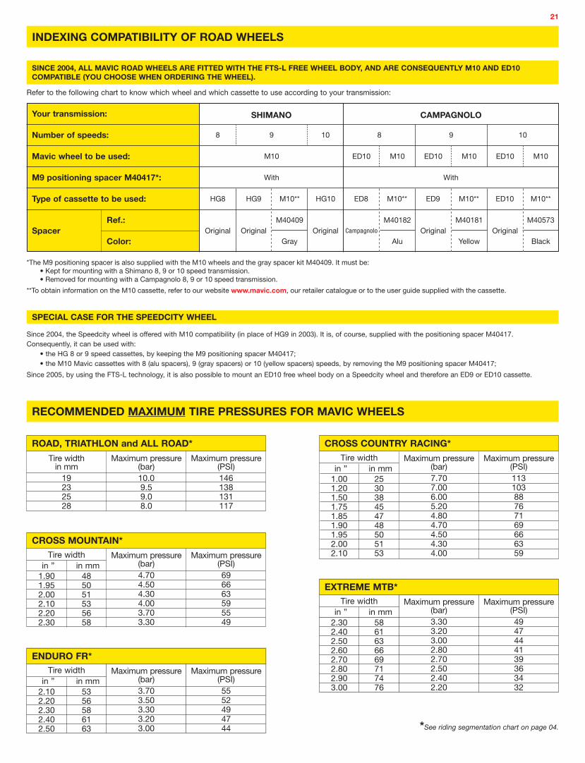
*The M9 positioning spacer is also supplied with the M10 wheels and the gray spacer kit M40409. It must be:• Kept for mounting with a Shimano 8, 9 or 10 speed transmission.• Removed for mounting with a Campagnolo 8, 9 or 10 speed transmission.
**To obtain information on the M10 cassette, refer to our website www.mavic.com, our retailer catalogue or to the user guide supplied with the cassette.
SHIMANO CAMPAGNOLO
With
ED8 M10** ED9 M10** ED10 M10**
With
M10 ED10 M10 ED10 M10 ED10 M10
Your transmission:
Number of speeds:
Mavic wheel to be used:
M9 positioning spacer M40417*:
Type of cassette to be used:
8 9 8 9 10
HG9 M10**HG8
INDEXING COMPATIBILITY OF ROAD WHEELS
SINCE 2004, ALL MAVIC ROAD WHEELS ARE FITTED WITH THE FTS-L FREE WHEEL BODY, AND ARE CONSEQUENTLY M10 AND ED10 COMPATIBLE (YOU CHOOSE WHEN ORDERING THE WHEEL).
Refer to the following chart to know which wheel and which cassette to use according to your transmission:
Since 2004, the Speedcity wheel is offered with M10 compatibility (in place of HG9 in 2003). It is, of course, supplied with the positioning spacer M40417.Consequently, it can be used with:
• the HG 8 or 9 speed cassettes, by keeping the M9 positioning spacer M40417;• the M10 Mavic cassettes with 8 (alu spacers), 9 (gray spacers) or 10 (yellow spacers) speeds, by removing the M9 positioning spacer M40417;
Since 2005, by using the FTS-L technology, it is also possible to mount an ED10 free wheel body on a Speedcity wheel and therefore an ED9 or ED10 cassette.
SPECIAL CASE FOR THE SPEEDCITY WHEEL
HG10
10
*See riding segmentation chart on page 04.
RECOMMENDED MAXIMUM TIRE PRESSURES FOR MAVIC WHEELS
5861636669717476
2.302.402.502.602.702.802.903.00
Maximum pressure (bar)3.303.203.002.802.702.502.402.20
Maximum pressure (PSI)4947444139363432
EXTREME MTB*Tire width
in ” in mm
Maximum pressure (bar)10.09.59.08.0
Maximum pressure (PSI)146138131117
ROAD, TRIATHLON and ALL ROAD*Tire width
in mm19232528
253038454748505153
1.001.201.501.751.851.901.952.002.10
Maximum pressure (bar)7.707.006.005.204.804.704.504.304.00
Maximum pressure (PSI)11310388767169666359
Tire width in ” in mm
CROSS COUNTRY RACING*
485051535658
1.901.952.002.102.202.30
Maximum pressure (bar)4.704.504.304.003.703.30
Maximum pressure (PSI)696663595549
Tire width in ” in mm
CROSS MOUNTAIN*
Campagnolo
M40182Original
Alu
M40181
Yellow
M40573
BlackSpacer
Ref.:
Color:Original Original Original
Gray
M40409Original
5356586163
2.102.202.302.402.50
Maximum pressure (bar)3.703.503.303.203.00
Maximum pressure (PSI)5552494744
ENDURO FR*Tire width
in ” in mm
22
WHEEL MAINTENANCE
REMINDER OF THE WARRANTYBefore any repair of a Mavic wheel (or any other Mavic product), please note that it has a warranty against manufacturing or material defects for a period of 2 years from the date of original purchase by the original buyer (see Mavic warranty on page 45).
This means that:
• During the warranty period, and when it is definitely covered by the warranty (first contact your MSC), you must return the Mavic wheel (or any other Mavic product) directly to your MSC, following the procedure on page 44, to benefit from the Mavic warranty.
However, if you decide to repair the wheel yourself (or any other Mavic product), your customer will lose the Mavic warranty.
• For repairs after the warranty period has expired, we advise you to refer to the following pages before carrying out work on the Mavic wheel. If replacing the rim, please note the new serial number of the rim on the original warranty card and the date of intervention.
Only this procedure will allow your customer’s new rim to be covered by the Mavic warranty.
REPAIRSThe following pages will help you to maintain the wheels in the 2008 range and are organized as follows:
HUBS ....................................................................................................................................................................................................................................... Pages 23 to 24
Replacing the front axle and bearings on the Crossmax ST 20 mm and C29ssmax 20 mm wheels .......................................................................................... Page 23
Replacing the rear axle on the R-Sys and Cosmic Carbone Ultimate wheels ............................................................................................................................. Page 23
Replacing the rear bearings on the R-Sys and Cosmic Carbone Ultimate wheels ...................................................................................................................... Page 24
WHEEL BUILDING ..................................................................................................................................................................................................................... Pages 25 to 32
Replacing a spoke or front rim on the Aksium 08, Ksyrium Equipe 08 and Crossride UB wheels .............................................................................................. Page 25
Replacing the rear rim on the Aksium 08 and Crossride UB wheels ............................................................................................................................................ Page 26
Replacing the rear rim of the Ksyrium Equipe 08 wheel ............................................................................................................................................................... Page 27
Important note for fitting Tracomp spokes ................................................................................................................................................................................... Page 28
Identifying a damaged Tracomp carbon spoke ............................................................................................................................................................................. Page 28
Removing / Refitting the Tracomp ring .......................................................................................................................................................................................... Page 29
Truing, replacing a Tracomp spoke or the front rim on the R-Sys wheel ..................................................................................................................................... Page 30
Replacing the rear rim of the R-Sys wheel .................................................................................................................................................................................... Page 31
Replacing a spoke nipple on the Cosmic Carbone Ultimate wheel.............................................................................................................................................. Page 32
Before any operation, we recommend removing:
• the wheel from the bike by releasing the quick release skewer
• the skewer, the tire
• the cassette and chain-disc (if necessary) for the rear wheel
• the brake disc (if necessary)
All maintenance operations not detailed in the following pages can be found in the 2002, 2003, 2004, 2005, 2006 or 2007 technical manuals. Refer to the product sheets (pages 5 to 20 of this manual) for more details.
All these operations can also be found at www.tech-mavic.com

23
HUBS
REPLACING THE FRONT AXLE AND BEARINGS ON THE CROSSMAX ST 20MM AND CROSSMAX 29 20MM WHEELS
Tools needed
• 1 hub wrench M40123
• Bearing press kit M40218
Refit the axle by tightening the adjustment screw as far as possible and then unscrew it 1/4 of a turn.
Use the bearing press kit M40218 to remove the old bearings and fit the new ones.
Manually keep the axle on the disc side in place and fully unscrew the adjustment nut using the hub wrench. Remove the hub axle.
Introduce end lugs of the hub wrench M40123 into the holes of the adjustment nut on the non-disc side.
Refit the wheel into the fork and check bearing play;
If there is play, gently screw the adjustment nut using hub wrench M40123 until there is no play.
REPLACING THE REAR AXLE ON THE R-SYS AND COSMIC CARBONE ULTIMATE WHEELS
Tools needed
• 2 x 5 mm Allen wrench
The cassette no longer has to be removed for this operation.
Nevertheless, it is no longer possible to remove the cassette if the free wheel body is not fitted to the hub.
Start by unscrewing the adjustment nut 1 turn using hub wrench M40123; this is to avoid damaging the bearings during refitting;
Remove the drive side axle end screw and the axle from the non-drive side.
Insert a 5 mm Allen wrench into each end of the axle and unscrew the axle end screw on the drive side.
The free wheel body is no longer held in place and is easily knocked out of position;
Replace the faulty parts, screw the axle back in and refit the axle end screw (tightening torque: 10 Nm);
Gently screw the adjustment nut using hub wrench M40123 until there is no play.
The axle end screw of all QRM+ hubs now comes with a dry thread lock on its thread. This avoids inopportune loosening of the part.
This thread lock loses its effectiveness after 4 to 5 dismantling/assembly operations. The axle end screw should then be replaced.
Axle end screws can be ordered separately to complete axle units using the following references:
Road wheels Steel M10/ED10 324 130 01 Titanium M10/ED10 995 469 01

24
REPLACING THE REAR BEARINGS ON THE R-SYS AND COSMIC CARBONE ULTIMATE WHEELS
Tools needed
• 1 bearing press kit M40120
Remove the axle (see page 23) and free wheel mechanism in accordance with the appropriate procedures for these wheels (refer to www.tech-mavic.com or previous years’ technical manuals for the procedures);
Fit the new bearings using bearing press kit M40120.
Extract the bearings using bearing press kit M40120.
Remove the axle (see page 23) and free wheel mechanism in accordance with the appropriate procedures for these wheels (refer to www.tech-mavic.com or previous years’ technical manuals for the procedures);
25
OK KO OK KO
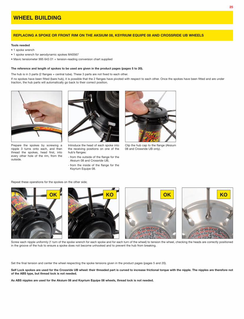
Tools needed
• 1 spoke wrench
• 1 spoke wrench for aerodynamic spokes M40567
• Mavic tensiometer 995 643 01 + tension-reading conversion chart supplied
The reference and length of spokes to be used are given in the product pages (pages 5 to 20).
The hub is in 3 parts (2 flanges + central tube). These 3 parts are not fixed to each other.
If no spokes have been fitted (bare hub), it is possible that the 2 flanges have pivoted with respect to each other. Once the spokes have been fitted and are under traction, the hub parts will automatically go back to their correct position.
Clip the hub cap to the flange (Aksium 08 and Crossride UB only).
Introduce the head of each spoke into the receiving positions on one of the hub’s flanges:
- from the outside of the flange for the Aksium 08 and Crossride UB,
- from the inside of the flange for the Ksyrium Equipe 08.
Prepare the spokes by screwing a nipple 3 turns onto each, and then thread the spokes, head first, into every other hole of the rim, from the outside.
WHEEL BUILDING
REPLACING A SPOKE OR FRONT RIM ON THE AKSIUM 08, KSYRIUM EQUIPE 08 AND CROSSRIDE UB WHEELS
Screw each nipple uniformly (1 turn of the spoke wrench for each spoke and for each turn of the wheel) to tension the wheel, checking the heads are correctly positioned in the groove of the hub to ensure a spoke does not become unhooked and to prevent the hub from breaking.
Set the final tension and center the wheel respecting the spoke tensions given in the product pages (pages 5 and 20).
Self Lock spokes are used for the Crossride UB wheel: their threaded part is curved to increase frictional torque with the nipple. The nipples are therefore not of the ABS type, but thread lock is not needed.
As ABS nipples are used for the Aksium 08 and Ksyrium Equipe 08 wheels, thread lock is not needed.
Repeat these operations for the spokes on the other side;

26
OK KO
Tools needed
• 1 spoke wrench
• 1 spoke wrench for aerodynamic spokes M40567
• Mavic tensiometer 995 643 01 + tension-reading conversion chart supplied
The reference and length of spokes to be used are given in the product pages (pages 5 to 20).
These wheels must be built as follows:
- Spokes fitted radially on the non-drive side and crossed 2 on the drive side.
- Drive side, the traction spokes must be fitted into the slots’ external slits and the non-traction spokes into the slots’ internal slits.
The hub is in 2 parts (flanges on non-drive side + tube - slots – hub nose).
If no spokes have been fitted (bare hub), it is possible that the 2 flanges pivot with respect to each other. Once the spokes have been fitted and are under traction, the hub parts will automatically go back to their correct position.
Prepare the spokes by screwing a nipple 3 turns onto each spoke;
Start on the non-drive side (shorter spokes);
With the valve hole near you, thread a spoke, head first, into the first hole to the right of the valve hole, and continue every 1 hole in 2.
Introduce the head of each spoke into the receiving positions on the hub’s flange, on the non-drive side, from the outside of the flange.
Clip the hub cap to the flange.
Turn the wheel over and introduce the remaining spokes (the longer ones) into the remaining holes in the rim.
The first spoke to the right of the valve hole is a non-traction spoke: insert it into an inside notch of the hub and repeat this 1 spoke out of 4.
The 3rd spoke to the right of the valve hole is a traction spoke: insert it into an outside notch of the hub and repeat this for all the remaining spokes.
Screw each nipple uniformly (1 turn of the spoke wrench for each spoke and for each turn of the wheel) to tension the wheel, checking the heads are correctly positioned in the groove of the hub on the non-drive side to ensure a spoke does not become unhooked and to prevent the hub from breaking.
Set the final tension and center the wheel respecting the spoke tensions given in the product pages (pages 5 to 20).
Self Lock spokes are used for the Crossride UB wheel: their threaded part is curved to increase frictional torque with the nipple. The nipples are therefore not of the ABS type, but thread lock is not needed.
As ABS nipples are used for the Aksium 08 wheel, thread lock is not needed.
REPLACING THE REAR RIM ON AKSIUM 08 AND CROSSRIDE UB WHEELS

27
OK KO
Tools needed
• 1 spoke wrench
• 1 spoke wrench for aerodynamic spokes M40567
• Mavic tensiometer 995 643 01 + tension-reading conversion chart supplied
The reference and length of spokes to be used are given in the product pages (page 6).
These wheels must be built as follows:
- Spokes fitted radially on the drive side and crossed 2 on the non-drive side.
- On the non-drive side, spokes hot crossed and laced (going from the hub to the rim, the traction spokes pass above and then below the non-traction spokes).
Prepare the spokes by screwing a nipple 3 turns onto each spoke;
Start with drive side spokes (shorter spokes);
With the valve hole near you, thread a spoke, head first, into the first hole to the left of the valve hole, and continue every 1 hole in 2.
Insert the spoke heads into the hub notches on the drive side, from the inside.
The first spoke to the left of the valve hole must be located into a notch for which there is no slot opposite it on the non-drive side.
Now thread a spoke, head first, into the 3rd hole to the right of the valve hole, and then continue 1 hole in 4;
And finally, thread a spoke, head first, into the first hole to the right of the valve hole. These are traction spokes.
Present the head of this spoke under the 1st crossed non-traction spoke, and then above the 2nd crossed non-traction spoke. Place the head of this spoke into the notch of the corresponding slot.
Repeat the last operation for all the remaining spokes;
Screw each nipple uniformly (1 turn of the spoke wrench for each spoke and for each turn of the wheel) to tension the wheel, checking the heads are correctly positioned in the groove of the hub on the drive side to ensure a spoke does not become unhooked and to prevent the hub from breaking.
Set the final tension and center the wheel respecting the spoke tensions given in the product pages (pages 5 to 20).
As ABS nipples are used, thread lock is not needed.
REPLACING THE REAR RIM OF THE KSYRIUM EQUIPE 08 WHEEL
Insert the heads of these spokes into the hub’s inside slots. These are non-traction spokes.

28
With the R-Sys Tracomp concept, the nipple and the tubular spoke are fixed together. Thus, when turning the nipple of a tubular spoke, the spoke itself turns along its entire length (nipple, tube and head).
In the Tracomp concept, the heads of the tubular spokes are held fixed inside the hub body by the Tracomp ring in order to withstand the compression. This prevents the spokes from turning freely.
CONSEQUENTLY, BEFORE TURNING THE NIPPLE OF A TUBULAR SPOKE (TRUING, REPLACING A SPOKE, REPLACING A RIM), THE TRACOMP RING MUST FIRST BE REMOVED FROM THE HUB.
Press the carbon Tracomp spoke with your fingers along its entire length.
Carry out rotational movements around the carbon Tracomp spoke, along its entire length, using your fingers.
If a cracking can be heard or if the spoke feels elastic when rotated, then the spoke is broken and must be replaced.
When a spoke is broken, it is impossible to center or laterally and radially true the wheel because the head of the spoke does not turn at the same time as the nipple.
IMPORTANT NOTE FOR FITTING TRACOMP SPOKES
Tools needed
• Safety gloves
Because of their unidirectional carbon construction, and particularly after a shock, the carbon Tracomp spokes may split: if this happens, they are no longer able to support compression forces, but they continue to support the traction forces associated with spoke tension.
In this case, the wheel does not go out of true and the shape of the spoke stays the same, making it difficult to detect a damaged spoke.
To identify a damaged spoke, proceed as follows:
IDENTIFYING A DAMAGED CARBON TRACOMP SPOKE

29
OK KO
Place the Tracomp ring tool 996 080 01 onto the hub in such a way the picture of the screwdriver is visible.
Pass the tip of the screwdriver through the hole in the Tracomp ring tool.
The spokes are now able to turn freely and can be extracted.
Refitting the Tracomp ring:
REMOVING / REFITTING THE TRACOMP RING
Tools needed
• Tracomp ring tool 996 080 01
• 1 x 4/5 mm flat screwdriver
• A mallet
• 1 x 5 mm Allen wrench and 1 x hub wrench M40123 (front wheel) or 2 x 5 mm Allen wrenches (rear wheel)
Removing the Tracomp ring:
Remove the axle in accordance with the procedure for the hub in question (refer to www.tech-mavic.com or previous years’ technical manuals).
Insert the tip of the screwdriver through the slot in the Tracomp ring tool and into the groove of the Tracomp ring.
Push the screwdriver handle downwards to lever out the Tracomp ring.
Present the Tracomp ring to the spoke heads with the conical side downwards and the inside groove facing upwards.
Place the Tracomp ring tool 996 080 01 against the ring in such a way the picture of the mallet is visible.
Refit the axle in accordance with the procedure for the hub in question (refer to www.tech-mavic.com or previous years’ technical manuals).
Forcefully fit the Tracomp ring into the hub using a mallet. The entire surface of the bottom side of the Tracomp ring must be in contact with the hub body.

30
OK KO
Once the Tracomp ring has been removed, fully unscrew the nipple and slide the spoke along the hole in the hub to remove it. Refit the new spoke in the same way.
Screw the nipples into the rim using spoke wrench 996 079 01 until the thread lock has disappeared.
TRUING, REPLACING A TRACOMP SPOKE OR THE FRONT RIM ON THE R-SYS WHEEL
Tools needed
• Tracomp spoke wrench 996 079 01
• Tracomp ring tool 996 080 01
• A flat screwdriver
• A mallet
• 1 x 5 mm Allen wrench and 1 x hub wrench M40123 (front wheel) or 2 x 5 mm Allen wrenches (rear wheel)
•
Remove the Tracomp ring in accordance with the appropriate procedure (see page 29 or consult the www.tech-mavic.com website);
Without refitting the Tracomp ring, replace the axle so as to be able to place the wheel in the centering unit.
Set the final tension and center the wheel taking care to respect appropriate spoke tensions;
Remove the axle once again in order to refit the Tracomp ring in accordance with the appropriate procedure (see page 29 or consult the www.tech-mavic.com website);
Refit the axle in accordance with the appropriate procedure (see page 23 or consult the www.tech-mavic.com website);
If you have to replace the spoke with the integrated magnet, you should first of all unclip the plastic clips that hold the magnet in place in order to thread the spoke through the hole in the hub.

31
OK KO
Screw the nipple of a Zicral spoke 2 turns into the 1st hole to the right of the valve hole, then do the same for all the Zicral spokes, 1 hole in 2 of the rim.
As the holes in the rim are orientated, the spokes are naturally positioned in the right direction. non-traction spokes must pass below the traction spokes, without touching at the crossover point.
REPLACING THE REAR RIM OF THE R-SYS WHEEL
Tools needed
• Tracomp spoke wrench 996 079 01
• Tracomp ring tool 996 080 01
• A flat screwdriver
• A mallet
• 2 x 5 mm Allen wrenches
•
The reference and length of spokes to be used are given in the product pages (pages 9 and 10).
These wheels must be built as follows:
- Spokes fitted radially on the non-drive side and crossed 2 on the drive side.
- On the drive side, the traction spokes locate into the notches of the outermost slots of the hub.
Remove the axle and Tracomp ring in accordance with the appropriate procedures (see page 29 or consult the www.tech-mavic.com website);
With the valve hole near you, place the rim such that the 2 raised indicator bumps are to the right of the valve hole;
Start with the drive side;
Insert the heads of these spokes into the hub slots: the heads of the non-traction spokes should be inserted into the inside slits of the slots, the heads of the traction spokes into the outside slits.
Remove the axle once again in order to refit the Tracomp ring in accordance with the appropriate procedure (see page 29 or consult the www.tech-mavic.com website).
Turn the wheel over and insert all the Tracomp spokes, nipple first, into the hub on the non-drive side.
Tighten the nipples of the Tracomp spokes into the remaining rim holes until the thread lock disappears.
Without refitting the Tracomp ring, replace the axle so as to be able to place the wheel in the centering unit. Set the final tension and center the wheel taking care to respect appropriate spoke tensions.

32
Turn the wheel on the drive side and remove the clip that holds the spokes in place using a small flat screwdriver.
Fully unscrew the nipple to be replaced and remove it via the inside of the hub.
REPLACING A SPOKE NIPPLE ON THE COSMIC CARBONE ULTIMATE WHEEL
Tools needed
• 1 traditional spoke wrench
• 1 small flat screwdriver
• Mavic tensiometer 995 643 01 + tension-reading conversion chart supplied
Screw the new nipple 2 turns onto the threaded rod and insert the nipple head into its correct position.
Replace the clip that holds the spokes in place and set the final tension and center the wheel taking care to respect appropriate spoke tensions.

33
MAVIC® RIMS
SEGMENTATION OF THE RIM RANGE
ROAD & TRIATHLON
AERODYNAMIC CLASSIC ALL ROAD
REFLEX (tubular)
A 719
A 319
A 317 DISC*
CROSS COUNTRY
CROSS MOUNTAIN EXTREME MTB
XC 717 DISC
XM 819 DISC (UST)
EX 823 DISC (UST)
EX 729 DISC
EX 721
XM 819 (UST)
XM 719 DISC
XM 517*
EN 321 DISCXM 317 DISC*
XM 317
XM 117 DISC*
MTB
XM 117*
A 119*
* O.E.M. specific rims
XC 717
EX 325 DISC
OPEN PRO
OPEN SPORTCXP22
CXP33
CXP23*
ENDURO FR
XM 719
EN 521 DISCNEW
TN 719 DISCNEW

34
CONDITIONS OF USE FOR A RIM
CONDITIONS OF USE TO BE GIVEN TO YOUR CUSTOMERS
Mavic uses the most advanced technology in the design of its rims and wheels. However, a rim cannot last forever and wears down according to its use: type of riding, terrain, brake pad, spoke tension, tires, tire pressure, weather conditions, etc.
Each rim has been designed for a specific use and discipline (Road, Cross-Country, Freeride, Downhill, Touring…). Any other use of a rim for which it has not been designed is highly inadvisable, the sole responsibility of the user and voids the Mavic warranty.
Please advise your customers of the following points:
• Choose a suitable rim designed for the type of riding you wish to do: do not use a road rim on an MTB, do not use Cross Country rims to build wheels for a bike to be used for freeride, downhill...
• You must follow the instructions in this technical manual for tire pressure and sizes (see following charts);
• Respect the appropriate spoke tensions; Mavic recommends spoke tensions between 70 and 90 kg (for a front or rear wheel on the free wheel side with a crossed 3 pattern). Inappropriate spoke tension can generate too much stress and damage the rim;
• Clean the rims regularly using the Mavic soft stone (M40410);
• Remove stones and metal particles from the brake pads;
• Replace the brake pads when they are worn;
• Do not use a rim if the braking surfaces are worn, if eyelets are missing, or in any other case where safety might be compromised. The rim is a part that wears out as do brake pads, and must be replaced if it is worn (sidewall hollowed by wear, or cut out, cracked rim…);
• For rims fitted with a wear indicator (internal or external) do not continue to use the rim if the indicator appears (internal wear indicator) or disappears (external wear indicator) on at least one of the 2 braking surfaces;
• For rims not fitted with a wear indicator, use a depth gauge to check that the maximum wear on each side is not more than 0.4 mm;
• Check or have your rims checked regularly, at least at the start of each season and if possible after intensive use or if you have a doubt about spoke tension or the type of tire used. When checking, look inside (especially under the rim tape) and outside the rim. Check for signs of fatigue or wear: damage to braking surfaces, appearance or disappearance of the wear indicator (only on rims fitted with a wear indicator), cracks in the sidewalls or around the eyelets…
• The total weight of the rider and his/her equipment (not including the bike) must not exceed the following values:
- Road rims: 100 kg;
- All Road rims: 105 kg for A 119, A 319 and A 317 Disc rims, 125 kg for the A 719 rim.
- MTB rims: 90 kg for XM 117, XM 117 Disc, XM 317, XM 317 Disc, XM 517, XC 717 and XC 717 Disc rims; 115 kg for XM 719, XM 719 Disc, TN 719 Disc, XM 819, XM 819 Disc, EN 521 Disc, EN 321 Disc, EX 325 Disc, EX 721, EX 729 Disc and EX 823 Disc rims.
Following these recommendations will guarantee longer product life for the rims, maximum performance and riding enjoyment.
GENERAL POINTS

35
TECHNICAL FEATURES OF THE NEW 2008 RIMS
Mavic rims not appearing in the above chart have not been changed. Their technical features can be found in the technical manuals from previous years or on the technical manual website: www.tech-mavic.com
MTB
* See riding segmentation chart on page 33.
485051535658
1.901.952.002.102.202.30
Maximum pressure
(bar)4.704.504.304.003.703.30
Maximum pressure
(PSI)696663595549
CROSS MOUNTAIN*Tire
width in ” in mm
5861636669717476
2.302.402.502.602.702.802.903.00
Maximum pressure
(bar)3.303.203.002.802.702.502.402.20
Maximum pressure
(PSI)4947444139363432
EXTREME MTB*Tire
width in ” in mm
Maximum pressure
(bar)7.007.007.006.006.005.605.204.804.50
Maximum pressure
(PSI)103103103888882767166
ALL ROAD*Tire
width in mm
283032353740444750
Maximum pressure
(bar)10.09.59.08.0
Maximum pressure
(PSI)146138131117
ROAD & TRIATHLON*Tire
width in mm
19232528
RECOMMENDATION FOR MAXIMUM TIRE PRESSURE
253038454748505153
1.001.201.501.751.851.901.952.002.10
Maximum pressure
(bar)7.707.006.005.204.804.704.504.304.00
Maximum pressure
(PSI)11310388767169666359
CROSS COUNTRY RACING*Tire
width in ” in mm
5356586163
2.102.202.302.402.50
Maximum pressure
(bar)3.703.503.303.203.00
Maximum pressure
(PSI)5552494744
ENDURO FR*Tire
width in ” in mm
CROSS MOUNTAIN ENDURO FR
TN 719 DISC EN 521 DISC
RIM WIDTH
Concept
Material MAXTAL 6106
Valve hole diameter (in mm) 8.5, supplied with valve adapter 8.5, supplied with valve adapter
ETRTO compatibility 622 x 19C 559 x 21C
Recommended tire width (in mm) 1.5 à 2.3 2.1 à 2.5
Eyelets Single Single
Average weight (in grams) 510 540
Finish and drilling Black 32-hole 995 921 32 995 681 32
Black 36-hole 995 921 36 995 681 36
Recommended spoke nipple length (in mm) 12 12
Spoke support diameter (in mm) 598 532
Recommended rim tape (ETRTO x length x thickness) 622 x 20 x 0,6 559 x 23 x 0,6

36
SYSTEMS
COMPUTERS
WINTECH ALTI
WINTECH HR
WINTECH ES
WINTECH E-BOLT
WINTECH FS
ELECTRONICACCESSORIES
PEDALING CADENCE KIT
HOME TRAINER SENSOR KIT
2ND BIKE KIT
HANDLEBAR SUPPORT KIT
BRAKES
SSC BRAKES
TRANSMISSION
M10 CASSETTE NO.1
M10 CASSETTE NO.2
M10 CASSETTE NO.3
M10 CASSETTE NO.4
WHEEL ACCESSORIES
QUICK RELEASE SKEWER BR 601
QUICK RELEASE SKEWER BX 601
SAINT DERAILLEUR AXLE KIT
QUICK RELEASE AXLE KIT
9 AND 20 MM FORK SUPPORT NUT KITS
9 AND 12 MM FRAME SUPPORT NUT KITS
TRACK COG LOCK RING
KITS
REPLACEMENT KIT
ROAD SPOKE KIT
MTB SPOKE KIT
ACCESSORIES
ROAD WHEEL BAG
MTB WHEEL BAG
SOFT STONE
UNIVERSAL MAGNET
ELECTRONIC MECHANIC MISCELLANEOUS
NEW
NEW

37
Dear dealers, we would like to remind you that it is your responsibility to give the following to your customers:
- product instructions- warranty card (that you have filled out)- all the accessories supplied with the product.
We also advise the users of Mavic components to follow the instructions below:
• Follow the conditions of use described at the top of each Mavic component product page. Any other use outside of these conditions is inadvisable, the sole responsibility of the user and voids the Mavic warranty;
• Although water resistant, it is strongly inadvisable to use pressurized water on electronic and mechanical components;
• It is also inadvisable to use solvents and petroleum products to clean the various components. It is preferable to use warm water, or soap and water, and to dry with a cloth.
• Do not leave the liquid crystal WINTECH screens exposed to the sun (e.g. behind the windshield of your vehicle);
• Each of Wintech’s electronic components has its own digital code. The synchronisation operation allows components of the same system to function with the same digital code and therefore be impenetrable to outside signals. This means that each component of a system cannot be used with the components of another system fitted to another bike ( technology).
This synchronization operation is vital for the correct operation of the system. It must be carried out before using the system for the first time and each time one of the batteries is replaced.
Following these recommendations will guarantee longer product life for the components, maximum performance and riding enjoyment.
GENERAL POINTS
MAINTENANCE
• Replacing the batteries: only use the following battery types:
- CR2032: HR, ES, FS and E-Bolt computers and speed and cadence sensors.
- CR2430: Alti computer
• Battery life: 12 to 24 months (depending on use).
• Although resistant to solvents and petroleum products, it is inadvisable to use these types of products to clean the various components.
• Recommendation: use warm water, or soap and water, and dry with a cloth.
• Do not leave the computer in the sun (e.g. behind the winshield of a vehicle) when not in use.
• Do not dismantle any component; this will make the warranty void.
• Biking is a sport which may require intense physical activity and as such poses a risk dependent on the route and the environment. For your own safety, keep an eye on the road and the traffic. Wear a helmet.
• The features, shape and general presentation are subject to change without prior notification.
DISPOSING OF WORN EQUIPMENT BY PRIVATE USERS IN THE EUROPEAN UNION:
If this symbol is on the product or its packaging, it means you cannot dispose of the product as you do ordinary household waste.
On the contrary, you are responsible for disposing of worn equipment, and are required to take it to an approved electrical and electronic equipment recycling point.
Separate sorting and recycling of your worn equipment preserves natural resources and ensures the equipment is recycled in such a way as to respect human health and the environment.
For further information on suitable waste disposal points, please contact your town hall, your household waste collection service or the shop where you purchased the product.
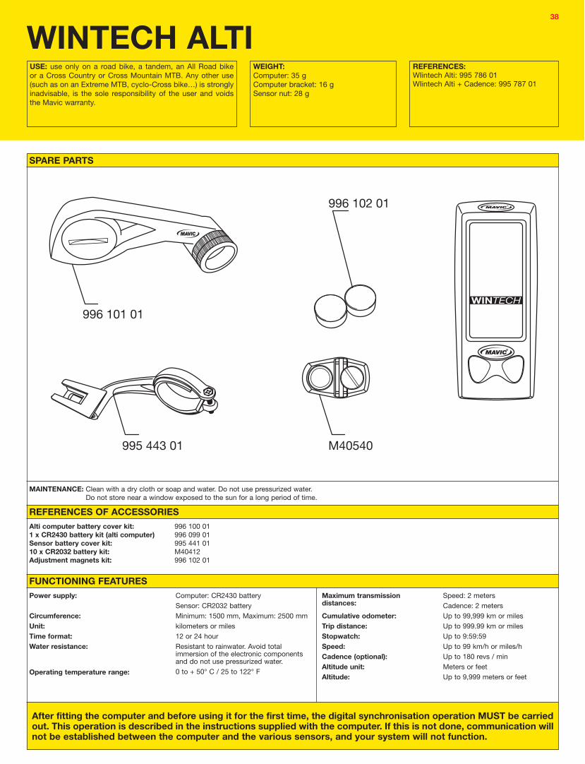
38
996 102 01
996 101 01
995 443 01 M40540
SPARE PARTS
WINTECH ALTI
After fitting the computer and before using it for the first time, the digital synchronisation operation MUST be carried out. This operation is described in the instructions supplied with the computer. If this is not done, communication will not be established between the computer and the various sensors, and your system will not function.
FUNCTIONING FEATURESPower supply:
Circumference:Unit:Time format: Water resistance:
Operating temperature range:
Computer: CR2430 batterySensor: CR2032 batteryMinimum: 1500 mm, Maximum: 2500 mmkilometers or miles12 or 24 hourResistant to rainwater. Avoid total immersion of the electronic components and do not use pressurized water. 0 to + 50° C / 25 to 122° F
USE: use only on a road bike, a tandem, an All Road bike or a Cross Country or Cross Mountain MTB. Any other use (such as on an Extreme MTB, cyclo-Cross bike…) is strongly inadvisable, is the sole responsibility of the user and voids the Mavic warranty.
WEIGHT:Computer: 35 gComputer bracket: 16 gSensor nut: 28 g
REFERENCES:WIintech Alti: 995 786 01WIintech Alti + Cadence: 995 787 01
MAINTENANCE: Clean with a dry cloth or soap and water. Do not use pressurized water.Do not store near a window exposed to the sun for a long period of time.
REFERENCES OF ACCESSORIESAlti computer battery cover kit:1 x CR2430 battery kit (alti computer)Sensor battery cover kit:10 x CR2032 battery kit:Adjustment magnets kit:
996 100 01996 099 01995 441 01M40412996 102 01
Maximum transmission distances:
Cumulative odometer: Trip distance:Stopwatch:Speed:Cadence (optional):Altitude unit: Altitude:
Speed: 2 metersCadence: 2 metersUp to 99,999 km or milesUp to 999.99 km or milesUp to 9:59:59Up to 99 km/h or miles/hUp to 180 revs / minMeters or feetUp to 9,999 meters or feet

39
996 102 01
996 101 01
995 443 01 M40540
SPARE PARTS
WINTECH E-BOLT
After fitting the computer and before using it for the first time, the digital synchronisation operation MUST be carried out. This operation is described in the instructions supplied with the computer. If this is not done, communication will not be established between the computer and the various sensors, and your system will not function.
FUNCTIONING FEATURESPower supply:Circumference:Unit:Time format: Water resistance:
Operating temperature range:
CR2032 battery (computer)Minimum: 1500 mm, Maximum: 2500 mmkilometers or miles12 or 24 hourResistant to rainwater. Avoid total immersion of the electronic components and do not use pressurized water.0 to + 50° C / 25 to 122° F
USE: use only on a road bike, a tandem, an All Road bike or a Cross Country or Cross Mountain MTB. Any other use (such as on an Extreme MTB, cyclo-Cross bike…) is strongly inadvisable, is the sole responsibility of the user and voids the Mavic warranty.
WEIGHT:Computer: 32 gComputer bracket: 16 gSkewer sensor: 28 g
REFERENCES:Wintech E-Bolt: 995 794 01Wintech E-Bolt + Cadence: 995 793 01
MAINTENANCE: Clean with a dry cloth or soap and water. Do not use pressurized water.Do not store near a window exposed to the sun for a long period of time.
REFERENCES OF ACCESSORIESSensor + computer battery cover kit:Chest strap battery cover kit:10 x CR2032 battery kit:Adjustment magnets kit:
995 441 01995 442 01M40412996 102 01
Maximum transmission distances:
Cumulative odometer: Trip distance:Stopwatch:Speed:Cadence (optional):Heart rate:
Speed: 2 metersCadence: 2 metersHeart rate monitor: 2 metersUp to 99,999 km or milesUp to 999.99 km or milesUp to 9:59:59Up to 99 km/h or miles/hUp to 180 revs / minUp to 240 beats / min

40
This information is in addition to that given for the Wintech ES, HR and E-Bolt.
Incorrect altitude display:
1- The computer uses atmospheric pressure to calculate altitude.
2- The start altitude must therefore be calibrated against a known value.
3- If in doubt, check the battery and replace it if it is less than 3 Volts.
Incorrect cumulative altitude display:
1- The computer uses atmospheric pressure to calculate cumulative altitude.
2- Abrupt changes in atmospheric conditions may therefore lead to errors in the calculated cumulative altitude.
3- If in doubt, check the battery and replace it if it is less than 3 Volts.
Continually fluctuating altitude reading, even when at standstill:
1- The computer uses atmospheric pressure to calculate altitude.
2- The altitude displayed at a given place may vary if the atmospheric conditions change.
3- If in doubt, check the battery and replace it if it is less than 3 Volts.
If the problem continues after having carried out all the above checks, contact your Mavic Service Center (MSC).
SPECIFIC WINTECH ALTI TROUBLESHOOTING
The batteries lose part of their capacity in the cold. Incorrect functioning may occur during an early morning ride if the battery is at 80% of its capacity, but become normal again when the temperature increases.
All memorized information is lost each time the battery is removed; remember to note the information before removing the battery and to carry out the synchronisation operation again once the battery has been replaced.

41
D
F
A
CA
B
D
A
B
C
D
C
A
B
REFERENCE NAME
323 477 01 Multifunction tool: Removing the UST Tubeless rim tape (A), Fitting the UST rim tape (C) Adjusting the front axles on the Cosmos, Ksyrium Equipe, Crossland, Crossmax Enduro, Crossmax Enduro Disc, Cosmic Elite 05 and Speedcity 05 (B), Aksium, Crossride 06, Crossride Disc, Crosstrail, Crosstrail Disc, Aksium 08, Ksyrium Equipe 08, Crossride UB/Disc 08, Crossride UB wheels
M40119 Bearing press kit for bearings: M40075 M40076
M40120 Bearing press kit for bearings: M40077 M40078
M40631 Bearing press kit for bearings: M40632
M40373 Guide ring and bearing press kit for bearings: M40318 M40660
M40218 Bearing press kit for bearings: M40179
323 945 01 Bearing press kit for bearings: M4077
324 300 01 Bearing press kit for bearings: 324 170 01
M40410 Mavic soft stone for cleaning the braking surface of the rim, Ceramic or UB Control.
TOOLSCUSTOMER SERVICE
PRODUCT
A+B: Bearing press kit for the front wheel.A+C: Bearing press kit for the rear wheel.D: Bearing press kit for the front and rear wheels.E: Bearing press kit for the front and rear wheels.F: Guide ring for the 12 mm Allen wrench needed for removing the free wheel on the Crossroc UST, Crossroc UST Disc, Crossride, Crossride Ceramic, Cosmos and
Cosmic Elite wheels.
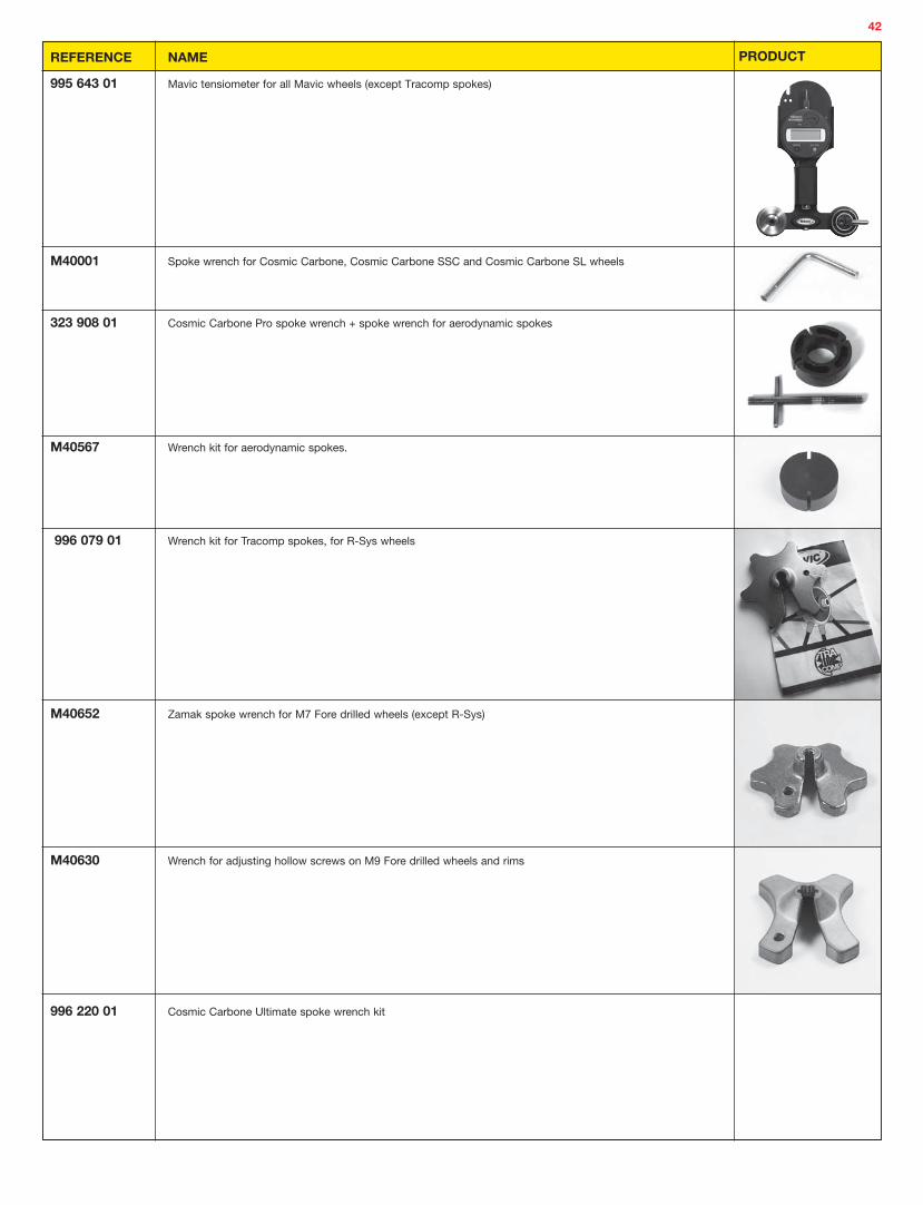
42
REFERENCE NAME
995 643 01 Mavic tensiometer for all Mavic wheels (except Tracomp spokes)
M40001 Spoke wrench for Cosmic Carbone, Cosmic Carbone SSC and Cosmic Carbone SL wheels
323 908 01 Cosmic Carbone Pro spoke wrench + spoke wrench for aerodynamic spokes
M40567 Wrench kit for aerodynamic spokes.
996 079 01 Wrench kit for Tracomp spokes, for R-Sys wheels
M40652 Zamak spoke wrench for M7 Fore drilled wheels (except R-Sys)
M40630 Wrench for adjusting hollow screws on M9 Fore drilled wheels and rims
996 220 01 Cosmic Carbone Ultimate spoke wrench kit
PRODUCT

43
REFERENCE NAME
M40123 Hub wrench for adjusting free play on Mavic QRM+ hubs
996 204 01 Mavic thread lock
996 136 01 Mavic mineral oil for lubricating the FTS, FTS-L, FTS-X and ITS4 free wheel bodies.Capacity 60 ml.Only use this oil for lubricating FTS, FTS-L, FTS-X and ITS4 free wheel bodies
996 080 01 TraComp ring tool
PRODUCT

44
GENERAL PROCEDURE FOR ALL SERVICE SUPPORT REQUESTS
1. Contact the Mavic Service Center in your geographical zone to obtain a PRODUCT RETURN NUMBER;
2. In accordance with the instructions of your Mavic Service Center, send the damaged part or product to them with a note containing the following information:
• Your name and address;
• The product return number that was given to you. This number should also be indicated on the outside of your package;
• The reason for the return;
• Proof of date of purchase attesting that the product was sold within the last 2 years (receipt or warranty card filled out).
WARNING: the wheels must be sent without the tire, cassette, skewer, bag or anything else in order to avoid any risk of loss or damage. To be able to process your request as quickly as possible, we ask you to follow this procedure. ANY OTHER TYPE OF RETURN WILL BE REFUSED.
3. After the Mavic Service Center receives your package, it will make a diagnosis and will declare whether the damaged product is covered by the warranty or not. The product will then be exchanged or repaired.
NOTE: If the warranty is refused, your Mavic Service Center will inform you about the cost of the repair.
If the product cannot be repaired, it will be destroyed by Mavic unless you have given prior contrary instructions.
If you decide to repair the Mavic product, please read the preceding pages.
Your Mavic Service Center is available for information regarding repairs and the Mavic warranty. Please do not hesitate to contact them.
REPLACEMENT BY THE SAME PRODUCT OR BY A SIMILAR PRODUCT
IN THE CURRENT LINE
REPLACEMENT OF THE DEFECTIVE PARTS, GLOBAL CONTROL OF THE PRODUCT
NON-REPAIRABLEPRODUCTSREPAIRABLE PRODUCTS
INFORMATION BY THE MSC
WARRANTY REFUSAL WARRANTY ACCEPTANCE
RECEIVING PRODUCT / MSC DIAGNOSIS
CONTACT YOUR MAVIC SERVICE CENTER TO
OBTAIN A PRODUCT RETURN NUMBER
RETURN
WARRANTY
CUSTOMER
REPAIR
INVOICE
RETAILER

45
MAVIC WARRANTYMavic products purchased from a Mavic authorized dealer are guaranteed against manufacturing and material defects for a period of 2 years from the date of original purchase, under the following conditions.
OBLIGATIONSMavic will replace or repair a product or a part considered to be defective by Mavic. This is Mavic’s only liability.
Complementary warranties may exist according to regional laws. In France, Mavic guarantees against hidden defects as required by French law, within the conditions and limits laid down by articles 1641 and the Civil Code.
RESTRICTIONSThis warranty does not cover the consequences of normal wear & tear, damage resulting from shipping, storage, accidents, negligence, shocks or falls, failure to follow instructions for use, improper installation or installation with incompatible products, poor maintenance, normal wear & tear, abnormal or improper use, modification or alteration of the product.
The conditions of the Mavic warranty do not apply to products purchased from dealers other than Mavic authorized dealers, including the conformity of products warranty.
This warranty is not transferable and only applies to the original purchaser.
This warranty does not cover the consequences of normal wear & tear of parts that can wear out such as the braking surfaces of rims (for rim braking systems), brake pads, bearings, pawl assemblies, seals, rear derailleur jockey wheels, batteries, etc.
This warranty does not cover products whose repair has not been carried out by the Mavic Service Center or its representative in the country concerned (1).
This warranty does not cover any product whose item number or identification has deteriorated or been removed.
This warranty does not apply to «Mavic Special Race Service» products (2).
This warranty does not exclude the specific rights in each country. A consumer may have other rights depending on his/her place of residence. Certain jurisdictions do not allow for the exclusion or limitation of specific damages, secondary or as a result of, or limitations on the duration of the warranty. Therefore, these exclusions and limitations do not apply to everyone. Local taxes, customs duty or shipping fees may be applied. In the United States, additional rights that are different from one state to another may also be applied. If one part of this warranty was found to be inapplicable by an administrative or judicial procedure, the other parts would remain applicable.
APPLICATION PROCEDUREMavic authorized dealers are responsible for managing all claims under the warranty. The authorized dealer must obtain authorization from the Mavic Customer Service (or its representative in certain countries (1)) prior to the return of the defective product (3).
The complete product with proof and date of purchase (sales receipt, copy of the warranty card…) has to be sent by the authorized dealer to the Mavic Service Center (or its representative in certain countries (1)), who will ensure proper procedures are followed.
The new or repaired product will be returned to the authorized dealer.
WARRANTY CARDThe warranty card that is printed in the user guide delivered with each product must be dated, signed and stamped by the authorized dealer, and saved by the customer with no limitation in the duration. It must be used in any claims.
(1) Updated lists are available upon request to: Mavic - 74996 Annecy Cedex 09 or on the Mavic website: www.mavic.com(2) Products engraved «SSC» or whose serial number has been used by the Mavic Race Department.(3) Any claims made by any other means or without prior agreement for the return cannot be taken into account.
MAVIC WARRANTY AND CUSTOMER SERVICE
CONTACTING YOUR MAVIC SERVICE CENTER
COUNTRY
MSC GERMANY
MSC AUSTRALIA
MSC AUSTRIA
MSC BENELUX
MSC CANADA EAST
MSC CANADA WEST
MSC SPAIN AND PORTUGAL
MSC FRANCE
MSC UK
MSC ITALY
MSC JAPAN
MSC NEW ZEALAND
MSC POLAND
MSC CZECH REPUBLIC
MSC SWITZERLAND
MSC USA
TELEPHONE
(+49) 08033 305163
(+61) 3 8878 1000
(+49) 08033 305163
(+32) 01 434 7470
(+1-514) 332 1320 or 1-800 363 0693
(+1-604) 324 6900 or 1-800 363 0693
(+34) 93 729 24 74
(+33) 04 50 65 72 81
(+44) 1256 408 637
(+39) 03 5499 3975
(+81) 04 8997 4501
(+64) 4 528 3608
(+48) 071 324 69 68
(+420) 566 624 336
(+41) 041 784 12 78
(+1-888) 466 28 42
FAX
(+49) 08033 305169
(+61) 3 8878 1001
(+49) 08033 305169
(+32) 01 432 3904
(+1-514) 335 1691
(+1-604) 324 6100
(+34) 93 729 04 93
(+33) 04 50 65 71 45
(+44) 1256 465 562
(+39) 03 5499 3912
(+81) 04 8997 2701
(+64) 4 528 3601
(+48) 071 327 80 92
(+420) 566 626 240
(+41) 041 784 12 73
(+1-978) 373 1113

more atwww.mavic.com
Salomon S.A.Mavic®
Metz Tessy74996 Annecy Cedex 9Tel: (+33) 04 50 65 71 71Fax: (+33) 04 50 65 71 96
Printed in France 07/2007 © SALOMON S.A. Limited Liability Company with a Board of Directors and a capital of: 23 509 981.50 €.Head office: lieu-dit “La Ravoire” Metz-Tessy (74). RCS Annecy 325 820 751 00106 - A.P.E. 364 Z. Intra-community VAT no. FR 55 325 820 751.Head office fax: 33 (0)4 50 65 71 96. Postal address and telephone no. for all sites: Salomon S.A. - Mavic 74996 Annecy Cedex 9 - France. Tel. 33 (0)4 50 65 71 71.This document is not legally binding. SALOMON S.A. reserves the right not to sell all products in certain countries and to effect any useful or necessary changes. All rights reserved. Reproduction prohibited. Indicated wheel weights +/- 5 %, without rim tape, quick release skewer or valve for the Tubeless wheels on the industrial pre-series models. Rim weight +/- 10 %. MAVIC® is a deposited brand of SALOMON S.A.Please read carefully the recommendations for rim use in this documentPhotos: Didier Brandelet.Graphic design: www.ericleprince.com / Realization: Didier Brandelet-Blue / Printer: Imprimerie F rreol.
AustraliaGroupe SportifPty Ltd27 Ceylon Street,Nunawading 3131 VictoriaTel: (+61) 3 8878 1000Fax: (+61) 3 8878 1001
AustriaMavic®-Vertretung Geigelsteinstrasse 10 D-83080 Oberaudorf Tel: (+43) 0463 298 144Fax: (+43) 0463 298 146
BeneluxCodagexZandbergen 10 2480 Dessael BelgiumTel: (+32) 014 34 74 74Fax: (+32) 014 32 39 04
CanadaOutdoor Gear Dist.2708 Diab -Ville St Laurent,QC HS4 1E8Tel: (+1-514) 332 1320Fax: (+1-514) 335 1691
ChinaHolyBrother Commercial Co., Ltd.Stand 13-14 Workers’ StadiumNorth Road Workers’ StadiumChaoyang District, 100027 BeijingTel: (+86) 10 6551 5770 ext. 12Fax: (+86) 10 6551 2052
Czech RepublicKastarBrodska 10CZ 591 01 Zdar n/SazavouTel: (+420) 566 624 336Fax: (+420) 566 626 240
FranceSalomon s.a.Mavic®
Metz Tessy74996 Annecy Cedex 9Tel: (+33) 04 50 65 71 71Fax: (+33) 04 50 65 71 96
GermanyMavic®-Vertretung Geigelsteinstrasse 10 D-83080 Oberaudorf Tel: (+49) 08033 305 200Fax: (+49) 08033 305 299
ItalyVittoriaVia Papa Giovanni XXIII, 124040 Madone (BG)Tel: (+39) 035 499 39 11Fax: (+39) 035 499 39 12
JapanMavic®
2-5-7 Ariake, Koto-ku Tokyo 135-0063Tel: +81 (0)3 3527 8718Fax: +81 (0)3 3527 8738
New ZealandCycles Etc151 Neilson StreetOnehunga - AucklandTel: (+64) 4 528 3608Fax: (+64) 4 528 3601
PolandHarfa-Harrysonul. Robotnicza 52a53-608 WroclawTel: (+48) 071 372 15 70Fax: (+48) 071 327 80 92
Spain / PortugalSalomon s.a.Mavic®
Ctra. de Rubi 72-74Edificio Horizon 3°08190 Sant Cugat Del VallesBarcelonaTel: (+34) 93 544 10 48Fax: (+34) 93 583 00 99
SwitzerlandMavic®-Vertretung Geigelsteinstrasse 10 D-83080 Oberaudorf Tel: (+41) 041 784 12 74Fax: (+41) 041 784 12 75
U.S.A.Mavic® Inc17 Parkridge RoadHaverhill, MA 01835Tel: (+1-888) 466 2842Fax: (+1-978) 373 1113