Embed Size (px)
Citation preview

(English) DM-RD0003-08
Dealer's Manual
RD-9000 RD-6800 RD-5800 RD-4700
ROAD Rear Derailleur
2
CONTENTS
IMPORTANT NOTICE ............................................................................................................................. 3
TO ENSURE SAFETY ............................................................................................................................. 4
LIST OF TOOLS TO BE USED ................................................................................................................. 6
INSTALLATION ...................................................................................................................................... 8
Chain length ................................................................................................................................................. 8 Assemble with sprocket max 27T or less ................................................................................................................................... 8 Assemble with sprocket max 28T or more ................................................................................................................................ 9 For front triple, assemble with sprocket max 30T or less ......................................................................................................... 9 For front triple, assemble with sprocket max 32T or more .................................................................................................... 10
ADJUSTMENT ..................................................................................................................................... 12
SIS adjustment ............................................................................................................................................ 12 Top adjustment ......................................................................................................................................................................... 12 Securing of inner cable ............................................................................................................................................................. 12 Low adjustment ........................................................................................................................................................................ 14 Adjusting the B-tension adjust bolt ......................................................................................................................................... 14 SIS adjustment........................................................................................................................................................................... 14
MAINTENANCE ................................................................................................................................... 18
Replacement of the pulley ......................................................................................................................... 18
Installing the B axle and B axle cap ........................................................................................................... 18 Removing the B axle cap .......................................................................................................................................................... 18 Removing the B axle ................................................................................................................................................................. 19 Mounting the B axle ................................................................................................................................................................. 20 Mounting the B axle cap .......................................................................................................................................................... 22
Replacing the cable .................................................................................................................................... 23
IMPORTANT NOTICE
3
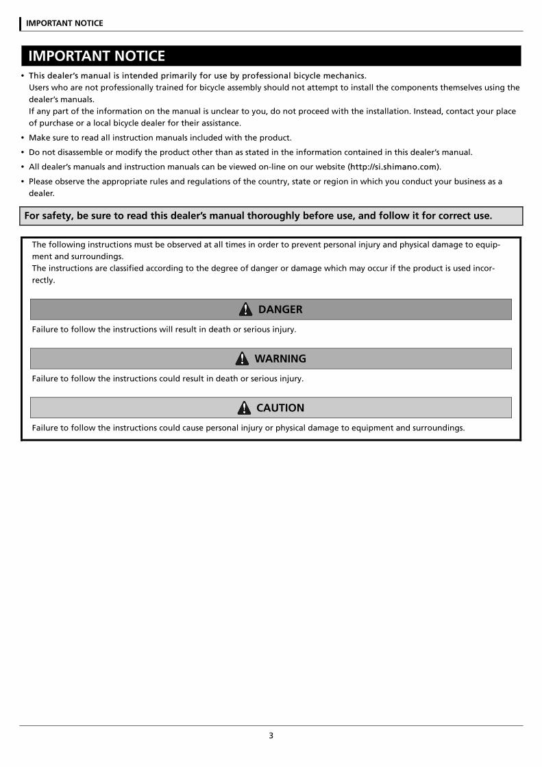
IMPORTANT NOTICE This dealer’s manual is intended primarily for use by professional bicycle mechanics.
Users who are not professionally trained for bicycle assembly should not attempt to install the components themselves using the dealer’s manuals. If any part of the information on the manual is unclear to you, do not proceed with the installation. Instead, contact your place of purchase or a local bicycle dealer for their assistance.
Make sure to read all instruction manuals included with the product.
Do not disassemble or modify the product other than as stated in the information contained in this dealer’s manual.
All dealer’s manuals and instruction manuals can be viewed on-line on our website (http://si.shimano.com).
Please observe the appropriate rules and regulations of the country, state or region in which you conduct your business as a dealer.
For safety, be sure to read this dealer’s manual thoroughly before use, and follow it for correct use.
The following instructions must be observed at all times in order to prevent personal injury and physical damage to equip-ment and surroundings. The instructions are classified according to the degree of danger or damage which may occur if the product is used incor-rectly.
DANGER
Failure to follow the instructions will result in death or serious injury.
WARNING
Failure to follow the instructions could result in death or serious injury.
CAUTION
Failure to follow the instructions could cause personal injury or physical damage to equipment and surroundings.
TO ENSURE SAFETY
4
TO ENSURE SAFETY
WARNING
Be sure to follow the instructions provided in the manuals when installing the product. It is recommended to use genuine Shimano parts only. If parts such as bolts and nuts become loose or dam-aged, the bicycle may suddenly fall over, which may cause serious injury. In addition, if adjustments are not carried out correctly, problems may occur, and the bicycle may suddenly fall over, which may cause serious injury.
Be sure to wear safety glasses or goggles to
protect your eyes while performing maintenance tasks such as replacing parts.
After reading the dealer's manual thoroughly, keep it in a safe place for later reference.
Be sure to also inform users of the following:
Intervals between maintenance depend on the use and riding circumstances. Clean the chain with an appropriate chain cleaner regularly. Never use alka-li based or acid based solvents, such as rust cleaners. If those solvents are used the chain might break and cause serious injury.
Check the chain for any damage (deformation or crack), skipping, or other abnormalities such as unin-tended gear shifting. If any problems are found, con-sult a dealer or an agency. The chain may break, and you may fall.
NOTE
Be sure to also inform users of the following:
If gear shifting operations cannot be carried out smoothly, clean the derailleur and lubricate all moving parts.
If looseness in the links is so great that gear shifting adjustments cannot be made, replace the derailleur.
The gears should be periodically washed with a neu-tral detergent. In addition, cleaning the chain with neutral detergent and lubricating it can be an effec-tive way of extending the life of the gears and the chain.
Products are not guaranteed against natural wear and deterioration from normal use and aging.
For maximum performance we highly recommend Shimano lubricants and maintenance products.
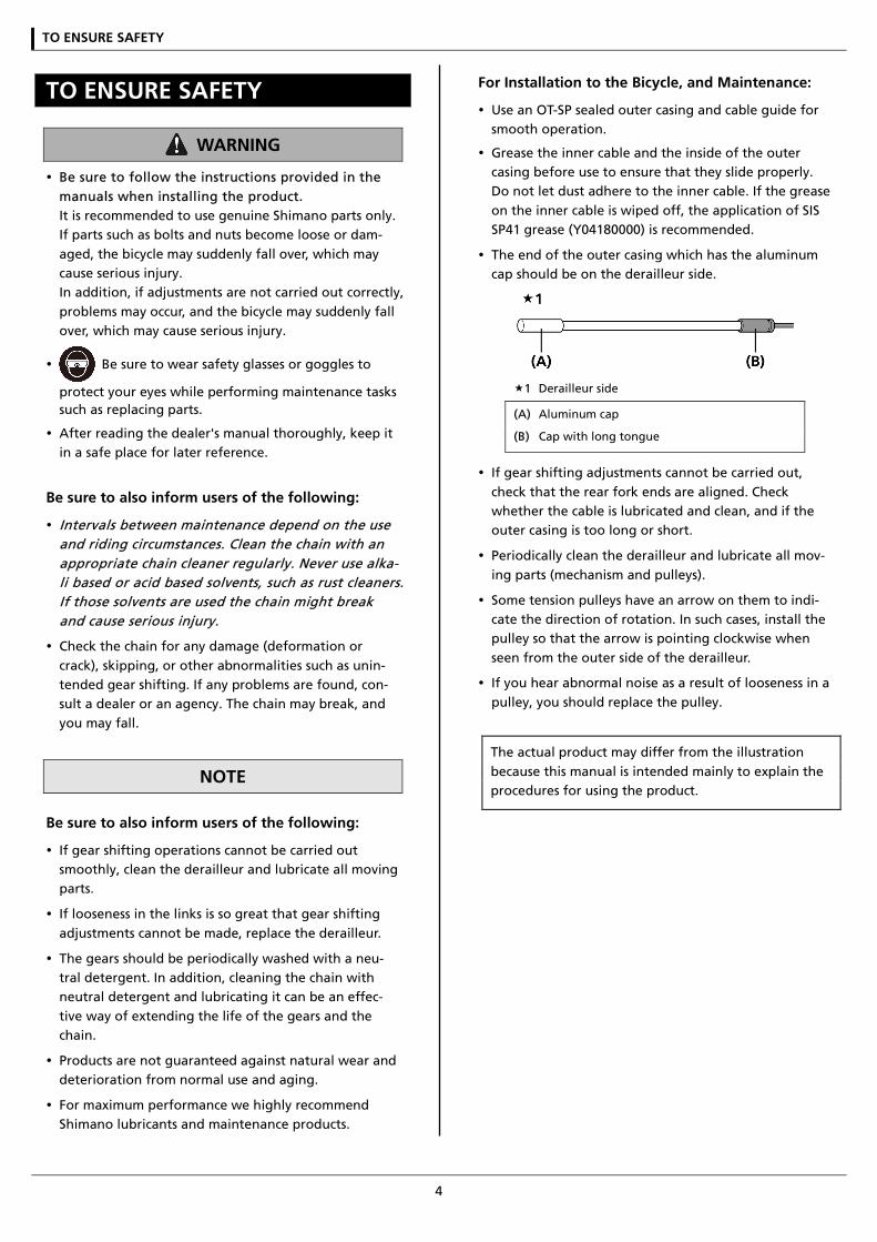
For Installation to the Bicycle, and Maintenance:
Use an OT-SP sealed outer casing and cable guide for smooth operation.
Grease the inner cable and the inside of the outer casing before use to ensure that they slide properly. Do not let dust adhere to the inner cable. If the grease on the inner cable is wiped off, the application of SIS SP41 grease (Y04180000) is recommended.
The end of the outer casing which has the aluminum cap should be on the derailleur side.
1 Derailleur side
(A) Aluminum cap
(B) Cap with long tongue
If gear shifting adjustments cannot be carried out, check that the rear fork ends are aligned. Check whether the cable is lubricated and clean, and if the outer casing is too long or short.
Periodically clean the derailleur and lubricate all mov-ing parts (mechanism and pulleys).
Some tension pulleys have an arrow on them to indi-cate the direction of rotation. In such cases, install the pulley so that the arrow is pointing clockwise when seen from the outer side of the derailleur.
If you hear abnormal noise as a result of looseness in a pulley, you should replace the pulley.
The actual product may differ from the illustration because this manual is intended mainly to explain the procedures for using the product.

LIST OF TOOLS TO BE USED

LIST OF TOOLS TO BE USED
6
LIST OF TOOLS TO BE USED The following tools are needed for installation, adjustment, and maintenance purposes.
Tool Tool Tool
3mm Allen key 5mm Allen key Slotted screwdriver
4mm Allen key Screwdriver[#2] Snap ring pliers

INSTALLATION
INSTALLATION
8
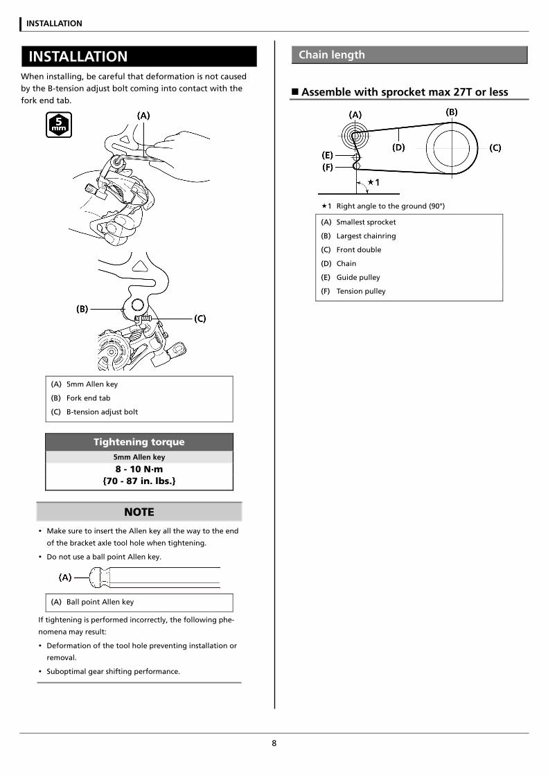
INSTALLATION When installing, be careful that deformation is not caused by the B-tension adjust bolt coming into contact with the fork end tab.
(A) 5mm Allen key
(B) Fork end tab
(C) B-tension adjust bolt
Tightening torque 5mm Allen key
8 - 10 N·m {70 - 87 in. lbs.}
NOTE
Make sure to insert the Allen key all the way to the end
of the bracket axle tool hole when tightening.
Do not use a ball point Allen key.
(A) Ball point Allen key
If tightening is performed incorrectly, the following phe-
nomena may result:
Deformation of the tool hole preventing installation or
removal.
Suboptimal gear shifting performance.
Chain length
Assemble with sprocket max 27T or less
1 Right angle to the ground (90°)
(A) Smallest sprocket
(B) Largest chainring
(C) Front double
(D) Chain
(E) Guide pulley
(F) Tension pulley
INSTALLATION
9
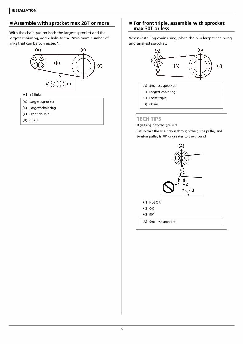
Assemble with sprocket max 28T or more
With the chain put on both the largest sprocket and the largest chainring, add 2 links to the "minimum number of links that can be connected".
1 +2 links
(A) Largest sprocket
(B) Largest chainring
(C) Front double
(D) Chain
For front triple, assemble with sprocket max 30T or less
When installing chain using, place chain in largest chainring and smallest sprocket.
(A) Smallest sprocket
(B) Largest chainring
(C) Front triple
(D) Chain
TECH TIPS Right angle to the ground
Set so that the line drawn through the guide pulley and
tension pulley is 90° or greater to the ground.
1 Not OK
2 OK
3 90°
(A) Smallest sprocket
INSTALLATION
10
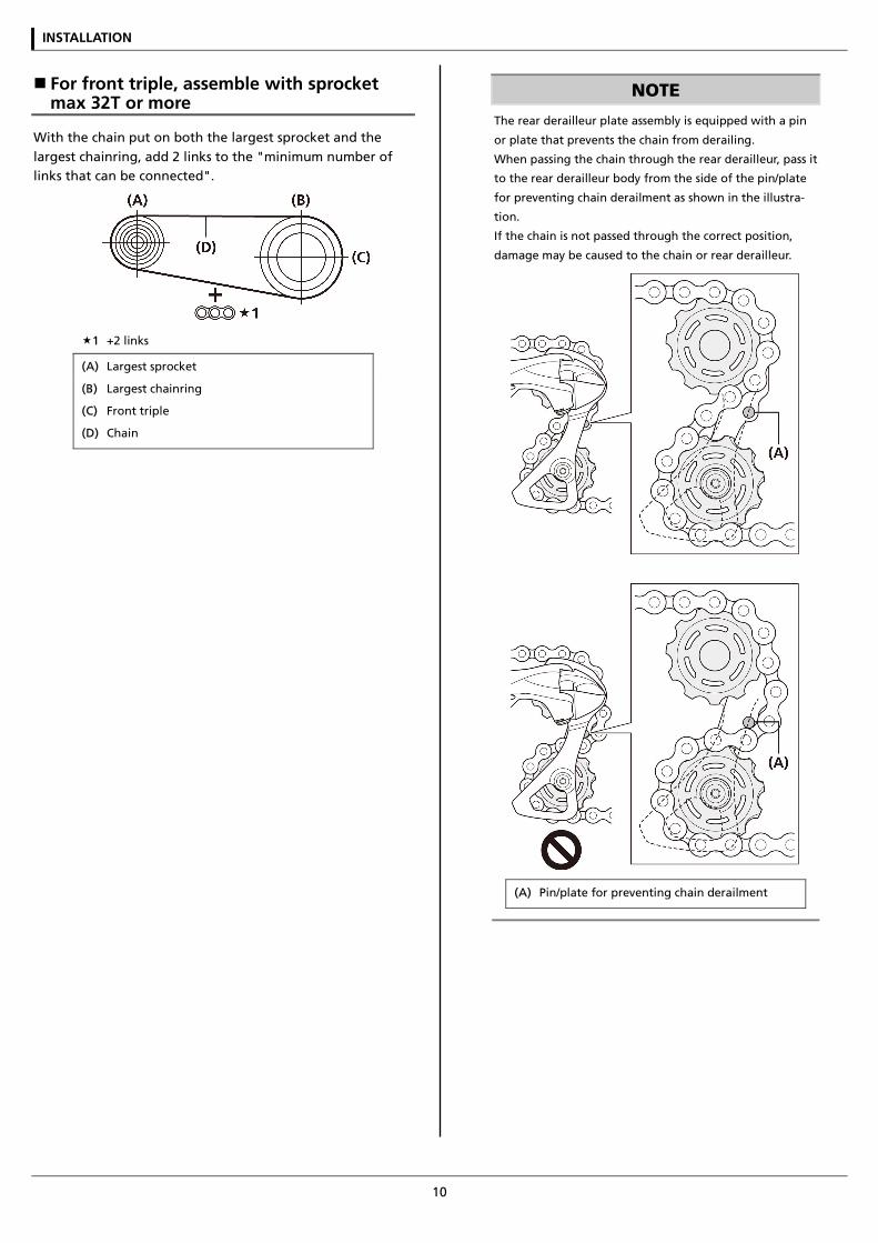
For front triple, assemble with sprocket max 32T or more
With the chain put on both the largest sprocket and the largest chainring, add 2 links to the "minimum number of links that can be connected".
1 +2 links
(A) Largest sprocket
(B) Largest chainring
(C) Front triple
(D) Chain
NOTE
The rear derailleur plate assembly is equipped with a pin
or plate that prevents the chain from derailing.
When passing the chain through the rear derailleur, pass it
to the rear derailleur body from the side of the pin/plate
for preventing chain derailment as shown in the illustra-
tion.
If the chain is not passed through the correct position,
damage may be caused to the chain or rear derailleur.
(A) Pin/plate for preventing chain derailment
ADJUSTMENT
ADJUSTMENT
12
ADJUSTMENT
SIS adjustment
Top adjustment
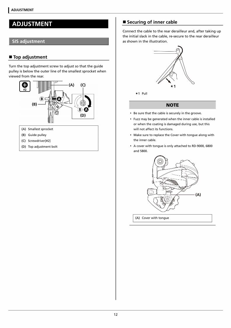
Turn the top adjustment screw to adjust so that the guide pulley is below the outer line of the smallest sprocket when viewed from the rear.
(A) Smallest sprocket
(B) Guide pulley
(C) Screwdriver[#2]
(D) Top adjustment bolt
Securing of inner cable
Connect the cable to the rear derailleur and, after taking up the initial slack in the cable, re-secure to the rear derailleur as shown in the illustration.
1 Pull
NOTE
Be sure that the cable is securely in the groove.
Fuzz may be generated when the inner cable is installed
or when the coating is damaged during use, but this
will not affect its functions.
Make sure to replace the Cover with tongue along with
the inner cable.
A cover with tongue is only attached to RD-9000, 6800
and 5800.
(A) Cover with tongue
ADJUSTMENT
13
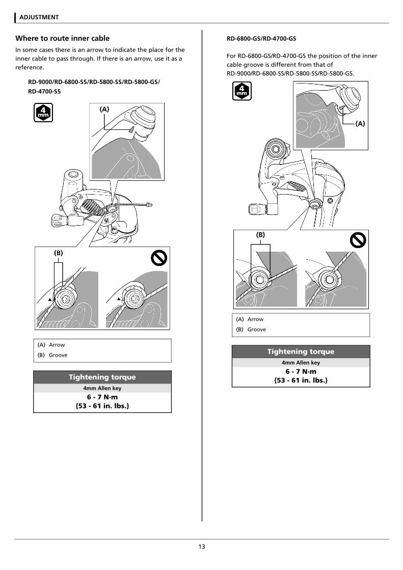
Where to route inner cable In some cases there is an arrow to indicate the place for the inner cable to pass through. If there is an arrow, use it as a reference.
RD-9000/RD-6800-SS/RD-5800-SS/RD-5800-GS/
RD-4700-SS
(A) Arrow
(B) Groove
Tightening torque 4mm Allen key
6 - 7 N·m {53 - 61 in. lbs.}
RD-6800-GS/RD-4700-GS
For RD-6800-GS/RD-4700-GS the position of the inner cable groove is different from that of RD-9000/RD-6800-SS/RD-5800-SS/RD-5800-GS.
(A) Arrow
(B) Groove
Tightening torque 4mm Allen key
6 - 7 N·m {53 - 61 in. lbs.}
ADJUSTMENT
14
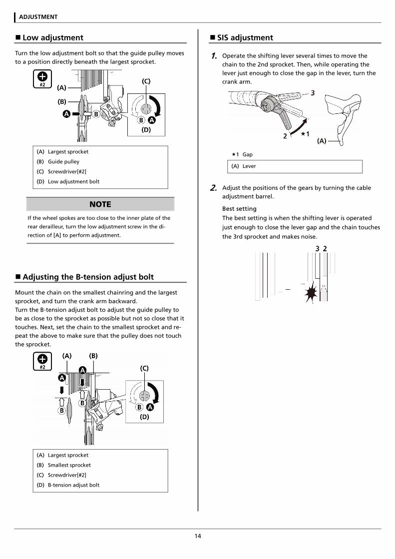
Low adjustment
Turn the low adjustment bolt so that the guide pulley moves to a position directly beneath the largest sprocket.
(A) Largest sprocket
(B) Guide pulley
(C) Screwdriver[#2]
(D) Low adjustment bolt
NOTE
If the wheel spokes are too close to the inner plate of the
rear derailleur, turn the low adjustment screw in the di-
rection of [A] to perform adjustment.
Adjusting the B-tension adjust bolt
Mount the chain on the smallest chainring and the largest sprocket, and turn the crank arm backward. Turn the B-tension adjust bolt to adjust the guide pulley to be as close to the sprocket as possible but not so close that it touches. Next, set the chain to the smallest sprocket and re-peat the above to make sure that the pulley does not touch the sprocket.
(A) Largest sprocket
(B) Smallest sprocket
(C) Screwdriver[#2]
(D) B-tension adjust bolt
SIS adjustment
1. Operate the shifting lever several times to move the chain to the 2nd sprocket. Then, while operating the lever just enough to close the gap in the lever, turn the crank arm.
1 Gap
(A) Lever
2. Adjust the positions of the gears by turning the cable adjustment barrel.
Best setting
The best setting is when the shifting lever is operated
just enough to close the lever gap and the chain touches
the 3rd sprocket and makes noise.
ADJUSTMENT
15
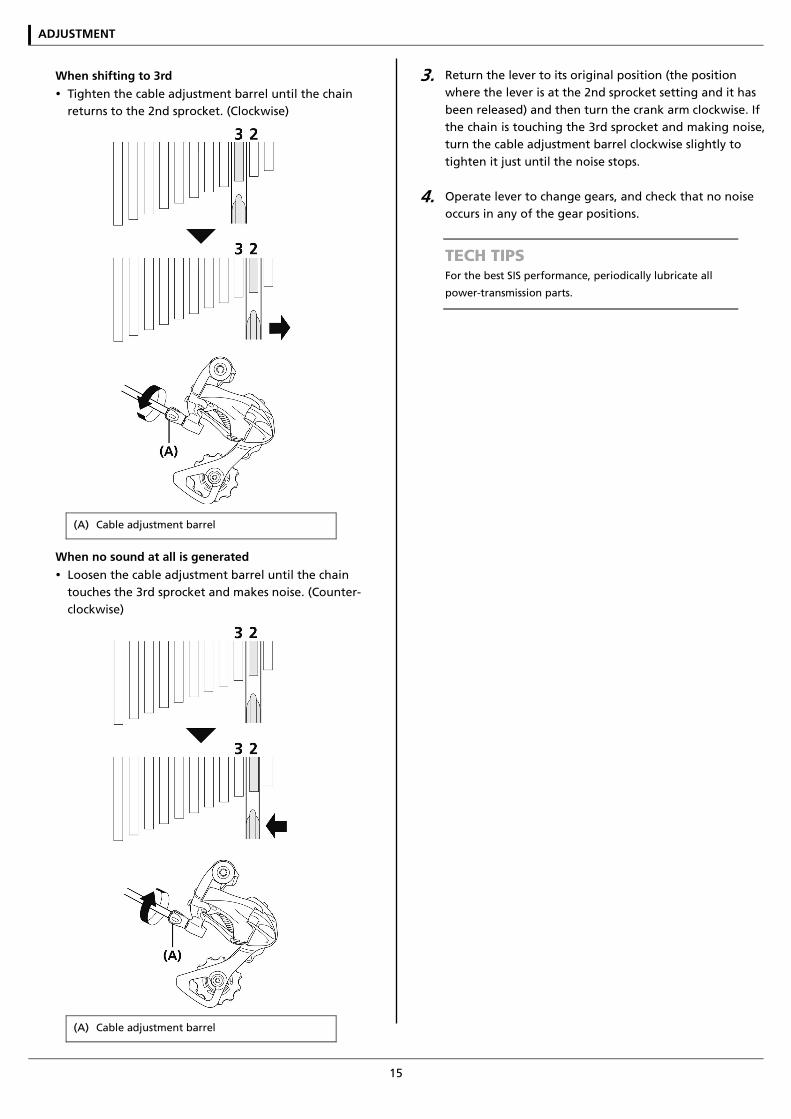
When shifting to 3rd
Tighten the cable adjustment barrel until the chain returns to the 2nd sprocket. (Clockwise)
(A) Cable adjustment barrel
When no sound at all is generated
Loosen the cable adjustment barrel until the chain touches the 3rd sprocket and makes noise. (Counter-clockwise)
(A) Cable adjustment barrel
3. Return the lever to its original position (the position where the lever is at the 2nd sprocket setting and it has been released) and then turn the crank arm clockwise. If the chain is touching the 3rd sprocket and making noise, turn the cable adjustment barrel clockwise slightly to tighten it just until the noise stops.
4. Operate lever to change gears, and check that no noise occurs in any of the gear positions.
TECH TIPS For the best SIS performance, periodically lubricate all
power-transmission parts.
ADJUSTMENT
16
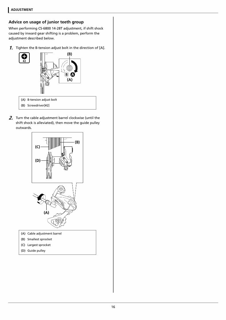
Advice on usage of junior teeth group When performing CS-6800 14-28T adjustment, if shift shock caused by inward gear shifting is a problem, perform the adjustment described below.
1. Tighten the B-tension adjust bolt in the direction of [A].
(A) B-tension adjust bolt
(B) Screwdriver[#2]
2. Turn the cable adjustment barrel clockwise (until the shift shock is alleviated), then move the guide pulley outwards.
(A) Cable adjustment barrel
(B) Smallest sprocket
(C) Largest sprocket
(D) Guide pulley
MAINTENANCE
MAINTENANCE
18
MAINTENANCE
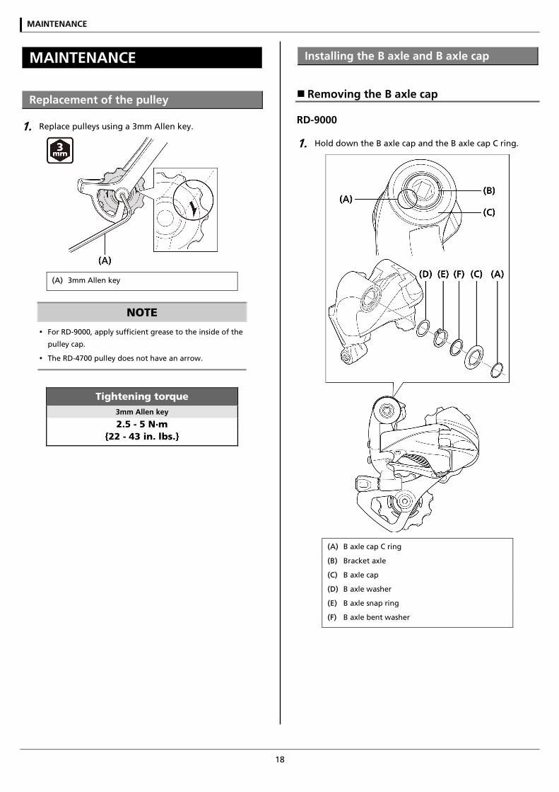
Replacement of the pulley
1. Replace pulleys using a 3mm Allen key.
(A) 3mm Allen key
NOTE
For RD-9000, apply sufficient grease to the inside of the
pulley cap.
The RD-4700 pulley does not have an arrow.
Tightening torque 3mm Allen key
2.5 - 5 N·m {22 - 43 in. lbs.}
Installing the B axle and B axle cap
Removing the B axle cap
RD-9000
1. Hold down the B axle cap and the B axle cap C ring.
(A) B axle cap C ring
(B) Bracket axle
(C) B axle cap
(D) B axle washer
(E) B axle snap ring
(F) B axle bent washer
MAINTENANCE
19
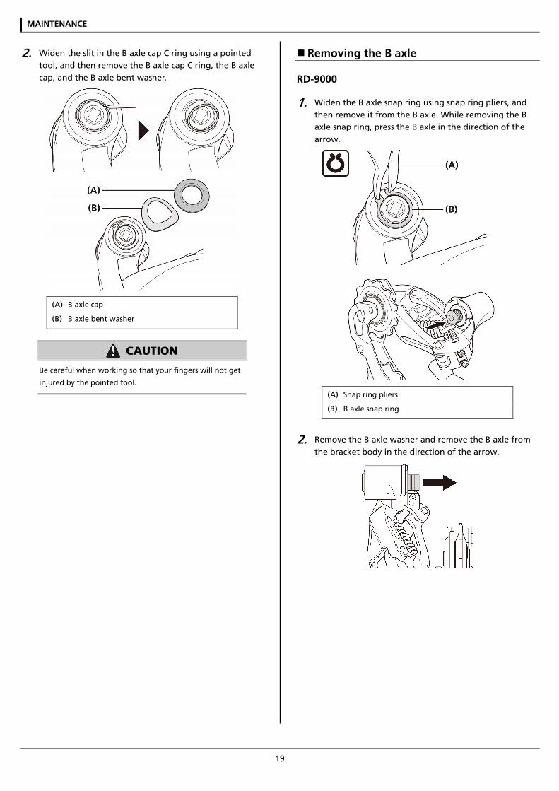
2. Widen the slit in the B axle cap C ring using a pointed tool, and then remove the B axle cap C ring, the B axle cap, and the B axle bent washer.
(A) B axle cap
(B) B axle bent washer
CAUTION
Be careful when working so that your fingers will not get
injured by the pointed tool.
Removing the B axle
RD-9000
1. Widen the B axle snap ring using snap ring pliers, and then remove it from the B axle. While removing the B axle snap ring, press the B axle in the direction of the arrow.
(A) Snap ring pliers
(B) B axle snap ring
2. Remove the B axle washer and remove the B axle from the bracket body in the direction of the arrow.
MAINTENANCE
20
RD-6800/RD-5800/RD-4700
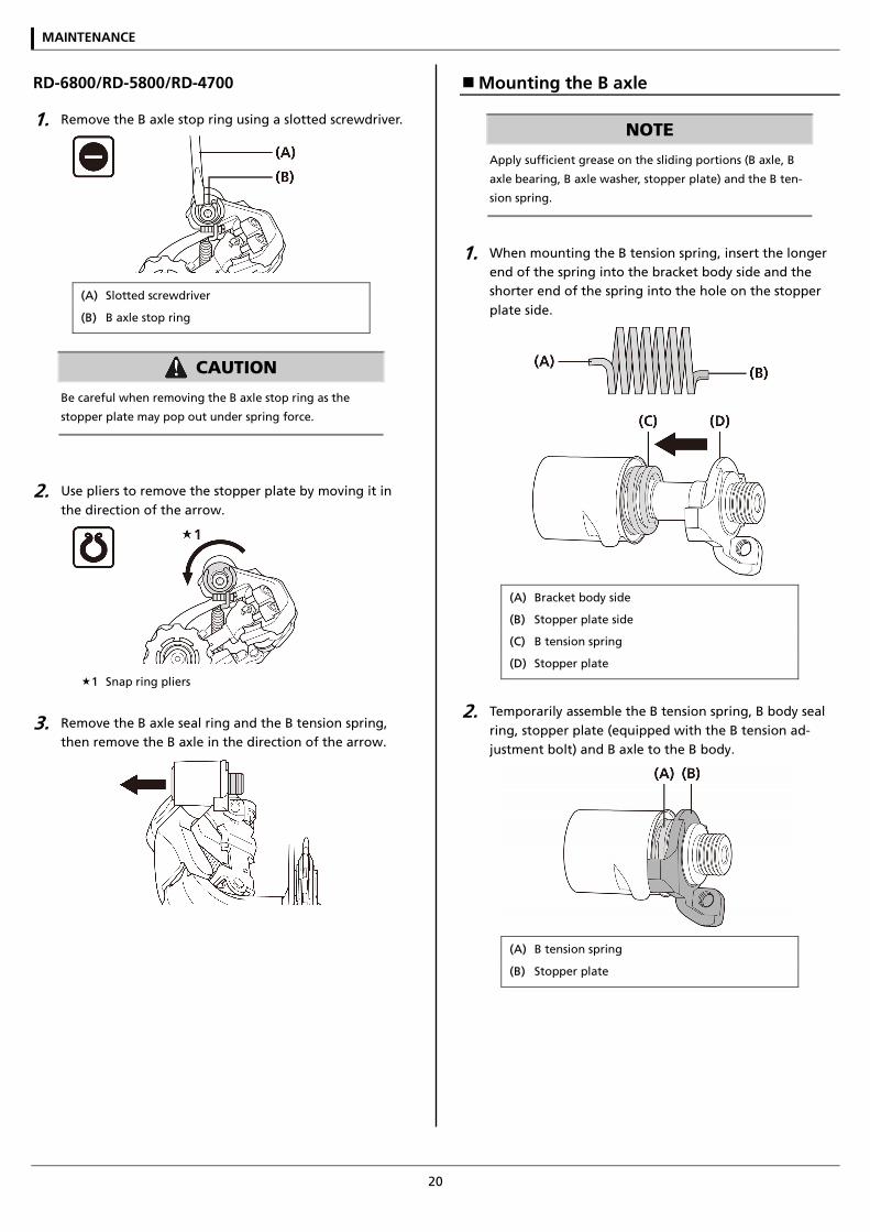
1. Remove the B axle stop ring using a slotted screwdriver.
(A) Slotted screwdriver
(B) B axle stop ring
CAUTION
Be careful when removing the B axle stop ring as the
stopper plate may pop out under spring force.
2. Use pliers to remove the stopper plate by moving it in the direction of the arrow.
1 Snap ring pliers
3. Remove the B axle seal ring and the B tension spring, then remove the B axle in the direction of the arrow.
Mounting the B axle
NOTE
Apply sufficient grease on the sliding portions (B axle, B
axle bearing, B axle washer, stopper plate) and the B ten-
sion spring.
1. When mounting the B tension spring, insert the longer end of the spring into the bracket body side and the shorter end of the spring into the hole on the stopper plate side.
(A) Bracket body side
(B) Stopper plate side
(C) B tension spring
(D) Stopper plate
2. Temporarily assemble the B tension spring, B body seal ring, stopper plate (equipped with the B tension ad-justment bolt) and B axle to the B body.
(A) B tension spring
(B) Stopper plate
MAINTENANCE
21
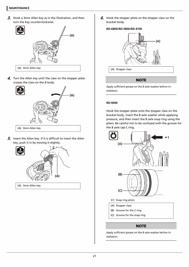
3. Hook a 3mm Allen key as in the illustration, and then turn the key counterclockwise.
(A) 3mm Allen key
4. Turn the Allen key until the claw on the stopper plate crosses the claw on the B body.
(A) 3mm Allen key
5. Insert the Allen key. If it is difficult to insert the Allen key, push it in by moving it slightly.
(A) 3mm Allen key
6. Hook the stopper plate on the stopper claw on the bracket body.
RD-6800/RD-5800/RD-4700
(A) Stopper claw
NOTE
Apply sufficient grease on the B axle washer before in-
stallation.
RD-9000
Hook the stopper plate onto the stopper claw on the bracket body, insert the B axle washer while applying pressure, and then insert the B axle snap ring using the pliers. Be careful not to be confused with the groove for the B axle cap C ring.
1 Snap ring pliers
(A) Stopper claw
(B) Groove for the C ring
(C) Groove for the snap ring
NOTE
Apply sufficient grease on the B axle washer before in-
stallation.
MAINTENANCE
22
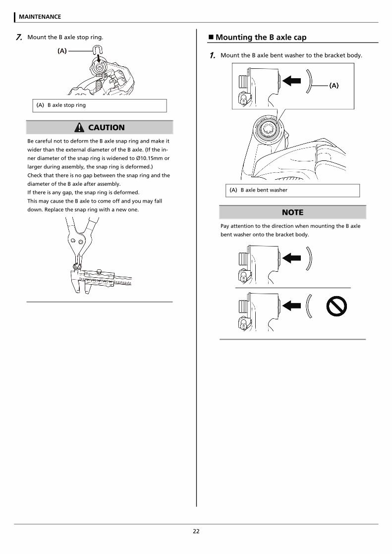
7. Mount the B axle stop ring.
(A) B axle stop ring
CAUTION
Be careful not to deform the B axle snap ring and make it
wider than the external diameter of the B axle. (If the in-
ner diameter of the snap ring is widened to Ø10.15mm or
larger during assembly, the snap ring is deformed.)
Check that there is no gap between the snap ring and the
diameter of the B axle after assembly.
If there is any gap, the snap ring is deformed.
This may cause the B axle to come off and you may fall
down. Replace the snap ring with a new one.
Mounting the B axle cap
1. Mount the B axle bent washer to the bracket body.
(A) B axle bent washer
NOTE
Pay attention to the direction when mounting the B axle
bent washer onto the bracket body.
MAINTENANCE
23
2. Mount the B axle cap and the B axle cap C ring. Check that the C ring is securely mounted to the groove on the B axle.
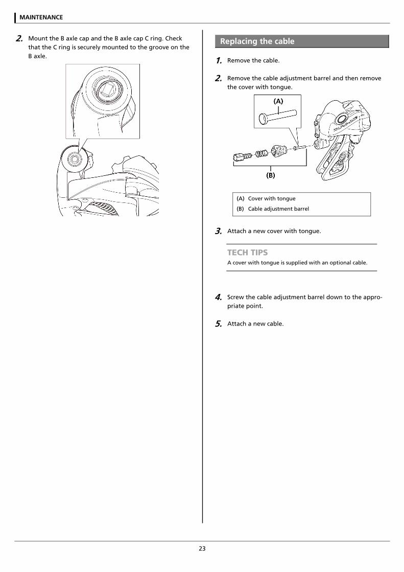
Replacing the cable
1. Remove the cable.
2. Remove the cable adjustment barrel and then remove the cover with tongue.
(A) Cover with tongue
(B) Cable adjustment barrel
3. Attach a new cover with tongue.
TECH TIPS A cover with tongue is supplied with an optional cable.
4. Screw the cable adjustment barrel down to the appro-priate point.
5. Attach a new cable.

Please note: specifications are subject to change for improvement without notice. (English) © March 2016 by Shimano Inc. HTR