Embed Size (px)
Citation preview

RoaPond
PrepaThe A PrepaThe U PrepaServicJune 2
d Mand Roa
red for Acton Wa
red by Universit
red withces 2011
nagemads, W
akefield
ty of Ne
h Suppor
ment PWakefi
d Watersh
ew Hamp
rt from N
Plan field, N
heds All
pshire S
NH Dep
for BraNH
liance
Stormwa
partment
ackett
ater Cent
t of Env
t and
ter
vironmenntal

i
TABLE OF CONTENTS TABLE OF CONTENTS ............................................................................................................................................ I
LIST OF TABLES .................................................................................................................................................... III
LIST OF FIGURES .................................................................................................................................................. III
ACKNOWLEDGEMENTS ....................................................................................................................................... V
EXECUTIVE SUMMARY ......................................................................................................................................... 1
BACKGROUND .......................................................................................................................................................... 3
INTRODUCTION ....................................................................................................................................................... 4
STEPS IN THE ROAD MANAGEMENT PLAN PROCESS .................................................................................................. 6
LONG-TERM MAINTENANCE OF ROADSIDE DRAINAGE IMPROVEMENTS ......................................... 7
OPPORTUNITIES FOR IMPROVEMENTS FOR REDUCTION OF SEDIMENT LOAD ............................... 7
ROAD MANAGEMENT IMPROVEMENTS .......................................................................................................... 8
ROAD INVENTORY AND CONDITIONS ASSESSMENT ................................................................................... 8
METHODS DESCRIPTION ............................................................................................................................................ 8 DETAILED INVENTORY DESCRIPTION ...................................................................................................................... 11
BR001: 405 Brackett Road ................................................................................................................................. 11 BR002: Lovell Heights and Brackett Road Crossing ........................................................................................ 11 BR003: 501 Brackett Road ................................................................................................................................. 13 BR004: Near Sunshine Acres, Brackett Road .................................................................................................... 14 BR005: 524 – 536 Brackett Road ....................................................................................................................... 15 BR006: 629-654 Brackett Road ......................................................................................................................... 15 BR007: 654 Brackett Road ................................................................................................................................. 16 BR008: 714 Brackett Road ................................................................................................................................. 17 BR009: 726 and 740 Brackett Road ................................................................................................................... 18 BR010: Between 772 – 758 Brackett Road ........................................................................................................ 19 BR011: Roadway running downhill to 1023 Brackett Road .............................................................................. 20 BR012: Forested area uphill and across from 1023 Brackett Road .................................................................. 21 BR013: End of Brackett Road, beginning of Pond Road. .................................................................................. 21 PR001: 240 Pond Road ...................................................................................................................................... 22 PR002: 358 Pond Road ...................................................................................................................................... 23
COST ESTIMATES .................................................................................................................................................. 23
POLLUTANT LOAD ESTIMATES ........................................................................................................................ 24
TREATMENT STRATEGY PERFORMANCE .................................................................................................................. 25 PRIORITIZATION BY LOAD AND COST ...................................................................................................................... 25
RECOMMENDED STRATEGIES .......................................................................................................................... 27
ROAD MAINTENANCE .............................................................................................................................................. 27 Erosion and Sedimentation Control in Roadside Ditching Practices ................................................................ 27 Recommended Equipment .................................................................................................................................. 28 Road Materials ................................................................................................................................................... 28 Crowning and Grading ...................................................................................................................................... 29 Dust Control Strategies ...................................................................................................................................... 30 Chemically Treated Roads ................................................................................................................................. 30
STRUCTURAL STRATEGIES ....................................................................................................................................... 31 Sediment basins and Ditch Turnouts .................................................................................................................. 31 Deep Sump Catch Basins ................................................................................................................................... 32 Hooded Outlets and Catch Basin Inserts ........................................................................................................... 33

ii
Infiltration Basins .............................................................................................................................................. 34 Media Filter ....................................................................................................................................................... 35 Infiltration trenches ............................................................................................................................................ 35 Dry Well ............................................................................................................................................................. 36 Road Crossing and Conveyance ........................................................................................................................ 37 Energy Dissipaters ............................................................................................................................................. 39
NON-STRUCTURAL STRATEGIES .............................................................................................................................. 40 Vegetated Buffers and Filter Strips .................................................................................................................... 40 Improved Regulations and Ordinances .............................................................................................................. 41 Formation of a Road Association....................................................................................................................... 42
GENERAL CHARACTERIZATION OF LAND-USE WITHIN WATERSHED .............................................. 42
Un-Improved Gravel and Low-Volume Roads ................................................................................................... 42 Residential .......................................................................................................................................................... 43
REFERENCES .......................................................................................................................................................... 44
APPENDIX A: TERMINOLOGY .......................................................................................................................... 47
APPENDIX : WHEN TO PAVE ............................................................................................................................. 50
iii
LIST OF TABLES
Table 1: Road Inventory and Assessment with Estimated Annual Sediment Load ....................... 10 Table 2: Cost Estimates for Recommended Improvements for Materials, Equipment, and Labor....................................................................................................................................................... 24 Table 3: Treatment Performance of Recommended Strategies for Sediment and Phosphorus .... 25 Table 4: Table of Inventory Ranked by Estimated Sediment Load, Reductions, and Cost ........... 26 Table 5: Culvert Types, Advantages, and Disadvantages (MaineDEP 2010). ............................. 38 Table 6: Predominant Pollutant Sources for Un-Improved Gravel and Low-Volume Roads ...... 42 Table 7: Predominant Pollutant Concentrations for Un-Improved Gravel and Low-Volume Roads............................................................................................................................................. 43 Table 8: Predominant Pollutant Sources for Residential Land-Use ............................................ 43 Table 9: Predominant Pollutant Concentrations for Residential Land-Use ................................ 43
LIST OF FIGURES
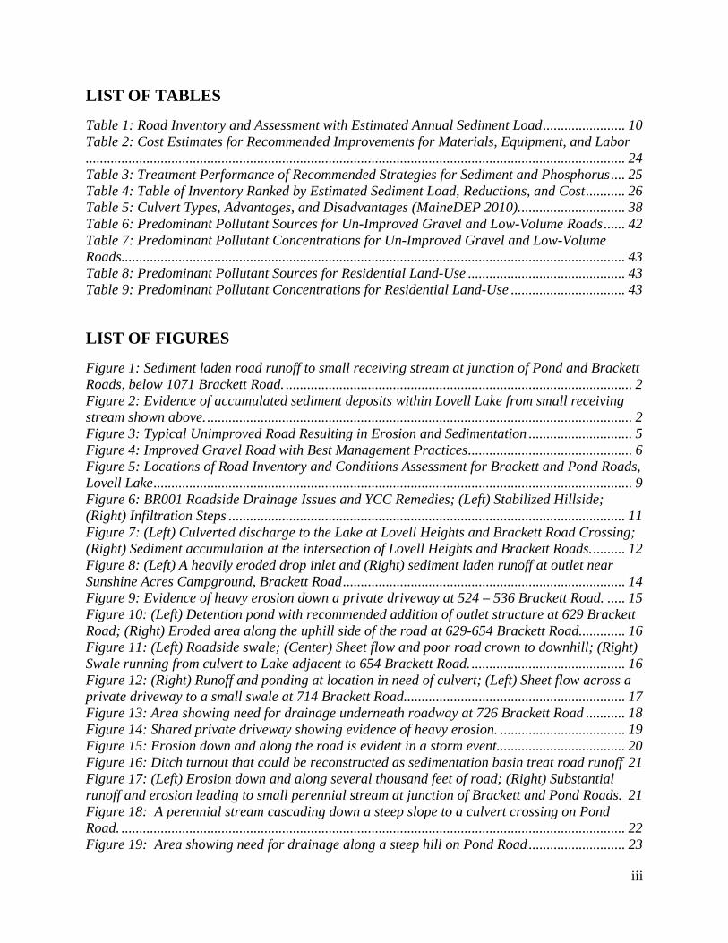
Figure 1: Sediment laden road runoff to small receiving stream at junction of Pond and Brackett Roads, below 1071 Brackett Road. ................................................................................................. 2 Figure 2: Evidence of accumulated sediment deposits within Lovell Lake from small receiving stream shown above. ....................................................................................................................... 2 Figure 3: Typical Unimproved Road Resulting in Erosion and Sedimentation ............................. 5 Figure 4: Improved Gravel Road with Best Management Practices .............................................. 6 Figure 5: Locations of Road Inventory and Conditions Assessment for Brackett and Pond Roads, Lovell Lake ...................................................................................................................................... 9 Figure 6: BR001 Roadside Drainage Issues and YCC Remedies; (Left) Stabilized Hillside; (Right) Infiltration Steps ............................................................................................................... 11 Figure 7: (Left) Culverted discharge to the Lake at Lovell Heights and Brackett Road Crossing; (Right) Sediment accumulation at the intersection of Lovell Heights and Brackett Roads. ......... 12 Figure 8: (Left) A heavily eroded drop inlet and (Right) sediment laden runoff at outlet near Sunshine Acres Campground, Brackett Road ............................................................................... 14 Figure 9: Evidence of heavy erosion down a private driveway at 524 – 536 Brackett Road. ..... 15 Figure 10: (Left) Detention pond with recommended addition of outlet structure at 629 Brackett Road; (Right) Eroded area along the uphill side of the road at 629-654 Brackett Road............. 16 Figure 11: (Left) Roadside swale; (Center) Sheet flow and poor road crown to downhill; (Right) Swale running from culvert to Lake adjacent to 654 Brackett Road. ........................................... 16 Figure 12: (Right) Runoff and ponding at location in need of culvert; (Left) Sheet flow across a private driveway to a small swale at 714 Brackett Road. ............................................................. 17 Figure 13: Area showing need for drainage underneath roadway at 726 Brackett Road ........... 18 Figure 14: Shared private driveway showing evidence of heavy erosion. ................................... 19 Figure 15: Erosion down and along the road is evident in a storm event.................................... 20 Figure 16: Ditch turnout that could be reconstructed as sedimentation basin treat road runoff 21 Figure 17: (Left) Erosion down and along several thousand feet of road; (Right) Substantial runoff and erosion leading to small perennial stream at junction of Brackett and Pond Roads. 21 Figure 18: A perennial stream cascading down a steep slope to a culvert crossing on Pond Road. ............................................................................................................................................. 22 Figure 19: Area showing need for drainage along a steep hill on Pond Road ........................... 23

iv
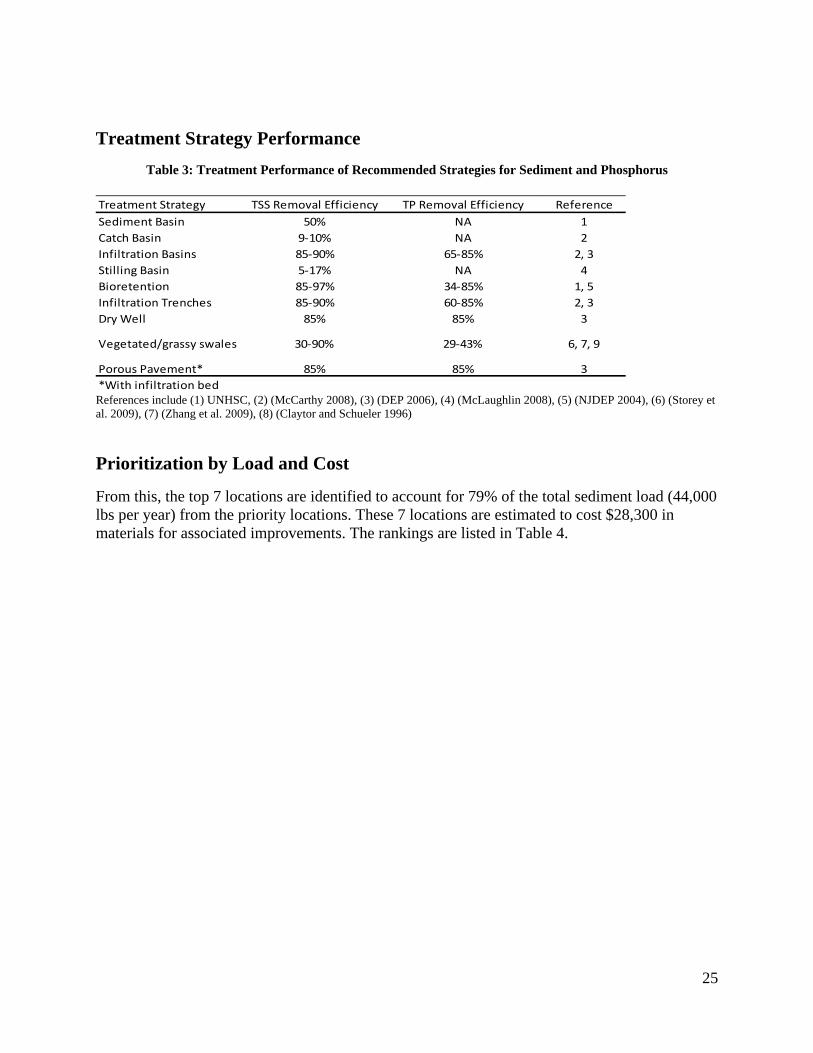
Figure 20: Crown profile (YCSWCD 2007). ................................................................................ 29 Figure 21: Sand and vegetation build-up prevents drainage to sides of road(YCSWCD 2007). . 30 Figure 22: Ditch Turnout (MaineDEP 2010). .............................................................................. 31 Figure 23: Sediment Basin located at Upper Hague Brook in the Lake George watershed (LGA)........................................................................................................................................................ 32 Figure 24: Catch Basin (LGA). .................................................................................................... 33 Figure 25: Typical Installation of a hooded outlet (Round Snout Shown) (BMP 2011a) ............ 34 Figure 26: Infiltration Basin (Waterkeeper 2008)........................................................................ 35 Figure 27: Bioretention system retrofit ........................................................................................ 35 Figure 28: Infiltration Trench (Akan 2002).................................................................................. 36 Figure 29: Infiltration Trench (Waterkeeper 2008). .................................................................... 36 Figure 30: Dry Well (LGA) Figure 31: Dry Well (Waterkeeper 2008). .................................. 37 Figure 32: Concrete box culvert with wing walls (USFS 2005). .................................................. 38 Figure 33: Rubber Razor (MaineDEP 2006). .............................................................................. 39 Figure 34: Debris rack well upstream of culvert (USFS 2005). ................................................... 40 Figure 35: Filter Strip Plan and Profile View (Claytor and Schueler 1996) .............................. 41

v
ACKNOWLEDGEMENTS Funding for this project was provided in part by a grant from the NH Department of Environmental Services with funding from the US Environmental Protection Agency under Section 319 of the Clean Water Act. Project Sponsors NH Department of Environmental Services Project Team UNH Stormwater Center James Houle, CPSWQ Robert Roseen, PhD, PE, D.WRE Wakefield Road Agent Dan Davis Acton Wakefield Watersheds Alliance Linda Schier NHDES Coastal Watershed Coordinator Sally Soule

1
Road Management Plan for Brackett and Pond Roads, Wakefield, NH Report by the University of New Hampshire Stormwater Center
EXECUTIVE SUMMARY
The purpose of the Road Management Plan is to address the declining water quality of Lovell Lake caused by runoff from Brackett and Pond Roads carrying sediment and phosphorus. Unimproved roads are commonplace in the Lakes Region of New Hampshire in an area with a substantial seasonal population. Unimproved roads and associated maintenance are well documented as major sources of sediment and phosphorus to surface water and may account for as much as 80% of the sediment load and 40% of the phosphorus load within a watershed. Studies have shown that during highly erosive storm events, sediment concentrations may be observed to exceed 100,000 mg/L with averages for gravel roads >3,000 mg/l (Clinton and Vose 2003) whereas a typical low use paved road would be ~100 mg/L (Hagen and Walker 2006). The impacts from these sediment laden waters can be substantial and directly impact the value, aesthetics, and usability of our lakes. As seasonal populations grow and become permanent, the number of road miles and driveways will increase, and maintenance demands for these unimproved surfaces will increase. Another issue of concern is that road maintenance practices, while improving road drainage, often contribute significantly to erosion and sedimentation. The process of improving roadside conveyance through ditching is routine and a necessary element of road maintenance. However, the addition of erosion and sedimentation control practices to this routine maintenance will reduce the threat to surface waters. A range of strategies exist to reduce impacts ranging from practical road maintenance techniques, to road and drainage improvements, and non-structural approaches (i.e. catch basin cleaning, vegetative stabilization) targeted to minimize erosion and sedimentation. This Road Management Plan (RMP) presents recommendations for Brackett and Pond Roads, and a review of locations identified to be primary problem areas. The locations are prioritized for cost and sediment load. This review finds that by addressing the top 7 of the 14 identified locations, over 44,000 lbs of sediment per year can be eliminated from reaching Lovell Lake. That represents 79% of the total estimated sediment load from the 14 sites. These 7 improvements are estimated to cost $28,300. Costs include only materials. Labor and equipment are not included as these are anticipated to be a component of existing operations and maintenance by municipal staff. Costs do not represent detailed design costs which are still required and are for planning purposes only. These estimates are useful for planning, pursuing additional funding and illustrating the relative ranking of each location. The approaches and techniques recommended in the RMP can all be implemented by existing Town staff. Recommendations include additional equipment and labor demands, both available

Figure
Figure 2:
for purchservice v A generasites, treasized dragravel chcontrols pstabilized
1: Sediment l
Evidence of a
hase or hire. vehicle.
alized managatment strateainage, 2) wiheck dams), post culvert d conveyanc
aden road run
accumulated s
The equipm
gement approegies were veith upstream 3) installatiothat could fi
ce to the lake
noff to small rbelow 10
sediment depo
ment expense
oach for Braery similar asedimentati
on of road crilter, infiltrate.
receiving strea71 Brackett R
osits within Loabove.
s range from
ackett and Poand consistedion structurerossings for ste and dissip
am at junctionRoad.
ovell Lake fro
m minimal to
ond Roads isd of: 1) estab
es (i.e. hoodesurface runopate high vel
n of Pond and
m small receiv
o that equiva
s described bblishing stabed deep sumpoff, 4) use oflocity flows,
Brackett Roa
ving stream sh
alent to a larg
below. At mble, adequatep catch basinf water quali, and 5)
2
ads,
hown
ge
most ely ns, ity

3
BACKGROUND
Lovell Lake is a 538-acre lake that is both spring-fed and fed by small streams, including Horse Brook to the northwest. Lovell Lake outlets into the Branch River in the village of Sanbornville to the west. From here, the Branch River flows in a southeasterly direction to Milton, NH where it joins the Salmon Falls River on the Maine-New Hampshire border. The Salmon Falls River eventually empties into the tidal waters of the Piscataqua River in Portsmouth, New Hampshire. Lovell Lake is a Tier 1 waterbody, which means it marginally supports water quality standards due to elevated levels of certain indicators such a phosphorus and chlorophyll a. According to the Salmon Falls Headwater Lakes Watershed Management Plan, the phosphorus levels in Lovell Lake need to be reduced in order for the lake meet the NHDES criteria for High Quality Waters (AWWA and FB Environmental 2010). From a community perspective, lakes are one the most valuable natural resources providing for recreation, relaxation, aesthetic appeal and bringing in much needed tourism dollars and revenue to the adjacent towns. Lakes and their surrounding lands also provide habitat for plants, wildlife and aquatic life. The largest challenge to protecting area Lakes is the threat of untreated runoff from impervious surfaces and developments. Soil erosion, in particular, is the single greatest source of pollution to Lovell Lake. Soil contains the nutrient phosphorus, which has the potential to promote algae blooms when it enters a lake in large quantities. As the algae die off, the water becomes depleted of oxygen, affecting fish and animals that depend on the lake water. September 2008, in an effort to address this concern, a team of 32 local volunteers and technical staff from the Lovell Lake Association, Acton Wakefield Watersheds Alliance, York County SWCD, NH DES, and Maine DEP conducted a survey of the watershed and identified 161 sites that are contributing polluted runoff to Lovell Lake. Teams documented polluted runoff sources from roads, properties, driveways, and shorelines using cameras and standardized field data sheets. Survey results and recommendations were compiled in the Lovell Lake Watershed Survey Report. The survey teams identified 161 sites that were either impacting or had the potential to impact water quality in Lovell Lake. Ten of the 38 sites associated with roads were along Brackett and Pond roads as well as many driveway and residential sites that were a result of water flowing off of those roads. Many of the residents along Brackett and Pond roads have developed strategies to prevent their driveways and properties from washing into the lake and the AWWA Youth Conservation Corps has installed erosion control measures at nine associated properties but the problem must be managed at the source. In 2010, AWWA was awarded a NHDES Watershed Assistance grant to undertake some of the recommendations from the Plan including partnering with the UNH Stormwater Center to find solutions to the chronic drainage problems along Brackett and Pond roads. This report is intended as a guide for Wakefield town officials and the Public Works department as they set priorities for road maintenance projects throughout the Town.

4
INTRODUCTION
Many of the unimproved roads used today were designed with very different considerations than new roadways. Most have evolved from primitive trails and pathways once used by early settlers. As needs and traffic increased, these paths became roads which were gradually improved with gravel or crushed stone. For the most part, designs and maintenance were simple and minimal. Repairs and improvements would be in response to complaints or damage from erosion from large storm events with the primary goals of elimination of ruts, stabilization of surfaces and eliminating mud. As development, population and tourism have increased, roads are exposed to ever-increasing weights and volumes of traffic. This in combination with increasingly intense rain events has resulted in an increased need for road maintenance and reconstruction budgets. The development and implementation of a Road Management Plan is a means for controlling and managing the increased demands pro-actively. This process can reduce expenditures associated with frequent maintenance by identifying and targeting problem areas for drainage improvements. This process can also reduce the impacts to the lakes and streams, a central component to the surrounding communities. Studies have shown that erosion from gravel roads can account for more than 80 percent of the sediment threatening water quality (Van Lear, et al. 1995, Reidel 2003). Resources to better manage gravel roads are plentiful. This report references two primary manuals, the Gravel Road Maintenance Manual (MEDEP 2010), and the Gravel Roads Maintenance and Design Manual (USDOT, 2000). Recent guidance prescribes a general approach involving stabilized ditches, use of sedimentation basins, and sizing drainage infrastructure such that it can adequately convey large storm events without overwhelming the system and causing severe destabilization and washout. Other examples may include regrading road profiles/elevations to support natural drainage patterns, stormwater conveyances above and below the surface of roadways, and improving and stabilizing channels and ditch maintenance procedures (Scheetz and Bloser 2008). Historically, common road design for unimproved roads was basic, and simply conveyed water off and into roadside ditches, eventually to streams and surface waters ( Figure 3). Ditches may not have been stabilized, and may or may not have included the use of culverts and catch basins. Without the use of culverts and catch basins, drainage is left to wash over road surfaces, and pond in low lying areas. Concentrated flow over the gravel surfaces can lead to road washout, and the need for frequent maintenance. Poor drainage in low areas can result in ponded areas, flooding, muddy surfaces, and impeded travel. Common maintenance of roadside ditches involves the cleaning and removal of accumulated materials including leaves, sediment, and vegetation which reduce the capacity for roadside conveyance. Ditch clearing is commonly performed by the excavation of materials with a backhoe. However, the removal of materials, while improving the conveyance for the short-term, typically leaves behind unstabilized channels prone to erosion. Where the vegetation has been removed, the channel sidewalls cut steeply, and large armor stone removed, channel erosion will occur.

Figure 3: T
Unimprodepositedmaintenagenerallyattached was showNew Yordevelope(Waterkephosphor(AWWAcontrolle
The strattechniquestabilizatdrainage,check dapost culvconveyan
Typical Unim
oved roads and into streamance. In addiy associated to road sedim
wn in a total rk. The budged areas whiceeper 2008). rus comes fr
A 2010). A lad by sedime
egies recomes, road and tion of erodib, 2) with upsms), 3) insta
vert that coulnce to the lak
mproved Road
nd ditch maims and lakes,ition to increwith runoff ments, and iphosphorus
get showed thch accountedIn Wakefiel
rom developearge majorityent reduction
mmended in thdrainage imble soils. Thstream sedimallation of rold filter, infilke.
Resulting in E
intenance pr, in addition eased sedimefrom imperv
is often an inbudget that hat 43% of ad for only 5%ld, which is ed areas, why of phosphon.
he RMP incmprovementshese strategiementation struoad crossingsltrate and dis
Erosion and S
actices haveto requiring
ent loading, tvious areas. Nncreased conwas conduc
all the phosp% of the landless develop
hich account orus is assoc
lude a focuss, and non-stes include: 1uctures (i.e. s for surfacessipate high
Sedimentation
e resulted in g significant the majorityNutrients, su
ncern with uncted for the Lphorus that ed area withinped than Lakt for 4% of thciated with se
s on practicatructural app1) establishin
hooded deee runoff, 4) u
velocity flo
tons of sedimamounts of
y of phosphouch as phospnimproved gLake Georgeentered the lan the watershke George, 1he land area ediment and
al road maintproaches focung stable, adp sump catc
use of water ws, and 5) s
ment being ongoing
orus loading phorus, are ogravel roads.e Watershed ake was fromhed 6% of the in the water
d can thus be
tenance used on
dequately sizch basins, graquality cont
stabilized
5
is often . This in
m the
rshed e
ed avel trols

Steps in
The gene
1. Incodrsu
2. Aanpgca
3. Sdre
4. Pal
Figure
n the Road
eral approach
nventory ofontrols assocrainage pathuch as slope
Assessment ond immediatotential for eeneral repairalculated forelection of aeveloped forelative cost e
Prioritizationlso conducte
4: Improved G
d Manage
h and metho
f roads: an iciated with B
hs, approximand distanc
of road condtely followinerosion examr or reconstrr each area. appropriater the thirteeneffectivenessn scheme: Ced in order to
Gravel Road w
ment Plan
dology used
initial inventBrackett Roa
mations of tote to receivindition: Multng large rainmined. Thirteruction. Asse
e treatment n identified ls, treatment Cost projecto prioritize a
with Best Man
n Process
d in this stud
tory was takad. This incltal sub-drainng water bodtiple field tri
n events. Draeen potentiaessments for
strategies:locations. Steffectivenesions and pol
areas in need
nagement Pra
dy is outlined
ken of the influded man-mnage areas andies. ips and site tainage patter
al sites were r pollutant lo
Planning letrategies we
ss and long tllutant load rd of attention
actices
d in this sect
frastructure amade and natnd general si
trips were plrns were docidentified as
oad contribut
evel treatmenre selected b
term managereduction asn. Planning l
ion
and drainageturally evideite characteri
lanned durincumented ans in need of tions were th
nt strategies based on theeability. sessments wlevel solution
6
e ent istics
ng nd
hen
were ir
were ns,

7
costs, and treatment efficiencies were developed for all locations and prioritized in this report according to the following criteria:
a. Ranked by existing load b. Ranked by load reductions c. Ranked by cost
LONG-TERM MAINTENANCE OF ROADSIDE DRAINAGE IMPROVEMENTS
The following recommendations are included for maintenance of roadside drainage. Routine maintenance and the inclusion of sedimentation and erosion control practices is an essential element of long-term reduction in sediment load. The goal of ditch maintenance practices is to minimize disturbance of soils, and when excavation is needed, to employ appropriate stabilization methods.
1. Continued stabilization of roadside ditches through vegetation and stone, and gravel check dams
2. Application of hydroseed following road ditching practices to minimize unstabilized soils.
3. Removal of leaf-litter with leaf vacuums in manner that minimizes unstabilized soils 4. Removal of sediment from sedimentation basins, deep sump catch basins, and check
dams.
OPPORTUNITIES FOR IMPROVEMENTS FOR REDUCTION OF SEDIMENT LOAD
Structural methods and strategies for reduction of sediment load focus on the following approaches:
1. The use installation of deep sump catch basins installed with hooded outlets as a pretreatment mechanism
2. Stabilized conveyance across/under roadways 3. Application of sedimentation/infiltration basin/filtration for volume reduction 4. Application of energy dissipater 5. Stabilized conveyance to surface waters through the application of hydroseed and stone
stabilization. These practices prevent the substantial and continued accumulation of sediment through erosion of unstabilized areas. In addition, sediment removal and volume reduction practices are added. Volume reduction for small storms is a relatively simple practice. For this region, 50% of storms are less than 0.17 inches in depth, and 75% are less than 0.45 inches in depth1. Sizing infiltration practices for small storms can reduce the impact from the vast majority of rainfall events.
1 Based on a frequency analysis of Durham daily rainfall data from 1926-2003.
8
ROAD MANAGEMENT IMPROVEMENTS
1. Crowning of roads to upslope side 2. Paving of chronic problem and high grade areas 3. Regrading and Resurfacing 4. Road materials characterization and composition for road base and road surface
ROAD INVENTORY AND CONDITIONS ASSESSMENT
The Brackett and Pond Roads inventory and conditions assessment were performed on multiple occasions during 2009, 2010, and 2011. Initial review was done in collaboration with an AWWA conditions assessment for problem areas as part of the YCC efforts. The UNHSC returned to do an inventory and assessment during a 2.75”2 storm event on August 25, 2010, and returned on multiple occasions in 2011 to detail site specific improvements. During the August 2010 rainfall event, significant erosion and runoff were observed. Thirteen priority locations were identified. Locations and conditions assessment are provided in Table 1 and Figure 5.
Methods Description
The inventory and conditions assessment was performed during a significant rain event in August 2010 to identify problem areas. During this time, both Brackett and Pond Roads were driven along their complete length. The predominant areas of concern were identified and a basic conditions assessment performed. The conditions assessment is consistent with criteria developed from the Penn State University Dirt & Gravel Roads Center, developed to identify and rank erosion control problem areas. The assessment included the following items: photo-documentation, site description, estimate of the immediate unstabilized drainage area (stabilized areas were not included such as forested or landscaped areas), discharge location (ie. stream, lake, forested area, eroding channel, etc), slope and distance to the discharge location, land use, evidence of past erosion, and an initial attempt at prioritization.
2 Recorded on 8/24/10- 8/26/10 in Durham, NH at the UNH Weather Station, http://www.weather.unh.edu/

Figure 5:
Locations of RRoad Inventorry and Condittions Assessmeent for Brackkett and Pond Roads, Lovell
9
l Lake

10
Table 1: Road Inventory and Assessment with Estimated Annual Sediment Load
LocationApprox Road Drainage Area
(ft2)
Approximate Drainage Area Description Discharges to Slope/Distance to water or
forest
Estimated annual TSS load
(lbs/yr)
#BR001 2,300 2300 ft2 Lovell Lake 30° < ≈ 50 ft to Water 397
#BR002 34,50023,000 ft2 from Lovell Heights
Rd and 11,500 ft2 from Adjacent Shared Drive
Lovell Lake Variable-Very Steep > 15% 8,939
#BR003 4,400 4,400 ft2 Lovell Lake 75 ft 760
#BR004 60,00060,000 ft2 - Road (BR) + 2 Camp Roads w 5-6 House
Each… Each House 25,000 ft2Natural Drain Path to Lake ~ 10% Roughly 300 ft. 10,364
#BR005 35,000 35,000 ft2 ~ 150 ft of Dirt RD Lot 524 & to Lovell Lake Variable Steepening Slope Through 524 BR 9,069
#BR006 24,000 24,000 Half RD (~14 ft. + 250 ft. Length)
Driveway Across from 629 Brackett Road
Steep > 10% Down to Lovell Lake 4,146
#BR007 32,000 32,000 ft2 Swale to Lovell Lake Steep > 15% 8,291
#BR008 6,500 6,500 ft2 Swale Along Side of 726 Brackett Road Moderate to Steep 1,684
#BR009 7,100 7,100 ft2 Homeowner Step Pool in Front of 740 Brackett Road Moderate to Steep 1,840
#BR010 3,600 3,600 ft2 Driveway of 722 & 758 Brackett Road Moderate 622
#BR011/12 20,000 11) 12,000 ft2 12) 8,000 ft2 11) Forest 12) Wetland forest Steep 5,182
#BR013 25,000 25,000 ft2 Private property and stream channel Moderate 4,318
#PR002 6,600 6600 ft2 Forested area alongside Pond Road Moderate to Steep 1,710
Totals 261,000 55,612

Detaile
BR001:
Figure 6:
Problem:AWWA Brackett is moderaonto a paareas, anProject H SolutionsIn 2010, steps. Thstabilize immediatbottom ostone ber
BR002:
Problem:At the LoAugust 2
d Invento
405 Bracke
BR001 Roads
: noted that hRoad (identately to steepaved portion d entering th
Host for the 2
s: the AWWA
he steps wereprimary erote area. Two
of the stairs trm to channe
Lovell Hei
: ovell Height2010 inspecti
ry Descrip
ett Road
side Drainage
istoric erosiotified as “Lotply sloped. Mof Brackett
he lake. The 2010 Youth
A Youth Cone backfilled wdible areas (
o additions ao the lake, 2el larger flow
ights and B
ts Road Crosion, both dra
ption
Issues and YC
on and floodt #11”). ThiMuch of the Road, beforproperty owConservatio
servation Cowith ¾” ston(Figure 6). Tare recommen2) the construws down one
Brackett Ro
ssing, two laainages were
CC Remedies;
Steps
ding is occuris location darea is a gra
re continuingwner, Mark Don Corps (YC
orps construcne and 6-8” r
The installatinded: 1) a fiuction of a ste side of the
oad Crossin
rge culvertee observed to
; (Left) Stabili
rring oppositdrains approxavel drivewag downhill aDuffy, at 405CC) (AWWA
cted a new srip rap stoneon is workininal stone lintabilized higberm and to
ng
d drainages o be eroding
ized Hillside;
te the properximately 2,3ay on a steepacross more u5 Brackett RA 2010).
stairway withe around the ng well and hned conveyagh-flow bypao the lake.
converge. Dg heavily and
(Right) Infiltr
rty located a00 ft2 of area
p slope drainunstabilized
Road was a
h infiltrationperimeter to
has stabilizeance from theass around th
During the d discharging
11
ration
at 405 a and
ning d
n o ed the e he
g

Figure
very highgravel rodischargescour at echannel bupstreampreventinunstabilizstrategiesRoad andinvolve rample evcondition RecommThe follo Short-Te• Road• Instal
to proroad been
• Energerosio
7: (Left) CulvSediment
h sediment laoads intersecte point to theeach outlet. Ibed due to sc
m fish migratng passage fozed private rs are discussd adding addreplacement vidence that lns for severe
mended Solutowing recom
erm Improved and channellation of an ovide treatmagent indicapaved over
gy dissipatioon.
verted dischart accumulation
aden water tting Brackete Lake. BotIn addition bcour. The peion. Perched
for aquatic orroad area andsed. Short teditional stabiof the existilarger storm
e erosion and
tions: mmendations
ements: Lovel stabilizatio
off-line deement of sedimated that histor filled with
on structures
rge to the Lakn at the inters
to Lovell Lakt Road are a th road crossboth of the cerched outletd culverts derganisms. Td is very steeerm strategieilization anding culverts w
m events overd wash out.
are offered
vell Heights Ron ep sump sediment prior to
orically a cah sediment s that slow fl
ke at Lovell Hesection of Lov
ke. The ditchmajor sourc
sings appear culverts outlet disconnectsegrade habit
This location eply sloped.
es involve usd sedimentatiwith larger orwhelm the c
for this loca
Road
imentation bdischarging
atch basin onsuch that it nows allow fo
eights and Bravell Heights an
hes and the lce of sedimento be unders
ets are perchs the perennitat by causindrains appro Long term
sing existingion structureopen bottomculverts and
ation:
basin at the bg to the culvence existed inno longer funfor settling of
ackett Road Cnd Brackett Ro
large area ofnt that collecsized resultin
hed, or raisedial stream fr
ng further erooximately 1and short te
g culverts unes. Long term
m box culvertwash over t
base of Loveert. Discussin this locationctions. f sediment a
Crossing; (Rigoads.
f unimprovects at the ng in substand from the rom any osion and 1,500 ft2 of erm remediatnder Brackettm strategies ts as there is the roads cre
ell Heights Rons with theon and had e
and reduce
12
ght)
d
ntial
tion t
eating
Road e either

Short-Te• Road
approof the
• The sa culv
• Energerosio
Long-Te• Road• Pavin Long-termconsiderain the shoovertoppimprovem
BR003:
Figure 5: Problem:At this lopaved roalanding. area. Thegrassed phave effegood dempropertieand lacksvisible. T
erm Improved and channeoximately 15e road into asedimentatiovert, into thegy dissipatioon.
erm Improved crossing imng of upgrad
m improvemation as theyort-term withing during laments are co
501 Bracke
: Erosion alon
: ocation stormad and downThere are twe Martell fampicnic area toectively redumonstration ses in the areas adequate dThis location
ements: 425-el stabilizatio5 feet up the a sedimentation basin woue southern upon structures
ements mprovementsdient roads
ments are noty are more cohout these roarge events r
onsidered a h
ett Road
ng a private bo
mwater runofn to the lake wo primary amily have doo the south ouced substansite highligh
a. The beach drainage. Evin drains appr
-429 Brackeon. Includingprivate road
ion basin. uld provide tpstream side that slow fl
s: open botto
t included inostly and sigoad crossingresults in sub
high priority.
oat landing an
ff from portialong the M
areas of focuone a tremenof the landintial erosion f
hting homeowaccess and b
idence of subroximately 4
ett Road g the extensid to create a
treatment of e of the receiows and allo
om culvert or
n the cost estgnificant watg improvemebstantial ero.
nd beach (Left
ions of BracMartell Familus: the picnicdous amoung. Through tfrom this locwner practicboat landingbstantial san
4,400 ft2 of a
ion of pavemspeed bump
sediment diviving streamow for settlin
r arch structu
timates to foter quality iments. Howeveosion around
t) and roadsid
kett Road ruly campgrouc area and bent of work rethe use of incation. This ces that can bg area is heavnd deposits warea and is m
ment from Brp to divert wa
verted from m.
ng of sedime
ure
ollow. They amprovementer, it was no
d the road an
de (Right) at 5
uns along bound, private beach access/begrading andnfiltration ter
area has thebe utilized ovily eroded a
within Lovelmoderately to
rackett Roadater to north
the diversio
ent and to re
are for futurets can be gainoted that the rd hillside. T
01 Brackett R
oth sides of thbeach, and bboat landing
d stabilizing arraces the owe potential ton other privaand currentlyl Lake are
o steeply slop
13
d h side
on, to
educe
e ned road
These
Road.
he boat g a
wners o be a ate y
ped.

RecommRecomm • Instal
Brack• At th
infiltr
BR004:
Figure 8:
Problem: At this losquare feoccurringconnects dischargeperimeterapproxim Recomm• With
propoevalu
• Workvegetinstal
• Workthe 2
mended Solutmendations fo
llation of an kett Road wie outlet of thration trench
Near Sunsh
(Left) A heav
:
ocation an exeet of area ing from driveto a culvert
es to a naturar, and to a co
mately 60,00
mended Solutin the publicosed to replauated for siziking with pritation and stlled to proviking with theshared drive
tions: or this locatio
infiltration ithin the pubhe drainline h is recomme
hine Acres,
vily eroded dr
xisting drop ncluding 2 shways and rowhich cross
ally formingonstructed sw0 ft2 of area
tions: c right of waace the degraing, and poteivate propertone) and an de stabilizede private proeways. Ther
on are practi
swale and peblic right awand at the prended to pro
, Brackett R
op inlet and (RCampgrou
inlet on the hared drivewoadside drainses under theg swale throuwale, past a and is mode
ay, the installaded drop inential replacety owners, itinfiltration b
d drainage tooperty ownerre is substant
ical and simp
erforated draay. rivate boat la
ovide stabiliz
Road
Right) sedimeund, Brackett
uphill side oways with 5-6nage. A heave road. The dugh a woodegas trailer, a
erately to ste
lation of a nlet. The culement. t is recommebasin in como the lake. rs and the YCtial runoff vo
ple. They in
ainline on th
anding, the ized drainage
ent laden runot Road
of Brackett R6 houses eacvily eroding drop inlet is ed area alongand into the eeply sloped.
ew hooded dlverted road
ended that a mbination wi
CC to identiolumes from
nclude:
he downslope
installation oe to the strea
off at outlet ne
Road drains rch. Substantiinstallation a safety haz
g the propertlake. This lo.
deep sump ccrossing sho
swale (stabiith energy di
ify runoff redm these areas
e side of
of a culvert aam.
ear Sunshine A
roughly 60,0ial erosion isof a drop inl
zard. The cuty boundary ocation drain
catchbasin isould be re-
ilized with issipation be
ductions froms. Infiltration
14
and
Acres
000 s let
ulvert
ns
s
e
m n

trenchconce
BR005:
Problem:At this loside of thchannel dfront of 535,000 ft Recomm• The i
recomProje
BR006:
Problem:At this loslope andpredominto the lakdriveway
hes, raingardentrated.
524 – 536 B
Figure 9: Evi
: ocation, runohe road. At adown a priva524 Brackettt2 of area and
mended Solutinstallation ommended. Thect Hosts.
629-654 Br
: ocation wated to a corrugnantly on theke. A small y of a house
dens, and rub
Brackett Ro
dence of heav
off channels a low point rate drivewayt Road has bd is moderate
tions: of a stabilizehis will need
rackett Roa
r dischargesgated metal pe uphill side,fraction of thlocated at 65
bber razors a
oad
vy erosion dow
along Brackrunoff flowsy (524 Brackeen repeatedely to steeply
ed swale and d to be done
ad
s from a largpipe underne, and eventuhe runoff do54 Brackett
are recomme
wn a private dr
kett Road fros across the rkett Road). Tdly replacedy sloped.
road crown in partnersh
e detention beath the driveually crosses oes flow alonRoad.
ended to pre
riveway at 524
om the uphilroad to the dThere is evid. This locati
n to the uphilhip with priv
basin at 629 eway. Watethe road (BR
ng the lake s
event runoff
4 – 536 Brack
ll drainage ardownhill sidedence that theion drains ap
ll side of thevate property
Brackett Roer flows alonR007) throu
side of the ro
from becom
kett Road.
rea along thee eroding a e Road area pproximately
road is y owners as
oad down a sng the road, ugh a culvert oad and dow
15
ming
e
in y
steep
and n the

Figure
Recomm• The a
pond• The i
provi• An en
BR007:
Figure
Problem:At this loerosion o
e 10: (Left) De(Right)
mended Solutaddition of a. installation oide drainagenergy dissip
654 Bracke
e 11: (Left) Ro
: ocation a deeon steep near
etention pond Eroded area a
tions: an outlet con
of a stabilize. ater and infi
ett Road
oadside swale;running from
ep cut swale r vertical sid
with recommealong the uphi
trol structure
ed swale is re
iltration basi
; (Center) Shem culvert to L
has formed de slopes. Th
ended additioill side of the r
e to provide
ecommended
n is recomm
eet flow and poake adjacent t
on the uphilhe poorly cro
n of outlet strroad at 629-65
a slow relea
d within the
mended for th
oor road crowto 654 Bracke
ll side of theowned road c
ructure at 629 54 Brackett R
ase from exi
public right
he swale out
wn to downhillett Road.
e road with ecarries runof
Brackett RoaRoad
sting detenti
t of way to
tlet .
l; (Right) Swa
evidence of ff across the
16
ad;
ion
ale
road

to the dowproperty pipe discsteep grasloped. Recomm• Impro• The i
This • The e
as ne• A sw
provithe pr
BR008:
Figure
Problem:At this loand flowwater occ
wnhill side. at 654 Brack
charges to a sade to the lak
mended Solutovement of rinstallation owill stabilizeexisting draineded
wale stabilizeide drainage roject.
714 Bracke
e 12: (Right) R
: ocation wates across the curs at the lo
Currently a kett Road ansmall woodeke. This loca
tion: road crown tof a hooded de the culvertnage should
d with vegetto the lake.
ett Road
Runoff and podrivew
r runs alongroad at a low
ow point in t
damaged cond travels uned area betwation drains
to uphill sidedeep sump ct inlet and pr
d be evaluate
tation and stThis will en
nding at locatway to a small
a shallow row elevation othe road and
orrugated mender the road
ween two privapproximate
e and stabilicatchbasin isrovide sedimd for proper
tone is recomntail working
tion in need ofl swale at 714
oadside ditchopposite 714the access p
etal pipe hasd at low elevvate propertiely 32,000 ft
ization of roas proposed wment removalr sizing and c
mmend and ag with privat
f culvert; (LefBrackett Roa
h on the upp4 Brackett Rpoint to the t
been installvation and sloies and then
ft2 of area an
adside swalewithin the pul. considered f
along the stete property o
ft) Sheet flow ad.
per side of thRoad. Substantwo drivewa
led in front oope. The exiflows down
nd is steeply
e. ublic right of
for replacem
eep slope to owners to ho
across a priva
he road, poolntial pondin
ays. Water th
17
of the isting
n a
f way.
ment
ost
ate
ls, ng hen

flows aloswale thrdepositinapproxim Recomm• The i
sump• The i
right • Impro
alongwill e
BR009:
Problem:At this lolow lyingBrackett moderatemoderate Recomm• The i
sump• The i
right
ong a homeorough a woong sand, and mately 6,500
mended Solutinstallation op catch basininstallation oof way ovement of tg the steep slentail workin
726 and 74
Figure 13: A
: ocation wateg area beforeRoad. Wate
e slope and tely to steeply
mended Solutinstallation op catch basininstallation oof way
owner construded area. Ththen sheet fft2 of area a
tion: of a stabilizen. of a culvert u
the existing lope, and acrng with priva
40 Brackett
Area showing
r flows alone crossing toer then flowso the lake. Ty sloped.
tion: of a stabilizen. of a culvert u
ucted berm ahe swale empflows over unand is moder
ed ditch on th
underneath th
swale, stabilross the homate property
Road
need for drain
ng a roadsideo a small steps along a smaThis location
ed ditch on th
underneath th
across the drpties into thenstable soilsrately to stee
he uphill sid
he roadway,
lized with vemeowners yar
owners to h
nage underne
e ditch alongp pool constrall constructn drains appr
he uphill sid
he roadway,
riveway ande backyard os to the lake. eply sloped.
de to the road
, from the ca
egetation anrd, to provid
host the proje
eath roadway a
g the uphill sructed on prted swale thrroximately 7
de to the road
, from the ca
d down a smaof a private r
This locatio
d, leading to
atch basin wi
nd stone, is rede drainage ect.
at 726 Bracke
ide of the rorivate properrough a woo7,100 ft2 of
d, leading to
atch basin wi
all constructresidence, on drains
a hooded de
ithin the pub
ecommend ato the lake.
ett Road
oad and poolrty in front ooded area dowarea and is
a hooded de
ithin the pub
18
ted
eep
blic
and This
s in f 726 wn a
eep
blic

• Improrecomto the
BR010:
Problem:At this loshared drprovides erosion in3,600 ft2 Recomm• The i
sump• The i
right • An al
road priva
• Eithe
ovement of tmmend and ae lake. This w
Between 77
Figu
: ocation wateriveway. Wsome flow cndicating the
2 of area and
mended Solutinstallation op catch basininstallation oof way lternative coedge combin
ate driveway er approach w
the existing along the stewill entail w
72 – 758 Br
ure 14: Shared
r flows dowooden razorconveyance ese measure
d is moderate
tion: of a stabilizen. of a culvert u
ould involve ned with theentrance an
will entail w
step pool aneep slope, an
working with
rackett Roa
d private drive
n shallow dis are locatedtoward the rs are often o
ely sloped.
ed ditch on th
underneath th
re-crowninge developmend to a constr
working with
nd swale, stabnd across the
private prop
ad
eway showing
itch along thd at two locaroad edge. Hoverwhelmed
he uphill sid
he roadway,
g the road to nt of a stabilructed infiltrprivate prop
abilized with e homeownerperty owners
g evidence of h
he uphill sideations acrossHowever therd. This loca
de to the road
, from the ca
better direclized swale tration area. perty owners
vegetation ars yard, to ps to host the
heavy erosion.
e of the road the shared dre is evidencation drains a
d, leading to
atch basin wi
t drainage toto convey wa s to host the
and stone, isprovide drainproject.
.
d and down adriveway thace of heavy approximate
a hooded de
ithin the pub
o the lakesidater across th
project.
19
s nage
a at
ly
eep
blic
de he

BR011:
Problem:At this loSubstanti Recomm• Recro• Instal
forest• Instal
Roadway r
Figu
: ocation wateial erosion d
mended Solutowning of thllation of a sted location llation of an
running dow
ure 15: Erosio
r runs alongdown the roa
tion: he roadway sstabilized swassociated winfiltration
wnhill to 10
n down and a
approximatadway is evid
such that thewale to convewith BR012 area and lev
023 Bracke
along the road
tely 20,000 fdent.
e entire road ey water offwithin the p
vel spreader i
ett Road
d is evident in a
ft2 of unimp
section draithe road and
public right ointo the woo
a storm event
roved grave
ins to the uphd along the uof way. oded area bel
t
l road.
hill side. uphill edge t
low.
20
o a

BR012:
Fi
ProblemAt this losignifican Recomm
• Inse
• Tle
BR013:
Figure
Forested a
igure 16: Ditch
m: ocation watent erosion is
mended Solutn combinatioedimentation
The infiltratioevel spreader
End of Bra
e 17: (Left) Ererosion le
rea uphill a
h turnout that
r runs along evident. Th
tion: on with imprn and infiltraon area woulr berm.
ackett Road
osion down anading to smal
and across
t could be reco
approximathe area is mo
rovements asation area is ld have a hig
d, beginning
nd along severll perennial str
from 1023
onstructed as
tely 20,000 foderately to s
ssociated wirecommend
gh flow bypa
g of Pond R
ral thousand fream at juncti
Brackett R
sedimentation
ft2 of unimprsteeply slope
ith BR011, cded. ass or spillw
Road.
feet of road; (Rion of Bracket
Road
n basin treat r
roved graveled.
construction
way in combi
Right) Substatt and Pond R
road runoff
l road where
of a
ination with
antial runoff aRoads.
21
e
a
nd

Problem:unimprovThe runoroad crosdiameter disconne Recomm Short-Te• Re-cr• With
and a• There
infiltr• Instal• Culve Long-Te• Road Long-termconsideraterm with
PR001:
Fig
Problem:in the roa
: At this locaved roadwayoff eventuallyssing appearculvert. Thcts the peren
mended Solut
erm Improverowning of tin the public
along the edge are undeveration area cllation of a hert installatio
erm Improved crossing im
m improvemation as theyhout these im
240 Pond R
ure 18: A per
: At this locaad adjacent t
ation water ry. Large unsty dischargess to be unde
he culvert ounnial stream
tion:
ements the roadway c right of wage of the roaeloped forestcould be conhooded deepon to convey
ements mprovements
ment is not iny are more comprovements
Road
rennial stream
ation a perento 240 Pond
runs down a tabilized ares into a perenrsized result
utlet is perchefrom any up
such that thay installatioad. ted locationsstructed. sump catch
y runoff acro
s: open botto
ncluded in thostly and sigs.
m cascading do
nnial steam fRoad. Ther
moderate sleas generatinnnial stream ting in substaed, or raisedpstream fish
e entire roadn of a stabili
s along the ro
h basin oss Roberts C
om culvert or
he cost estimgnificant imp
own a steep slo
flows down are is a small
ope along apng runoff are
that travels antial scour
d from the chmigration.
d section draized swale to
oad where a
Cove Road a
r arch structu
mates to folloprovements c
ope to a culve
an extremelynatural depr
pproximatelye visible on p
toward Lovat the outlet
hannel bed d
ains to the upo convey wa
a sedimentati
and to the pe
ure
ow. They arecan be gaine
ert crossing on
y steep sloperession wher
y 25,000 ft2
private propevell Lake. Tht of the 4’ due to scour a
phill side. ater off the r
ion and
erennial strea
e for future ed in the sho
n Pond Road.
e to a sharp tre water coll
22
of erty. he
and
oad
am.
rt-
turn lects

before pis large awashout.high. Recomm • The e
PR002:
Problem:At this loof the roabeside 35sloped. Recomm• Recro• The i
sump• Instal
COST E
Cost estim(Table 2)equipmenLabor co1 piece o
assing underand has not b This site is
mended Solut
existing drain
358 Pond R
Figure
: ocation watead empties in58 Pond Roa
mended Solutowning of thinstallation op catch basinllation of an
ESTIMAT
mates have b). Cost estimnt. Labor an
osts are basedof heavy equ
r the road thbeen calculatnot a substa
tion:
nage should
Road
e 19: Area sho
r flows downto a small uad. This loca
tion: he roadway tof stabilized n.
infiltration
TES
been preparemates were do
d equipmentd on an estimipment (typi
hrough two reted. This locantial sedime
d be evaluate
owing need fo
n shallow diunmaintainedation drains
to the uphill ditch on the
area and lev
ed for each oone on two lt costs are an
mated 2 persically a back
ecently replacation has a hent load. The
d for proper
r drainage alo
itches along d culvert inlapproximate
side. e uphill side t
vel spreader i
of the locatiolevels, first fnticipated toon work team
khoe or dump
aced HDPE history of ove quality of w
r stream cros
ong a steep hil
both sides olet and underely 6,600 ft2
to the road,
into the woo
ons identifiefor materialso be internalim, equipmenp truck) and
culverts. Thver topping awater at this
ssing and siz
ll on Pond Ro
of the road. r the road to2 of area and
leading to a
oded area bel
d in the roads, and secondized into exint time is ba
d an operator
he watershedand periodiclocation is v
zing.
ad
The uphill s a forested a
d is steeply
hooded deep
low.
d inventory d for labor ansting operati
ased on the ur. The labor
23
d area road very
side area
p
nd ions.
use of was

24
Table 2: Cost Estimates for Recommended Improvements for Materials, Equipment, and Labor
based on 8 hour days at $50/hr including wage and benefits. Equipment cost was estimated at $1800/day for one piece of heavy equipment and 1 operator. The total estimated time and labor component for all of the recommendations is 71 days for full installation with a materials cost estimate of $56,600. At approximately 1 day per week dedicated to BMP improvements, the projects could be implemented in less than 2 years. Recommendations could be implemented with existing personnel or as services for hire. The inventoried locations are further ranked by load and cost in Table 3.
POLLUTANT LOAD ESTIMATES
Pollutant loads from identified areas were estimated using the information gathered in the road inventory process. Estimates of sediment and phosphorus load were calculated using the Simple Method to Calculate Urban Stormwater Loads. This method is ideal for planning purposes as it requires readily available information with respect to land use and rainfall. While actual loads may be different, the Simple Method is a reasonable approach for estimating both pollutant load, and in particular for comparison of different best management practices, for examination at the watershed and subwatershed scale. The Simple Method estimates contaminant loads based on land use, annual runoff, drainage area, and system performance. It does not factor in volume reductions for infiltration. L = 0.226 * R * C * A * RE L = Annual load (lbs) R = Annual runoff (inches) C = Pollutant concentration (mg/l) A = Area (acres) 0.226 = Unit conversion factor RE=Best Management Practice removal efficiency (%)
Location Materials CostLabor (days)
Equipment (days)
Labor and Equipment Cost
Grand Total
#BR001 240.00$ 1.0 0.5 1,700.00$ 1,940.00$ #BR002 6,040.00$ 8.0 8.0 20,800.00$ 26,840.00$ #BR003 1,150.00$ 2.0 2.0 5,200.00$ 6,350.00$ #BR004 3,730.00$ 6.0 4.5 12,900.00$ 16,630.00$ #BR005 4,880.00$ 7.5 6.0 16,800.00$ 21,680.00$ #BR006 2,431.00$ 3.5 2.5 7,300.00$ 9,740.00$ #BR007 1,905.00$ 4.0 3.5 9,500.00$ 11,410.00$ #BR008 3,930.00$ 8.0 7.5 19,900.00$ 23,830.00$ #BR009 3,990.00$ 6.5 6.0 16,000.00$ 19,990.00$ #BR010 3,710.00$ 7.5 7.0 18,600.00$ 22,310.00$ #BR011 1,080.00$ 2.5 2.5 6,500.00$ 7,580.00$ #BR012 1,390.00$ 2.0 1.5 4,300.00$ 5,690.00$ #BR013 6,880.00$ 5.5 5.0 13,400.00$ 20,280.00$ #PR002 3,910.00$ 6.5 6.0 16,000.00$ 19,910.00$
Cumulative Total 45,270.00$ 70.5 62.5 168,900.00$ 214,120.00$ Multiplier (25%) 56,590.00$ 211,125.00$ 267,640.00$
25
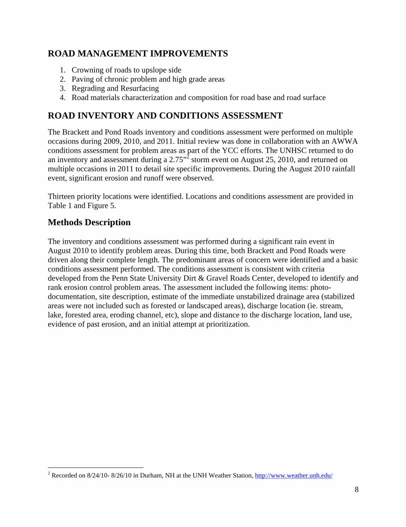
Treatment Strategy Performance Table 3: Treatment Performance of Recommended Strategies for Sediment and Phosphorus
Treatment Strategy TSS Removal Efficiency TP Removal Efficiency ReferenceSediment Basin 50% NA 1Catch Basin 9‐10% NA 2Infiltration Basins 85‐90% 65‐85% 2, 3Stilling Basin 5‐17% NA 4Bioretention 85‐97% 34‐85% 1, 5Infiltration Trenches 85‐90% 60‐85% 2, 3Dry Well 85% 85% 3
Vegetated/grassy swales 30‐90% 29‐43% 6, 7, 9
Porous Pavement* 85% 85% 3*With infiltration bed References include (1) UNHSC, (2) (McCarthy 2008), (3) (DEP 2006), (4) (McLaughlin 2008), (5) (NJDEP 2004), (6) (Storey et al. 2009), (7) (Zhang et al. 2009), (8) (Claytor and Schueler 1996)
Prioritization by Load and Cost
From this, the top 7 locations are identified to account for 79% of the total sediment load (44,000 lbs per year) from the priority locations. These 7 locations are estimated to cost $28,300 in materials for associated improvements. The rankings are listed in Table 4.

26
Table 4: Table of Inventory Ranked by Estimated Sediment Load, Reductions, and Cost
*Costs are planning level estimates of materials only. Labor and equipment are not included.
LocationApprox Road Drainage Area
(ft2)
Estimated annual TSS load
(lbs/yr)
Estimated annual TSS load post tx
(lbs/yr) RE% Cost
#BR004 60,000 10,364 1,178 89% 3,730.00$
#BR005 35,000 9,069 1,284 86% 4,880.00$
#BR002 34,500 8,939 1,016 89% 6,040.00$
#BR007 32,000 8,291 1,174 86% 1,910.00$
#BR011/12 20,000 5,182 990 81% 2,460.00$
#BR013 25,000 4,318 268 94% 6,880.00$
#BR006 24,000 4,146 257 94% 2,440.00$
#BR009 7,100 1,840 260 86% 3,990.00$
#PR002 6,600 1,710 242 86% 3,910.00$
#BR008 6,500 1,684 238 86% 3,930.00$
#BR003 4,400 760 141 81% 1,150.00$
#BR010 3,600 622 88 86% 3,710.00$
#BR001 2,300 397 25 94% 240.00$
Totals 261,000 55,612 6,919 90% $ 45,220.00

27
RECOMMENDED STRATEGIES
This section provides general information on long term maintenance and improvements to unpaved gravel roads. It includes practical tools and details on many of the strategies discussed in the Road Management Plan including ditching, crowning, road surface materials, and other road maintenance practices. It should be used as a general reference when more information is required. The following recommended strategies include 1) Road maintenance, 2) Structural strategies in the form of drainage improvement, and 3) non-structural strategies such as regulations and ordinances, the role and formation of road associations, and preservation of vegetated buffers to protect surface waters.
Road Maintenance
Erosion and Sedimentation Control in Roadside Ditching Practices
Maintenance of roadside conveyance is an essential component of road maintenance. If conveyance of roadside ditches is reduced, erosion and damage to roadways can occur. However, the practice of roadside ditching in the absence of proper stabilization and erosion and sedimentation control can be a significant source of sediment. Erosion and sedimentation control measures should be used where maintenance activities involve ditching, clearing, or excavation resulting in unstabilized soils. A list of recommended practices for road managers and DOT maintenance staff is listed below (AASHTO 2004). Practices focus on ditch, channel, and inlet and outlet protection, and revegetation of disturbed or bare areas, and the use of sedimentation control practices as needed.
• Use temporary vegetation to provide immediate ground cover until permanent landscaping is in place. It is desirable to re-seed and mulch any disturbed areas at the end of the day.
• Other erosion control measures (such as silt fence, check dam, etc.) should be installed prior to commencing work and left in place and maintained until the site is stabilized
• Areas should be re-vegetated with native seed mixes that require minimal care • Temporary structural erosion control measures should be installed when cleaning culverts
or cleaning ditches that discharge into streams, wetlands, lakes or ponds • When cleaning ditches, temporary check dams should be used wherever they are
necessary and placed so that the crest of the downhill dam is at the same elevation of the toe of the uphill dam.
• Check dams should be left in place until the ditch is re-vegetated. • Temporary sediment traps should be placed at the inlet of a culvert that drains into a
stream, wetland or other water body. Sediment traps should be constructed by excavating an additional 1/3 meter (one foot) below the ditch invert for a distance of six meters (20 feet).
• After the project site is stabilized, any accumulated sediment should be removed before removing check dams.

28
• To improve habitat and reduce erosion, consult with the environmental staff regarding incorporation of appropriate soil bioengineering practices, such as live willow cuttings/ stakes/posts and live willow wattles to stabilize disturbed and/or eroding stream banks.
• Sediment control structures should not be placed in streams • The smallest practicable work zone is cleared to minimize erosion • Length and steepness of slopes should be minimized. Place terraces, benches, or ditches
at regular intervals on longer slopes. • Maintain low runoff velocities in channels by lining with vegetation, riprap, or using
check dams at regular intervals, in addition to minimizing steepness and slope length.
Recommended Equipment
The following is a list of recommended equipment for use in road maintenance practices. Descriptions include approximate costs of purchase of equipment. One alternative to purchasing equipment, common for municipalities, is to hire the service out. Many of these services are relatively inexpensive.
Hydro-Seeder The use of a Hydro-seeder is recommended for vegetative stabilization after the maintenance and clearing of roadside ditches. Hydro-seeders are available as truck bed mounted system and tow-behind systems on trailers. These prices vary with respect to the quantity and type of mulches they are capable of spreading. Tow behind systems range from $5,000 - $30,000. Truck bed mounted systems by range from $10,000 - $14,000.
Leaf Removal Equipment The use of a leaf-vacuum is recommended as an alternative to excavation of leaf materials from roadside ditches. The use of an excavator while effective for removal of materials creates unstabilized channels by continually disturbing ditches and not allowing vegetative stabilization. Tow-behind leaf vacuums systems from range from $1,500 - $3,000.
Catch Basin Cleaners The cleaning and removal of sediment from deep sump catch basins will need to occur routinely. Vactor trucks costs are on par with typical large vehicles. Costs for vactor trucks begin at $125,000 and range upwards. Alternatively, catch basin cleaning is commonly hired out, and can be completed typically around $50-100 per catch basin.
Road Materials
This section excerpted from the York County Soil and Water Conservation District publication on Camp Roads (2007). There are three basic types of soil: gravel, sand, and fines (listed in order from largest to smallest particle size). Gravel and sand particles are readily distinguishable to the naked eye. Fines (silts and clays) are generally comprised of particles too small for the eye see. Each soil type has specific properties that make it best for different aspects of road building. Gravel is very durable and drains freely. Sand also drains efficiently. Fines pack and bind well and they help shed water, because they do not drain well (YCSWCD 2007).

Road bas
• S• 0 • T• R
Road sur
• A• 7 • T
Crownin
This secton Camp Road crosurface. Troad. Eiththe road. of the roawill creatvehicle sgood roamaking iprovide adrainage
Grading grader wused piec
se material s
omewhat coto 7 percent
The base layeRoad surface
rface materia
A maximum pto 12 percen
The surface la
ng and Gra
tion excerptep Roads (200
owning and gTo crown a rher side of thCrowning i
ad surface. Ate potholes oplashes throd surface. Stt susceptiblea safer surfac(YCSWCD
is the procesith a steel cuce of equipm
hould be:
oarser than tht fines (this per should be material nee
als should be
particle sizent fines (to payer should
ading
ed from the Y07).
grading are troad means this high poins the quicke
An insufficieor erode the ugh them, retanding watee to tire ruttince for travel2007).
Figu
ss of smoothutting blade t
ment for gene
he road surfapromotes sub18 inches oreds to pack w
e:
of 2 inches pack well anbe about 4 to
York County
the primary mto create a hnt is sloped gst way to ge
ent crown wiroad surfaceesulting in ther will also sng. Proper g. Figure 20 b
ure 20: Crown
hing and crowto redistribueral camp ro
ace material bsurface drar thicker. well, be dura
(for a smootd shed watero 6 inches th
Soil and Wa
means by whhigh point thagently away t water off thill allow wate. The pothohe loss of finseep into thegrading will pelow shows
n profile (YCS
wning a gravute soil materad maintena
(3”-4” maxiainage).
able, and she
th ride) andr). hick.
Water Conserv
hich surfaceat runs lengt from the cehe road, prevter to puddleles will cont
ne clay partice roadbed, wprevent pothhow crowni
SWCD 2007).
vel road. Thirial. The gra
ance. It can b
imum partic
ed water.
vation Distri
e water is drathwise alongenter toward venting sign
e on the roadtinue to growcles that are
weakening theholes from foing promote
is practice inader is the mbe very versa
cle size); and
ict publicati
ained off theg the center othe outer ed
nificant erosid surface; thiw each time necessary fo
e road and orming and s surface wa
nvolves usinmost frequent
atile when u
29
d
on
e road of the dge of ion is a
for a
ater
ng a tly used

by an exproad matvehicle trcan drainThis probrain. Alwthe gradiedge of th
F
Dust Co
This secton Camp Dusty comoisture which arethat holdgravel, w
Chemica
This sectManual ( A chemicadded to from its o All graveserve a logravel romoisture
perienced operial that haraffic. Thesen off the roadblem has the
ways make sung blade. Ushe road, and
igure 21: Sand
ontrol Strat
tion excerptep Roads (200
onditions occloss which,
e essential ind the road surwhich advers
ally Treated
tion is an exc(2010).
cally treatedit recently e
original, untr
el roads will ow volume o
oad produces, the problem
perator. Regus either beene little ridgesd (Figure 21e potential toure that watesually, camp
d pulling it b
d and vegetati
tegies
ed from the Y07).
cur when a roin turn, loos
n maintaininrface materiaely affects tr
d Roads
cerpt from th
d unsealed roenough to binreated state
give off dusof traffic, ands varies greatm is greatly r
ular grading n washed to ts will defeat ), and chann
o cause severer can get ofp roads are reack into the
ion build-up p
York County
oad surface hsens and wea
ng the integrial in a tight, raction and c
he Wyoming
oad has had dnd together o(Wyoming T
st under traffd dust is usutly. In areas reduced. Ari
is an effectithe road edgthe purpose
neling it alonre damage toff the road byegraded by scenter (YCS
prevents drain
Soil and Wa
has dried ouakens the roity of a gravhard mass. T
can result in
Technology
dust suppresor significanTechnology
fic. After allually an inheof the countid or semi-ar
ive means ofge or has beee of crowningng the outer eo a road surfy smoothingscraping thisSWCD 2007
nage to sides o
Water Conserv
ut. Soil fines ad surface ael road surfaThe fewer therosion (YC
y Transfer G
sant (other tntly alter the Transfer Ce
l, they are unerent problemtry that receirid regions s
f redistributien pushed tog by catchinedge of the rface during pg the edge ofs material fro7).
of road(YCSW
vation Distri
can actuallyand cause a loace. Soil finehe fines, the CSWCD 200
Gravel Roads
than water) oroad’s surfa
enter 2010).
npaved roadsm. The amouive a high amsuch as the d
ing ridges ofo the edge byng water beforoad surfaceperiods of hef the road wiom the outer
WCD 2007).
ict publicati
y shrink due oss of soil fies are the binlooser the
07).
s Manageme
or soil stabilacing materi
s that typicaunt of dust thmount of desert southw
30
f y ore it .
eavy th r
on
to ines, nders
ent
izer al
lly hat a
west

and muchregions athese areof gravelwhile sombinding cthere wilmake. Viif traffic than pay maintenaa good eccontinue informati Reclaimeit is moreuse of thialso effecasphalt in2007).
Structu
Sedimen
A sedimeexcavatin(McCarth
h of the greaaround the glas if there arl also has somme glacial decharacteristicl be dust! Wirtually all mvolume is lofor itself wi
ance. At this conomic decto increase i
ion on makin
ed pavemente granular anis material isctive on othen this materi
ural Strate
nt basins an
ent basin is ang a natural hy 2008).
at plains regilobe can havre residencesme effect oneposits of grc that will re
Whether to prmethods of duow. On the oth the benefpoint, many
cision in the in the futureng this decis
t is old pavemnd darker bes on steep roer high stresial acts as a b
egies
Figu
nd Ditch Tu
a water impodepression.
ion in the USve similar wes located nea
n the amountravel with a pesist dusting ovide some ust control r
other hand, iffits of reducey agencies wlong run, es
e. However, nsion in Appe
ment that hacause of the
oad segmentss areas suchbinder, whic
ure 22: Ditch T
urnouts
oundment cr Sediment se
SA are proneeather patterar the road at of dust. Somportion of hiremarkably type of dust equire annuaf traffic is hied material lo
will face prespecially if thnever pave a
endix D (USD
as been grounresidual asp
s that have has sharp tur
ch makes it m
Turnout (Main
reated by conettles out wh
e to long perrns. Dust canand traffic is me limestonighly plasticwell. Still, i
t control or nal treatment.igh, the cost oss and redusure to pavehere is good a road beforeDOT 2000).
nd up. It loophalt. The mhad problemsrns and intermore resistan
neDEP 2010).
nstructing anhile the runo
riods of dry wn really bringhigh. The q
ne gravels canc clay can takin prolongednot can be a h. The cost caof dust cont
uced need foe the road. It
indication the it is ready!.
oks similar tomost common
s with surfacrsections. Thnt to erosion
.
n embankmeoff is stored i
weather. Simg complaints
quality and tyn dust severke on a strond dry weathehard decisioan be prohibtrol can mor
or blade may actuallhat traffic w! There is go
o road graven and effectivce erosion. I
he residual n (YCSWCD
ent or by in the basin
31
milar s in ype rely ng er, on to itive e
ly be will ood
el, but ve t is
D

Fig The Lakeone showsuspensiocapable oand dewa Ditch Tuspreaders2008).
Deep Su
Deep sumencouragthat are pinlet or abelow thebasins caperforma
gure 23: Sedim
e George Rewn in Figure on and be stoof having theatering techn
urnouts divers that conver
ump Catch
mp catch basge sediment tpart of a stora grated opene outlet. Sed
an be used inance. Hooded
ment Basin loc
eservoir and 23 to slow t
ored in a base stored sediniques (Distr
rt the stormwrt the ditch f
Basins
sins are simito settle out rm drain or pning on top odiment removn combinatiod outlets are
ated at Upper
Sediment Bathe stream vesin prior to itiment be remrict 2007).
water runoff flow into she
lar to sedimeof runoff du
piping systemof the systemval is best w
on with hood described in
r Hague Brook
asin Cleanouelocity encot reaching L
moved on a r
in a roadsideeet flow that
ent basins inuring storm em. Sedimentm (LGA). Dewhen configuded outlets ton greater det
k in the Lake
ut Program uuraging sedi
Lake George.regular basis
e ditch into adistributes a
n that their pevents. Catct enters a cateep sumps arured in an ofo improve setail below.
George water
uses sedimeniment to dro. These basi with excava
a series of chacross a buff
primary functch basins aretch basin thrre typically 4ffline configuediment rem
rshed (LGA).
nt basins likop out of ins are then ation equipm
heck dams afer (McCarth
tion is to e precast systrough either 4 feet deep uration. Catc
moval
32
e the
ment
and hy
tems an
ch

Catch baGeorge ALake GeoGeorge Astormwatfrom the sediment
Hooded
While cabasins arto additiofurther trpollutantthe remoefficiencybasins, wtype of hreported 2007).
sins have beAssociation iorge project Association, ter to enter tbasin. If the
t is reduced o
Outlets an
atch basins arre not suited onal Stormwreatment duet reductions. val of oil, gry of the catc
while others mhooded outlet
to achieve T
een successfuin at Lake Gis shown in requires schhe basin. Ade excess sedor removed c
d Catch Ba
re prevalent for efficient
water BMPs (e to monetary Hooded Ou
rease, trash, ch basin. Sommay require t retrofit, is d
TSS reductio
Figure 24:
ully used as George in New
Figure 24. heduled cleardditional madiment is notcompletely.
asin Inserts
throughout t pollutant an(EPA 2006ay or space coutlets/Insertsdebris, sedim
me inserts arretrofit cons
designed to on by 56% an
Catch Basin (
a roadside sw York. AnCatch basin ring of debri
aintenance isremoved th
s
the drainagend sediment a). Since theonstrictions s are designement and othre designed tstruction thefit cylindricand TP reduct
(LGA).
stormwater mn example of
maintenancis in and aro required to
he ability of t
e systems wiremoval and
ere is not alwretrofits can
ed to assist dher floatableto drop direce (EPA 2006al or round stion by 46%
managementf a catch basce, as describound the basi
remove trapthe system to
ithin the Unid are ideally
ways the optin help achievdeep sump caes by improvctly into an e6a). The Roustructures an
% (BMP 2011
t tool by the sin used in thbed by the Lin to allow pped sedimeno settle out
ites States, my a pretreatmion to have ve higher atch basins wving the remoexisting catcund Snout®,nd has been 1b; Lambert
33
Lake he
Lake
nt
many ment
with oval h , a

Infiltrat
Infiltratiotemporaror a portithe storag
Figure 25: T
tion Basins
on basins arerily store runion of an evege capacity o
Typical Instal
e located eithnoff from stoent. In someof the basin
llation of a hoo
her on the suorm evens. Ie cases basin(McCarthy 2
oded outlet (R
urface or belInfiltration bns are design2008).
Round Snout S
low ground abasins may bned to release
Shown) (BMP
and are desigbe capable ofe stormwate
P 2011a)
gned to f infiltrating er that exceed
34
all ds
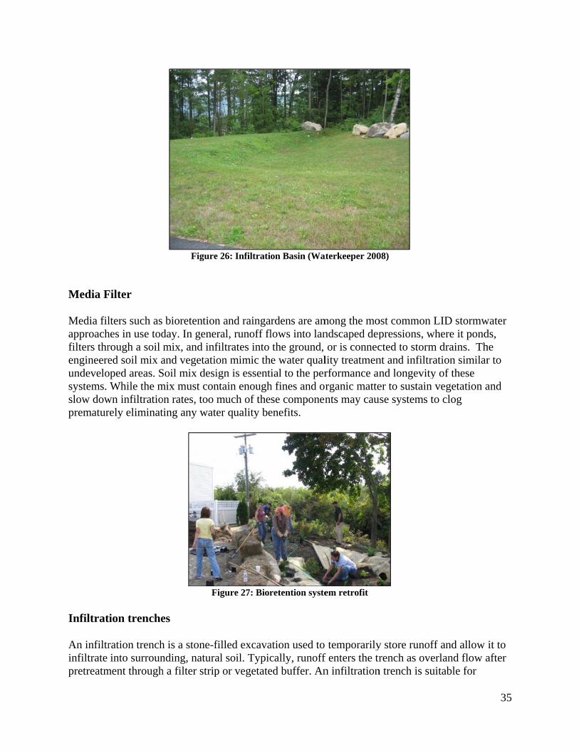
Media F
Media filapproachfilters threngineereundevelosystems. slow dowprematur
Infiltrat
An infiltrinfiltrate pretreatm
Filter
lters such ashes in use todrough a soil ed soil mix a
oped areas. SWhile the m
wn infiltratiorely eliminat
tion trenche
ration trenchinto surroun
ment through
Figure
bioretentionday. In genermix, and infand vegetatioSoil mix desimix must conon rates, too mting any wate
F
es
h is a stone-fnding, naturah a filter strip
e 26: Infiltratio
n and raingaral, runoff flfiltrates into on mimic thign is essentintain enoughmuch of theer quality be
Figure 27: Bior
filled excavaal soil. Typicp or vegetate
on Basin (Wa
rdens are amlows into lanthe ground, e water qualial to the per
h fines and ose componen
enefits.
retention syste
ation used tocally, runoffed buffer. An
aterkeeper 200
mong the mondscaped depor is connec
lity treatmenrformance anrganic mattents may cau
em retrofit
temporarilyf enters the trn infiltration
08)
ost common pressions, wcted to stormnt and infiltrand longevityer to sustain
use systems t
y store runofrench as ove
n trench is su
LID stormwwhere it pondm drains. Thation similary of these vegetation a
to clog
ff and allow erland flow auitable for
35
water ds, he r to
and
it to after

treating rof parkin
Dry Wel
A dry wecaptured the stormmaintena
runoff from sng lots, betw
ll
ell is a cylindstormwater
mwater. The ance to be re
small drainaeen resident
Figu
Figure 2
drical undergto infiltrate debris and smoved (LGA
age areas (lestial lots, and
ure 28: Infiltr
29: Infiltration
ground pre-cin the grounsediment wilA 2011).
ss than 10 acalong roads
ation Trench
n Trench (Wa
cast system wnd white retall remain in
cres). Install are most co
(Akan 2002).
aterkeeper 200
with perforaaining the dethe well and
ations arounommon (McC
08).
ated sides thaebris and sedd will require
nd the perimeCarthy 2008
at allows diment carriee periodic
36
eter 8).
ed by

F
Road Cr
Culvert CCulverts embankmterrestriainto vegeinstalled directed uCulverts ways undconveyanand debriprovides
Figure 30: Dry
rossing and
Crossings are conduits
ment. Properal species. Oetated bufferwhen: a streunder the rotransport str
derneath roance for wateris that are traexamples of
y Well (LGA)
d Conveyan
s that conveyrly designed
Other culvertr areas capabeam, brook, ad. This keereamflow, sedways. Wher ways, but aansported wf culvert typ
nce
y streamflowand construcs transportin
ble of handlinseasonal run
eps the road feasonal or sten possible calso as an efithin these wes and when
Figu
w, sediment, cted culverts
ng groundwang the water
noff channel,from disruptorm event reculverts shouffective methwater ways(Mn each type i
ure 31: Dry W
and debris ts also enableater or runoffr without ero, or subsurfating the natuelated runoffuld be desighod to conveMaineDEP 2is applicable
Well (Waterkee
through a roae the passageff should dispoding Culverace drainage ural drainageff, and subsurgned as not oey the aquati2010; USFS e.
eper 2008).
adway e of aquatic perse the warts should beway must b
e system rface drainag
only a methoic life, sedim2005). Tabl
37
and ater e be
ge od of ment
le 5
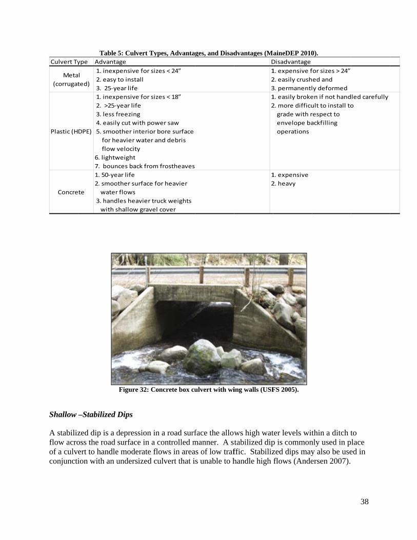
Culvert Ty
Meta(corrugat
Plastic (H
Concre
Shallow A stabilizflow acroof a culvconjuncti
Table ype Advanta
l ted)
1. inexp 2. easy 3. 25‐y
DPE)
1. inexp 2. >25‐y 3. less f 4. easily 5. smoo for he flow v6. lightw7. boun
te
1. 50‐ye2. smoo water 3. hand with s
–Stabilized
zed dip is a doss the road ert to handleion with an u
5: Culvert Tyage pensive for sizto installear lifepensive for sizyear lifefreezingy cut with powother interior eavier water avelocityweightnces back fromear lifeother surface fr flowsdles heavier trshallow grave
Figure 32: Co
Dips
depression insurface in a
e moderate fundersized c
ypes, Advanta
zes < 24”
zes < 18”
wer sawbore surfaceand debris
m frostheaves
for heavier
ruck weightsl cover
oncrete box cu
n a road surfcontrolled m
flows in areaculvert that i
ges, and Disad
ulvert with wi
face the allowmanner. A sas of low trafs unable to h
dvantages (MD12312
12
ing walls (USF
ws high wattabilized dipffic. Stabilizhandle high
aineDEP 2010Disadvantage1. expensive f2. easily crush3. permanentl1. easily broke2. more difficu grade with r envelope ba operations
1. expensive2. heavy
FS 2005).
ter levels witp is commonzed dips mayflows (Ande
0).
for sizes > 24”ed andly deformeden if not handult to install torespect toackfilling
thin a ditch tnly used in py also be useersen 2007).
38
led carefullyo
to lace
ed in

Rubber R Rubber rwhile lett(Anderse
Energy D
Energy dExamplescour hol(Olsson E
Razors
razors are rubting vehicles
en 2007; Ma
Dissipaters
dissipaters ars of various les, stilling bEnvironmen
bber strips ths pass. ThesineDEP 200
Figu
s
re designed ttypes of ene
basins, ripraptal Sciences
hat protrude se structures 06).
ure 33: Rubbe
to reduce waergy dissipatp, vegetated 2004; USFS
above the roshould not b
r Razor (Main
ater velocity ters are interditches, deb
S 2005).
oad surface tbe used on r
neDEP 2006).
and preventrnal and extebris racks an
to intercept roads that are
.
t erosion witernal dissipatnd concrete o
and divert we plowed
thin a water ters, natural
or steel baffle
39
water
way.
es

Non-St
Vegetate
Vegetatesheet flowvelocities2008b). Vegetateare not nprovide autilizing vegetatiosedimentcontains velocities
ructural S
ed Buffers
d filter stripw from adjacs allowing w
d buffers alsecessarily ana physical banatural vege
on that mimitation due tolitter and des encouragin
Figure 34: D
Strategies
and Filter S
s, are graduacent impervi
water to infilt
so reduce shn engineeredarrier betweeetation (ie. focs undisturb established
ebris which ing infiltration
ebris rack we
Strips
ally sloped vious areas. Ttrate as sedim
eet flow velod or construcen a body oforest, shrubb
bed forest. Uvegetation cncrease surfn and a redu
ll upstream of
vegetated areThese vegetament settles
ocities but thcted system. f water and aby uplands, oUndisturbed fcover. In adface roughneuction in eros
f culvert (USF
eas that are dated areas fu(Horsley W
hey differ fro A buffers p
adjacent landor floodplainforest has m
ddition to vegess further resion (Grace
FS 2005).
designed to runction by re
Witten Group
om filter striprimary funcd use. This ins) or purpos
minimal erosigetation, theeducing surfaIII 2002).
receive runoeducing runo2010; McCa
ips in that thction is to is achieved bsefully plantion and e forest floorface flow
40
off as off arthy
hey
by ted
r

Improve
Planningconfined plans. Inregulatiowatershewater resa vision fparcel-byinfrastrucupdating today. Onplanning developmincludes incorpora
Figur
ed Regulati
g for better stto municipa
n addition, thns or zoningd) set the gr
sources. Whfor the commy-parcel decicture, and mlocal regula
ne of the moboard’s site
ment of a sepmany systemate some for
re 35: Filter S
ions and Or
tormwater mal boundariehe visions sug. Sound plaroundwork fohile most community, manyisions can ha
municipal budations and deost applicable plan reviewparate stormwms capable orm of filtratio
trip Plan and
rdinances
management s and waters
upported by manning shoulor sound polmmunities hy land use dave cumulatidgets. A groeveloping gue methods is
w regulationswater ordinaof advanced on and/or inf
Profile View
is challenginshed plans armaster plansld help commlicies and ultave a master
decisions are ive impacts
owing trend iuidelines to rs updating sts. Updated sance typicallstormwater filtration. D
(Claytor and
ng because wre not always are not alwmunities (antimately bettr plan or commade on a pon water resis emerging reflect the hitormwater mstormwater rly reflect s a managemen
Development
Schueler 1996
water resourys integrated ways implemnd their neighter protectiomprehensiveparcel-by-pasources, storwhere muni
igher treatmemanagement regulations oBMP toolbo
nt. These syst of improve
6)
ces are not into master ented throughbors withinn of valuabl
e plans outlinarcel basis. Trmwater icipalities arent standardstandards in
or the ox which nostems often d regulation
41
gh n the le ning These
re ds of n the
ow
ns

42
will mean that new developers will be part of the solution in building the necessary infrastructure that protects water resources and ultimately decreases municipal expenses saving taxpayers money.
Formation of a Road Association
A guide created by the York County Soil and Water Conservation District (SWCD) with assistance from the Maine Department of Environmental Protection to assist with the formation of road associations can be found at (http://www.maine.gov/dep/blwq/docwatershed/road_association_guide.pdf) (SWCD 2009). The document cites a $1 spent in routine maintenance will save $15 in capital repairs. Reasons listed for the development of a Road Association are:
1. Improve road safety and drivability. 2. Reduce maintenance costs over time. 3. Provide liability protection for association members. 4. Sustain the clarity and quality of your lake’s water. 5. Protect the value of your lakefront property investment.
GENERAL CHARACTERIZATION OF LAND-USE WITHIN WATERSHED
Un-Improved Gravel and Low-Volume Roads
Predominant Land Cover: Unstabilized roads, and roadside drainage Description:
Table 6: Predominant Pollutant Sources for Un-Improved Gravel and Low-Volume Roads
Pollutant Pollutant Sources Reference
Petroleum HydrocarbonsAntifreeze and Hydraulic Fluids
1
Lead and Heavy Metals Gasoline Additives 2
OrganicsDiesel and Polycyclic
Aromatic Hydrocarbons (PAH's)
1
CopperDe‐icing salts
containing chlorides1
NaCl De‐icing agents 3
Salts, Petroleum‐based organics, Synthetic polymer, Electrochemical product, Clay additives
Dust Suppresant 4
References include (1) (The Low Impact Development Center et al.), (2) (Lagerwer and Specht 1970), (3) (Forman and Alexander 1998), (4) (Piechota et al. 2002).

43
Table 7: Predominant Pollutant Concentrations for Un-Improved Gravel and Low-Volume Roads Source Area Unit TSS mg/L TP mg/L Reference
Unimproved Poorly Maintained Gravel Surface3198 (Abs Range 6.0‐
71,600)NA 1
Gravel Road 197‐885 0.23‐0.99 2Transportation/Communication/Utility Runoff 100 0.2 3
References include (1), (Clinton and Vose 2003), (2) (Sheridan and Noske 2007), (3) (Hagen and Walker 2006).
Residential
Predominant Land Cover: Rooftops, driveways, roads, and lawns Residential land uses range from high density, represented by the multiple unit structures of urban cores, to low density, where houses are on lots of more than an acre, on the periphery of urban expansion. Linear residential developments along transportation routes extending outward from urban areas should be included as residential appendages to urban centers.3
Table 8: Predominant Pollutant Sources for Residential Land-Use
Pollutant Pollutant Sources Gross Solids, Sediment, and Floatables
Streets, lawns, driveways, roads
Pesticides and Herbicides
Residential lawns and gardens, roadsides, utility right-of-ways, soil wash-off
Organic Materials/Oxygen Demanding Substances
Residential lawns and gardens, animal wastes
Metals Automobiles, soil erosion Oil and Grease/ Organics Associated with Petroleum
Roads, driveways, illicit dumping to storm drains
Bacteria and Viruses Lawns, roads, soil erosion, leaky sanitary sewer lines, animal waste, septic systems
Nitrogen, Phosphorus, and Other Nutrients
Lawn fertilizers, animal waste
Source: U.S. EPA 1999 (Preliminary Data Summary of Urban Storm Water BMPs).
Table 9: Predominant Pollutant Concentrations for Residential Land-Use Source Area Unit TSS mg/L TP mg/L Residential (General) 4 100 .40 Med. Density Residential 5 85 .52 Residential Roof 19 .11 Residential Street 172 .55 Driveway 173 .56 2 Caraco (2001) , default values averaged from several individual assessments; 3 Camp, Dresser, and McKee,
Merrimack River Watershed Assessment Study, Draft Screening Level Model, January 2004
3 James R. Anderson, Ernest E. Hardy, John T. Roach, And Richard E. Witmer, “A Land Use and Land Cover Classification System for Use with Remote Sensor Data,” Geological Survey Professional Paper 964 (1976)

44
REFERENCES
Akan, A. O. (2002). "Sizing stormwater infiltration structures." Journal of Hydraulic Engineering-Asce, 128(5), 534-537.
Andersen, D. C. (2007). "Road Impacts on the Baca National Wildlife Refuge, Colorado, with Emphasis on Effects to Surface- and Shallow Ground-Water Hydrology—A Literature Review." U.S. Fish and Wildlife Service, Reston, Virginia.
Acton Wakefield Watershed Alliance (AWWA). (2010). The Youth Conservation Corp 2010 Season Report.
Acton Wakefield Watershed Alliance (AWWA), and FB Environmental. (2010). "Salmon Falls Headwaters Lakes Watershed Management Plan."
AASHTO (2004).NCHRP Project 25-25 (04) Environmental Stewardship Practices, Procedures, and Policies for Highway Construction and Maintenance. 2004, American Association of State Highway and Transportation Officials (AASHTO), Center for Environmental Excellence. Chapter 10 Roadside Management and Maintenance: Beyond Vegetation, Section 10:12 Erosion and Sediment Control in Maintenance.
Claytor, R. A., and Schueler, T. R. (1996). "Design of Stormwater Filtering Systems." The Center for Watershed Protection, Ellicott City,, MD.
Clinton, B. D., and Vose, J. M. (2003). "Differences in surface water quality draining four road surface types in the Southern Appalachians." Southern Journal of Applied Forestry, 27(2), 100-106.
DEP, D. O. E. P. B. o. W. M. (2006). "Pennsylvania Stormwater Best Management Practices Manual." DEPARTMENT OF ENVIRONMENTAL PROTECTION
Bureau of Watershed Management. District, W. C. S. a. W. C. (2007). "Lake George Basin Reservoir and Sediment Basin Cleanout Program." Waren County Soil and Water Conservation District Lake George Reservoir and Sediment Basin Cleanout Program, Warrensburg, NY. Durham, T. o. "SITE PLAN REVIEW REGULATIONS of DURHAM, NEW HAMPSHIRE."
Town of Durham, Durham, NH. EPA, E. P. A. (2009a). "Detroit River-Western Lake Erie Basin Indicator Project."
Environmental Protection Agency Large Lakes and Rivers Forecasting Research Branch. EPA, E. P. A. (2006a). "Catch Basin Inserts." National Pollutant Discharge Elimination System
(NPDES). EPA, U. S. E. P. A. (2006b). "Infiltration Basin." National Pollutant Discharge Elimination
System (NPDES). EPA, U. S. E. P. A. (2009b). "Glossary & Acronyms." EPA. Forman, R. T. T., and Alexander, L. E. (1998). "Roads and their major ecological effects."
Annual Review of Ecology and Systematics, 29, 207-+. Grace, J. M. (2002). "Effectiveness of vegetation in erosion control from forest road sideslopes."
Transactions of the ASAE, American Society of Agricultural Engineers, 45(3). Hagen, J., and Walker, F. (2006). "Oostanaula Creek Watershed Nonpoint Source Pollution
Inventory and Pollutant Load Estimates." University of Tennessee Extension – Biosystems Engineering and Soil Science, Knoxville, TN.
York County Soil and Water Conservation District. (2007). "Camp Road Maintenance Manual." 58pp.
45
Lagerwer, J., and Specht, A. W. (1970). "Contamination of Roadside Soil and Vegetation with Cadmium, Nickel, Lead, and Zinc." Environmental Science & Technology, 4(7), 583-&.
Lambert, M. (2007). M. T. J. Mullen, ed., Lyme, Connecticut. LGA, L. G. A. "Reservoirs and Sediment Basins." LGA, L. G. A. "Reservoirs and Sediment Basins." LGA, L. G. A. (2011). "Stormwater Management Projects: Catch Basins and Dry Wells." Lake
George Association. MEDEP, M. D. o. E. P. (2006). "Conservation Practices for Homeowners Factsheet Series."
Maine Department of Environmenal Protection (Maine DEP). MEDEP, S. o. M. D. o. E. P. (2010). "Gravel Road Maintenance Manual: Guide For
Landownders on Camp and Other Gravel Roads." Maine Department of Environmental Protection Bureau of Land and Water Quality, Kennebec County Soil and Water Conservation District.
McCarthy, J. (2008). "NEW HAMPSHIRE STORMWATER MANUAL: VOLUME 1 Stormwater and Antidegradation." New Hampshire Department of
Environmental Services. McLaughlin, R. A. (2008). "Stilling Basin Design and Operation for Water Quality: Field
Testing." Soil Science Department, North Carolina State University, Raleigh, NC. NJDEP, N. J. D. o. E. P. D. o. W. M. (2004). "New Jersey Stormwater Best Management
Practices Manual: Chapter 4." New Jersey Department of Environmental Protection Division of Watershed Management, Trenton, N.
NPDES, N. P. D. E. S. (2004). "NPDES Glossary." EPA. NPDES, N. P. D. E. S. (2011). "Stormwater Program." Environmental Protection Agency (EPA). Olsson Environmental Sciences, W. W. E., Inc. (2004). "Drainage Criteria Manual." City of Lincoln Public Works and Utilities Department and the Lower Platte South
Natural Resources District, Lincoln, NE. Piechota, T., Ee, J. v., Batista, J., Stave, K., and James, D. (2002). "Potential Environmental
Impacts of Dust Suppressants: “Avoiding Another Times Beach”." Las Vegas, Nevada. Riedel, M. S. (2003). "Collaborative research and watershed management for optimization of
forest road best management practices." UC Davis: Road Ecology Center. Scheetz, D. B. E., and Bloser, S. M. (2008). "Environmentally Sensitive Maintenance Practices
for Unpaved Roads: Sediment Reduction Study." Center for Dirt and Gravel Road Studies The Pennsylvania State University, Harrisburg, PA.
Sheridan, G. J., and Noske, P. J. (2007). "Catchment-scale contribution of forest roads to stream exports of sediment, phosphorus and nitrogen." Hydrological Processes, 21(23), 3107-3122.
Storey, B., Li, M., McFalls, J., and Yi, Y. (2009). "STORMWATER TREATMENT WITH VEGETATED BUFFERS." Texas Transportation Institute The Texas A&M University System,
College Station Texas. CFDGR (2009). "Overview of Pennsylvania's Dirt and Gravel Road Maintenance Program." The
Center for Dirt and Gravel Road Studies (CFDGR), The Pennsylvania State University. SWCD (2009). "A Guide to Forming Road Assoctiations." York County Soil and Water
Conservation District (SWCD), Maine Department of Environmental Protection. The Low Impact Development Center, I., Consultants, G., Florida, U. o., and University, O. S.
"EVALUATION OF BEST MANAGEMENT PRACTICES FOR HIGHWAY RUNOFF CONTROL Appendices To User’s Guide for BMP/LID Selection (Guidelines Manual)."

46
National Cooperative Highway Research Program, Transportation Research Board, National Research Council.
USDOT, U. S. D. O. T. (2000). " Gravel Roads Maintenance and Design Manual." South Dakota Local Transportation Assistance Program.
USFS, U. S. F. S. T. a. D. C. (2005). "RIPARIAN RESTORATION: Roads Field Guide." United States Department of Agriculture (USDA)
U.S. Department of Transportation. Van Lear, D. H., Taylor, G. B., and Hanson, W. F. (1995). "Sedimentation in the Chattooga
River Watershed." Clemson Univeristy, Department of Forest Resources. Waterkeeper, L. G. "State of the Lake Stormwater Management." Lake George Watershed
Conference, 24. Wyoming_Technology_Transfer_Center. (2010). "Volume 1: Gravel Roads Management."
State of Wyoming Department of Transportation/ U.S. Department of Transportation Federal Highway Administration, Laramie, Wyoming.
Zhang, R., Zhou, W. B., Field, R., Tafuri, A., Yu, S. L., and Jin, K. L. (2009). "Field test of best management practice pollutant removal efficiencies in Shenzhen, China." Frontiers of Environmental Science & Engineering in China, 3(3), 354-363.

47
APPENDIX A: TERMINOLOGY
Best Management Practices (BMP's): Methods and means that have been determined to be the most effective, practical approaches of preventing or reducing pollution and detrimental impacts from stormwater runoff (Durham). Buffer: A vegetated area or zone separating a development from a sensitive resource or neighboring property in which proposed development is restricted or prohibited (Durham). Impervious Surfaces: A material with low permeability that impedes the natural infiltration of moisture into the ground so that the majority of the precipitation that falls on the surface runs off or is not absorbed into the ground. Common impervious surfaces include, but are not limited to, roofs, concrete or bituminous paving such as sidewalks, patios, driveways, roads, parking spaces or lots, and storage areas, compacted gravel including drives and parking areas, oiled or compacted earthen materials, stone, concrete or composite pavers, wood, and swimming pools (Durham). Polycyclic Aromatic Hydrocarbons (PAHss): PAH’s are “a group of organic chemicals that includes several petroleum products and their derivatives” (EPA 2009b). Pollutant: A pollutant is a substance that adversely affects the usefulness of a resource and is in a form that can be incorporated into, or be ingested by organisms within, the environment (EPA 2009b). Chlorides: Chloride is a salt compound resulting from the combination of the gas chlorine and a metal. Common chlorides include sodium chloride (NaCl) and magnesium chloride (MgCl2) (EPA 2009a). Unimproved Road: An unimproved road is a gravel or low use road that does not contain drainage features (Wyoming_Technology_Transfer_Center 2010). Runoff: Stormwater runoff is the generated when precipitation from rain and snowmelt events flows over impervious surfaces (NPDES 2011). Sediment: Sediment is a collection of loose particles that settle at the bottom of a body of water. Sediment is generated from the erosion of soil or from the decomposition of plants and animals(EPA 2009b). Sheet Flow: Sheet flow is a shallow lateral flow traveling across an impervious surface. Total Suspended Solids (TSS): TSS is a “measure of the filterable solids present in a sample, as determined by the method specified in 40 CFR Part 136” (NPDES 2004). Gravel Roads Management Systems (GRMS): When referring to management systems, historically such systems have been referred to as ‘gravel roads management systems’ or ‘gravel roads maintenance systems.’ In keeping with this precedent, the term ‘gravel roads management or maintenance system’ (GRMS) is used to refer to systems designed to plan and program

48
unsealed roads maintenance and improvement processes (Wyoming_Technology_Transfer_Center 2010). Drainage Terms: When a road is more than simply tracks in the surrounding countryside made by four (or more) wheeled vehicles one should describe it as ‘formed’ or ‘improved.’ To some, an ‘improved’ road merely has ditches and other drainage features, while to others, an ‘improved’ road also has imported surfacing aggregate (Wyoming_Technology_Transfer_Center 2010). Dirt Roads: Use of this term by roads professionals is discouraged, though it is popular with the general public. Though sometimes synonymous with the term ‘earth roads’ below, the term ‘dirt roads’ should not be used due to its multiple meanings (Wyoming_Technology_Transfer_Center 2010). Earth or Native Soil Roads: This term should be used to describe roads surfaced with soil from the immediate vicinity. To some, even a road that has material pulled up from the borrow pit to form the road is no longer an ‘earth’ road. When using these terms, care should be taken to indicate whether or not the native soil has been moved from its original location to the road (Wyoming_Technology_Transfer_Center 2010). Gravel Roads: This term is problematic due to its widespread use with multiple meanings. To some, a ‘gravel’ road implies crushed alluvial rock while to others it simply implies that surfacing material has been imported. Roads made with a crushed shale surface may be called a ‘shale road’ or they may be simply known as a ‘gravel road;’ the situation is similar for other roads surfaced with a particular type of crushed or processed aggregate. Given these ambiguities, this term should be used with caution, and when it is used, it should be concisely defined. Chemically Treated Roads: A chemically treated unsealed road has had dust suppressant (other than water) or soil stabilizer added to it recently enough to bind together or significantly alter the road’s surfacing material from its original, untreated state (Wyoming_Technology_Transfer_Center 2010). Surface Treated Roads: Roads comprised of aggregate topped with a sealant, typically asphalt, cutback asphalt or emulsified asphalt, are referred to as ‘surface treated roads.’ They may also be referred to as ‘bituminous surface treated’ or ‘BST’ roads. When a layer of aggregate chips is placed on top of the asphalt, the road may be referred to as a ‘blotter road’ or a ‘chip seal road.’ When no chips are added, the road may be referred to as an ‘inverted penetration’ (‘invert pen’) road. Other terms referring to various surface treatments include ‘armoring,’ ‘armouring,’ ‘metalling’ and ‘running course.’ These terms are not in widespread use and their use is discouraged. If they are used, they should be concisely defined (Wyoming_Technology_Transfer_Center 2010). Paved Roads: The use of the terms ‘paved’ and ‘unpaved’ is discouraged because they have such widely disparate meanings to different people and in different parts of the world. To some, any road with constructed layer(s) to carry traffic is considered a pavement, while in other places any road with a semi-permanent surface is ‘paved,’ while to still others, the term ‘pavement’ implies

49
that the road is constructed with hydraulic or asphaltic concrete and is placed with a screed (Wyoming_Technology_Transfer_Center 2010). Sealed Roads: When a road’s surface is semi-permanent and water-resistant, the road is said to be ‘sealed.’ ‘Unsealed’ roads are those with a granular surface that are or may be maintained on a routine basis with a motor grader, and are the road types whose repair and maintenance is the topic of this paper (Wyoming_Technology_Transfer_Center 2010). Porous Media: Material with open connected pore spaces that allows water to percolate through it such as granular soils, gravel, crushed stone, pervious pavements, and woven and non-woven geosynthetics (Durham). Redevelopment: Any man-made change to previously improved real estate, including but not limited to buildings or other structures, mining, dredging, filling, grading, paving, excavation, and drilling operations (Durham). Riparian: Referring to anything connected or immediately adjacent to the shoreline or bank of a stream, river, pond, lake, bay, estuary or other similar body of water (Durham). Riparian buffer: The naturally vegetated shoreline, floodplain or upland forest adjacent to a surface water body. Riparian buffers provide stormwater control flood storage and habitat values. Wherever possible, riparian buffers should be sized to include the 100-year floodplain as well as steep banks and freshwater wetlands (Durham).

50
APPENDIX : WHEN TO PAVE
Contents
■ A Word About the Term “Paved”
■ Introduction
■ Gravel or Paved: A Matter of Trade-offs
■ When Should We Pave This Gravel Road? A Ten Part Answer1. After Developing a Road Management Program2. When the Local Agency Is Committed to Excellence3. When Traffic Demands It 4. After Standards Have Been Adopted 5. After Considering Safety and Design6. After the Base and Drainage Are Improved7. After Determining the Costs of Road Preparation8. After Comparing Pavement Life and Maintenance Costs9. After Comparing User Costs
10. After Weighing Public Opinion
■ Stage Construction
■ Summary
■ References
*Gravel as used here may refer to sand and gravel,or to crushed stone.
Appendix D:When to Pave a Gravel* Roadby Kentucky Transportation Center, University of Kentucky at Lexington,KY
Appendix D:When to Pave a Gravel Road D1
What is meant by a “paved” road? For some, a light chip sealcoat is considered paving. For others, paving is four or moreinches of bituminous asphalt or “hot mix.” The primary pur-pose of a pavement is to protect the subgrade. As the loadsget heavier, the pavement thickness must be increased.
Generally speaking, bituminous concrete (hot mix asphalt) haslittle real load-bearing capacity of its own until it reaches athickness of two inches. In fact, the Asphalt Institute has a firmpolicy of recommending a minimum pavement thickness of 4inches full depth asphalt or 3 inches asphaltic concrete plus asuitable granular base even for low volume roads. Theirresearch shows that 4 inches of hot mix will carry about 10times as much traffic as 2 inches of hot mix when constructedover thin granular bases.
A pavement less than two inches thick primarily protects thebase materials by shedding water and providing a smooth riding surface. Such a road is more properly called a surface-treated road. Roads with thin pavements must have excellentdrainage designed into them and be diligently maintainedthroughout their service life.
In this paper we will consider even a light surface treatment as paving,however. The assumption is that,when a town firstapplies a chip seal treatment,for example, it has taken a firststep toward eventually achieving a load-bearing pavement.
A Word About the Term “Paved”
Two-thirds of the highway systems in the United States and more than 90 percent of all the roads in the world areunsurfaced or lightly surfaced low volume roads. In Kentucky,more than 19,000 miles of local roads have gravel surfaces.
Most local roads were not designed with the same consider-ations used in the design of state and interstate highways.Most have evolved from primitive trails. Paths of least resis-tance first created by wild animals were later used by settlers.As needs and traffic increased, these traveled ways becameroads which were gradually improved with gravel or crushedrock. Little engineering went into these improvements. Usingavailable materials and “keeping them out of the mud” werethe extent of efforts to maintain a road.
As paving occurred, the tendency was to make minor modifi-cations to the foundations of the evolved road and to seal or pave the surface. As a result,many low volume roads inKentucky now have continual maintenance problems becauseof inadequate base support in addition to alignment anddrainage problems.
To add to the problem, roads throughout Kentucky are experiencing ever-increasing weights and volumes of traffic.Population growth and tourism make traffic demands. Coaltrucks and other commercial vehicles are carrying heavierloads than ever before. These higher volumes and greaterweights are putting a steadily increasing strain on local road maintenance and reconstruction budgets.
Introduction
Gravel or Paved: A Matter of Trade-Offs
D2 Appendix D:When to Pave a Gravel Road
The decision to pave is a matter of trade-offs. Paving helps toseal the surface from rainfall, and thus protects the base andsubgrade material.It eliminates dust problems, has high useracceptance because of increased smoothness, and can accom-modate many types of vehicles such as tractor-trailers that donot operate as effectively on unsurfaced roads.
In spite of the benefits of paved roads, well-maintained gravelroads are an effective alternative. In fact, some local agenciesare reverting to gravel roads. Gravel roads have the advantageof lower construction and sometimes lower maintenance costs.They may be easier to maintain, requiring less equipment andpossibly lower operator skill levels. Potholes can be patched
more effectively. Gravel roads generate lower speeds thanpaved surfaces. Another advantage of the unpaved road is its forgiveness of external forces. For example, today vehicleswith gross weights of 100,000 pounds or more operate onKentucky’s local roads. Such vehicles would damage a lightlypaved road so as to require resealing, or even reconstruction.The damage on a gravel road would be much easier and lessexpensive to correct.
There is nothing wrong with a good gravel road. Properlymaintained, a gravel road can serve general traffic adequatelyfor many years.

Should We Pave This Gravel Road? A Ten Part AnswerWhen a local government considers paving a road,it is usuallywith a view toward reducing road maintenance costs and pro-viding a smooth riding surface. But is paving always the rightanswer? After all, paving is expensive. How does a county orcity know it is making the most cost-effective decision?
We will consider ten answers to the question,“Should we pave this gravel road?” In fact they are ten parts of oneanswer. If one of the ten is not considered, the final decisionmay not be complete. The ten answers taken together providea framework for careful decision making.
If the road being considered for paving does not fit into acountywide road improvement program,it is quite possiblethat funds will not be used to the fullest advantage. The goalof a road management system is to improve all roads or streetsby using good management practices. A particular road is only one of many in the road system.
A road management system is a common sense, step-by-stepapproach to scheduling and budgeting for road maintenancework. It consists of surveying the mileage and condition of allroads in the system,establishing short-term and long-termmaintenance goals and prioritizing road projects according to budget constraints.
A road management system helps the agency develop its road budget and allows the use of dollars wisely because its priorities and needs are clearly defined.
Through roadway management, local governments can determine the most cost-effective, long-term treatments fortheir roads, control their road maintenance costs, and spendtax dollars more wisely. Local governments that stick with the program will be rewarded with roads that are easier andless costly to maintain on a yearly basis. Pertinent informationabout all roads will be readily available for years to comeinstead of scattered among files or tucked away in an employee’s head.
Steps in a Road Management Program:
1. Inventory the roads. The amount of time available and the miles of road in a county or city will determine how much detail to go into.
2. Assess the condition of the roads. Develop simple and easy techniques to use each year. Maintain a contin-uing record of the assessed condition of each road so that changes in condition can be noted easily and quickly.
3. Select a road management plan. Select the most appropriate treatment to repair each road, bridge, or problem area.
4. Determine overall needs. Estimate the cost of each repair job using generalized average costs and tally up the total.Establish long-range goals and objectives that in turn will help the agency justify its budget requests.
5. Establish priorities. Keep good roads in good shape (preventive maintenance) and establish a separate budget,or request a temporary increase, to reconstruct really bad roads.
Answer 1: After Developing a Road Management Program
Answer 2: When the Local Agency Is Committed to Effective ManagementA commitment to effective management is an attitude. It is amatter of making sure that taxpayers’ money is well spent—as if it were one’s own money. It does not mean paving streetswith gold but it does mean using the best materials available.It does not mean taking short cuts resulting in a shoddy pro-ject but it does mean using correct construction techniquesand quality control.A commitment to effective managementmeans planning for 5 or even 10 years instead of putting aband-aid on today’s problem. It means taking the time to dothings right the first time and constructing projects to last.
Consider a child’s tree house compared to a typical three-bedroom house in a Kentucky town. Because each protectspeople from the wind and rain each comes under the definitionof a shelter. However, the tree house was built with available
materials and little craftsmanship. The other was planned, hasa foundation, sound walls and roof and, with care, can last hundreds of years. One is a shack and the other is a familydwelling. Only one was built with a commitment to excellence.
Many roads are like the tree house. They qualify under the definition but they are not built to last.
The horse and buggy days are over. We are in an age of travel-ers’ demands, increasing traffic, declining revenues and taxpay-er revolts. We are expected to do more with less. Buildingroads to last requires an attitude of excellence. Such an atti-tude helps to make better decisions, saves money in the longrun, and results in a better overall road system.
Appendix D:When to Pave a Gravel Road D3

The life of a road is affected by the number of vehicles and theweight of the vehicles using it.Generally speaking, the morevehicles using a road,the faster it will deteriorate.
The average daily traffic volumes (ADT) used to justify pavinggenerally range from a low of 50 vehicles per day to 400 or500.When traffic volumes reach this range, serious consider-ation should be given to some kind of paving.
Traffic volumes alone are merely guides. Types of traffic shouldalso be considered. Different types of traffic (and drivers) makedifferent demands on roads. Will the road be used primarily by
standard passenger cars or will it be a connecting road with considerable truck traffic? Overloaded trucks are most damaging to paved roads.
The functional importance of the highway should also be considered.Generally speaking, if the road is a major road,it probably should be paved before residential or side roads are paved. On the other hand, a residential street may be economically sealed or paved while a road with heavy truck usage may best be surfaced with gravel and left unpaved until sufficient funds are available to place a thick load-bearing pavement on the road.
Written standards in the areas of design,construction andmaintenance define the level of service we hope to achieve.They are goals to aim for. Without written standards there is no common understanding about what a local government isstriving for in road design, construction and maintenance. Indeciding to pave a gravel road, is the local government con-fident it would be achieving the desired standards?
Design and construction standards do not have to be complex.It takes only a few pages to outline such things as right-of-waywidth, traveled way width, depth of base, drainage considera-tions (such as specifying minimum 18”culvert pipe),types ofsurfacing and the like.
Maintenance standards address the need for planned periodicmaintenance. A good maintenance plan protects local roads,which for most counties represents many millions of dollars of investment. It also is an excellent aid when it comes time to create a budget.
Considerations include: How often shall new gravel be appliedto a gravel road? (Some roads require it more than others do.)How many times per year are roads to be graded? How oftenand in what locations should calcium chloride or other roadstabilizers be applied? What is our plan for checking roadsigns? (Because of legal liability, a missing sign can be verycostly if not replaced.) What is our plan for ditching and shouldering?
Paving a road tempts drivers to drive faster. As speed increases,the road must be straighter, wider, and as free as possible fromobstructions for it to be safe. Paving low volume roads beforecorrecting safety and design inadequacies encourages speedswhich are unsafe, especially when the inadequacies “surprise”the driver. Because of the vast mileage of low volume roads,it is difficult to reduce speeds by enforcement.
Roads must be designed to provide safe travel for the expectedvolume at the design speed. To do this a number of physicalfeatures must be considered:
• Sight Distance • Design Speed• Alignment and Curves • Surface Friction• Lane Width • Superelevation
It may be necessary to remove trees or other obstructions suchas boulders from the road’s edge. Some engineers insist thatno road should be paved that is less than 22 feet wide. If thisstandard is accepted, gravel roads must be widened beforepaving. Bridges may need widening. Considering these andother safety and design factors in the early stages of decisionmaking can help to achieve the most economical road and onethat will meet transportation needs. It makes no sense to pavea gravel road which is poorly designed and hazardous.
Answer 3: When Traffic Demands It
Answer 4: After Standards Have Been Adopted
Answer 5: After Considering Safety and Design
D4 Appendix D: When to Pave a Gravel Road

“Build up the road base and improve drainage before paving.”This cardinal rule cannot be stressed enough. If the foundationfails, the pavement fails. If water is not drained away from theroad, the pavement fails. Paving a road with poor base or withinadequate drainage is a waste of money. It is far more impor-tant to ask,“Does this road need strengthening and drainagework?” than it is to ask,“Should we pave this gravel road?”
Soil is the foundation of the road and, as such, it is the mostimportant part of the road structure. A basic knowledge of soil characteristics in the area is very helpful and can helpavoid failures and unneeded expense. Soils vary throughout the country. For highway construction in general, the most
important properties of a soil are its size grading, its plasticity,and its optimum moisture content.
There is a substantial difference in the type of crushed stone orgravel used for a gravel road-riding surface versus that used as abase under a pavement. The gravel road surface needs to havemore fines plus some plasticity to bind it together, m a ke it drainq u i c ker and create a hard riding surface. Such material is an infe-rior base for pavement. If pavement is laid over such material, i ttraps water in the base. The high fines and the plasticity of thematerial make the wet base soft. The result is premature pave-ment failure.
The decision to pave a gravel road is ultimately an economicone. Policy makers want to know when it becomes economicalto pave.
There are two categories of costs to consider:total road costsand maintenance costs.
Local government needs to determine what the costs are toprepare a road for paving. Road preparation costs are the costs of construction before paving actually takes place.
For example, if standards call for a traveling surface of 22 feetand shoulders of two feet for a paved road, the costs of newmaterial must be calculated. Removing trees, brush or boul-ders, adding new culverts or other drainage improvements,
straightening a dangerous curve, improving slopes and elev-ations, constructing new guardrails, upgrading signs and making other preparations – all must be estimated.
Costs will vary greatly from project to project depending ontopography, types of soils, availability of good crushed stone orgravel, traffic demands and other factors. One important factoris the standards. That is one reason why we should carefullyconsider what is contained in the road policy (#4 above).For larger projects it may be desirable to hire an engineeringconsulting firm (another cost) to design the road and makecost estimations. For smaller projects construction costs can be fairly closely calculated by adding the estimated costs ofmaterials, equipment and labor required to complete the job.
A second financial consideration is to compare maintenancecosts of a paved road to maintenance costs of a gravel road.To make a realistic comparison we must estimate the years ofpavement life (how long the pavement will be of service beforeit requires treatment or overlay) and the actual cost of paving.It is at this point that we can begin to actually compare costsbetween the two types of roads.
Consider the following maintenance options:A. For both paved and gravel roads, a local government must:
maintain shoulders – keep ditches clean – clean culverts regularly – maintain roadsides (brush, grass, etc.) – replace signs and signposts.
B. PAVED roadways require: patching – resealing (chip,slurry, crack seal) and striping.
C. GRAVEL roadways require: regraveling – grading and stabilization of soils or dust control.
Since the maintenance options in “A” are common to bothpaved and gravel roads, they do not have to be consideredwhen comparing maintenance costs. These costs for either type of road should be about the same. But the costs of the maintenance options in “B” and “C”are different and therefore should be compared.
Figure 16 shows costs for maintaining gravel roads over a six-year period in a hypothetical situation.If records of costsare not readily available, you may use a “best guess”allowingfor annual inflation costs.
Three paving options are listed in Figure 17. Each includes estimated costs for paving and an estimated pavement life.You should obtain up-to-date cost estimates and expectedpavement life figures for these and other paving options bytalking to your state department of transportation,contractors,and neighboring towns and counties.
Answer 6: After the Base and Drainage Are Improved
Answer 7: After Determining the Costs of Road Preparation
Answer 8: After Comparing Pavement Costs, Pavement Life and Maintenance Costs
Appendix D:When to Pave a Gravel Road D5

Let’s consider the cost of a double surface treatment operation and the projected cost of maintaining it before anything major has to be done to the pavement (end of pavement life). We seein Figure 17 that the estimated cost to double surface treatone mile of road is $20,533. Estimated maintenance costs over a six-year period could be:
Patching . . . $1,800 Total maintenance . . . . . . . . . . . $4,300Striping . . . . . . $500 Construction. . . . . . . . . . . . . . . . $20,533Sealing . . . . . $2,000 Total cost over six years . . . . . $24,833
$4,300
When we compare this cost to the cost of maintaining an average mile of gravel road over the same period of six years($18,065), we find a difference in dollar costs of $6,768.It isnot cost beneficial to pave in this hypothetical example, evenwithout considering the costs of road preparation (#7).
This is not a foolproof method, but it does give us a handle on relative maintenance costs in relation to paving costs andpavement life. The more accurate the information,the moreaccurate the comparisons will be. The same method can beused in helping to make the decision to turn paved roads back to gravel.
YEAR 1 2 3 4 5 6 TOTALSGRADINGEquipment 270 280 290 300 310 320 1,770Labor 90 100 110 120 130 140 690
REGRAVELMaterials – – 4,000 – – – 4,000Equipment – – 2,500 – – – 2,500Labor – – 2,300 – – – 2,300
STABILIZATION/DUST CONTROLMaterials 800 900 1,200 920 950 975 5,745Equipment 30 35 70 40 50 60 285Labor 100 110 150 125 140 150 775
Totals 1,290 1,425 10,620 1,505 1,580 1,645 $18,065
Cost Cost/Mile MaintenanceOption Life Per Mile Per Year Calculations Per Mile/Year
Chip Seal-Double Surface Treatment 6 yrs. $20,533 $3,422 Based on price of $1.75 per sy; ?20 ft. wide x 5,280 ft. = 105,600 sf105,600 sf ÷ 9 = 11,733 sy 5$1.75 = $20,533
Bituminous Concrete-Hot Mix 12 yrs. $58,080 $4,840 Based on estimated price of $30 ?per ton; 1 sy of stone and hot mix/cold mix 1" thick weighs about110 lbs. Therefore 3" = 330 lbs.per sy. 11,733 sy (1 mile of pavement)5 330 lbs. = 3,871,890 lbs.3,871,890 lbs. = 1936T ✕ $30 =$58,080
Cold Mix 8 yrs. $48,390 $6,048 At $30 per ton, using same formula ?as hot mix, 2 1/2" of cold mix equals1,613T ✕ $30 = $48,390
*These costs must be determined before any conclusions can be reached regarding the most cost-effective pavement method. The thinner the pavement, thegreater the maintenance cost. Traffic, weather conditions, proper preparation before paving and many other factors can affect maintenance costs. No Kentuckydata exists upon which to base estimates of maintenance costs on low volume roads of these paving options; and, therefore, we offer no conclusion as to the“best” way to pave.
D6 Appendix D:When to Pave a Gravel Road
Figure 16: Gravel Road Maintenance Cost Per Mile
Figure 17: Paving Options (Costs and road life are estimates and may vary)
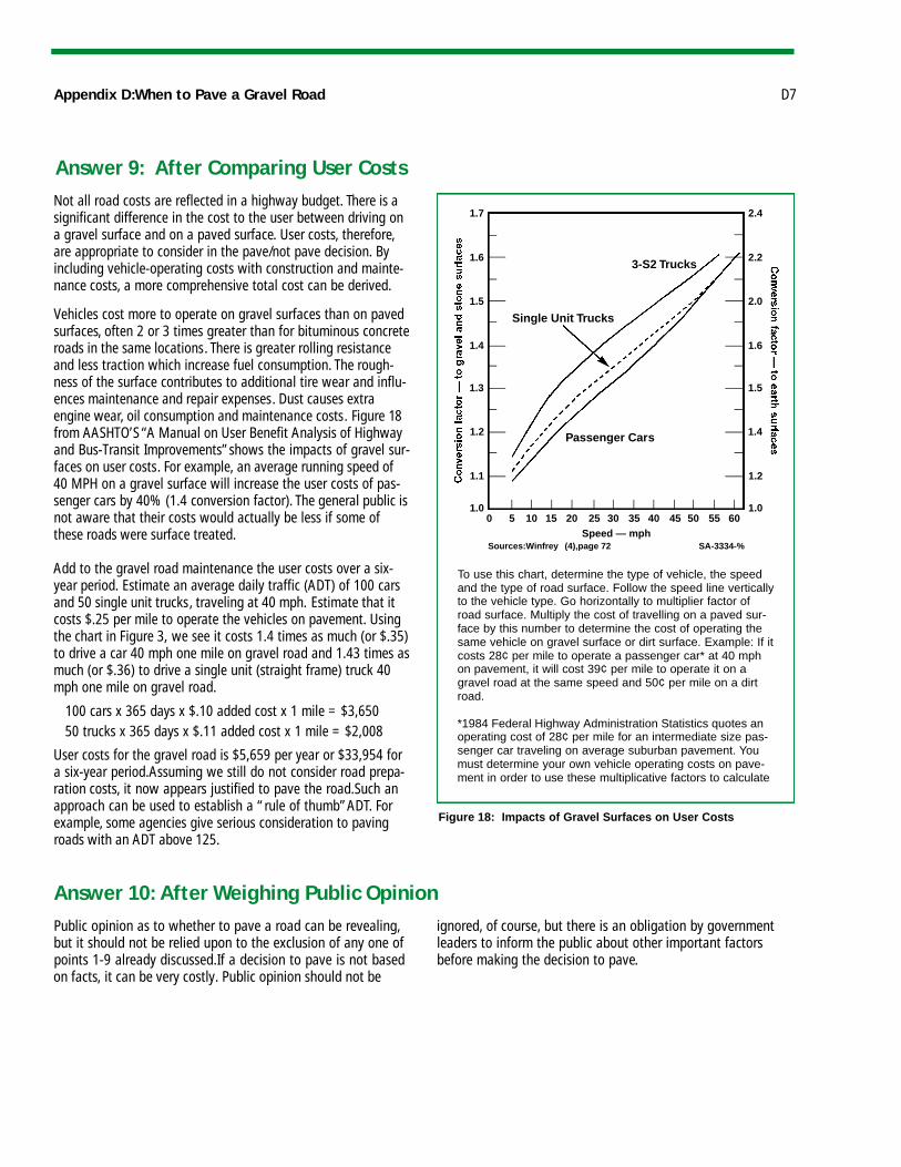
Not all road costs are reflected in a highway budget. There is asignificant difference in the cost to the user between driving ona gravel surface and on a paved surface. User costs, therefore,are appropriate to consider in the pave/not pave decision. Byincluding vehicle-operating costs with construction and mainte-nance costs, a more comprehensive total cost can be derived.
Vehicles cost more to operate on gravel surfaces than on pavedsurfaces, often 2 or 3 times greater than for bituminous concreteroads in the same locations. There is greater rolling resistanceand less traction which increase fuel consumption. The rough-ness of the surface contributes to additional tire wear and influ-ences maintenance and repair expenses. Dust causes extraengine wear, oil consumption and maintenance costs. Figure 18from AASHTO’S “A Manual on User Benefit Analysis of Highwayand Bus-Transit Improvements”shows the impacts of gravel sur-faces on user costs. For example, an average running speed of40 MPH on a gravel surface will increase the user costs of pas-senger cars by 40% (1.4 conversion factor). The general public isnot aware that their costs would actually be less if some ofthese roads were surface treated.
Add to the gravel road maintenance the user costs over a six-year period. Estimate an average daily traffic (ADT) of 100 carsand 50 single unit trucks, traveling at 40 mph. Estimate that itcosts $.25 per mile to operate the vehicles on pavement. Usingthe chart in Figure 3, we see it costs 1.4 times as much (or $.35)to drive a car 40 mph one mile on gravel road and 1.43 times asmuch (or $.36) to drive a single unit (straight frame) truck 40mph one mile on gravel road.
100 cars x 365 days x $.10 added cost x 1 mile = $3,65050 trucks x 365 days x $.11 added cost x 1 mile = $2,008
User costs for the gravel road is $5,659 per year or $33,954 fora six-year period.Assuming we still do not consider road prepa-ration costs, it now appears justified to pave the road.Such anapproach can be used to establish a “rule of thumb”ADT. Forexample, some agencies give serious consideration to pavingroads with an ADT above 125.
Appendix D:When to Pave a Gravel Road D7
Answer 9: After Comparing User Costs
Answer 10: After Weighing Public Opinion
Figure 18: Impacts of Gravel Surfaces on User Costs
To use this chart, determine the type of vehicle, the speedand the type of road surface. Follow the speed line verticallyto the vehicle type. Go horizontally to multiplier factor ofroad surface. Multiply the cost of travelling on a paved sur-face by this number to determine the cost of operating thesame vehicle on gravel surface or dirt surface. Example: If itcosts 28¢ per mile to operate a passenger car* at 40 mphon pavement, it will cost 39¢ per mile to operate it on agravel road at the same speed and 50¢ per mile on a dirtroad.
*1984 Federal Highway Administration Statistics quotes anoperating cost of 28¢ per mile for an intermediate size pas-senger car traveling on average suburban pavement. Youmust determine your own vehicle operating costs on pave-ment in order to use these multiplicative factors to calculate
Public opinion as to whether to pave a road can be revealing,but it should not be relied upon to the exclusion of any one ofpoints 1-9 already discussed.If a decision to pave is not basedon facts, it can be very costly. Public opinion should not be
ignored, of course, but there is an obligation by governmentleaders to inform the public about other important factorsbefore making the decision to pave.
0 5 10 15 20 25 30 35 40 45 50 55 60Speed — mph
Sources:Winfrey (4),page 72 SA-3334-%
1.7
1.6
1.5
1.4
1.3
1.2
1.1
1.0
2.4
2.2
2.0
1.6
1.5
1.4
1.2
1.0
Passenger Cars
3-S2 Trucks
Single Unit Trucks

Local government may consider using “stage constructiondesign”as an approach to improving roads. This is how itworks. A design is prepared for the completed road,from baseand drainage to completed paving. Rather than accomplishingall the work in one season, the construction is spread out overthree to five years. Paving occurs only after the base anddrainage have been proven over approximately one year.Crushed gravel treated with calcium chloride serves as thewearing course for the interim period. Once all weak spotshave been repaired,the road can be shaped for paving.
There are some advantages to keeping a road open to trafficfor one or more seasons before paving:
1. Weak spots that show up in the sub-grade or base can be corrected before the hard surface is applied,eliminating later expensive repair;
2. Risky late season paving is eliminated;3. More mileage is improved sooner;4. The cost of construction is spread over several years.
Note:Advantages may disappear if timely maintenance is notperformed. Surface may deteriorate more rapidly because it isthinner than a designed pavement.
Some local roads are not well engineered. Today, larger vol-umes of heavy trucks and other vehicles are weakening themat a fast rate. Paving roads as a sole means of improving themwithout considering other factors is almost always a costly
mistake. Counties and cities should consider these ten pointsfirst. Carefully considering them will help to assure local government officials that they are making the right decisionabout paving a gravel road.
Stage Construction
Summary
D8 Appendix D:When to Pave a Gravel Road