Embed Size (px)
Citation preview

Size А4
Road Blocker AUIA-ТК-373 (Tyre Killer)
Installation and Operation Manual Revision 2.0 09.2016
www.tiso.ua e-mail: [email protected]
Page-1-
ROAD BLOCKING SYSTEMS
Road Blocker with Built-In Hydraulic Unit Installation and Operation
Manual AUIA-ТК-373(Tyre Killer)
72 Yamska str., Kyiv 03680, Ukraine, Tel.:+380 (44) 461-79-69, Fax:+380 (44) 586-46-51
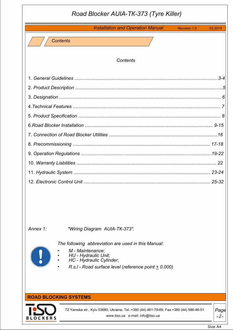
1. General Guidelines ...............................................................................................................3-4
2. Product Description ..................................................................................................................5
3. Designation ............................................................................................................................. 6
4.Technical Features .................................................................................................................. 7
5. Product Specification .............................................................................................................. 8
6.Road Blocker Installation ................................................................................................... 9-15
7. Connection of Road Blocker Utilities ....................................................................................16
8. Precommissioning .......................................................................................................... 17-18
9. Operation Regulations .....................................................................................................19-22
10. Warranty Liabilities ............................................................................................................ 22
11. Hydraulic System ........................................................................................
12. Electronic Control Unit .................................................................................................. 25-32
Annex 1: "Wiring Diagram AUIA-ТК-373".
Contents
Contents
The following abbreviation are used in this Manual: • M - Maintenance;
HU - Hydraulic Unit;•HC - Hydraulic Cylinder;•R.s.l - Road surface level (reference point + 0.000)•
Size А4
Installation and Operation Manual Revision 1.0 03.2015
www.tiso.ua e-mail: [email protected]
ROAD BLOCKING SYSTEMS
Road Blocker AUIA-ТК-373 (Tyre Killer)
72 Yamska str., Kyiv 03680, Ukraine, Tel.:+380 (44) 461-79-69, Fax:+380 (44) 586-46-51
.................. 23-24

Size А4
Revision 1.0 03.2015
www.tiso.ua e-mail: [email protected]
Page-3-
ROAD BLOCKING SYSTEMS
1. General Guidelines:
•
•
1.1 Instructions to installer:
1. The equipment installation instructions shall be complied with for the purpose of safety.
2. The road blocker shall be installed according to the code of practice in compliancewith safety regulations for installation.
3. The equipment shall be installed when it is deenergized.4. Packing materials are subject to disposal according to the applicable standards.
5. The road blocker installation procedure, specified in the instruction, shall be strictlyobserved.
6. It is forbidden to modify the equipment configuration and to use materials and components being outside the scope of delivery and not specified by this Manual.
7. It is forbidden to install equipment during thunderstorm, heavy rain or snowfall, inexplosive environment and obscured conditions.
8. Installation area shall be prepared according to the applicable standards.
9. The road blocker shall be installed, connected and precommissioned by qualifiedprofessionals.
10. When faults or defects are detected, the Supplier's service department shall be referredto.
11. The "TiSO Blockers" Company shall not be liable for the equipment operation in thefollowing events:noncompliance with installation procedure,•use of nonstandard materials and components,•performance of work by unqualified personnel.•
12. The "TiSO Blockers" Company shall not be liable for compliance with safety measuresduring installation of equipment by the personnel outside the Company's servicedepartment.
13. Upon completion of installation the road blocker housing shall be sealed (in the specifiedpoints).
14. Commissioning of equipment shall be documented with appropriate deed to be kept forfurther use.
The information about installation of equipment (date, company, terms, precommissioning results, sealer No., deed of commissioning No.) are recorded in the service book to ensure the manufacturer's warranty liabilities.
Road Blocker AUIA-ТК-373 (Tyre Killer)
Installation and Operation Manual
72 Yamska str., Kyiv 03680, Ukraine, Tel.:+380 (44) 461-79-69, Fax:+380 (44) 586-46-51
72 Yamska str., Kyiv 03680, Ukraine, Tel.:+380 (44) 461-79-69, Fax:+380 (44) 586-46-51
The Manual should be scrutinized prior to the equipment installation and operation; The Manual should be kept for future use.

1.2 Instructions to user:
1. The operation regulations, prescribed by this Manual, shall be strictly observed.No modifications of the equipment components shall be made.2.The equipment shall be used for intended purposes, specified by the manufacturer.3.
4. Don't try to repair or adjust the road blocker on your own.The relevant servicedepartment shall be referred to. Breaking of seals shall cancel the manufacturer'swarranty liabilities.
5. The road blocker control units (panels) shall be beyond the reach of outsiders.
6. The "TiSO Blockers" Company shall not be liable for improper operation of equipmentand violation of safety measures by the user.
• In case of improper operation and noncompliance with requirements ofinstruction manuals the road blocker may constitute a danger to life andhealth of people by presence of increased voltage in electric circuits andmovable parts!
• The road blocker must be operated by the personnel having at least level IIof electrical safety qualification. The road blocker should be serviced andrepaired by the personnel having at least level III of qualification and beingfamiliar with the product design and instruction manuals:- installation and operation manual;- datasheet;- instruction manuals for components.
• Technical inspections, maintenance, adjustment and repair shall beperformed only when the road blocker is deenergized.
This manual is an integral part of the product and shall be handed over to the customer. The manual shall be kept for future use and to be consulted, if appropriate. If the road blocker is resold, handed over to another owner or transported to another place, make sure that this manual is enclosed to the product to be used by new owner and/or maintenance staff during installation and/or operation.
Compare with the data specified in the product datasheet and the warranty coupon.
Make sure of availability of factory seals and the plate with manufacturer's details:
Size А4
Revision 1.0 03.2015
www.tiso.ua e-mail: [email protected]
Page-4-
ROAD BLOCKING SYSTEMS
Manufacturer;•Product type;•Date of manufacture;•Model No. ХХ ХХ;•Serial No. ХХХ ХХ ХХ.•
Road Blocker AUIA-ТК-373 (Tyre Killer)
Installation and Operation Manual
72 Yamska str., Kyiv 03680, Ukraine, Tel.:+380 (44) 461-79-69, Fax:+380 (44) 586-46-51
150
*
Size А4
Revision 1.0 03.2015
www.tiso.ua e-mail: [email protected]
Page-5-
ROAD BLOCKING SYSTEMS
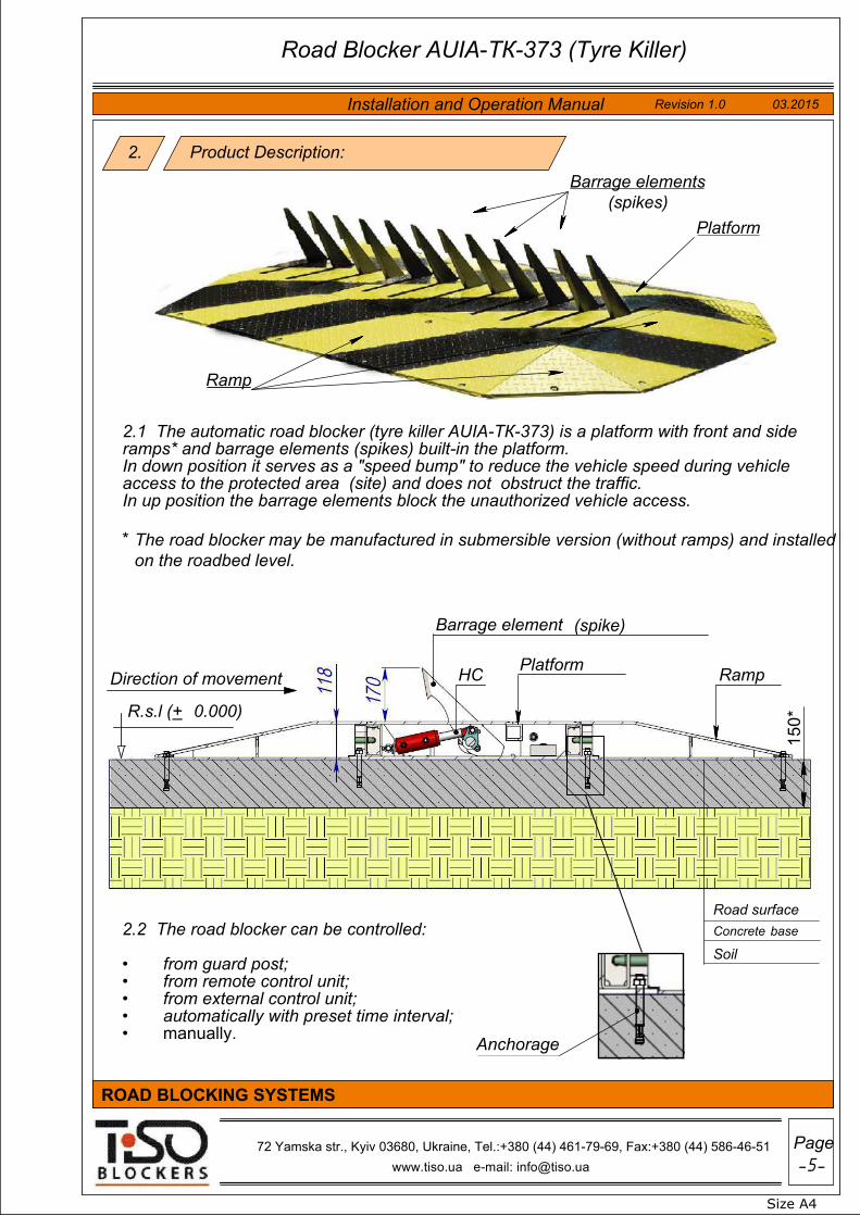
2. Product Description:
2.1 The automatic road blocker (tyre killer AUIA-ТК-373) is a platform with front and side ramps* and barrage elements (spikes) built-in the platform. In down position it serves as a "speed bump" to reduce the vehicle speed during vehicle access to the protected area (site) and does not obstruct the traffic. In up position the barrage elements block the unauthorized vehicle access.
* The road blocker may be manufactured in submersible version (without ramps) and installedon the roadbed level.
Platform
Ramp
Barrage elements (spikes)
2.2 The road blocker can be controlled:
from guard post;•from remote control unit;•from external control unit;•automatically with preset time interval;•manually.•
Road surface
SoilConcrete base
R.s.l (+ 0.000)
Direction of movement
HC Platform
Ramp
Barrage element
(spike)
Road Blocker AUIA-ТК-373 (Tyre Killer)
Installation and Operation Manual
72 Yamska str., Kyiv 03680, Ukraine, Tel.:+380 (44) 461-79-69, Fax:+380 (44) 586-46-51
Anchorage

3. Designation
3.1 The road blockers are used at public, commercial and private facilities for unauthorized vehicle access control, vehicular traffic management and regulation at different sites and adjacent areas.
3.2 The road blockers are recommended for passenger transport facilities, approaches to sports facilities and government facilities, to be installed in front of shops, hotels, shopping malls and office centers, health care facilities, at the approaches to cottages and cottage settlements, at central urban and historical sites, industrial and special facilities.
3.3 The road blockers (tyre killers) can be installed in conjunction with other traffic control and unauthorized access prevention equipment.
3.4 By impact of environmental factors the road blocker complies with GOST 15150-69 and is designed for operation in moderate climate (Y1) with acceptable ambient temperature - 30°С to +45°С.
Size А4
Revision 1.0 03.2015
www.tiso.ua e-mail: [email protected]
Page-6-
ROAD BLOCKING SYSTEMS
Road Blocker AUIA-ТК-373 (Tyre Killer)
Installation and Operation Manual
72 Yamska str., Kyiv 03680, Ukraine, Tel.:+380 (44) 461-79-69, Fax:+380 (44) 586-46-51

Size А4
Revision 1.0 03.2015
www.tiso.ua e-mail: [email protected]
ROAD BLOCKING SYSTEMS
4. Technical Features:
Model AUIA-ТК-372 surface-mount*
hydraulic
2 2020х770x1182640x3170x118
AUIA-ТК-373 / submersible / integrated
170 3
3000х 770 х118 3620x3170x118
10structural steel С22
3 32 2
~ 220V, 50/60Hz550 W
IP 67IP 55
-10 /+50
-30 / +50
hydraulic unit hydraulic lock
Manual unlocking mechanical device
Power cable 12 х 0,75 mm2
Installation type Actuator type / location Spike lift height, mm Blocking width , m Road blocker dimensions, mm Dimensions with ramp*, mm Max. axle weight limit, tn Material Raising time, s Sinking time Power supply Power consumption Road blocker index of protection Control box index of protection Weight (with ramps), kg Temperature conditions, С
Heating system temperature conditions (optional),C
Raised position locking
Manual emergency sinking
Cable for connection road blocker to control box (is not included in the scope of delivery)
Operation conditions Intensive
pitch 165*
Road Blocker AUIA-ТК-373 (Tyre Killer)
Installation and Operation Manual
72 Yamska str., Kyiv 03680, Ukraine, Tel.:+380 (44) 461-79-69, Fax:+380 (44) 586-46-51
2000 / 3000
770
170
118
770
350 W
1110 1540

Side ramp;
1 23
32
2. Front ramp;
Key-words:
Road blocker assembly;1.
4. Box with electronic control unit.3.
4
Road Blocker. Scope of Delivery
5. Specification
Size А4
Revision 1.0 03.2015
www.tiso.ua e-mail: [email protected]
Page-8-
ROAD BLOCKING SYSTEMS
Road Blocker AUIA-ТК-373 (Tyre Killer)
Installation and Operation Manual
72 Yamska str., Kyiv 03680, Ukraine, Tel.:+380 (44) 461-79-69, Fax:+380 (44) 586-46-51

-9-
Size А4
03.2015 Revision 1.0
www.tiso.ua e-mail: [email protected]
Page
ROAD BLOCKING SYSTEMS
6. Road Blocker Installation
7.Reinforcing net (reinforcement cage) to be installed;8.
150mm concrete layer to be poured (Concrete М400. GOST 7473-94).9.
• Installation of utility conduit;• Arrangement of concrete base (foundation);
•
•
•
•
•
•
6.1 Arrangement of installation site:
6.2 Installation sequence:
• Preparation of installation pit;
Installation of road blocker in the designed position;
* If surface mounted.
• Connection of utilities.• Installation of ramps in the designed position*;•
6.3 Installation procedure:
6.3.1 Preparation of installation pit for surface-mount installation:
The required marking according to the design solutions to be made;1.The roadbed to be removed, if appropriate;2.A pit with dimensions of 1400mm х 3800mm and depth of 400 mm to be dug;3.50 mm sand cushion to be prepared;4.Geotextile to be put on the pit bottom (GOST R 50275-92);5.The pit to be filled with gravel (10-20mm grain size) GOST 8267-93 at the height of 200mm;6.Drain pipes of ø75mm Н=210mm to be installed into gravel at the depth of 50mm;
• Reinforcing and concreting shall be performed according to theapplicable standards;It is advised to use waterproof additives to obtain water-resistant concrete.•
Road Blocker AUIA-ТК-373 (Tyre Killer)
72 Yamska str., Kyiv 03680, Ukraine, Tel.:+380 (44) 461-79-69, Fax:+380 (44) 586-46-51
Installation and Operation Manual
Arrangement of installation site must comply with requirements of applicable regulations and standards.Installation area shall be fenced along perimeter with temporary security fencing orcaution tape at the distance of 3 meters from the installation site.
The appropriate warning signs GOST (State Standard) 12.4.026-76 CCBT (Labour Safety Standards System) shall be installed in front of the entrance to the installation site.
Make sure that there are no underground utilities at the installation site!Keep outsiders away from the installation site!Safety regulations must be observed during installation!

R.s.l (+ 0.000)
-10-
Size А4
03.2015 Revision 1.0
www.tiso.ua e-mail: [email protected]
Page
ROAD BLOCKING SYSTEMS
Direction of movement
6.3.1 The pit for the road blocker surface-mount installation
Reinforcement cage (Reinforcing net) can be delivered as additional option along with the road blocker or can be manufactured by the site supervisor according to drawings of the company "TISO BLOCKERS".
6.3.2 Preparation of installation pit for submersible installation:
The required marking according to the design solutions to be made;1.The roadbed to be removed, if appropriate;2.A pit with dimensions of 1400mm х 3800mm, and depth of 530*mm to be dug;3.50 mm sand cushion to be prepared;4.Geotextile to be put on the pit bottom (GOST R 50275-92);5.The pit to be filled with gravel (10-20mm grain size) GOST 8267-93 at the height of 200mm;6.Drain pipes of ø50mm Н=210mm to be installed into gravel at the depth of 50mm;7.Reinforcing net (reinforcement cage) to be installed;8.150mm concrete layer to be poured (Concrete М400. GOST 7473-94).9.Formwork to be installed (outer dimensions:770х3020mm Н=150mm);10.Reinforcing net (reinforcement cage) to be installed;11.120 mm second concrete layer to be poured (Concrete М400. GOST 7473-94).12.
Sand cushion, 50 mmlayer;
•
Soil.•SECTION 1-1 SCALE 1 : 20
• Reinforced concrete(М400), 150mm layer;
• Gravel (10-20mm grainsize), 200mm layer ;
Geotextile;•
Drain pipe Reinforcing net
400
50
150
2
00
75
3800
140
0 1400 1400
11
Road Blocker AUIA-ТК-373 (Tyre Killer)
72 Yamska str., Kyiv 03680, Ukraine, Tel.:+380 (44) 461-79-69, Fax:+380 (44) 586-46-51
Installation and Operation Manual

R.s.l (+ 0.000))
•
•
•
•
•
•
6.3.2 The pit for the road blocker submersible installation
Size А4
Revision 1.0 03.2015
www.tiso.ua e-mail: [email protected]
Page-11-
ROAD BLOCKING SYSTEMS
Utility conduit tube
Direction of movement
3800
1400
77
0 3020
2 2
Formwork
•
When concrete is hardened:
SECTION 2-2 SCALE 1 : 20
Formwork
• Formwork to be removed;
75mm
Reinforcing
Drain pipe
Installation site to be prepared for the road blocker installation in the designedposition.
• Reinforcing and concreting shall beperformed according to the applicablestandards;
•It is advised to use waterproofadditives to obtain water-resistantconcrete.
120
1
50
200
50
530
Road Blocker AUIA-ТК-373 (Tyre Killer)
72 Yamska str., Kyiv 03680, Ukraine, Tel.:+380 (44) 461-79-69, Fax:+380 (44) 586-46-51
Installation and Operation Manual
Reinforced concrete (М400), 120mm layer;
Reinforced concrete (М400), 150mm layer;
Gravel (10-20mm grainsize), 200mm layer ;
Geotextile;
Sand cushion, 50 mmlayer;
Soil.
1400 1400
175

Size А4
Revision 1.0 03.2015
www.tiso.ua e-mail: [email protected]
Page-12-
ROAD BLOCKING SYSTEMS
6.3.3 The Road Blocker installation in the designed position:
Sequence of operations:
1. The product to be unpacked;Outside condition and configuration of the road blocker to be checked;2.The road blocker to be installed in the predesign position;3.Eye-bolts М16 to be installed;4.The road blocker to be installed in the designed position by means of handlingequipment.
5.
•
•
Presence of unauthorized persons at the installation site during handling operations is PROHIBITED!
•
The road blocker is installed in the designed position by means of handling equipment.
Eye-bolt М16 ____m
2000/3000
118
770
Road Blocker AUIA-ТК-373 (Tyre Killer)
72 Yamska str., Kyiv 03680, Ukraine, Tel.:+380 (44) 461-79-69, Fax:+380 (44) 586-46-51
Installation and Operation Manual
Safety regulations must be observed according to the applicable standards during handling operations! Slinging must be performed by the properly qualified slingers having the appropriate permit to work;

Chequered plate (lid)
400* 400*
400
* 4
00*
770
3000
3
3The road blocker in the designed position when it is surface mounted:
Direction of movement
Sequence of operations:
6. The road blocker chequered plate (lid) to be removed;
7. The road blocker to be fixed in the designed position bymeans of anchorage;
8. Utility conduit to be put into channel.
Utility conduit channel
Utility conduit
50
60 150
Size А4
Revision 1.0 03.2015
www.tiso.ua e-mail: [email protected]
Page-13-
ROAD BLOCKING SYSTEMS
SECTION 3-3 SCALE 1 : 10
The road blocker horizontal position according to compliance with the design reference marks shall be checked by means of leveling instrument prior to its fixation. The road blocker submersible installation and fixation is performed similarly.
Road Blocker AUIA-ТК-373 (Tyre Killer)
72 Yamska str., Kyiv 03680, Ukraine, Tel.:+380 (44) 461-79-69, Fax:+380 (44) 586-46-51
Installation and Operation Manual

Electric cables
to control unit
Junction tube
Terminal block
Size А4
Revision 1.0 03.2015
www.tiso.ua e-mail: [email protected]
Page-14-
ROAD BLOCKING SYSTEMS
Front and side ramps to be installed and fastened after the road blocker is fixed in the designed position:
Road blocker revisionbox
Electric cable ends shall be brought in through utility conduit channel into the road blocker revision box from the utility conduit side prior to installation of side ramp.
Front ramp
Front ramp
Side ramp
Ramps are fastened by means of mechanical fixation specified by fixturing design.
Side ramp
Road blocker
(conventionally)
Road Blocker AUIA-ТК-373 (Tyre Killer)
72 Yamska str., Kyiv 03680, Ukraine, Tel.:+380 (44) 461-79-69, Fax:+380 (44) 586-46-51
Installation and Operation Manual

The Road Blocker AUIA-ТК-373 (Tyre Killer). General Appearance
Size А4
Revision 1.0 03.2015
www.tiso.ua e-mail: [email protected]
Page-15-
ROAD BLOCKING SYSTEMS
Road Blocker AUIA-ТК-373 (Tyre Killer)
72 Yamska str., Kyiv 03680, Ukraine, Tel.:+380 (44) 461-79-69, Fax:+380 (44) 586-46-51
Installation and Operation Manual

up to 100 m
-16-
Size А4
Revision 1.0
www.tiso.ua e-mail: [email protected]
03.2015
Page
ROAD BLOCKING SYSTEMS
Road Blocker AUIA-ТК-373 (Tyre Killer)
Designed position*
Designed position* * to be specified by the customer's individualdesign solutions.
2.
The road blocker utilities must be connected when it is deenergized!The relevant instructions should be strictly followed during connection!•
4.
7.
•
•
3.
Connection of Road Blocker Utilities
prior to its connection.
Heat shrink sleeves to be used for cable connection (not included in the scope of delivery);
The road blocker utilities must be connected only by the properlyqualified professionals!
7.1 Road Blocker connection to control unit
1. The relevant ends of electric cables of control unit and road blocker to be connected on theterminal block of road blocker and control unit (See section "Electronic Control Unit. RoadBlocker connection", pages 22-25 of this Manual);
•
Make sure of the road blocker installation accuracy and attachment security
Electronic control unit
Road Blocker AUIA-ТК-373 (Tyre Killer)
Installation and Operation Manual
50 cm cable length margin from each side to be left to ensure remedial maintenance;
Cable length margin to be folded inwards utility conduit.
72 Yamska str., Kyiv 03680, Ukraine, Tel.:+380 (44) 461-79-69, Fax:+380 (44) 586-46-51

•The required equipment performance parameter setting to be set, if appropriate.Oil to be refilled after hydrauluc unit is actuated and air is removed from hydrauliccylinders;If a fault is detected it is necessary to trace the trouble and remedy it, if applicable*.•(* See Table 1).
•
8.1 Preparation for precommissioning:
•
8. Precommissioning:
Reliability of connection with earth loop to be checked.• The equipment power network to be checked;• The roadbed around road blocker to be restored;
Compliance and reliability of the road blocker, hydraulic unit and control unit electrical cable connections to be checked;
•
8.2 Precommissioning:
Hydraulic unit and control unit to be energized;•Road blocker trial operation to be conducted;•
The following shall be checked while conducting trial operation:
Hydraulic unit operation parameters;1.Control unit and remote control panel operation parameters;2.Road blocker operation parameters.3.
to prevent blocker raising/sinking of the road blocker spikes;1.to touch the road blocker's moving parts during its operation;2.to initiate movement of vehicles prior to complete sinking of the roadblocker's barrage elements (spikes).
3.
The area adjacent to road blocker shall be free and clear of foreign items.
• Commissioning, equipment adjustment, troubleshooting shall beperformed only by the properly qualified professionals!
Safety regulations should be strictly observed during commissioning andequipment adjustment!
•
It is forbidden:•
-17-
Size А4
03.2015 Revision 1.0
www.tiso.ua e-mail: [email protected]
Page
ROAD BLOCKING SYSTEMS
72 Yamska str., Kyiv 03680, Ukraine, Tel.:+380 (44) 461-79-69, Fax:+380 (44) 586-46-51
Road Blocker AUIA-ТК-373 (Tyre Killer)
Installation and Operation Manual
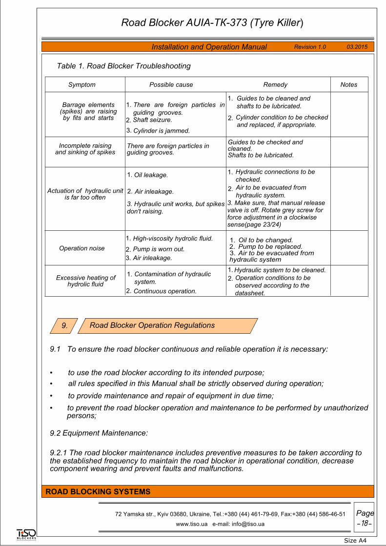
9.2.1 The road blocker maintenance includes preventive measures to be taken according to the established frequency to maintain the road blocker in operational condition, decrease component wearing and prevent faults and malfunctions.
Table 1. Road Blocker Troubleshooting
9.2 Equipment Maintenance:
Road Blocker Operation Regulations
to prevent the road blocker operation and maintenance to be performed by unauthorizedpersons;
• to provide maintenance and repair of equipment in due time;• all rules specified in this Manual shall be strictly observed during operation;• to use the road blocker according to its intended purpose;
9.1
To ensure the road blocker continuous and reliable operation it is necessary:
•
9.
Symptom Possible cause Remedy Notes
Barrage elements (spikes) are raising by fits and starts
1. There are foreign particles inguiding grooves.
2. Shaft seizure.3. Cylinder is jammed.
1. Guides to be cleaned andshafts to be lubricated.
2.
Incomplete raising and sinking of spikes
There are foreign particles in guiding grooves.
Guides to be checked and cleaned. Shafts to be lubricated.
Actuation of hydraulic unit is far too often
1. Oil leakage.
2. Air inleakage.
1. Hydraulic connections to bechecked.
2. Air to be evacuated fromhydraulic system.
Operation noise1. High-viscosity hydrolic fluid.
2. Pump is worn out.3. Air inleakage.
Excessive heating of hydrolic fluid
1. Contamination of hydraulicsystem.
2. Continuous operation.
1. Hydraulic system to be cleaned.2. Operation conditions to be
observed according to thedatasheet.
-18-
Size А4
03.2015 Revision 1.0
www.tiso.ua e-mail: [email protected]
Page
ROAD BLOCKING SYSTEMS
Road Blocker AUIA-ТК-373 (Tyre Killer)
Installation and Operation Manual
Cylinder condition to be checkedand replaced, if appropriate.
1. Oil to be changed.2. Pump to be replaced.3. Air to be evacuated fromhydraulic system
72 Yamska str., Kyiv 03680, Ukraine, Tel.:+380 (44) 461-79-69, Fax:+380 (44) 586-46-51
3. Hydraulic unit works, but spikes don't raising.
3. Make sure, that manual release valve is off. Rotate grey screw for force adjustment in a clockwise sense(page 23/24)

* See Table 2.
Equipment examination and maintenance shall be performed according to Schedule* and only by properly qualified professionals.
• M-2 (semiannually);• M-1 (monthly);• Daily inspection (each shift);9.2.2 Recommended types of the road blocker maintenance (M):
•
Table 2. Road Blocker maintenance schedule
Major repair (MR) – after 20000 cycles.• M-3 (annually);
M type Frequency Scope of control/work
Daily inspection
each shift
Normally the daily maintenance is performed before commencement of work and includes visual inspection of the road blocker and, if required, prompt mechanical troubleshooting, elimination of corrosion and surface pollution. The following control shall be conducted during daily maintenance:
availability of all units and sensors in their proper locations and their fastening security;
•
performance of all sensors and cable integrity;•road blocker normal operation without jerks and abnormal noises,jamming of movable constructional elements;
•
motor heating (over 70°C).•
M-1 monthly
M-1 is performed monthly and includes the following measures:measures in the scope of daily inspection;•elimination of dust from the road blocker housing and components;•cleaning of actuators, sensors and drive;•verification of sensors fixation reliability and their performance;•verification of good condition and fastening security of cable connectionsto actuators, sensors;
•
check of availability and integrity of protective fences and devices.•
M-2 semiannually
M-2 maintenance is performed semiannually including the following types of work:
measures in the scope of M-1;•verification of fastening security of units and devices.•
M-3 annually
M-3 maintenance is performed annually including the following types of work:
measures in the scope of M-2;•check of status of bearings, sealing cups and lubrication;•blowing and cleaning of terminal boxes;•tensioning of screw joints of terminal boxes;•check of reliability and quality of cable connections and earthing;•check of insulation resistance;•repair of paint coatings.•
-19-
Size А4
03.2015 Revision 1.0
www.tiso.ua e-mail: [email protected]
Page
ROAD BLOCKING SYSTEMS
Road Blocker AUIA-ТК-373 (Tyre Killer)
Installation and Operation Manual
72 Yamska str., Kyiv 03680, Ukraine, Tel.:+380 (44) 461-79-69, Fax:+380 (44) 586-46-51

The hydraulic unit maintenance shall be performed according to the guidelines specified in the hydraulic unit instruction manuals, combining them with M-2 or M-3.
Major repair is recommended to be performed by the manufacturer or dedicated repair service according to the manufacturer’s documentation with the use of the manufacturer’s spare parts as well as restored or manufactured by special repaire facilities according to the manufacturer's documentation. Mean lifetime between major repair is at least 20000 hours.
•
All types of maintenance should be recorded in maintenance and repair work sheet.•
The time of maintenance and major repair can be increased or decreased depending on actual parameters of the road blocker operation and fixed by the company operating this equipment.
9 .3 Safety regulations:The appropriate safety measures shall be observed during operation and maintenance of the road blocker.
9.3.1 IT IS FORBIDDEN TO USE DEFECTIVE APPLIANCES, TOOLS, INSTRUMENTATION THE SERVICE LIFE OF WHICH EXPIRED.
9.3.2 Installation and operation of electrical equipment should be performed at the factory according to the Regulations for Operation of Consumer Electrical Installations, Safety Rules for Operation of Customers' Electrical Installations complied with the Occupational Safety Standards System (GOST 12.3.003, GOST 12.3.019 and GOST 12.3.032).
9.3.3 The road blocker must be repaired by the persons being over 18, having at least level III of electrical safety qualification, relevant permit to work with electrical facilities up to 1000V, be safety briefed at workplace and scrutinized the product instruction manuals.
9.3.4 It shall be the responsibility of the owner to ensure safety measures.
3.3.5 Hazardous characteristics during the road blocker operation are:
mechanical impact of raising/sinking dynamic part and•
electric shock by 220V/380V.•
-20-
Size А4
03.2015 Revision 1.0
www.tiso.ua e-mail: [email protected]
Page
ROAD BLOCKING SYSTEMS
Road Blocker AUIA-ТК-373 (Tyre Killer)
Installation and Operation Manual
72 Yamska str., Kyiv 03680, Ukraine, Tel.:+380 (44) 461-79-69, Fax:+380 (44) 586-46-51

9.3.6 Service and repair shall be performed only when equipment is deenergized, a forbidding safety sign according to GOST 12.4.026 with notation “DO NOT SWITCH ON MEN WORKING!” is put on initiator. After completion of works safety signs should be removed and equipment should be actuated only upon authorization of the work superintendent.
9.3.7 The road blocker electrical equipment should be earthed. Resistance between earthing bus and each accessible metal non-current-carrying part of the road blocker electrical equipment housing should not exceed 4 Ohm.
9.3.8 It is forbidden:
to perform maintenance and repair works when the road blocker electrical equipment is energized.
•
to perform maintenance and repair works when equipment is in operation.•
9.3.9 The regulations specified in the documents listed below should be observed when using the road blocker:
"Regulations for Operation of Consumer Electrical Installations";•"Interbranch rules on labor safety during operation of electricity generating equipment";•"Electrical Installations Code";•GOST 12.0.004-90; GOST 12.1.019-85; GOST 12.3.019-80.•
9.3.10 General safety requirements accepted in the particular company should be in effect during installation and operation of the road blocker. The safety requirements according to GOST 9.014-78 should be observed during preservation and depreservation.
9.3.11 Fire safety regulations should be observed when paraffin oil for rinsing of units and parts is used.
9.3.12 The safety instructions specified in instruction manuals for purchased products and control system should be additionally governed by.
9.3.13 The road blocker operating in conjunction with other technological equipment should have common locking with it.
-21-
Size А4
03.2015 Revision 1.0
www.tiso.ua e-mail: [email protected]
Page
ROAD BLOCKING SYSTEMS
Road Blocker AUIA-ТК-373 (Tyre Killer)
Installation and Operation Manual
72 Yamska str., Kyiv 03680, Ukraine, Tel.:+380 (44) 461-79-69, Fax:+380 (44) 586-46-51
Switch is mounted to place of control box connection to the network.
-22-
Size А4
03.2015 Revision 1.0
www.tiso.ua e-mail: [email protected]
Page
ROAD BLOCKING SYSTEMS
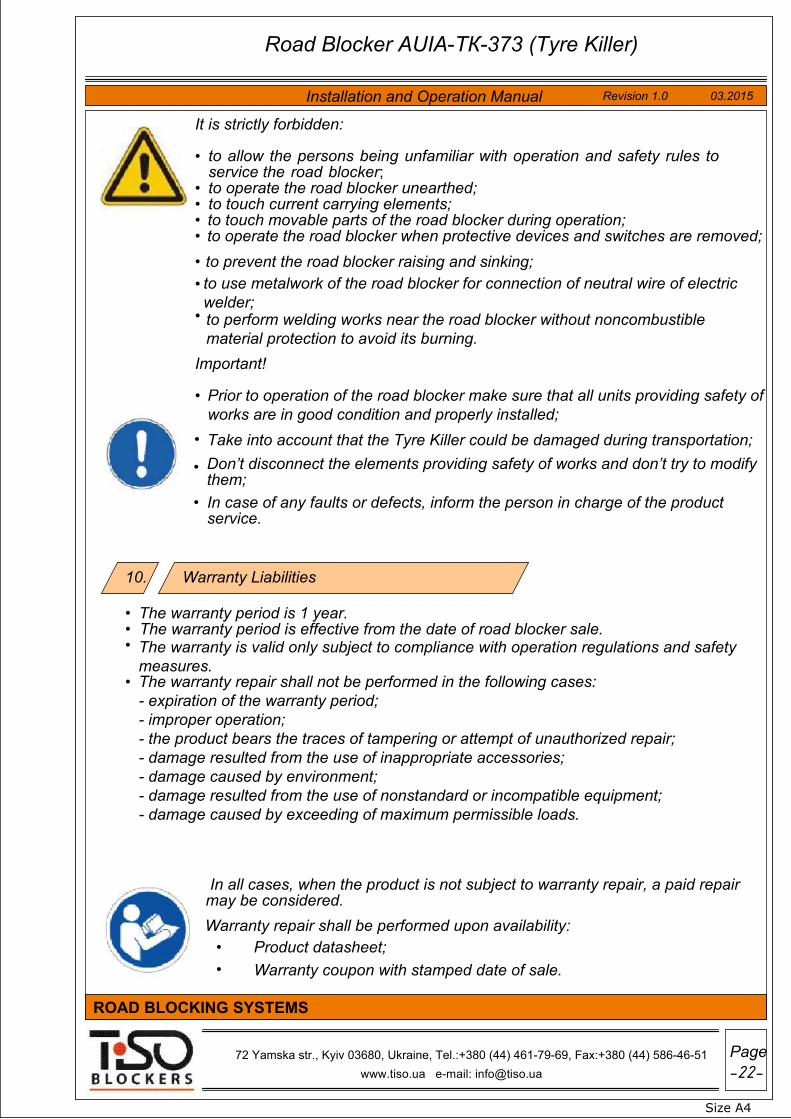
The warranty period is 1 year.•The warranty period is effective from the date of road blocker sale.•The warranty is valid only subject to compliance with operation regulations and safetymeasures.
•
The warranty repair shall not be performed in the following cases:- expiration of the warranty period;- improper operation;- the product bears the traces of tampering or attempt of unauthorized repair;- damage resulted from the use of inappropriate accessories;- damage caused by environment;- damage resulted from the use of nonstandard or incompatible equipment;- damage caused by exceeding of maximum permissible loads.
•
In all cases, when the product is not subject to warranty repair, a paid repair may be considered.
Warranty Liabilities
It is strictly forbidden:
• to allow the persons being unfamiliar with operation and safety rules toservice the road blocker;to operate the road blocker unearthed;•to touch current carrying elements;•to touch movable parts of the road blocker during operation;•to operate the road blocker when protective devices and switches are removed;•to prevent the road blocker raising and sinking;•to use metalwork of the road blocker for connection of neutral wire of electricwelder;
•
to perform welding works near the road blocker without noncombustiblematerial protection to avoid its burning.
•
Important!
Prior to operation of the road blocker make sure that all units providing safety of works are in good condition and properly installed;
•
• Take into account that the Tyre Killer could be damaged during transportation;
• Don’t disconnect the elements providing safety of works and don’t try to modifythem;
• In case of any faults or defects, inform the person in charge of the productservice.
Warranty repair shall be performed upon availability:Product datasheet;•Warranty coupon with stamped date of sale.•
10.
Road Blocker AUIA-ТК-373 (Tyre Killer)
Installation and Operation Manual
72 Yamska str., Kyiv 03680, Ukraine, Tel.:+380 (44) 461-79-69, Fax:+380 (44) 586-46-51

-23-
Size А4
03.2015 Revision 1.0
www.tiso.ua e-mail: [email protected]
Page
ROAD BLOCKING SYSTEMS
11a. Road Blocker Hydraulic System
Recommended hydraulic fluid: SEA-OX29 11a.3
Hydraulic Unit SEA Maxi-4:
11a.1 The road blocker hydraulic actuation is provided by hydraulic unit SEA Maxi-4
11a.2 Hydraulic unit oil:
l/min 4 MPa 4.5
SEA Maxi-4 basic technical specifications
Maximum pump capacity Operating pressure
MotorPump
Shaft speed rpm 2800Alternate current V 230Solenoid power supply Motor capacity
V 24 W 550
72 Yamska str., Kyiv 03680, Ukraine, Tel.:+380 (44) 461-79-69, Fax:+380 (44) 586-46-51
Road Blocker AUIA-ТК-373 (Tyre Killer) for 3000 mm
Installation and Operation Manual
Винты предназначены
для
регулировки
прилагаемого
усилия:
Screw for force adjustment:Grey - up Yellow - down
Серый - подъем
Желтый - опускание
Гидравлическая
линия 1(подъем)Гидравлическая
линия 2(опускание)
Hydraulic line 1(up)
Hydraulic line 2(down)
Кабель электропривода: -Синий провод - общий -Черный провод - Открывание/Закрывание + Конденсатор -Коричневый провод - Закрывание/открывание -Желто-зеленый провод - Заземление
Motor cable: -Blue - Common -Black - Opening/Closing+Capacitor -Brown - Closing/Opening+Capacitor -Yellow/Green - Ground
Пробка
маслозаливного
отверстияOil refilling cap
Уровень
масла
Oil level
552
mm

-
Size А4
03.2015 Revision 1.0
www.tiso.ua e-mail: [email protected]
Page
ROAD BLOCKING SYSTEMS
11b. Road Blocker Hydraulic System
Recommended hydraulic fluid: SEA-OX29 11b.3
Hydraulic Unit SEA Regular-4:
11b.1 The road blocker hydraulic actuation is provided by hydraulic unit SEA Regular-4
l/min 4 MPa 3.5
SEA Regular-4 basic technical specifications
Maximum pump capacity Operating pressure
MotorPump
rpm 2800 V 230
Shaft speed Alternate current Solenoid power supply Motor capacity
11b.2 Hydraulic unit oil:
V 24 W 350
72 Yamska str., Kyiv 03680, Ukraine, Tel.:+380 (44) 461-79-69, Fax:+380 (44) 586-46-51
Road Blocker AUIA-ТК-372 (Tyre Killer) for 2000 mm
Installation and Operation Manual
Винты предназначены
для
регулировки
прилагаемого
усилия:
Screw for force adjustment:Grey - up Yellow - down
Серый - подъем
Желтый - опускание
Гидравлическая
линия 1(подъем)Гидравлическая
линия 2(опускание)
Hydraulic line 1(up)
Hydraulic line 2(down)
Кабель электропривода: -Синий провод - общий -Черный провод - Открывание/Закрывание + Конденсатор -Коричневый провод - Закрывание/открывание -Желто-зеленый провод - Заземление
Motor cable: -Blue - Common -Black - Opening/Closing+Capacitor -Brown - Closing/Opening+Capacitor -Yellow/Green - Ground
Пробка
маслозаливного
отверстияOil refilling cap
Уровень
масла
Oil level
470
mm
-24

Principle of operationThe Road Blocker (Tyre Killer) executes the following commands: spikes raising, spikes sinking, spikes stopping.
Spikes Raising
This command can be initiated by pushing the “Up” button on remote control panel by impermanent connection of the potential control inputs 16 “INP "UP"” and 20 "GND" of the terminal block X5. INP1of the controller PCB349.003.
When this command is executed, the Road Blocker spikes start raising until reaching the uppermost position of the top position sensor or termination of 5 sec. raising timeout or until reaching the uppermost position (limit stop). When spikes are moving up, the green LED display "Up" will be blinking on the remote control panel, and after actuation of the uppermost position sensor and spikes stopping it will be lit (up position display).
Spikes Sinking
This command can be initiated by pushing the "Down" button on the remote control panel by impermanent connection of the potential control inputs 18 “INP "DOWN"” and 20 "GND" of the terminal block X5. INP1 of the controller PCB349.003.
When this command is executed, the Road Blocker spikes start sinking until reaching the lowermost position (limit stop) or termination of 5 sec. sinking timeout. When spikes are moving down, the green LED display "Down" will be blinking on the remote control panel, and after actuation of the lowermost position sensor and spikes stopping it will be lit (down position display).
Spikes Stopping
This command can be initiated by pushing the "STOP" button on the remote control panel or by impermanent connection of the potential control inputs 17. “INP "STOP"” and 20 “GND” of the terminal block X5. INP1 and the controller PCB349.003.
When this command is executed while spikes are raising or sinking, the Road Blocker stops and will be fixed until other commands are completed.
Формат А4
72, Yamska Str., Kyiv, 03680, Ukraine, tel.:+380 (44) 461-79-69, fax:+380 (44) 586-46-51
www.tiso.ua e-mail: [email protected] -25-
ROAD BLOCKING SYSTEMS
Installation and Operation Manual
Road Blocker AUIA-ТК-373 (Tyre Killer)
Revision 2.0 09.2016
Page
Electronic Control Unit 12.

DESCRIPTION AND OPERATION OF THE ROAD BLOCKER ELECTRIC PARTS
The Road Blocker consists of one control box (B1. Electronic Control Unit), two blockers (B2. Blocker 1) and (B3. Blocker 2) and a wire remote control unit (B4. Wire Remote Control Unit)
Electronic control box is assembled in wall-mount plastic case and has the moisture and dust protection index IP55. The control box includes:
- B1-А1.Power Supply Unit LPV-20-12 (Power Supply Unit LPV-20-12)- B1-C1. Capacitor C1. (20 mF 400V)- B1-C2. Capacitor C2. (25 mF 400V)- B1-A2. Controller (Controller PCB349.003)- B2-А1. Hydraulic Unit 1 (Hydro Station Maxi-6)- B2-А2. Uppermost and Lowermost Position Sensors (Limit Switch S-2 (2 pcs))- B2-TX1. Inspection Box and Terminal Block of the Blocker 2 (Blocker connection block)
- B3-А1. Hydraulic Unit 2 (Hydro Station Regular-4)- B3-А2. Uppermost and Lowermost Position Sensors (Limit Switch S-2 (2 pcs))- B3-TX1. Inspection Box and Terminal Block of the Blocker 1 (Blocker connection block)
- B4-А1. Remote Control Panel (Remote Control Unit PCB 111.22.00.00)
Формат А4
Road Blocker AUIA-ТК-373 (Tyre Killer)
Installation and Operation Manual Revision 2.0 09.2016
72, Yamska Str., Kyiv, 03680, Ukraine, tel.:+380 (44) 461-79-69, fax:+380 (44) 586-46-51 www.tiso.ua e-mail: [email protected]
ROAD BLOCKING SYSTEMS
26--Page

The controller (B1-А2. Controller PCB349.003) controls operation of devices analyzing signals from remote control panel, potential control inputs, position sensors, safety photocells.
The terminal blocks X1.PS, X2.M1, X3.M2, X5.INP1, X6.OUT1, X7.INP2, X8.OUT2, X9.RS485, X4.220V TO PSU, X10.12V FROM PSU of the controller А2. Controller PCB349.003 are designed for connection of power supply voltage, hydraulic unit motor, traffic lights, potential control devices, position sensors, remote control panel, safety photocells, heating (optional).
The fuses FUSE1 and FUSE2 are intended to protect the controller А2. Controller PCB349.003 motor control circuits.
The controller has two control channels to control two independent actuators (blockers). Each of the two hydraulic unit control channels has two relays.
The motor-on relay (Relay "Motor-On”) is designed to switch the hydraulic unit motor power supply.
The motor movement direction relay (Relay "Motor Movement Direction") is designed for selection of motor movement direction, i.e. raising or sinking.
When the Road Blocker spikes should raise, then the Relay "Motor-On" is ON and the Relay "Motor Movement Direction” is OFF - power supply phase is connector to the output 6. “MOTOR 1 RISE L” and is not connector to the output 7. “MOTOR 1 FALL L”. When the Road Blocker spikes should sink, then the Relay "Motor-On" is ON and the relay the Relay "Motor Movement Direction” is ON too - power supply phase is connector to the output 7. “MOTOR 1 FALL L” and is not connector to the output 6. “MOTOR 1 RISE L”
The electronic device power supply unit (B1-А1.Power Supply Unit LPV-20-12) is designed to energize controller and other 12VDC low-voltage circuits of the device.
The inspection box terminal block of each Blocker (B2-TX1. Blocker connection block) is designed for connection of electric cables to the Blocker.
The hydraulic units (B2-А1. Hydro Station Maxi-6 (Blocker 1)) and (B3-А1. Hydro Station Regular-4 (Blocker 2)) are designed for oil pumping into the raising and sinking sides of hydraulic cylinder to raise and sink the Road Blocker spikes.
The uppermost and lowermost position sensor (B2-А2. Limit Switch S-2 (2 pcs) (Blocker 1) and B3-А2. Limit Switch BOT Satel S-2 (2 pcs) (Blocker 2)) is designed to stop the Road Blocker spikes in the uppermost and lowermost positions.
The wire remote control panel (B4-А1. Remote Control Unit PCB 111.22.00.00) (optional) is designed for the Road Blocker remote control.
Формат А4
72, Yamska Str., Kyiv, 03680, Ukraine, tel.:+380 (44) 461-79-69, fax:+380 (44) 586-46-51 www.tiso.ua e-mail: [email protected]
ROAD BLOCKING SYSTEMS
Revision 2.0 09.2016 Installation and Operation Manual
Road Blocker AUIA-ТК-373 (Tyre Killer)
27--Page

Connection
The following is connected to terminals of the electronic control box:
220-230V 50-60 Hz power supply voltage to be connected to the terminal block X1. PS;
220V power supply voltage protection earthing PE to be connected to the terminal 3. “~220V IN PE”;
Neutral N of 220V power supply voltage to be connected to the terminal 4. “~220V IN N”;
Phase “L” of 220V power supply voltage to be connected to the terminal 5. “~220V IN L”.
A safety differential switch with 30 mA response level and 10А current protection must be placed on the Road Blocker control box power supply voltage input.
Connection of the Blocker 1 to control box
Hydraulic unit motor of the Blocker 1 is connected to the terminal block X2. M1.
The terminal 6. "MOTOR 1 UP L" to be connected to the terminal 1. "220V Motor UP L" B2-TX1 of the Blocker 1 (using conductor "1" of cable JZ-500 7x0.75).
The terminal 7. "MOTOR 1 DOWN L" to be connected to the terminal 2. "220V Motor DOWN L" B2-TX1 of the Blocker 1 (using conductor "2" of cable JZ-500 7x0.75).
The terminal 9. "MOTOR 1 N" to be connected to the terminal 3. "220V Motor N" B2-TX1 (using conductor "3" of cable JZ-500 7x0.75).
The terminal 10. "MOTOR 1 PE" to be connected to terminal PE. “Motor N PE” B2-TX1 of the Blocker 1 (using conductor "PE" of cable JZ-500 7x0.75).
The terminal 21. “INP "Sensor TOP 1"” of the Blocker 1 to be connected to the terminal 4. “Sensor Top” B2-TX1 of the Blocker 1 (using conductor "4" of cable JZ-500 7x0.75).
The terminal 22. “INP "Sensor BOT 1"” of the Blocker 1 to be connected to the terminal 5. «Sensor Bot» B2-TX1 of the Blocker 1 (using conductor "5" of cable JZ-500 7x0.75).
The terminal 24. «GND» of the Blocker 1 to be connected to the terminal 6. «Sensor GND» B2-TX1 of the Blocker 1 (using conductor "6" of cable JZ-500 7x0.75).
Формат А4
72, Yamska Str., Kyiv, 03680, Ukraine, tel.:+380 (44) 461-79-69, fax:+380 (44) 586-46-51 www.tiso.ua e-mail: [email protected]
ROAD BLOCKING SYSTEMS
Road Blocker AUIA-ТК-373 (Tyre Killer)
Installation and Operation Manual Revision 2.0 09.2016
Page28--

Connection of the Blocker 2 to control box
Hydraulic unit motor of the Blocker 2 is connected to the terminal block X3. M2.
The terminal 11. “MOTOR 2 UP L” to be connected to the terminal 1. “220V Motor UP L” B3-TX1 of the Blocker 2 (using conductor "1" of cable JZ-500 7x0.75).
The terminal 12. “MOTOR 2 DOWN L” to be connected to the terminal 2. “220V Motor DOWN L” B3-TX1 of the Blocker 2 (using conductor "2" of cable JZ-500 7x0.75).
The terminal 14. “MOTOR 2 N” to be connected to the terminal 3. “220V Motor N” B3-TX1 of the Blocker 2 (using conductor "3" of cable JZ-500 7x0.75).
The terminal 15. “MOTOR 1 PE” to be connected to the terminal PE. “Motor N PE” B3-TX1 of the Blocker 2 (using conductor "PE" of cable JZ-500 7x0.75).
The terminal 25. “INP "Sensor TOP 2"” of the Blocker 2 to be connected to the terminal 4. “Sensor Top” B3-TX1 of the Blocker 2 (using conductor "4" of cable JZ-500 7x0.75).
The terminal 26. “INP "Sensor BOT 2"’ of the Blocker 2 to be connected to the terminal 5. “Sensor Bot’ B3-TX1 of the Blocker 2 (using conductor "5" of cable JZ-500 7x0.75).
The terminal 27. “GND” of the Blocker 1 to be connected to the terminal 6. “Sensor GND” B3-TX1 of the Blocker 2 (using conductor "6" of cable JZ-500 7x0.75).Each of two Blockers is connected to control box with 10 meter length cable JZ-500 7x0.75 enclosed.
The hydraulic unit control box potential inputs to be connected to the terminal block X5. INP1.
Dry contact or open collector "Up" command control collector can be connected to the 16. "INP "UP" . If contact 16. "INP "UP"" is impermanently closed with "20. GND",
then the Road Blocker platform will start raising.
Dry contact or open collector "Down" command control collector can be connected to the terminal 18."INP "DOWN"". If contact 18. "INP "DOWN"" is impermanently closed with "20.GND", then the Road Blocker platform will start sinking.
"Stop" command control collector can be connected to the terminal 17. "INP "STOP"". If contact 17. "INP "STOP"" is impermanently closed with "20. GND", then the Road Blocker platform will stop.
Dry contact or open collector of photocell can be connected to the terminal 23. “INP "Sensor SAFETY"”.If a vehicle is within the range of photocell, then the sensor will be actuated and its relay will be closed. The input 23. “INP "Sensor SAFETY"” will be connected to 20. “GND”.When command comes to the input 23. “INP "Sensor SAFETY"” the Road Blocker spike raising will be stopped.
Формат А4
72, Yamska Str., Kyiv, 03680, Ukraine, tel.:+380 (44) 461-79-69, fax:+380 (44) 586-46-51 www.tiso.ua e-mail: [email protected]
ROAD BLOCKING SYSTEMS
Road Blocker AUIA-ТК-373 (Tyre Killer)
Installation and Operation Manual Revision 2.0 09.2016
Page-29-
terminal
Dry contact or open collector

Response on command of the input 23. “INP "Sensor SAFETY"” is set by the switch SW7. To set the response value it is necessary to toggle the switch SW7 to the required position and push SET button. In this case the indicator LED7 will be lit, if the switch is in ON position, and will go out, if the switch SW7 is in OFF position. If the switch SW7 is toggled to OFF position, SET button is pushed and the indicator LED7 is not lit, then the Road Blocker will stop when signal from photocell controller comes.
If the switch SW7 is toggled to ON position, SET button is pushed and the indicator LED7 is lit, then the Road Blocker will sink when signal from photocell controller comes.Photocell shall be installed and adjusted according to the instruction manual enclosed.
Power and potential outputs of control box are connected to the terminal block X6. OUT1.
The terminal 33. “TRAF. L. TOP OUT” displays the status of reaching up position by both Blockers. If Blockers are in up position, then output is active. If both Blockers did not reach up position, then output is inactive. The output type is open collector and its load capacity is 100 mА and permissible voltage is 24V.
The terminal 34. “TRAF. L. TOP BOT” displays the status of reaching down position by a Blocker. If both Blockers are in down position, then output is active. If both Blockers did not reach down position, then output is inactive. The output type is open collector and its load capacity is 100 mА and permissible voltage is 24V.
Traffic light control relay can be connected to the output 34. “TRAF. L. TOP BOT”.
Wire remote control panel is connected to the terminal block X9. RS485.
The contact “1. +12V Remote Control Unit” (P) of the wire control panel PCB 111.22.00.00 can be connected to the terminal 42. “+12V”.
The contact “2. RS485 A Remote Control Unit” (A) of the wire control panel PCB 111.22.00.00 can be connected to the terminal 43. “RS485 A2”.
The contact “3. RS485 В Remote Control Unit” (B) of the wire control panel PCB 111.22.00.00 can be connected to the terminal 44. “RS485 B2”.
The contact “4. GND Remote Control Unit” (G) of the wire control panel PCB 111.22.00.00 can be connected to the terminal 45. “GND’ ХТ1.
When there is no contact with the wire control panel PCB 111.22.00.00 or its improper connection, then indicator LED1 is lit. When the wire control unit is properly connected and its operation is normal, then LED1 is not lit.
Scope of delivery includes two cables JZ-500 7x0.75 of 10 meter length for each Blocker respectively.
The Road Blocker terminal box cable glands (where the terminal blocks B2-TX1 and B3-TX1 of Blocker 1 and Blocker 2 are located) should be carefully clamped and its top lid should be tightly fastened to prevent moisture penetration into the box!
Формат А4
72, Yamska Str., Kyiv, 03680, Ukraine, tel.:+380 (44) 461-79-69, fax:+380 (44) 586-46-51 www.tiso.ua e-mail: [email protected]
ROAD BLOCKING SYSTEMS
Road Blocker AUIA-ТК-373 (Tyre Killer)
Installation and Operation Manual Revision 2.0 09.2016
-30Page
-

Figure 2: Diagram of Controller PCB349.003
Fig. 3: Terminal block of inspection box of Blocker 1 and Blocker 2
Формат А4
72, Yamska Str., Kyiv, 03680, Ukraine, tel.:+380 (44) 461-79-69, fax:+380 (44) 586-46-51 www.tiso.ua e-mail: [email protected]
ROAD BLOCKING SYSTEMS
Road Blocker AUIA-ТК-373 (Tyre Killer)
Installation and Operation Manual Revision 2.0 09.2016
Page-31-

Fig. 6: Faceplate of control panel PCB 111.22.00.00.
Wire control panel PCB 111.22.00.00
The wire control panel PCB 111.22.00.00 can be used for the device control.
The Road Blocker spikes are raised when the button “UP” is pushed. The lamp near “UP” button will be blinking while spikes are raising. When spikes reach the uppermost position and stop, the lamp near “UP” button will be steadily lit, i.e. indication of up position.
The Road Blocker spikes are sunk when the button “DOWN” is pushed. The lamp near “DOWN” button will be blinking while spikes are sinking. When spikes reach the lowermost position and stop, the lamp near “DOWN” button will be steadily lit, i.e. indication of down position.
Spikes will stop when “STOP” button is pushed during raising or sinking. The indicator “Communication” displays availability or lack of connection with controller. If it is green, then connection is available. If it is red, then connection is lack.
The indicator “Trouble” displays normal operation or failure of the remote control panel. If it is green, then the panel is operating properly. If it is red, then the panel is operating improperly.
Формат А4
72, Yamska Str., Kyiv, 03680, Ukraine, tel.:+380 (44) 461-79-69, fax:+380 (44) 586-46-51 www.tiso.ua e-mail: [email protected]
ROAD BLOCKING SYSTEMS
Road Blocker AUIA-ТК-373 (Tyre Killer)
Installation and Operation Manual Revision 2.0 09.2016
-32-Page
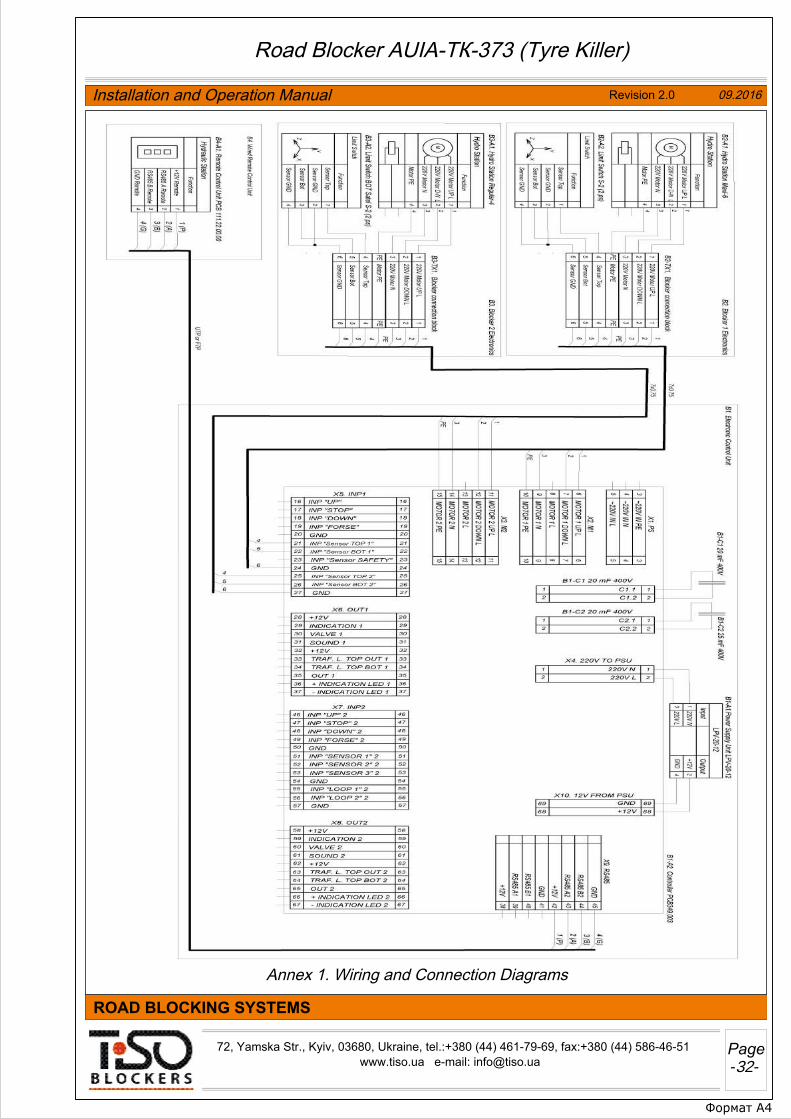
Annex 1. Wiring and Connection Diagrams
Формат А4
72, Yamska Str., Kyiv, 03680, Ukraine, tel.:+380 (44) 461-79-69, fax:+380 (44) 586-46-51 www.tiso.ua e-mail: [email protected]
ROAD BLOCKING SYSTEMS
Road Blocker AUIA-ТК-373 (Tyre Killer)
Installation and Operation Manual Revision 2.0 09.2016
Page-32-