Embed Size (px)
Citation preview

PRO CAL INC. Toll Free 800-323-0966
Toll Free 800-323-0966PRO CAL INC.
Ball Bearing Pilot ModelsThru Shaft Mount - Single Drive CS 1End of Shaft Mount - Single Drive CR 2Thru Shaft Mount - Multiple Drive CM 3End of Shaft Mount - Multiple Drive CE 4
Bronze Bushing Pilot ModelsThru Shaft Mount - Single Drive CU 5End of Shaft Mount - Single Drive CY 6
Hub Start/Stop - Ball Bearing Pilot ModelsThru Shaft Mount - Single Drive XH 7End of Shaft Mount - Single Drive XE 8Thru Shaft Mount - Multiple Drive XM 9End of Shaft Mount - Multiple Drive XB 10
Drive Start/Stop - Ball Bearing Pilot ModelsThru Shaft Mount - Single Drive XP 11End of Shaft Mount - Single Drive XQ 12Thru Shaft Mount - Multiple Drive XT 13End of Shaft Mount - Multiple Drive XJ 14
Series PageCLUTCHES
CLUTCH/BRAKES
Bronze Bushing Pilot ModelsThru Shaft Mount - Single Drive TL 17
TORQUE LIMITERS
Application Information• Torque Ratings/Wear-In • “TL” Adjustment Instructions • Rotary Union Options• Selection Guides • Safety Factors • Rebuild Kits• Installation Instructions • General Notes • Specials
ENGINEERING DATA
PCI is committed to manufacturing a quality product to meet your demandingstandards. Each unit is inspected numerous times during the manufacturing process,assuring you of quality second to none. Every unit is then individually packaged andsealed with the PCI Seal of Excellence.
Seal ofExcellence
Air Set ModelsThru Shaft Mount - Back Mounted BK 15Thru Shaft Mount - Flange Mounted BF 16
BRAKES
In-Line ModelsCoupler MC 18Clutch Housing MH 18Clutch Mechanism MP 19Torque Limiter Mechanism MF 20
MODULAR COMPONENTS
21
TABLE OF CONTENTS
MADE IN THE U.S.A. This catalog is made from recycled paper.
PRO CAL INC. Toll Free 800-323-0966- 1 -
HOW TO ORDER
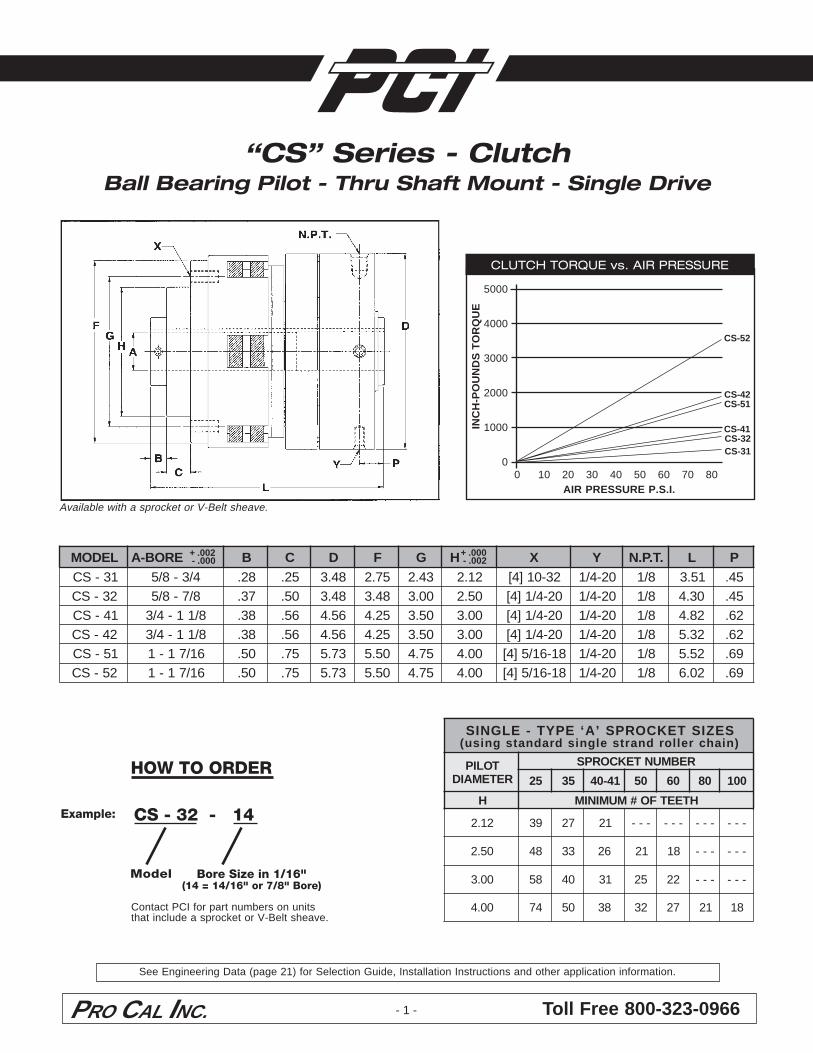
Model Bore Size in 1/16"(14 = 14/16" or 7/8" Bore)
CLUTCH TORQUE vs. AIR PRESSURE
5000
4000
3000
2000
1000
0IN
CH
-PO
UN
DS
TO
RQ
UE
0 10 20 30 40 50 60 70 80AIR PRESSURE P.S.I.
Available with a sprocket or V-Belt sheave.
“CS” Series - ClutchBall Bearing Pilot - Thru Shaft Mount - Single Drive
CS-31CS-32CS-41
CS-51CS-42
CS-52
CS - 32 - 14Example:
Contact PCI for part numbers on unitsthat include a sprocket or V-Belt sheave.
+ .002 - .000
+ .000 - .002LEDOM EROB-A B C D F G H X Y .T.P.N L P
13-SC 4/3-8/5 82. 52. 84.3 57.2 34.2 21.2 23-01]4[ 02-4/1 8/1 15.3 54.23-SC 8/7-8/5 73. 05. 84.3 84.3 00.3 05.2 02-4/1]4[ 02-4/1 8/1 03.4 54.14-SC 8/11-4/3 83. 65. 65.4 52.4 05.3 00.3 02-4/1]4[ 02-4/1 8/1 28.4 26.24-SC 8/11-4/3 83. 65. 65.4 52.4 05.3 00.3 02-4/1]4[ 02-4/1 8/1 23.5 26.15-SC 61/71-1 05. 57. 37.5 05.5 57.4 00.4 81-61/5]4[ 02-4/1 8/1 25.5 96.25-SC 61/71-1 05. 57. 37.5 05.5 57.4 00.4 81-61/5]4[ 02-4/1 8/1 20.6 96.
SEZISTEKCORPS’A‘EPYT-ELGNIS)niahcrellordnartselgnisdradnatsgnisu(
TOLIPRETEMAID
REBMUNTEKCORPS
52 53 14-04 05 06 08 001
H HTEETFO#MUMINIM
21.2 93 72 12 --- --- --- ---
05.2 84 33 62 12 81 --- ---
00.3 85 04 13 52 22 --- ---
00.4 47 05 83 23 72 12 81
See Engineering Data (page 21) for Selection Guide, Installation Instructions and other application information.
Toll Free 800-323-0966PRO CAL INC. - 2 -
Model
LEDOM EROB-A LA B C D F G H X 1L 2L23-RC 8/7-8/5 57.1 83. 05. 84.3 84.3 00.3 05.2 02-4/1]4[ 66.3 77.33-RC 8/7-8/5 00.2 83. 05. 84.3 84.3 00.3 05.2 02-4/1]4[ 00.4 77.24-RC 8/11-4/3 00.2 65. 65. 84.4 52.4 05.3 00.3 02-4/1]4[ 83.4 77.25-RC 61/71-1 05.2 05. 57. 36.5 05.5 57.4 00.4 81-61/5]4[ 78.4 77.35-RC 61/71-1 57.2 05. 57. 36.5 05.5 57.4 00.4 81-61/5]4[ 73.5 77.
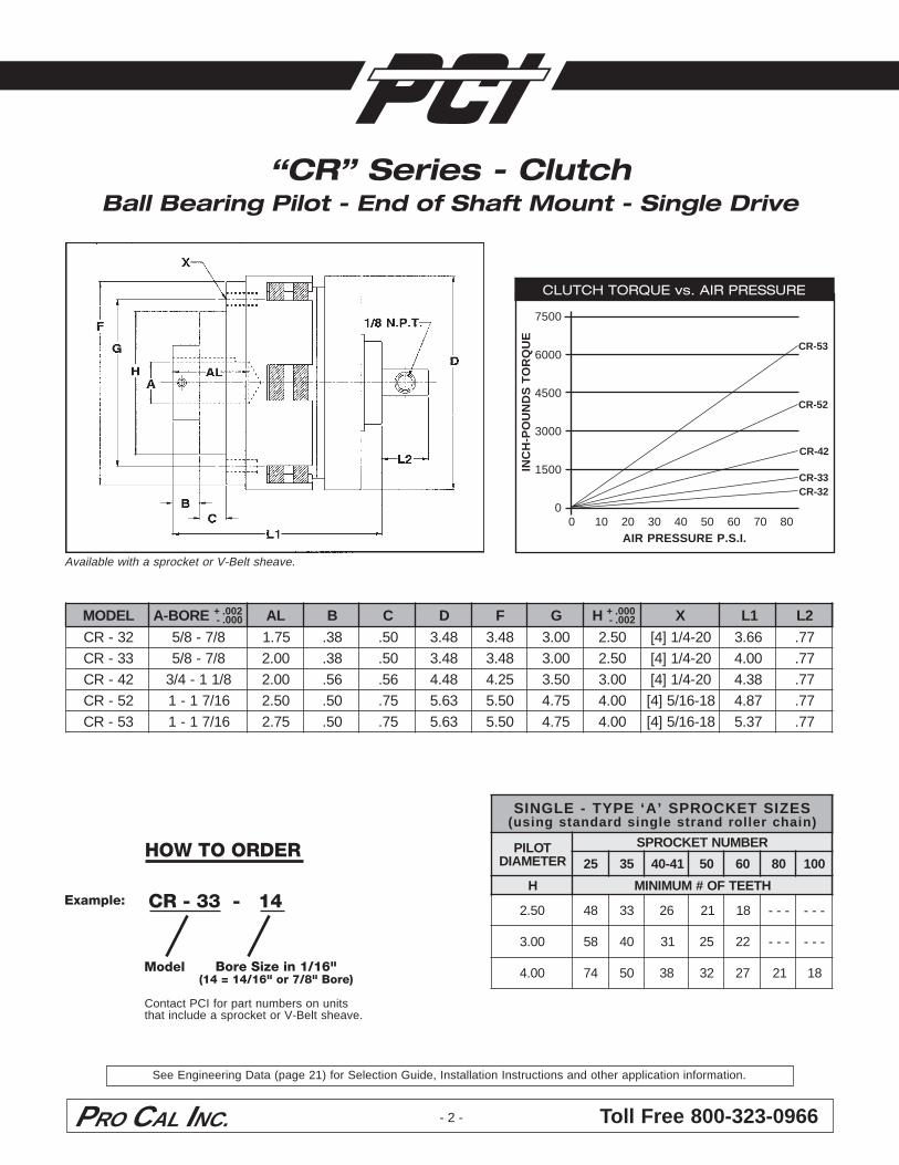
Available with a sprocket or V-Belt sheave.
“CR” Series - ClutchBall Bearing Pilot - End of Shaft Mount - Single Drive
Bore Size in 1/16"(14 = 14/16" or 7/8" Bore)
CLUTCH TORQUE vs. AIR PRESSURE
7500
6000
4500
3000
1500
0
INC
H-P
OU
ND
S T
OR
QU
E0 10 20 30 40 50 60 70 80
AIR PRESSURE P.S.I.
CR-32CR-33
CR-42
CR-52
CR-53
Contact PCI for part numbers on unitsthat include a sprocket or V-Belt sheave.
CR - 33 - 14Example:
+ .002 - .000
+ .000 - .002
SEZISTEKCORPS’A‘EPYT-ELGNIS)niahcrellordnartselgnisdradnatsgnisu(
TOLIPRETEMAID
REBMUNTEKCORPS
52 53 14-04 05 06 08 001
H HTEETFO#MUMINIM
05.2 84 33 62 12 81 --- ---
00.3 85 04 13 52 22 --- ---
00.4 47 05 83 23 72 12 81
HOW TO ORDER
See Engineering Data (page 21) for Selection Guide, Installation Instructions and other application information.
PRO CAL INC. Toll Free 800-323-0966- 3 -
HOW TO ORDER
Model Bore Size in 1/16"(14 = 14/16" or 7/8" Bore)
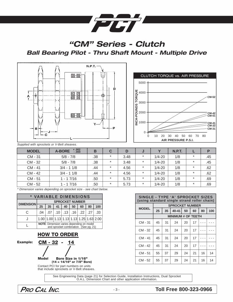
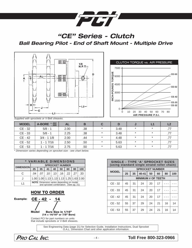
Supplied with sprockets or V-Belt sheaves.
* Dimension varies depending on sprocket size - see chart below.
SNOISNEMIDELBAIRAV*
NOISNEMIDREBMUNTEKCORPS
52 53 14 04 05 06 08 001
C 40. 70. 01. 31. 61. 22. 72. 33.
J 00.1 00.1 31.1 31.1 31.1 52.1 36.1 00.2
L ETON ledomnognidnepedseiravnoisnemiD:)12.gpeeS(.noitanibmoctekcorpsdna
“CM” Series - ClutchBall Bearing Pilot - Thru Shaft Mount - Multiple Drive
CLUTCH TORQUE vs. AIR PRESSURE
5000
4000
3000
2000
1000
0IN
CH
-PO
UN
DS
TO
RQ
UE
0 10 20 30 40 50 60 70 80AIR PRESSURE P.S.I.
CM-31CM-32CM-41
CM-51CM-42
CM-52
CM - 32 - 14Example:
Contact PCI for part numbers on unitsthat include sprockets or V-Belt sheaves.
+ .002 - .000LEDOM EROB-A B C D J Y .T.P.N L P
13-MC 8/7-8/5 83. * 84.3 * 02-4/1 8/1 * 54.23-MC 8/7-8/5 83. * 84.3 * 02-4/1 8/1 * 54.14-MC 8/11-4/3 44. * 65.4 * 02-4/1 8/1 * 26.24-MC 8/11-4/3 44. * 65.4 * 02-4/1 8/1 * 26.15-MC 61/71-1 05. * 37.5 * 02-4/1 8/1 * 96.25-MC 61/71-1 05. * 37.5 * 02-4/1 8/1 * 96.
SEZISTEKCORPS’A‘EPYT-ELGNIS)niahcrellordnartselgnisdradnatsgnisu(
LEDOMREBMUNTEKCORPS
52 53 14-04 05 06 08 001
HTEETFO#MUMINIM
13-MC 54 13 42 02 71 --- ---
23-MC 54 13 42 02 71 --- ---
14-MC 54 13 42 02 71 --- ---
24-MC 54 13 42 02 71 --- ---
15-MC 55 73 92 42 12 61 41
25-MC 55 73 92 42 12 61 41
See Engineering Data (page 21) for Selection Guide, Installation Instructions, Dual SprocketO.A.L. Dimension Chart and other application information.
Toll Free 800-323-0966PRO CAL INC. - 4 -
HOW TO ORDER
Model Bore Size in 1/16"(14 = 14/16" or 7/8" Bore)
Supplied with sprockets or V-Belt sheaves.
* Dimension varies depending on sprocket size - see chart below.
“CE” Series - ClutchBall Bearing Pilot - End of Shaft Mount - Multiple Drive
LEDOM EROB-A LA B C D J 1L 2L23-EC 1-8/5 00.2 83. * 84.3 * * 77.33-EC 1-8/5 52.2 83. * 84.3 * * 77.24-EC 8/11-4/3 00.2 44. * 84.4 * * 77.25-EC 61/71-1 05.2 05. * 36.5 * * 77.35-EC 61/71-1 57.2 05. * 36.5 * * 77.
SEZISTEKCORPS’A‘EPYT-ELGNIS)niahcrellordnartselgnisdradnatsgnisu(
LEDOMREBMUNTEKCORPS
52 53 14-04 05 06 08 001
HTEETFO#MUMINIM
23-EC 54 13 42 02 71 --- ---
33-EC 54 13 42 02 71 --- ---
24-EC 54 13 42 02 71 --- ---
25-EC 55 73 92 42 12 61 41
35-EC 55 73 92 42 12 61 41
CLUTCH TORQUE vs. AIR PRESSURE
7500
6000
4500
3000
1500
0IN
CH
-PO
UN
DS
TO
RQ
UE
0 10 20 30 40 50 60 70 80AIR PRESSURE P.S.I.
CE-32CE-33
CE-42
CE-52
CE-53
CE - 42 - 14Example:
Contact PCI for part numbers on unitsthat include sprockets or V-Belt sheaves.
+ .002 - .000
SNOISNEMIDELBAIRAV*
NOISNEMIDREBMUNTEKCORPS
52 53 14 04 05 06 08 001
C 40. 70. 01. 31. 61. 22. 72. 33.
J 00.1 00.1 31.1 31.1 31.1 52.1 36.1 00.2
1L ETON ledomnognidnepedseiravnoisnemiD:)12.gpeeS(.noitanibmoctekcorpsdna
See Engineering Data (page 21) for Selection Guide, Installation Instructions, Dual SprocketO.A.L. Dimension Chart and other application information.
PRO CAL INC. Toll Free 800-323-0966- 5 -
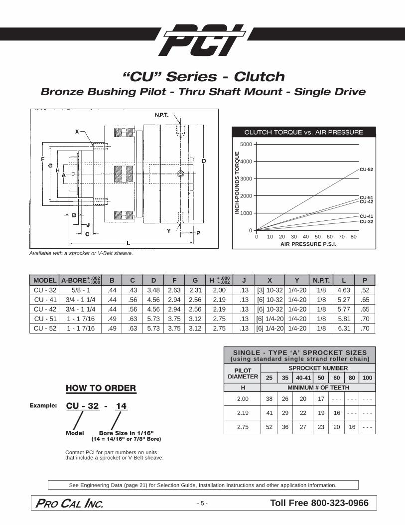
Available with a sprocket or V-Belt sheave.
HOW TO ORDER
Model
“CU” Series - ClutchBronze Bushing Pilot - Thru Shaft Mount - Single Drive
CLUTCH TORQUE vs. AIR PRESSURE
5000
4000
3000
2000
1000
0IN
CH
-PO
UN
DS
TO
RQ
UE
0 10 20 30 40 50 60 70 80AIR PRESSURE P.S.I.
CU-32CU-41
CU-51CU-42
CU-52
Bore Size in 1/16"(14 = 14/16" or 7/8" Bore)
CU - 32 - 14Example:
Contact PCI for part numbers on unitsthat include a sprocket or V-Belt sheave.
+ .002 - .000
+ .000 - .002LEDOM EROB-A B C D F G H J X Y .T.P.N L P
23-UC 1-8/5 44. 34. 84.3 36.2 13.2 00.2 31. 23-01]3[ 02-4/1 8/1 36.4 25.14-UC 4/11-4/3 44. 65. 65.4 49.2 65.2 91.2 31. 23-01]6[ 02-4/1 8/1 72.5 56.24-UC 4/11-4/3 44. 65. 65.4 49.2 65.2 91.2 31. 23-01]6[ 02-4/1 8/1 77.5 56.15-UC 61/71-1 94. 36. 37.5 57.3 21.3 57.2 31. 02-4/1]6[ 02-4/1 8/1 18.5 07.25-UC 61/71-1 94. 36. 37.5 57.3 21.3 57.2 31. 02-4/1]6[ 02-4/1 8/1 13.6 07.
SEZISTEKCORPS’A‘EPYT-ELGNISrellordnartselgnisdradnatsgnisu( )niahc
TOLIPRETEMAID
REBMUNTEKCORPS
52 53 14-04 05 06 08 001
H HTEETFO#MUMINIM
00.2 83 62 02 71 --- --- ---
91.2 14 92 22 91 61 --- ---
57.2 25 63 72 32 02 61 ---
See Engineering Data (page 21) for Selection Guide, Installation Instructions and other application information.
Toll Free 800-323-0966PRO CAL INC. - 6 -
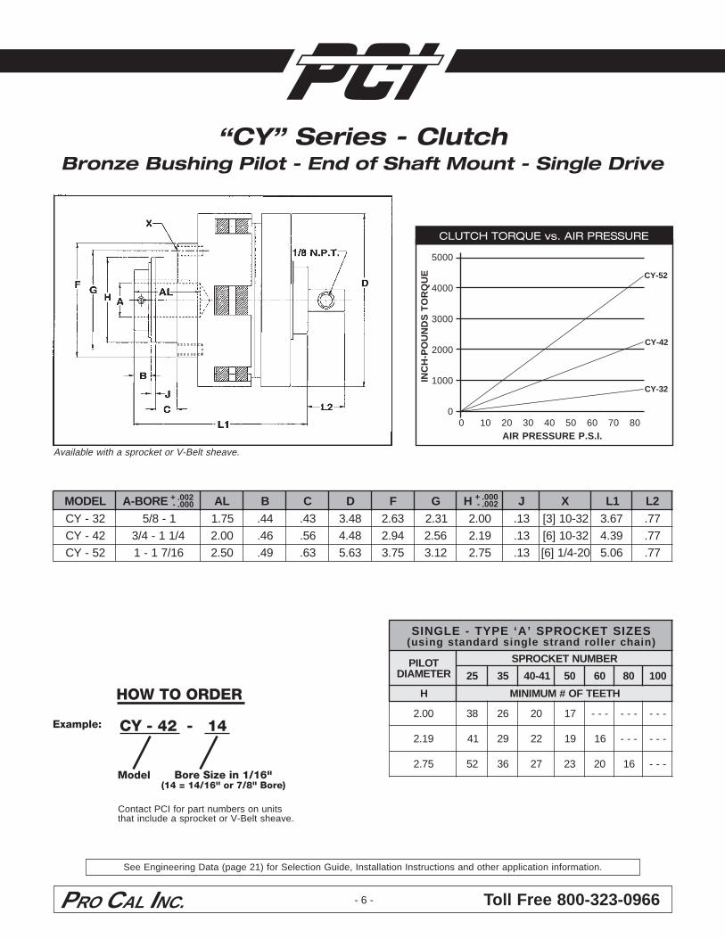
HOW TO ORDER
Model
Available with a sprocket or V-Belt sheave.
“CY” Series - ClutchBronze Bushing Pilot - End of Shaft Mount - Single Drive
CLUTCH TORQUE vs. AIR PRESSURE
5000
4000
3000
2000
1000
0IN
CH
-PO
UN
DS
TO
RQ
UE
0 10 20 30 40 50 60 70 80AIR PRESSURE P.S.I.
CY-32
CY-42
CY-52
Bore Size in 1/16"(14 = 14/16" or 7/8" Bore)
CY - 42 - 14Example:
Contact PCI for part numbers on unitsthat include a sprocket or V-Belt sheave.
+ .002 - .000
+ .000 - .002LEDOM EROB-A LA B C D F G H J X 1L 2L
23-YC 1-8/5 57.1 44. 34. 84.3 36.2 13.2 00.2 31. 23-01]3[ 76.3 77.24-YC 4/11-4/3 00.2 64. 65. 84.4 49.2 65.2 91.2 31. 23-01]6[ 93.4 77.25-YC 61/71-1 05.2 94. 36. 36.5 57.3 21.3 57.2 31. 02-4/1]6[ 60.5 77.
SEZISTEKCORPS’A‘EPYT-ELGNISrellordnartselgnisdradnatsgnisu( )niahc
TOLIPRETEMAID
REBMUNTEKCORPS
52 53 14-04 05 06 08 001
H HTEETFO#MUMINIM
00.2 83 62 02 71 --- --- ---
91.2 14 92 22 91 61 --- ---
57.2 25 63 72 32 02 61 ---
See Engineering Data (page 21) for Selection Guide, Installation Instructions and other application information.
PRO CAL INC. Toll Free 800-323-0966- 7 -
HOW TO ORDER
Model
CLUTCH TORQUE vs. AIR PRESSURE
2500
2000
1500
1000
500
0IN
CH
-PO
UN
DS
TO
RQ
UE
20 30 40 50 60 70 80AIR PRESSURE P.S.I.
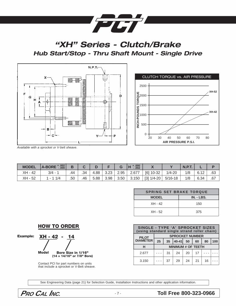
EUQROTEKARBTESGNIRPS
LEDOM .SBL-.NI
24-HX 051
25-HX 573
Available with a sprocket or V-belt sheave.
“XH” Series - Clutch/BrakeHub Start/Stop - Thru Shaft Mount - Single Drive
XH-42
XH-52
Bore Size in 1/16"(14 = 14/16" or 7/8" Bore)
XH - 42 - 14Example:
Contact PCI for part numbers on unitsthat include a sprocket or V-Belt sheave.
+ .002 - .000
+ .000 - .002LEDOM EROB-A B C D F G H X Y .T.P.N L P
24-HX 1-4/3 44. 43. 88.4 32.3 59.2 776.2 23-01]6[ 02-4/1 8/1 21.6 36.25-HX 4/11-1 05. 64. 88.5 89.3 05.3 051.3 02-4/1]3[ 81-61/5 8/1 43.6 76.
SEZISTEKCORPS’A‘EPYT-ELGNIS)niahcrellordnartselgnisdradnatsgnisu(
TOLIPRETEMAID
REBMUNTEKCORPS
52 53 14-04 05 06 08 001
H HTEETFO#MUMINIM
776.2 --- 13 42 02 71 --- ---
051.3 --- 73 92 42 12 61 ---
See Engineering Data (page 21) for Selection Guide, Installation Instructions and other application information.
Toll Free 800-323-0966PRO CAL INC. - 8 -
HOW TO ORDER
Model
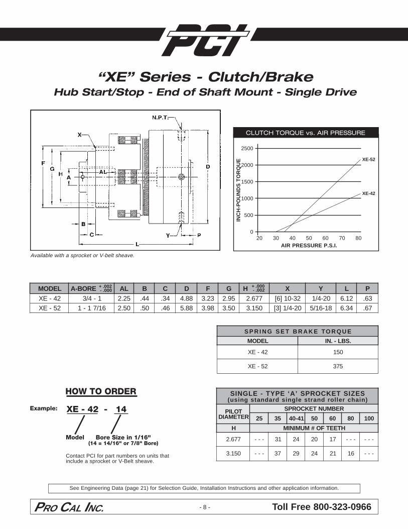
“XE” Series - Clutch/BrakeHub Start/Stop - End of Shaft Mount - Single Drive
CLUTCH TORQUE vs. AIR PRESSURE
2500
2000
1500
1000
500
0IN
CH
-PO
UN
DS
TO
RQ
UE
20 30 40 50 60 70 80AIR PRESSURE P.S.I.
XE-42
XE-52
Bore Size in 1/16"(14 = 14/16" or 7/8" Bore)
XE - 42 - 14Example:
Contact PCI for part numbers on units thatinclude a sprocket or V-Belt sheave.
+ .002 - .000
+ .000 - .002LEDOM EROB-A LA B C D F G H X Y L P
24-EX 1-4/3 52.2 44. 43. 88.4 32.3 59.2 776.2 23-01]6[ 02-4/1 21.6 36.25-EX 61/71-1 05.2 05. 64. 88.5 89.3 05.3 051.3 02-4/1]3[ 81-61/5 43.6 76.
Available with a sprocket or V-belt sheave.
EUQROTEKARBTESGNIRPS
LEDOM .SBL-.NI
24-EX 051
25-EX 573
SEZISTEKCORPS’A‘EPYT-ELGNIS)niahcrellordnartselgnisdradnatsgnisu(
TOLIPRETEMAID
REBMUNTEKCORPS
52 53 14-04 05 06 08 001
H HTEETFO#MUMINIM
776.2 --- 13 42 02 71 --- ---
051.3 --- 73 92 42 12 61 ---
See Engineering Data (page 21) for Selection Guide, Installation Instructions and other application information.
PRO CAL INC. Toll Free 800-323-0966- 9 -
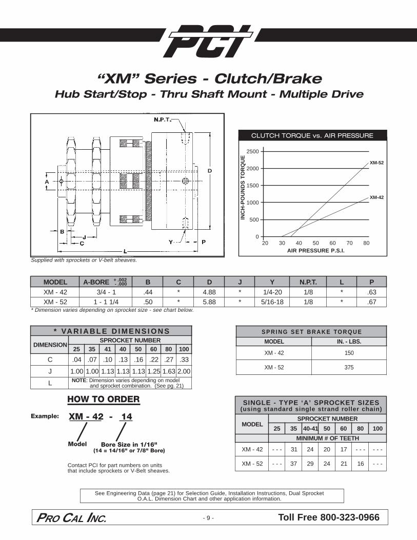
HOW TO ORDER
Model Bore Size in 1/16"(14 = 14/16" or 7/8" Bore)
* Dimension varies depending on sprocket size - see chart below.
“XM” Series - Clutch/BrakeHub Start/Stop - Thru Shaft Mount - Multiple Drive
CLUTCH TORQUE vs. AIR PRESSURE
2500
2000
1500
1000
500
0IN
CH
-PO
UN
DS
TO
RQ
UE
20 30 40 50 60 70 80AIR PRESSURE P.S.I.
XM-42
XM-52
XM - 42 - 14Example:
Contact PCI for part numbers on unitsthat include sprockets or V-Belt sheaves.
A
D
N.P.T.
+ .002 - .000
Supplied with sprockets or V-belt sheaves.
LEDOM EROB-A B C D J Y .T.P.N L P24-MX 1-4/3 44. * 88.4 * 02-4/1 8/1 * 36.25-MX 4/11-1 05. * 88.5 * 81-61/5 8/1 * 76.
SNOISNEMIDELBAIRAV*
NOISNEMIDREBMUNTEKCORPS
52 53 14 04 05 06 08 001
C 40. 70. 01. 31. 61. 22. 72. 33.
J 00.1 00.1 31.1 31.1 31.1 52.1 36.1 00.2
L ETON ledomnognidnepedseiravnoisnemiD:)12.gpeeS(.noitanibmoctekcorpsdna
EUQROTEKARBTESGNIRPS
LEDOM .SBL-.NI
24-MX 051
25-MX 573
SEZISTEKCORPS’A‘EPYT-ELGNIS)niahcrellordnartselgnisdradnatsgnisu(
LEDOMREBMUNTEKCORPS
52 53 14-04 05 06 08 001
HTEETFO#MUMINIM
24-MX --- 13 42 02 71 --- ---
25-MX --- 73 92 42 12 61 ---
See Engineering Data (page 21) for Selection Guide, Installation Instructions, Dual SprocketO.A.L. Dimension Chart and other application information.
Toll Free 800-323-0966PRO CAL INC. - 10 -
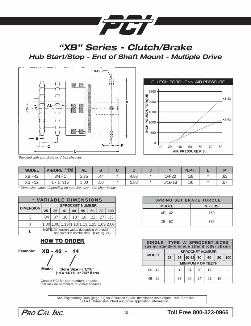
HOW TO ORDER
Model Bore Size in 1/16"(14 = 14/16" or 7/8" Bore)
* Dimension varies depending on sprocket size - see chart below.
“XB” Series - Clutch/BrakeHub Start/Stop - End of Shaft Mount - Multiple Drive
CLUTCH TORQUE vs. AIR PRESSURE
2500
2000
1500
1000
500
0IN
CH
-PO
UN
DS
TO
RQ
UE
20 30 40 50 60 70 80AIR PRESSURE P.S.I.
XB-42
XB-52
XB - 42 - 14Example:
Contact PCI for part numbers on unitsthat include sprockets or V-Belt sheaves.
+ .002 - .000
SNOISNEMIDELBAIRAV*
NOISNEMIDREBMUNTEKCORPS
52 53 14 04 05 06 08 001
C 40. 70. 01. 31. 61. 22. 72. 33.
J 00.1 00.1 31.1 31.1 31.1 52.1 36.1 00.2
L ETON ledomnognidnepedseiravnoisnemiD:)12.gpeeS(.noitanibmoctekcorpsdna
Supplied with sprockets or V-belt sheaves.
LEDOM EROB-A LA B C D J Y .T.P.N L P24-BX 1-4/3 57.2 44. * 88.4 * 02-4/1 8/1 * 36.25-BX 61/71-1 00.3 05. * 88.5 * 81-61/5 8/1 * 76.
EUQROTEKARBTESGNIRPS
LEDOM .SBL-.NI
24-BX 051
25-BX 573
SEZISTEKCORPS’A‘EPYT-ELGNIS)niahcrellordnartselgnisdradnatsgnisu(
LEDOMREBMUNTEKCORPS
52 53 14-04 05 06 08 001
HTEETFO#MUMINIM
24-BX --- 13 42 02 71 --- ---
25-BX --- 73 92 42 12 61 ---
See Engineering Data (page 21) for Selection Guide, Installation Instructions, Dual SprocketO.A.L. Dimension Chart and other application information.
PRO CAL INC. Toll Free 800-323-0966
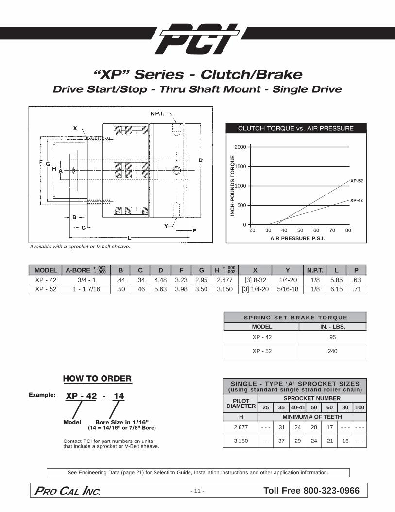
CLUTCH TORQUE vs. AIR PRESSURE
2000
1500
1000
500
0
INC
H-P
OU
ND
S T
OR
QU
E20 30 40 50 60 70 80
AIR PRESSURE P.S.I.
- 11 -
HOW TO ORDER
Model Bore Size in 1/16"(14 = 14/16" or 7/8" Bore)
EUQROTEKARBTESGNIRPS
LEDOM .SBL-.NI
24-PX 59
25-PX 042
“XP” Series - Clutch/BrakeDrive Start/Stop - Thru Shaft Mount - Single Drive
XP-42
XP-52
SEZISTEKCORPS’A‘EPYT-ELGNIS)niahcrellordnartselgnisdradnatsgnisu(
TOLIPRETEMAID
REBMUNTEKCORPS
52 53 14-04 05 06 08 001
H HTEETFO#MUMINIM
776.2 --- 13 42 02 71 --- ---
051.3 --- 73 92 42 12 61 ---
XP - 42 - 14Example:
Contact PCI for part numbers on unitsthat include a sprocket or V-Belt sheave.
L
+ .002 - .000
+ .000 - .002LEDOM EROB-A B C D F G H X Y .T.P.N L P
24-PX 1-4/3 44. 43. 84.4 32.3 59.2 776.2 23-8]3[ 02-4/1 8/1 58.5 36.25-PX 61/71-1 05. 64. 36.5 89.3 05.3 051.3 02-4/1]3[ 81-61/5 8/1 51.6 17.
Available with a sprocket or V-belt sheave.
See Engineering Data (page 21) for Selection Guide, Installation Instructions and other application information.
Toll Free 800-323-0966PRO CAL INC. - 12 -
EUQROTEKARBTESGNIRPS
LEDOM .SBL-.NI
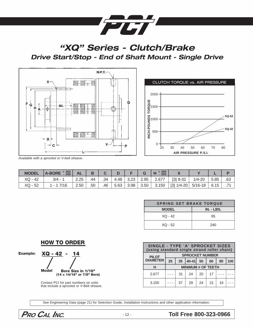
24-QX 59
25-QX 042
Model Bore Size in 1/16"(14 = 14/16" or 7/8" Bore)
“XQ” Series - Clutch/BrakeDrive Start/Stop - End of Shaft Mount - Single Drive
SEZISTEKCORPS’A‘EPYT-ELGNIS)niahcrellordnartselgnisdradnatsgnisu(
TOLIPRETEMAID
REBMUNTEKCORPS
52 53 14-04 05 06 08 001
H HTEETFO#MUMINIM
776.2 --- 13 42 02 71 --- ---
051.3 --- 73 92 42 12 61 ---
CLUTCH TORQUE vs. AIR PRESSURE
2000
1500
1000
500
0
INC
H-P
OU
ND
S T
OR
QU
E20 30 40 50 60 70 80
AIR PRESSURE P.S.I.
XQ-42
XQ-52
XQ - 42 - 14Example:
Contact PCI for part numbers on unitsthat include a sprocket or V-Belt sheave.
+ .002 - .000
+ .000 - .002
Available with a sprocket or V-belt sheave.
LEDOM EROB-A LA B C D F G H X Y L P24-QX 1-4/3 52.2 44. 43. 84.4 32.3 59.2 776.2 23-8]3[ 02-4/1 58.5 36.25-QX 61/71-1 05.2 05. 64. 36.5 89.3 05.3 051.3 02-4/1]3[ 81-61/5 51.6 17.
HOW TO ORDER
See Engineering Data (page 21) for Selection Guide, Installation Instructions and other application information.
PRO CAL INC. Toll Free 800-323-0966- 13 -
EUQROTEKARBTESGNIRPS
LEDOM .SBL-.NI
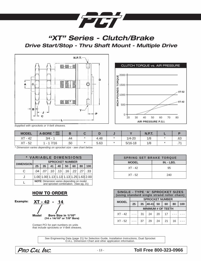
24-TX 59
25-TX 042
SEZISTEKCORPS’A‘EPYT-ELGNIS)niahcrellordnartselgnisdradnatsgnisu(
LEDOMREBMUNTEKCORPS
52 53 14-04 05 06 08 001
HTEETFO#MUMINIM
24-TX --- 13 42 02 71 --- ---
25-TX --- 73 92 42 12 61 ---
Supplied with sprockets or V-belt sheaves.
HOW TO ORDER
Model Bore Size in 1/16"(14 = 14/16" or 7/8" Bore)
* Dimension varies depending on sprocket size - see chart below.
“XT” Series - Clutch/BrakeDrive Start/Stop - Thru Shaft Mount - Multiple Drive
CLUTCH TORQUE vs. AIR PRESSURE
2000
1500
1000
500
0IN
CH
-PO
UN
DS
TO
RQ
UE
20 30 40 50 60 70 80
AIR PRESSURE P.S.I.
XT-42
XT-52
XT - 42 - 14Example:
Contact PCI for part numbers on unitsthat include sprockets or V-Belt sheaves.
+ .002 - .000
SNOISNEMIDELBAIRAV*
NOISNEMIDREBMUNTEKCORPS
52 53 14 04 05 06 08 001
C 40. 70. 01. 31. 61. 22. 72. 33.
J 00.1 00.1 31.1 31.1 31.1 52.1 36.1 00.2
L ETON ledomnognidnepedseiravnoisnemiD:)12.gpeeS(.noitanibmoctekcorpsdna
LEDOM EROB-A B C D J Y .T.P.N L P24-TX 1-4/3 44. * 84.4 * 02-4/1 8/1 * 36.25-TX 61/71-1 05. * 36.5 * 81-61/5 8/1 * 17.
See Engineering Data (page 21) for Selection Guide, Installation Instructions, Dual SprocketO.A.L. Dimension Chart and other application information.
Toll Free 800-323-0966PRO CAL INC. - 14 -
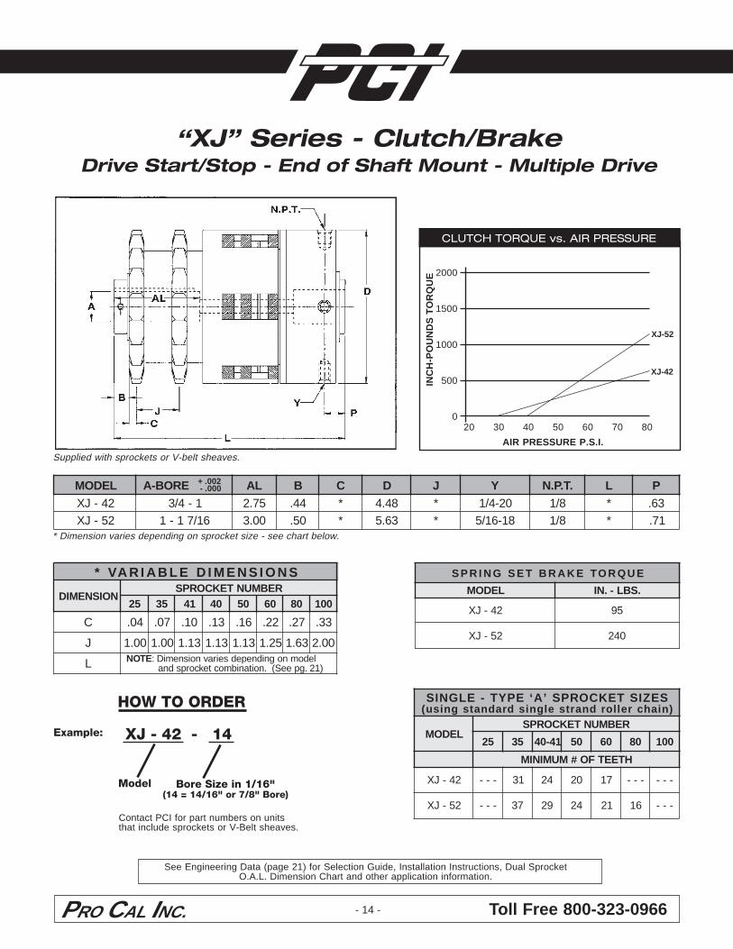
Supplied with sprockets or V-belt sheaves.
* Dimension varies depending on sprocket size - see chart below.
HOW TO ORDER
Model Bore Size in 1/16"(14 = 14/16" or 7/8" Bore)
EUQROTEKARBTESGNIRPS
LEDOM .SBL-.NI
24-JX 59
25-JX 042
SEZISTEKCORPS’A‘EPYT-ELGNIS)niahcrellordnartselgnisdradnatsgnisu(
LEDOMREBMUNTEKCORPS
52 53 14-04 05 06 08 001
HTEETFO#MUMINIM
24-JX --- 13 42 02 71 --- ---
25-JX --- 73 92 42 12 61 ---
“XJ” Series - Clutch/BrakeDrive Start/Stop - End of Shaft Mount - Multiple Drive
CLUTCH TORQUE vs. AIR PRESSURE
2000
1500
1000
500
0IN
CH
-PO
UN
DS
TO
RQ
UE
20 30 40 50 60 70 80
AIR PRESSURE P.S.I.
XJ-42
XJ-52
XJ - 42 - 14Example:
Contact PCI for part numbers on unitsthat include sprockets or V-Belt sheaves.
+ .002 - .000
SNOISNEMIDELBAIRAV*
NOISNEMIDREBMUNTEKCORPS
52 53 14 04 05 06 08 001
C 40. 70. 01. 31. 61. 22. 72. 33.
J 00.1 00.1 31.1 31.1 31.1 52.1 36.1 00.2
L ETON ledomnognidnepedseiravnoisnemiD:)12.gpeeS(.noitanibmoctekcorpsdna
LEDOM EROB-A LA B C D J Y .T.P.N L P24-JX 1-4/3 57.2 44. * 84.4 * 02-4/1 8/1 * 36.25-JX 61/71-1 00.3 05. * 36.5 * 81-61/5 8/1 * 17.
See Engineering Data (page 21) for Selection Guide, Installation Instructions, Dual SprocketO.A.L. Dimension Chart and other application information.
PRO CAL INC. Toll Free 800-323-0966- 15 -
HOW TO ORDER
Model Bore Size in 1/16"(14 = 14/16" or 7/8" Bore)
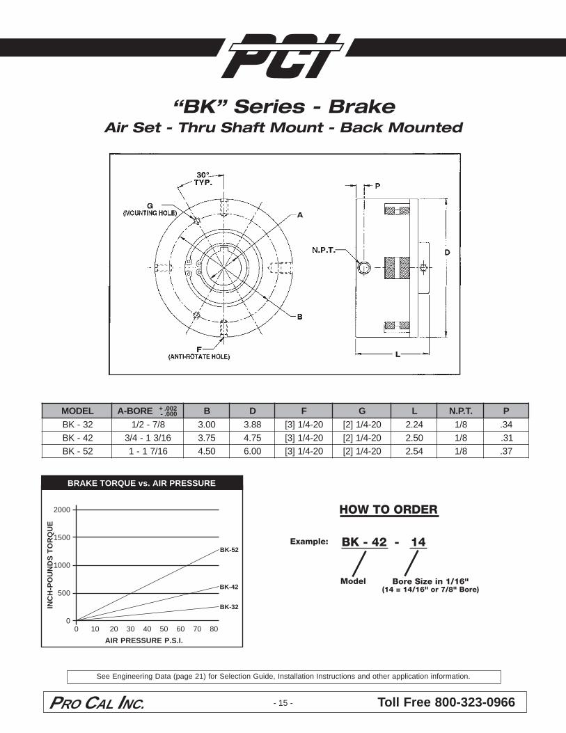
“BK” Series - BrakeAir Set - Thru Shaft Mount - Back Mounted
BRAKE TORQUE vs. AIR PRESSURE
2000
1500
1000
500
0
INC
H-P
OU
ND
S T
OR
QU
E
0 10 20 30 40 50 60 70 80
AIR PRESSURE P.S.I.
BK-42
BK-52
BK-32
BK - 42 - 14Example:
+ .002 - .000LEDOM EROB-A B D F G L .T.P.N P
23-KB 8/7-2/1 00.3 88.3 02-4/1]3[ 02-4/1]2[ 42.2 8/1 43.24-KB 61/31-4/3 57.3 57.4 02-4/1]3[ 02-4/1]2[ 05.2 8/1 13.25-KB 61/71-1 05.4 00.6 02-4/1]3[ 02-4/1]2[ 45.2 8/1 73.
See Engineering Data (page 21) for Selection Guide, Installation Instructions and other application information.
Toll Free 800-323-0966PRO CAL INC.
HOW TO ORDER
Model Bore Size in 1/16"(14 = 14/16" or 7/8" Bore)
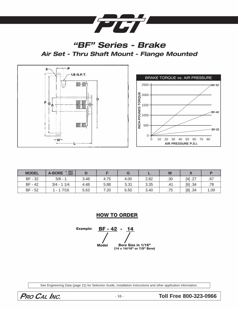
“BF” Series - BrakeAir Set - Thru Shaft Mount - Flange Mounted
BRAKE TORQUE vs. AIR PRESSURE
2500
2000
1500
1000
500
0IN
CH
-PO
UN
DS
TO
RQ
UE
0 10 20 30 40 50 60 70 80AIR PRESSURE P.S.I.
BF-32
BF-42
BF-52
BF - 42 - 14Example:
- 16 -
+ .002 - .000LEDOM EROB-A D F G L W X P
23-FB 1-8/5 84.3 57.4 00.4 28.2 03. 72.]4[ 76.24-FB 4/11-4/3 84.4 88.5 13.5 53.3 14. 43.]6[ 87.25-FB 61/71-1 36.5 02.7 05.6 04.3 57. 43.]8[ 90.1
See Engineering Data (page 21) for Selection Guide, Installation Instructions and other application information.
PRO CAL INC. Toll Free 800-323-0966
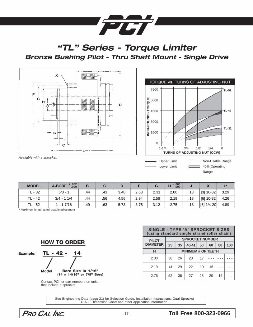
“TL” Series - Torque LimiterBronze Bushing Pilot - Thru Shaft Mount - Single Drive
- 17 -
+ .002 - .000
Contact PCI for part numbers on unitsthat include a sprocket.
Available with a sprocket.
TORQUE vs. TURNS OF ADJUSTING NUT
7500
6000
4500
3000
1500
0IN
CH
-PO
UN
DS
TO
RQ
UE
1-1/4 1 3/4 1/2 1/4 0TURNS OF ADJUSTING NUT (CCW)
TL-32
TL-42
TL-52
Upper Limit
Lower Limit
SEZISTEKCORPS’A‘EPYT-ELGNISrellordnartselgnisdradnatsgnisu( )niahc
TOLIPRETEMAID
REBMUNTEKCORPS
52 53 14-04 05 06 08 001
H HTEETFO#MUMINIM
00.2 83 62 02 71 --- --- ---
91.2 14 92 22 91 61 --- ---
57.2 25 63 72 32 02 61 ---
+ .000 - .002
* Maximum length at full usable adjustment
Non-Usable Range
40% Operating
Range
Model Bore Size in 1/16"(14 = 14/16" or 7/8" Bore)
TL - 42 - 14Example:
HOW TO ORDER
See Engineering Data (page 21) for Selection Guide, Installation Instructions, Dual SprocketO.A.L. Dimension Chart and other application information.
MODEL A-BORE B C D F G H J X L*
TL - 32 5/8 - 1 .44 .43 3.48 2.63 2.31 2.00 .13 [3] 10-32 3.29
TL - 42 3/4 - 1 1/4 .44 .56 4.56 2.94 2.56 2.19 .13 [6] 10-32 4.26
TL - 52 1 - 1 7/16 .49 .63 5.73 3.75 3.12 2.75 .13 [6] 1/4-20 4.89
Toll Free 800-323-0966PRO CAL INC. - 18 -
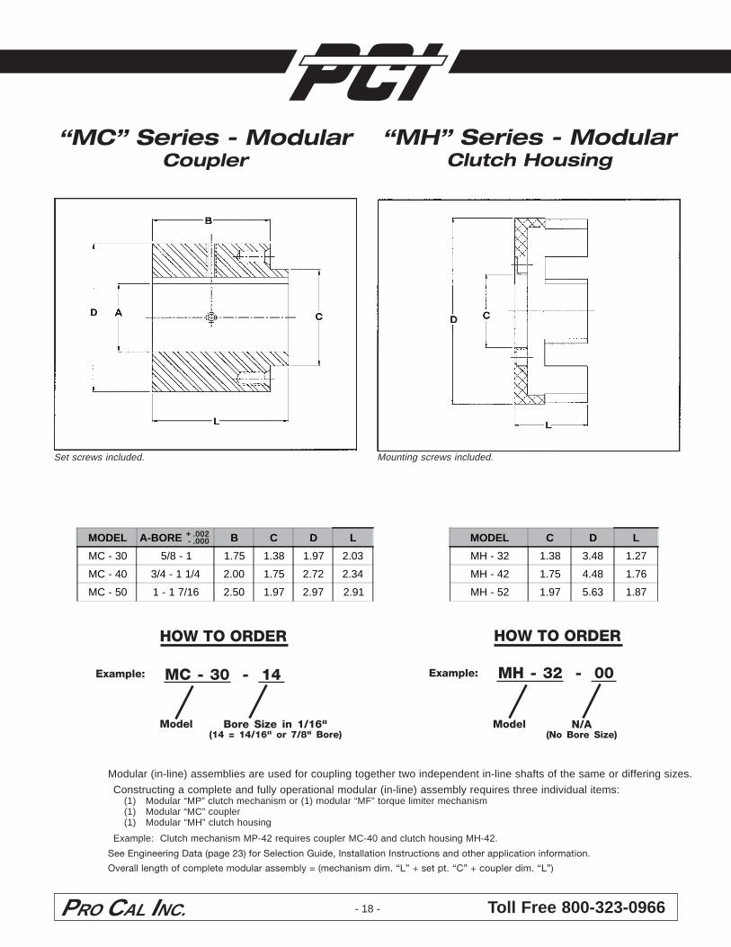
“MH” Series - ModularClutch Housing
Mounting screws included.
Model N/A(No Bore Size)
MH - 32 - 00Example:
“MC” Series - ModularCoupler
+ .002 - .000
Set screws included.
Model Bore Size in 1/16"(14 = 14/16" or 7/8" Bore)
MC - 30 - 14Example:
HOW TO ORDER HOW TO ORDER
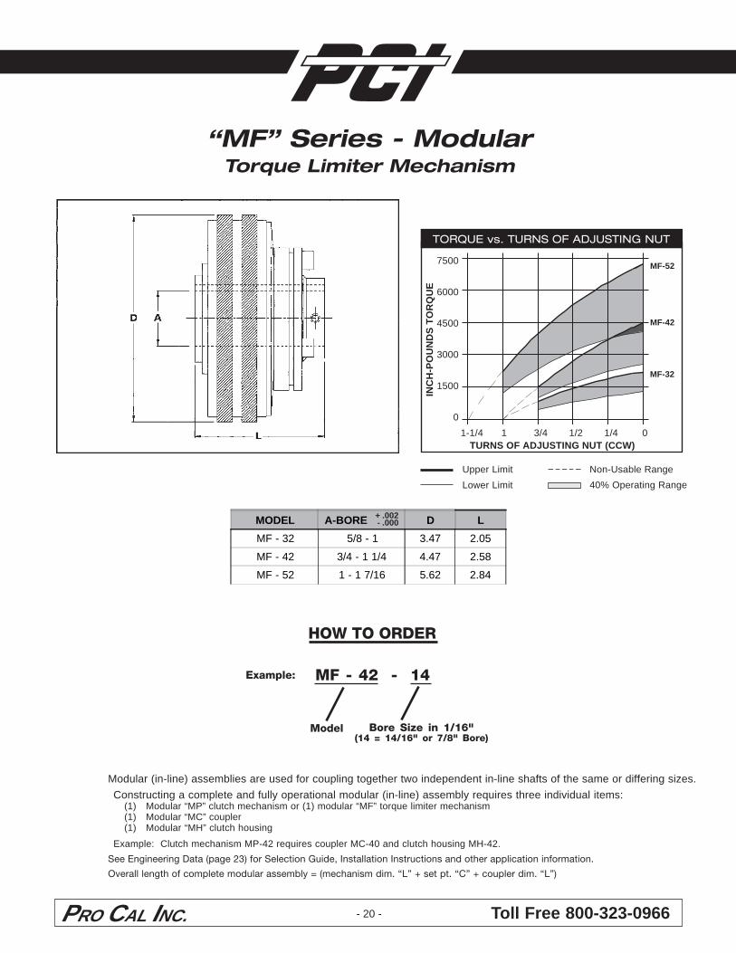
Modular (in-line) assemblies are used for coupling together two independent in-line shafts of the same or differing sizes.
Constructing a complete and fully operational modular (in-line) assembly requires three individual items:(1) Modular “MP” clutch mechanism or (1) modular “MF” torque limiter mechanism(1) Modular “MC” coupler(1) Modular “MH” clutch housing
Example: Clutch mechanism MP-42 requires coupler MC-40 and clutch housing MH-42.
See Engineering Data (page 23) for Selection Guide, Installation Instructions and other application information.
Overall length of complete modular assembly = (mechanism dim. “L” + set pt. “C” + coupler dim. “L”)
MODEL A-BORE B C D L
MC - 30 5/8 - 1 1.75 1.38 1.97 2.03
MC - 40 3/4 - 1 1/4 2.00 1.75 2.72 2.34
MC - 50 1 - 1 7/16 2.50 1.97 2.97 2.91
MODEL C D L
MH - 32 1.38 3.48 1.27
MH - 42 1.75 4.48 1.76
MH - 52 1.97 5.63 1.87
PRO CAL INC. Toll Free 800-323-0966
CLUTCH TORQUE vs. AIR PRESSURE
5000
4000
3000
2000
1000
0IN
CH
-PO
UN
DS
TO
RQ
UE
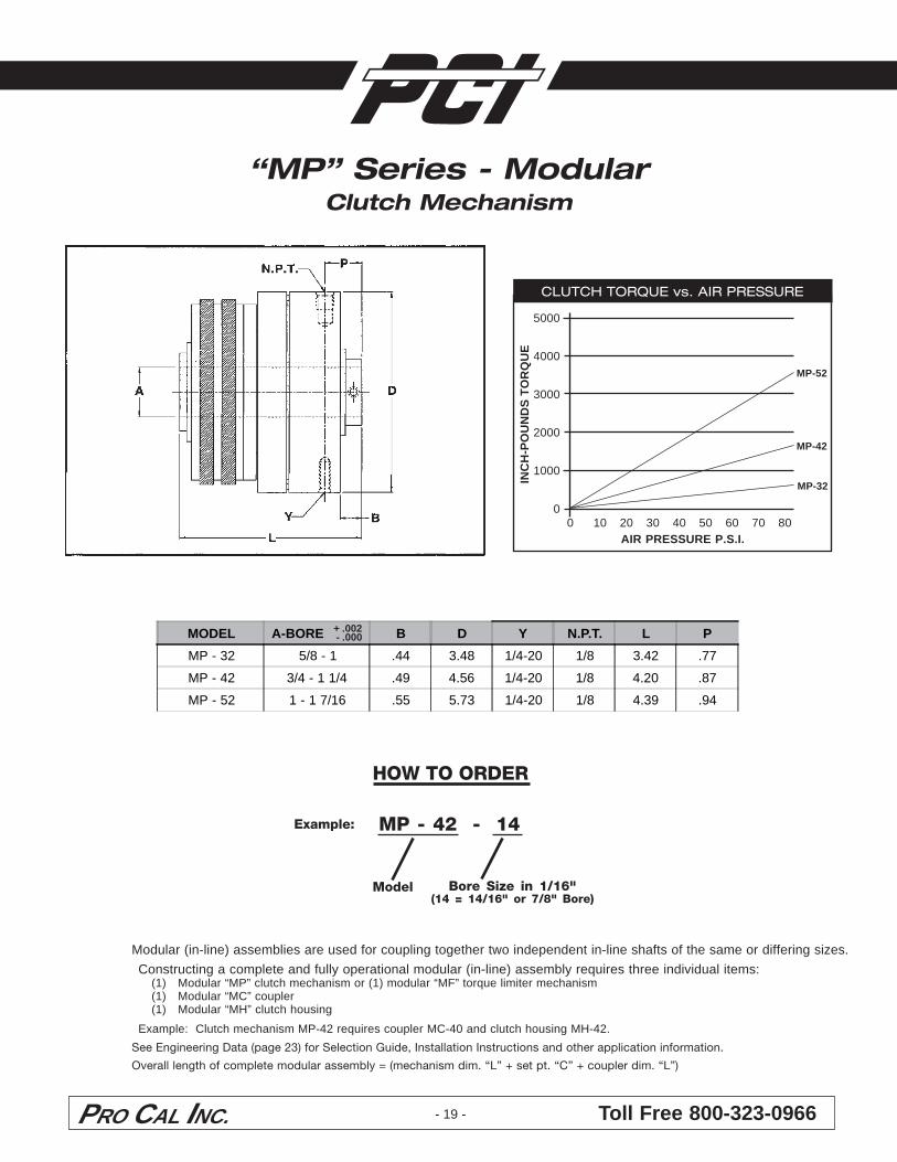
0 10 20 30 40 50 60 70 80AIR PRESSURE P.S.I.
MP-32
MP-42
MP-52
- 19 -
+ .002 - .000
“MP” Series - ModularClutch Mechanism
Model Bore Size in 1/16"(14 = 14/16" or 7/8" Bore)
MP - 42 - 14Example:
HOW TO ORDER
Modular (in-line) assemblies are used for coupling together two independent in-line shafts of the same or differing sizes.
Constructing a complete and fully operational modular (in-line) assembly requires three individual items:(1) Modular “MP” clutch mechanism or (1) modular “MF” torque limiter mechanism(1) Modular “MC” coupler(1) Modular “MH” clutch housing
Example: Clutch mechanism MP-42 requires coupler MC-40 and clutch housing MH-42.
See Engineering Data (page 23) for Selection Guide, Installation Instructions and other application information.
Overall length of complete modular assembly = (mechanism dim. “L” + set pt. “C” + coupler dim. “L”)
MODEL A-BORE B D Y N.P.T. L P
MP - 32 5/8 - 1 .44 3.48 1/4-20 1/8 3.42 .77
MP - 42 3/4 - 1 1/4 .49 4.56 1/4-20 1/8 4.20 .87
MP - 52 1 - 1 7/16 .55 5.73 1/4-20 1/8 4.39 .94
Toll Free 800-323-0966PRO CAL INC.
“MF” Series - ModularTorque Limiter Mechanism
- 20 -
+ .002 - .000
Model Bore Size in 1/16"(14 = 14/16" or 7/8" Bore)
MF - 42 - 14Example:
Upper Limit
Lower Limit
Non-Usable Range
40% Operating Range
TORQUE vs. TURNS OF ADJUSTING NUT
7500
6000
4500
3000
1500
0IN
CH
-PO
UN
DS
TO
RQ
UE
1-1/4 1 3/4 1/2 1/4 0TURNS OF ADJUSTING NUT (CCW)
MF-32
MF-42
MF-52
HOW TO ORDER
Modular (in-line) assemblies are used for coupling together two independent in-line shafts of the same or differing sizes.
Constructing a complete and fully operational modular (in-line) assembly requires three individual items:(1) Modular “MP” clutch mechanism or (1) modular “MF” torque limiter mechanism(1) Modular “MC” coupler(1) Modular “MH” clutch housing
Example: Clutch mechanism MP-42 requires coupler MC-40 and clutch housing MH-42.
See Engineering Data (page 23) for Selection Guide, Installation Instructions and other application information.
Overall length of complete modular assembly = (mechanism dim. “L” + set pt. “C” + coupler dim. “L”)
MODEL A-BORE D L
MF - 32 5/8 - 1 3.47 2.05
MF - 42 3/4 - 1 1/4 4.47 2.58
MF - 52 1 - 1 7/16 5.62 2.84
PRO CAL INC. Toll Free 800-323-0966
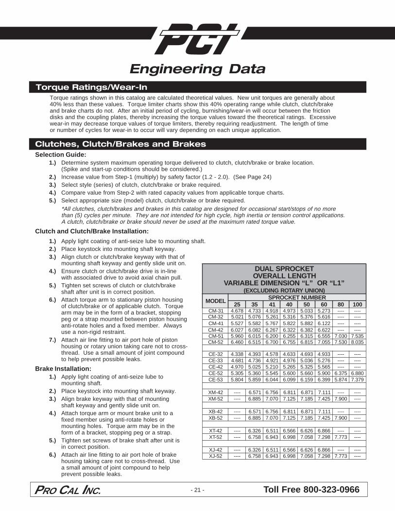
Engineering DataTorque Ratings/Wear-In
Torque ratings shown in this catalog are calculated theoretical values. New unit torques are generally about40% less than these values. Torque limiter charts show this 40% operating range while clutch, clutch/brakeand brake charts do not. After an initial period of cycling, burnishing/wear-in will occur between the frictiondisks and the coupling plates, thereby increasing the torque values toward the theoretical ratings. Excessivewear-in may decrease torque values of torque limiters, thereby requiring readjustment. The length of timeor number of cycles for wear-in to occur will vary depending on each unique application.
- 21 -
Clutches, Clutch/Brakes and BrakesSelection Guide:
1.) Determine system maximum operating torque delivered to clutch, clutch/brake or brake location.(Spike and start-up conditions should be considered.)
2.) Increase value from Step-1 (multiply) by safety factor (1.2 - 2.0). (See Page 24)3.) Select style (series) of clutch, clutch/brake or brake required.4.) Compare value from Step-2 with rated capacity values from applicable torque charts.5.) Select appropriate size (model) clutch, clutch/brake or brake required.
*All clutches, clutch/brakes and brakes in this catalog are designed for occasional start/stops of no morethan (5) cycles per minute. They are not intended for high cycle, high inertia or tension control applications.A clutch, clutch/brake or brake should never be used at the maximum rated torque value.
Clutch and Clutch/Brake Installation:
1.) Apply light coating of anti-seize lube to mounting shaft.2.) Place keystock into mounting shaft keyway.3.) Align clutch or clutch/brake keyway with that of
mounting shaft keyway and gently slide unit on.4.) Ensure clutch or clutch/brake drive is in-line
with associated drive to avoid axial chain pull.5.) Tighten set screws of clutch or clutch/brake
shaft after unit is in correct position.6.) Attach torque arm to stationary piston housing
of clutch/brake or of applicable clutch. Torquearm may be in the form of a bracket, stoppingpeg or a strap mounted between piston housinganti-rotate holes and a fixed member. Alwaysuse a non-rigid restraint.
7.) Attach air line fitting to air port hole of pistonhousing or rotary union taking care not to cross-thread. Use a small amount of joint compoundto help prevent possible leaks.
Brake Installation:1.) Apply light coating of anti-seize lube to
mounting shaft.2.) Place keystock into mounting shaft keyway.3.) Align brake keyway with that of mounting
shaft keyway and gently slide unit on.4.) Attach torque arm or mount brake unit to a
fixed member using anti-rotate holes ormounting holes. Torque arm may be in theform of a bracket, stopping peg or a strap.
5.) Tighten set screws of brake shaft after unit isin correct position.
6.) Attach air line fitting to air port hole of brakehousing taking care not to cross-thread. Usea small amount of joint compound to helpprevent possible leaks.
TEKCORPSLAUDHTGNELLLAREVO”L“NOISNEMIDELBAIRAV RO “ 1L ”
)NOINUYRATORGNIDULCXE(
LEDOMREBMUNTEKCORPS
52 53 14 04 05 06 08 00113-MC 876.4 337.4 819.4 379.4 330.5 372.5 ---- ----23-MC 120.5 670.5 162.5 613.5 673.5 616.5 ---- ----14-MC 725.5 285.5 767.5 228.5 288.5 221.6 ---- ----24-MC 720.6 280.6 762.6 223.6 283.6 226.6 ---- ----15-MC 069.5 510.6 002.6 552.6 513.6 555.6 030.7 535.725-MC 064.6 515.6 007.6 557.6 518.6 550.7 035.7 530.8
23-EC 833.4 393.4 875.4 336.4 396.4 339.4 ---- ----33-EC 186.4 637.4 129.4 679.4 630.5 672.5 ---- ----24-EC 079.4 520.5 012.5 562.5 523.5 565.5 ---- ----25-EC 503.5 063.5 545.5 006.5 066.5 009.5 573.6 088.635-EC 408.5 958.5 440.6 990.6 951.6 993.6 478.5 973.7
24-MX ---- 175.6 657.6 118.6 178.6 111.7 ---- ----25-MX ---- 588.6 070.7 521.7 581.7 524.7 009.7 ----
24-BX ---- 175.6 657.6 118.6 178.6 111.7 ---- ----25-BX ---- 588.6 070.7 521.7 581.7 524.7 009.7 ----
24-TX ---- 623.6 115.6 665.6 626.6 668.6 ---- ----25-TX ---- 857.6 349.6 899.6 850.7 892.7 377.7 ----
24-JX ---- 623.6 115.6 665.6 626.6 668.6 ---- ----25-JX ---- 857.6 349.6 899.6 850.7 892.7 377.7 ----
Toll Free 800-323-0966PRO CAL INC.
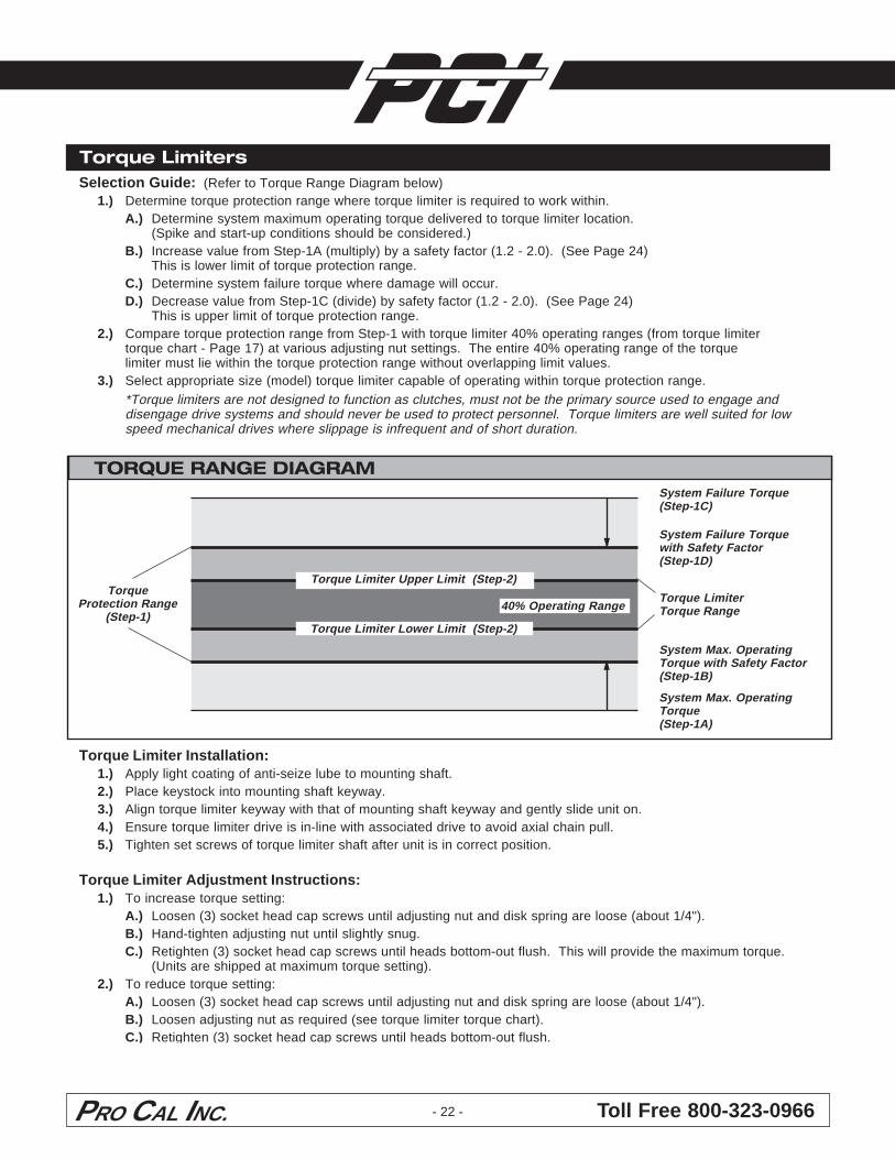
Selection Guide: (Refer to Torque Range Diagram below)1.) Determine torque protection range where torque limiter is required to work within.
A.) Determine system maximum operating torque delivered to torque limiter location.(Spike and start-up conditions should be considered.)
B.) Increase value from Step-1A (multiply) by a safety factor (1.2 - 2.0). (See Page 24)This is lower limit of torque protection range.
C.) Determine system failure torque where damage will occur.D.) Decrease value from Step-1C (divide) by safety factor (1.2 - 2.0). (See Page 24)
This is upper limit of torque protection range.2.) Compare torque protection range from Step-1 with torque limiter 40% operating ranges (from torque limiter
torque chart - Page 17) at various adjusting nut settings. The entire 40% operating range of the torquelimiter must lie within the torque protection range without overlapping limit values.
3.) Select appropriate size (model) torque limiter capable of operating within torque protection range.*Torque limiters are not designed to function as clutches, must not be the primary source used to engage anddisengage drive systems and should never be used to protect personnel. Torque limiters are well suited for lowspeed mechanical drives where slippage is infrequent and of short duration.
TORQUE RANGE DIAGRAMSystem Failure Torque(Step-1C)
System Failure Torquewith Safety Factor(Step-1D)
System Max. OperatingTorque with Safety Factor(Step-1B)
System Max. OperatingTorque(Step-1A)
Torque LimiterTorque Range
TorqueProtection Range
(Step-1)
1234567890123456789012345678901212345678901123456789012345678901234567890121234567890112345678901234567890123456789012123456789011234567890123456789012345678901212345678901Torque Limiter Upper Limit (Step-2)
123456789012345678901234567890121234567890112345678901234567890123456789012123456789011234567890123456789012345678901212345678901Torque Limiter Lower Limit (Step-2)
12345678901234567890123412345678901234567890123412345678901234567890123440% Operating Range
Torque Limiters
Torque Limiter Installation:1.) Apply light coating of anti-seize lube to mounting shaft.2.) Place keystock into mounting shaft keyway.3.) Align torque limiter keyway with that of mounting shaft keyway and gently slide unit on.4.) Ensure torque limiter drive is in-line with associated drive to avoid axial chain pull.5.) Tighten set screws of torque limiter shaft after unit is in correct position.
Torque Limiter Adjustment Instructions:1.) To increase torque setting:
A.) Loosen (3) socket head cap screws until adjusting nut and disk spring are loose (about 1/4").B.) Hand-tighten adjusting nut until slightly snug.C.) Retighten (3) socket head cap screws until heads bottom-out flush. This will provide the maximum torque.
(Units are shipped at maximum torque setting).2.) To reduce torque setting:
A.) Loosen (3) socket head cap screws until adjusting nut and disk spring are loose (about 1/4").B.) Loosen adjusting nut as required (see torque limiter torque chart).C.) Retighten (3) socket head cap screws until heads bottom-out flush.
- 22 -
PRO CAL INC. Toll Free 800-323-0966
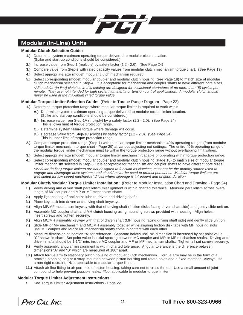
Modular (In-Line) Units
- 23 -
Modular Clutch Selection Guide:1.) Determine system maximum operating torque delivered to modular clutch location.
(Spike and start-up conditions should be considered.)2.) Increase value from Step-1 (multiply) by safety factor (1.2 - 2.0). (See Page 24)3.) Compare value from Step-2 with rated capacity values from modular clutch mechanism torque chart. (See Page 19)4.) Select appropriate size (model) modular clutch mechanism required.5.) Select corresponding (model) modular coupler and modular clutch housing (See Page 18) to match size of modular
clutch mechanism selected in Step-4. It is acceptable for mechanism and coupler shafts to have different bore sizes.*All modular (in-line) clutches in this catalog are designed for occasional start/stops of no more than (5) cycles perminute. They are not intended for high cycle, high inertia or tension control applications. A modular clutch shouldnever be used at the maximum rated torque value.
Modular Torque Limiter Selection Guide: (Refer to Torque Range Diagram - Page 22)1.) Determine torque protection range where modular torque limiter is required to work within.
A.) Determine system maximum operating torque delivered to modular torque limiter location.(Spike and start-up conditions should be considered.)
B.) Increase value from Step-1A (multiply) by a safety factor (1.2 - 2.0). (See Page 24)This is lower limit of torque protection range.
C.) Determine system failure torque where damage will occur.D.) Decrease value from Step-1C (divide) by safety factor (1.2 - 2.0). (See Page 24)
This is upper limit of torque protection range.2.) Compare torque protection range (Step-1) with modular torque limiter mechanism 40% operating ranges (from modular
torque limiter mechanism torque chart - Page 20) at various adjusting nut settings. The entire 40% operating range ofthe modular torque limiter mechanism must lie within the torque protection range without overlapping limit values.
3.) Select appropriate size (model) modular torque limiter mechanism capable of operating within torque protection range.4.) Select corresponding (model) modular coupler and modular clutch housing (Page 18) to match size of modular torque
limiter mechanism selected in Step-3. It is acceptable for mechanism and coupler shafts to have different bore sizes.*Modular (in-line) torque limiters are not designed to function as clutches, must not be the primary source used toengage and disengage drive systems and should never be used to protect personnel. Modular torque limiters arewell suited for low speed mechanical drives where slippage is infrequent and of short duration.
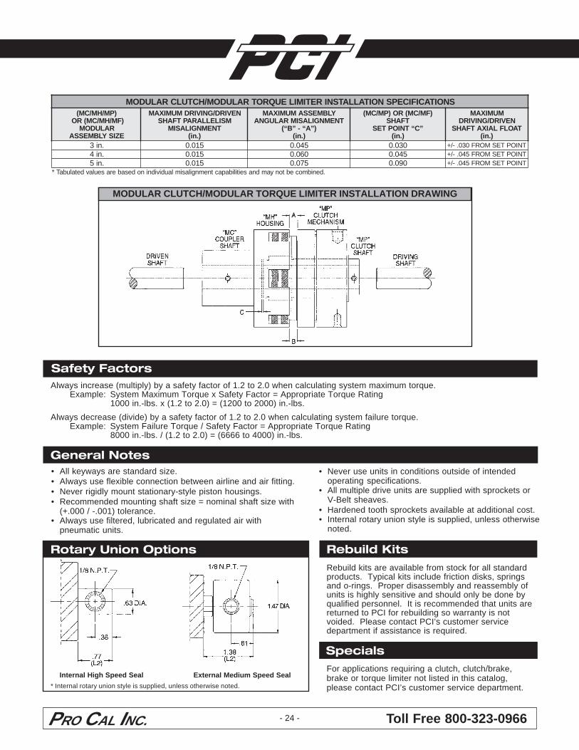
Modular Clutch/Modular Torque Limiter Installation: (Refer to Modular Installation Chart and Drawing - Page 24)1.) Verify driving and driven shaft parallelism misalignment is within charted tolerance. Measure parallelism across overall
length of MC coupler and MP or MF mechanism shafts.2.) Apply light coating of anti-seize lube to driven and driving shafts.3.) Place keystock into driven and driving shaft keyways.4.) Align MP/MF mechanism keyway with that of driving shaft (friction disks facing driven shaft side) and gently slide unit on.5.) Assemble MC coupler shaft and MH clutch housing using mounting screws provided with housing. Align holes,
insert screws and tighten securely.6.) Align MC/MH assembly keyway with that of driven shaft (MH housing facing driving shaft side) and gently slide unit on.7.) Slide MP or MF mechanism and MC/MH assembly together while aligning friction disk tabs with MH housing slots
until MC coupler and MP or MF mechanism shafts come in contact with each other.8.) Measure dimension at location “A” for reference. Separate halves until “A”-dimension is increased by set point value
“C” shown in chart. Set point value is initial spacing between MC coupler and MP or MF mechanism shafts. Driving anddriven shafts should be 1-1/2" min. inside MC coupler and MP or MF mechanism shafts. Tighten all set screws securely.
9.) Verify assembly angular misalignment is within charted tolerance. Angular tolerance is the difference betweendimensions “A” and “B” which are measured at 180° apart.
10.) Attach torque arm to stationary piston housing of modular clutch mechanism. Torque arm may be in the form of abracket, stopping peg or a strap mounted between piston housing anti-rotate holes and a fixed member. Always usea non-rigid restraint. *Not applicable to modular torque limiter.
11.) Attach air line fitting to air port hole of piston housing, taking care not to cross-thread. Use a small amount of jointcompound to help prevent possible leaks. *Not applicable to modular torque limiter.
Modular Torque Limiter Adjustment Instructions:• See Torque Limiter Adjustment Instructions - Page 22.
Toll Free 800-323-0966PRO CAL INC.
General Notes• All keyways are standard size.• Always use flexible connection between airline and air fitting.• Never rigidly mount stationary-style piston housings.• Recommended mounting shaft size = nominal shaft size with
(+.000 / -.001) tolerance.• Always use filtered, lubricated and regulated air with
pneumatic units.
Rotary Union Options
- 24 -
Rebuild kits are available from stock for all standardproducts. Typical kits include friction disks, springsand o-rings. Proper disassembly and reassembly ofunits is highly sensitive and should only be done byqualified personnel. It is recommended that units arereturned to PCI for rebuilding so warranty is notvoided. Please contact PCI’s customer servicedepartment if assistance is required.
Rebuild Kits
SpecialsFor applications requiring a clutch, clutch/brake,brake or torque limiter not listed in this catalog,please contact PCI’s customer service department.* Internal rotary union style is supplied, unless otherwise noted.
MODULAR CLUTCH/MODULAR TORQUE LIMITER INSTALLATION DRAWING
Safety FactorsAlways increase (multiply) by a safety factor of 1.2 to 2.0 when calculating system maximum torque.
Example: System Maximum Torque x Safety Factor = Appropriate Torque Rating1000 in.-lbs. x (1.2 to 2.0) = (1200 to 2000) in.-lbs.
Always decrease (divide) by a safety factor of 1.2 to 2.0 when calculating system failure torque.Example: System Failure Torque / Safety Factor = Appropriate Torque Rating
8000 in.-lbs. / (1.2 to 2.0) = (6666 to 4000) in.-lbs.
Internal High Speed Seal External Medium Speed Seal
• Never use units in conditions outside of intendedoperating specifications.
• All multiple drive units are supplied with sprockets orV-Belt sheaves.
• Hardened tooth sprockets available at additional cost.• Internal rotary union style is supplied, unless otherwise
noted.
RALUDOM/HCTULCRALUDOM SNOITACIFICEPSNOITALLATSNIRETIMILEUQROT)PM/HM/CM(
)FM/HM/CM(RORALUDOM
EZISYLBMESSA
NEVIRD/GNIVIRDMUMIXAMMSILELLARAPTFAHS
TNEMNGILASIM).ni(
YLBMESSAMUMIXAMTNEMNGILASIMRALUGNA
)”A“-”B“().ni(
)FM/CM(RO)PM/CM(TFAHS
”C“TNIOPTES).ni(
MUMIXAMNEVIRD/GNIVIRD
TAOLFLAIXATFAHS).ni(
.ni3 510.0 540.0 030.0 TNIOPTESMORF030.-/+
.ni4 510.0 060.0 540.0 TNIOPTESMORF540.-/+
.ni5 510.0 570.0 090.0 TNIOPTESMORF540.-/+.denibmocebtonyamdnaseitilibapactnemngilasimlaudividninodesaberaseulavdetalubaT*

Available Through a Distributor in Your Area!
Toll Free: 800-323-0966
3810 U.S. 23 North • P.O. Box 115 • Alpena, MI 49707-0115Phone: (989) 358-7070 • Fax: (989) 358-7075 • www.pcimfg.com
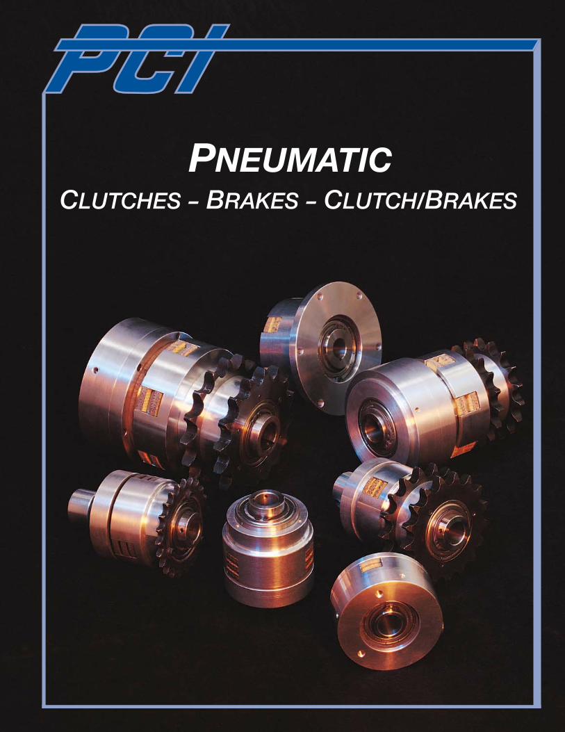
ClutChes - Brakes - ClutCh/Brakes
Pneumatic
PCI Pneumatic Clutches:
Clutches, brakes, clutch/brakes, torque limiters
Torque capacities from 0-6300 in.-lbs
Bolt-on drives, sprockets, v-belt sheaves and gears
Virtually maintenance-free
Custom styles and sizes per specification
NEW!
traction wheel hubassemblies
PCI Traction Wheel Hub Assemblies:
In stock and available for quick shipment
Interchangeable with other manufacturers' hubs
PCI Track Rollers:
Machine ground with ball bearings or tapered roller bearings to accommodate thrust loads
Stud and Yoke Styles Available in:
Regreaseable
Nylon
Stainless steel
High temperature
Custom designs
PCI Cam Followers:
Manufactured with needle bearings for radial load applications
2" through 10" diameter in both Stud and Yoke styles in stock
NEW!
PCI Standard Duty Pulleys& Machined Pulleys:
2" to 12" diameter
Various hub styles
V-groove styles
Trapezoidal crown for maximum concentricity and reduced belt wear
Available with lagging
PCI Stainless Steel Pulleys:
Sanitary/Food Grade
Corrosive/Washdown
Available with lagging
PCI Heavy Duty Pulleys: 14" diameters and larger
72" overall face length
Various hub styles
Flat face or crowned for maximum concentricity and reduced belt wear
Available with lagging
Mine duty and spiral styles available
PCI Wing Pulleys: Self-cleaning
6" diameters and larger
Mine duty and spiral styles available
NEW!
PCI Take-Up Frames:
Available in Wide Slot and Narrow Slot styles
Capable of mounting inside, outside or as part of the conveyor frame
PCI Take-Up Frame Covers:
Keep debris away from your bearings and adjusting screw
Cover rotating shafting and other moving parts as a safety feature
One style fits on existing PCI and Dodge frames
One style fits over existing Take-up Frames
NEW!
PRODUCTS manUfaCTUReD by PC I