Embed Size (px)
Citation preview

PRIMECLUSTER™ Reliant Monitor Services (RMS) with Wizard Tools (Linux®, Solaris™)Configuration and Administration
Edition June 2009

Comments… Suggestions… Corrections…The User Documentation Department would like toknow your opinion of this manual. Your feedback helpsus optimize our documentation to suit your individual needs.
Feel free to send us your comments by e-mail to email: [email protected].
Certified documentation according to DIN EN ISO 9001:2000To ensure a consistently high quality standard anduser-friendliness, this documentation was created tomeet the regulations of a quality management system which complies with the requirements of the standardDIN EN ISO 9001:2000.
cognitas. Gesellschaft für Technik-Dokumentation mbHwww.cognitas.de
Copyright and Trademarks
© c
ogni
tas.
Ges
ells
chft
für
Tech
nik-
Dok
ume
ntat
ion
mb
H 2
002
thr
oug
h 20
09
Pfa
d: D
:\Dat
en\
PC
L\4
.2A
20L
x\u4
2117
.7\e
up\R
MS
wiz
\wiz
-fro
nt.f
m
Copyright © 2002 through 2009 Fujitsu LIMITED.
All rights reserved.Delivery subject to availability; right of technical modifications reserved.
All hardware and software names used are trademarks of their respective manufacturers.

Preface
Introduction
Using the Wizard Tools interface (hvw)
Configuration example
Using the Cluster Admin GUI
Additional administrative tools
Controlling RMS operation
Appendix—Site preparation
Appendix—States
Appendix—Object types
Continued


Appendix—Attributes
Appendix—Environment variables
Appendix—List of manual pages
Glossary
Abbreviations
Figures
Tables
Index


Contents1 Preface . . . . . . . . . . . . . . . . . . . . . . . . . . . . . . 11.1 About this manual . . . . . . . . . . . . . . . . . . . . . . . . . 11.2 PRIMECLUSTER documentation list . . . . . . . . . . . . . . . 21.3 Conventions . . . . . . . . . . . . . . . . . . . . . . . . . . . . 41.3.1 Notation . . . . . . . . . . . . . . . . . . . . . . . . . . . . . . 41.3.1.1 Prompts . . . . . . . . . . . . . . . . . . . . . . . . . . . . . . 41.3.1.2 Manual page section numbers . . . . . . . . . . . . . . . . . . . 41.3.1.3 The keyboard . . . . . . . . . . . . . . . . . . . . . . . . . . . 51.3.1.4 Typefaces . . . . . . . . . . . . . . . . . . . . . . . . . . . . . 51.3.1.5 Example 1 . . . . . . . . . . . . . . . . . . . . . . . . . . . . . 51.3.1.6 Example 2 . . . . . . . . . . . . . . . . . . . . . . . . . . . . . 61.3.2 Command line syntax . . . . . . . . . . . . . . . . . . . . . . . 61.4 Important notes and cautions . . . . . . . . . . . . . . . . . . . 6
Part I: Configuration
2 Introduction . . . . . . . . . . . . . . . . . . . . . . . . . . . . 92.1 PRIMECLUSTER overview . . . . . . . . . . . . . . . . . . . . 92.2 How RMS provides high availability . . . . . . . . . . . . . . . 112.2.1 Applications, resources, and objects . . . . . . . . . . . . . . 112.2.2 Relationship of RMS configurations to the real world . . . . . . 152.2.3 Node and application failover . . . . . . . . . . . . . . . . . . 162.2.4 Controlled applications and controller objects . . . . . . . . . . 172.2.4.1 Follow controllers . . . . . . . . . . . . . . . . . . . . . . . . 192.3 How the Wizard Tools provide easy configuration . . . . . . . . 202.4 RMS wizard products . . . . . . . . . . . . . . . . . . . . . . 212.4.1 RMS Wizard Tools . . . . . . . . . . . . . . . . . . . . . . . . 232.4.2 RMS Wizard Kit . . . . . . . . . . . . . . . . . . . . . . . . . 232.5 Cluster Admin administration tool . . . . . . . . . . . . . . . . 242.6 RMS components . . . . . . . . . . . . . . . . . . . . . . . . 242.6.1 Base monitor . . . . . . . . . . . . . . . . . . . . . . . . . . . 242.6.2 Detectors . . . . . . . . . . . . . . . . . . . . . . . . . . . . 252.6.3 Scripts . . . . . . . . . . . . . . . . . . . . . . . . . . . . . . 252.7 Object types . . . . . . . . . . . . . . . . . . . . . . . . . . . 262.8 Object attributes . . . . . . . . . . . . . . . . . . . . . . . . . 272.9 Environment variables . . . . . . . . . . . . . . . . . . . . . . 272.9.1 Script execution environment variables . . . . . . . . . . . . . 282.10 RMS Directory structure . . . . . . . . . . . . . . . . . . . . . 29
3 Using the Wizard Tools interface (hvw) . . . . . . . . . . . . 313.1 Overview . . . . . . . . . . . . . . . . . . . . . . . . . . . . . 31
U42117-J-Z100-7-76

Contents
3.1.1 RMS Wizard types . . . . . . . . . . . . . . . . . . . . . . . . 323.1.1.1 Turnkey wizards . . . . . . . . . . . . . . . . . . . . . . . . . . 333.1.1.2 Resource wizards . . . . . . . . . . . . . . . . . . . . . . . . . 333.2 General configuration procedure . . . . . . . . . . . . . . . . . 343.3 Creating and editing a configuration . . . . . . . . . . . . . . . 343.3.1 Using the wizard menus . . . . . . . . . . . . . . . . . . . . . 353.3.2 Main configuration menu . . . . . . . . . . . . . . . . . . . . . 363.3.2.1 Main configuration menu when RMS is not active . . . . . . . . 363.3.2.2 Main configuration menu when RMS is running . . . . . . . . . 403.3.3 Secondary menus . . . . . . . . . . . . . . . . . . . . . . . . . 413.3.4 Basic and non-basic settings . . . . . . . . . . . . . . . . . . . 423.4 Activating a configuration . . . . . . . . . . . . . . . . . . . . . 443.5 Configuration elements . . . . . . . . . . . . . . . . . . . . . . 483.5.1 Scripts . . . . . . . . . . . . . . . . . . . . . . . . . . . . . . . 483.5.2 Detectors . . . . . . . . . . . . . . . . . . . . . . . . . . . . . 493.5.3 RMS objects . . . . . . . . . . . . . . . . . . . . . . . . . . . 493.6 Further reading . . . . . . . . . . . . . . . . . . . . . . . . . . 50
4 Configuration example . . . . . . . . . . . . . . . . . . . . . 534.1 Stopping RMS . . . . . . . . . . . . . . . . . . . . . . . . . . 534.2 Creating a configuration . . . . . . . . . . . . . . . . . . . . . 544.3 Adding hosts to the cluster . . . . . . . . . . . . . . . . . . . . 554.4 Creating an application . . . . . . . . . . . . . . . . . . . . . . 574.5 Entering Machines+Basics settings . . . . . . . . . . . . . . . . 604.6 Entering non-basic settings . . . . . . . . . . . . . . . . . . . . 654.7 Specifying a display . . . . . . . . . . . . . . . . . . . . . . . . 674.8 Activating the configuration . . . . . . . . . . . . . . . . . . . . 704.9 Creating a second application . . . . . . . . . . . . . . . . . . 724.10 Setting up a controlling application . . . . . . . . . . . . . . . . 764.11 Specifying controlled applications . . . . . . . . . . . . . . . . 774.12 Activating the configuration a second time . . . . . . . . . . . . 814.13 Starting RMS . . . . . . . . . . . . . . . . . . . . . . . . . . . 82
Part II: Administration
5 Using the Cluster Admin GUI . . . . . . . . . . . . . . . . . . 855.1 Overview . . . . . . . . . . . . . . . . . . . . . . . . . . . . . 855.2 Starting the Cluster Admin GUI . . . . . . . . . . . . . . . . . . 865.2.1 Web-Based Admin View . . . . . . . . . . . . . . . . . . . . . 865.2.2 Login . . . . . . . . . . . . . . . . . . . . . . . . . . . . . . . 875.2.3 Main Cluster Admin window . . . . . . . . . . . . . . . . . . . 905.2.4 Cluster Admin message view . . . . . . . . . . . . . . . . . . . 915.3 Monitoring RMS with Cluster Admin . . . . . . . . . . . . . . . 925.3.1 RMS tree . . . . . . . . . . . . . . . . . . . . . . . . . . . . . 93
U42117-J-Z100-7-76

Contents
5.3.2 Pop-up context menus . . . . . . . . . . . . . . . . . . . . . . 955.3.3 Pop-up confirmation dialogs . . . . . . . . . . . . . . . . . . . 975.3.4 Displaying environment variables . . . . . . . . . . . . . . . . 975.3.5 Displaying object states . . . . . . . . . . . . . . . . . . . . . 995.3.6 Configuration information or object attributes . . . . . . . . . . 101
6 Additional administrative tools . . . . . . . . . . . . . . . . 1036.1 Using the RMS clusterwide table . . . . . . . . . . . . . . . . 1036.1.1 Using context menus from the clusterwide table . . . . . . . . 1066.2 Using RMS graphs . . . . . . . . . . . . . . . . . . . . . . . . 1076.2.1 RMS full graph . . . . . . . . . . . . . . . . . . . . . . . . . . 1076.2.2 Application graph . . . . . . . . . . . . . . . . . . . . . . . . 1126.2.3 Subapplication graph . . . . . . . . . . . . . . . . . . . . . . 1136.2.4 Composite subapplication graph . . . . . . . . . . . . . . . . . 1156.2.5 Using pop-up context menus from the graph . . . . . . . . . . 1176.2.6 Changing the displayed detail level . . . . . . . . . . . . . . . 1186.3 Interpreting display changes . . . . . . . . . . . . . . . . . . . 1226.3.1 Display during RMS configuration changes . . . . . . . . . . . 1226.3.2 Display after RMS shutdown . . . . . . . . . . . . . . . . . . . 1236.4 Viewing RMS log messages . . . . . . . . . . . . . . . . . . . 1266.4.1 Common procedures for switchlog and application log . . . . . 1306.4.2 Time filter . . . . . . . . . . . . . . . . . . . . . . . . . . . . 1316.4.3 Keyword filters . . . . . . . . . . . . . . . . . . . . . . . . . . 1326.4.3.1 Resource Name . . . . . . . . . . . . . . . . . . . . . . . . . 1326.4.3.2 Severity . . . . . . . . . . . . . . . . . . . . . . . . . . . . . 1336.4.3.3 Non-zero exit code . . . . . . . . . . . . . . . . . . . . . . . . 1346.4.3.4 Keyword . . . . . . . . . . . . . . . . . . . . . . . . . . . . . 1346.4.4 Text search . . . . . . . . . . . . . . . . . . . . . . . . . . . . 1356.4.5 Removing filters . . . . . . . . . . . . . . . . . . . . . . . . . 135
7 Controlling RMS operation . . . . . . . . . . . . . . . . . . 1377.1 Managing RMS nodes . . . . . . . . . . . . . . . . . . . . . . 1377.1.1 Starting RMS . . . . . . . . . . . . . . . . . . . . . . . . . . 1377.1.2 Starting RMS automatically at boot time . . . . . . . . . . . . . 1427.1.3 Stopping RMS . . . . . . . . . . . . . . . . . . . . . . . . . . 1437.1.4 Clearing a SysNode Wait state . . . . . . . . . . . . . . . . . 1487.2 Managing RMS applications . . . . . . . . . . . . . . . . . . . 1497.2.1 Overriding automatic application startup . . . . . . . . . . . . 1497.2.2 Switching an application . . . . . . . . . . . . . . . . . . . . . 1517.2.3 Starting an application . . . . . . . . . . . . . . . . . . . . . . 1537.2.4 Stopping an application . . . . . . . . . . . . . . . . . . . . . 1547.2.5 Resetting an application . . . . . . . . . . . . . . . . . . . . . 1557.2.6 Changing AutoSwitchOver setting for an application . . . . . . 1577.2.7 Clearing a fault . . . . . . . . . . . . . . . . . . . . . . . . . . 159
U42117-J-Z100-7-76
Contents
7.2.8 Activating an application . . . . . . . . . . . . . . . . . . . . 1607.3 Using maintenance mode . . . . . . . . . . . . . . . . . . . . 1607.3.1 Entering maintenance mode . . . . . . . . . . . . . . . . . . 1617.3.2 Maintenance mode operating notes . . . . . . . . . . . . . . 1637.3.2.1 Overall cluster restrictions in maintenance mode . . . . . . . . 1637.3.3 Exiting maintenance mode . . . . . . . . . . . . . . . . . . . 1647.3.4 Clearing faults in maintenance mode . . . . . . . . . . . . . . 1657.3.5 Maintenance mode CLI: hvutil -m and -M . . . . . . . . . . . . 167
Part III: Reference
8 Appendix—Site preparation . . . . . . . . . . . . . . . . . 1718.1 Network database files . . . . . . . . . . . . . . . . . . . . . 1718.1.1 /etc/hosts . . . . . . . . . . . . . . . . . . . . . . . . . . . . 1718.1.1.1 Network interface names in /etc/hosts . . . . . . . . . . . . . 1728.1.2 /root/.rhosts (Linux) and /.rhosts (Solaris) . . . . . . . . . . . 1738.2 Configuration resource definitions . . . . . . . . . . . . . . . 1738.2.1 /opt/SMAW/SMAWRrms/etc/hvipalias . . . . . . . . . . . . . 1738.2.1.1 Optional fields . . . . . . . . . . . . . . . . . . . . . . . . . . 1758.2.2 /opt/SMAW/SMAWRrms/etc/hvconsoles . . . . . . . . . . . . 1778.3 Linux file systems . . . . . . . . . . . . . . . . . . . . . . . . 1778.3.1 /etc/fstab.pcl . . . . . . . . . . . . . . . . . . . . . . . . . . . 1788.3.1.1 Configuring file systems for particular applications . . . . . . . 1788.3.1.2 Clusterwide configuration issues . . . . . . . . . . . . . . . . 1798.3.2 /etc/exports.pcl . . . . . . . . . . . . . . . . . . . . . . . . . 1798.4 Solaris file systems . . . . . . . . . . . . . . . . . . . . . . . 1808.4.1 /etc/vfstab.pcl . . . . . . . . . . . . . . . . . . . . . . . . . . 1808.4.1.1 Configuring file systems for particular applications . . . . . . . 1818.4.1.2 Clusterwide configuration issues . . . . . . . . . . . . . . . . 1828.4.1.3 Recommended network settings . . . . . . . . . . . . . . . . 1828.4.2 /etc/dfs/dfstab.pcl . . . . . . . . . . . . . . . . . . . . . . . . 1838.4.2.1 Ensuring NFS daemon startup . . . . . . . . . . . . . . . . . 1848.4.3 NFS Lock Failover . . . . . . . . . . . . . . . . . . . . . . . 1848.4.4 RCFS file systems . . . . . . . . . . . . . . . . . . . . . . . 1858.4.4.1 /etc/dktab . . . . . . . . . . . . . . . . . . . . . . . . . . . . 1858.4.4.2 Server mount control . . . . . . . . . . . . . . . . . . . . . . 1858.4.4.3 Client mount control . . . . . . . . . . . . . . . . . . . . . . . 1868.5 NFS servers . . . . . . . . . . . . . . . . . . . . . . . . . . . 1868.5.1 LVM2 on Linux . . . . . . . . . . . . . . . . . . . . . . . . . 1878.5.2 RC Volume Manager (RCVM) on Solaris . . . . . . . . . . . . 1878.5.3 VxVM . . . . . . . . . . . . . . . . . . . . . . . . . . . . . . 1878.6 Log files . . . . . . . . . . . . . . . . . . . . . . . . . . . . . 1888.6.1 /var/log/messages (Linux) or /var/adm/messages (Solaris) . . 1888.7 Other system services and databases . . . . . . . . . . . . . 188
U42117-J-Z100-7-76

Contents
9 Appendix—States . . . . . . . . . . . . . . . . . . . . . . . 1899.1 Basic states . . . . . . . . . . . . . . . . . . . . . . . . . . . 1899.2 State details . . . . . . . . . . . . . . . . . . . . . . . . . . . 191
10 Appendix—Object types . . . . . . . . . . . . . . . . . . . . 193
11 Appendix—Attributes . . . . . . . . . . . . . . . . . . . . . 19511.1 Attributes available to the user . . . . . . . . . . . . . . . . . . 19511.2 Attributes managed by configuration wizards . . . . . . . . . . 203
12 Appendix—Environment variables . . . . . . . . . . . . . . 20712.1 Setting environment variables . . . . . . . . . . . . . . . . . . 20712.2 Global environment variables . . . . . . . . . . . . . . . . . . 20812.3 Local environment variables . . . . . . . . . . . . . . . . . . . 21312.4 Script execution environment variables . . . . . . . . . . . . . 217
13 Appendix—RMS command line interface . . . . . . . . . . . 21913.1 Available RMS CLI commands . . . . . . . . . . . . . . . . . 219
14 Appendix—List of manual pages . . . . . . . . . . . . . . . 22314.1 CCBR . . . . . . . . . . . . . . . . . . . . . . . . . . . . . . 22314.2 CF . . . . . . . . . . . . . . . . . . . . . . . . . . . . . . . . 22314.3 CFS . . . . . . . . . . . . . . . . . . . . . . . . . . . . . . . 22414.4 CIP . . . . . . . . . . . . . . . . . . . . . . . . . . . . . . . . 22414.5 PAS . . . . . . . . . . . . . . . . . . . . . . . . . . . . . . . 22514.6 RCVM . . . . . . . . . . . . . . . . . . . . . . . . . . . . . . 22514.7 Resource Database . . . . . . . . . . . . . . . . . . . . . . . 22514.8 RMS . . . . . . . . . . . . . . . . . . . . . . . . . . . . . . . 22614.9 RMS Wizards . . . . . . . . . . . . . . . . . . . . . . . . . . 22814.10 SCON . . . . . . . . . . . . . . . . . . . . . . . . . . . . . . 22814.11 SF . . . . . . . . . . . . . . . . . . . . . . . . . . . . . . . . 22814.12 SIS . . . . . . . . . . . . . . . . . . . . . . . . . . . . . . . . 22914.13 Web-Based Admin View . . . . . . . . . . . . . . . . . . . . . 23014.14 Miscellaneous utilities . . . . . . . . . . . . . . . . . . . . . . 230
Glossary . . . . . . . . . . . . . . . . . . . . . . . . . . . . . . . . . . 231
Abbreviations . . . . . . . . . . . . . . . . . . . . . . . . . . . . . . . 249
Figures . . . . . . . . . . . . . . . . . . . . . . . . . . . . . . . . . . . 253
Tables . . . . . . . . . . . . . . . . . . . . . . . . . . . . . . . . . . . 261
Index . . . . . . . . . . . . . . . . . . . . . . . . . . . . . . . . . . . . 263
U42117-J-Z100-7-76

Contents
U42117-J-Z100-7-76

1 PrefacePRIMECLUSTER™ Reliant® Monitor Services (RMS) is a software monitor designed to guarantee the high availability of applications in a cluster of nodes. This manual describes how to configure RMS using the RMS Wizards and how to administer RMS using the Cluster Admin GUI.
The manual is aimed at system administrators who create and maintain RMS configurations. Familiarity with the following system functions and components is assumed:
● PRIMECLUSTER family of products
● Linux® or Solaris™ operating system
● Non-PRIMECLUSTER products such as volume managers and storage area networks.
This document assumes that the PRIMECLUSTER software has been installed as described in the PRIMECLUSTER Installation Guide for your operating system.
1.1 About this manual
“Part I: Configuration” provides an introduction to RMS and describes how to create and maintain RMS configurations:
● The chapter “Introduction” on page 9 provides an introduction to RMS termi-nology and describes basic principles of operation.
● The chapter “Using the Wizard Tools interface (hvw)” on page 29 describes how to configure RMS using the RMS Wizard Tools.
● The chapter “Configuration example” on page 51 illustrates the Wizard Tools configuration process for two simple applications on a small cluster.
“Part II: Administration” describes how to manage RMS operation:
● The chapter “Using the Cluster Admin GUI” on page 87 describes how to start and use the Cluster Admin graphical user interface (GUI), which is the primary tool for all RMS administrative functions.
● The chapter “Additional administrative tools” on page 105 describes the RMS clusterwide table, RMS graphs, and the RMS log viewer.
U42117-J-Z100-7-76 1

PRIMECLUSTER documentation list Preface
● The chapter “Controlling RMS operation” on page 139 describes common RMS administrative functions available through the Cluster Admin GUI, including the equivalent CLI procedures.
“Part III: Reference” provides background information about RMS operation and settings:
● The chapter “Appendix—Site preparation” on page 173 describes network and file settings required for RMS operation.
● The chapter “Appendix—States” on page 185 lists the object states that are supported by RMS.
● The chapter “Appendix—Object types” on page 189 lists the object types that are supplied with RMS.
● The chapter “Appendix—Attributes” on page 191 lists the attributes that are supported by RMS object types.
● The chapter “Appendix—Environment variables” on page 203 describes the RMS environment variables.
● The chapter “Appendix—RMS command line interface” on page 215 lists the RMS administrative CLI commands.
● The chapter “Appendix—List of manual pages” on page 219 lists the manual pages for PRIMECLUSTER CLI commands related to RMS.
1.2 PRIMECLUSTER documentation list
The documents listed below provide details about PRIMECLUSTER products. Please contact your sales representative for ordering information.Books can be ordered via the Internet shop http://manualshop.ts.fujitsu.com. ● Release notices for all products—These documentation files are included
as HTML files on the PRIMECLUSTER CD. Release notices provide late-breaking information about installation, configuration, and operation. Read this information first.
● Concepts Guide (Solaris, Linux)—Provides conceptual details on the PRIME-CLUSTER family of products.
● Installation Guide (Solaris)—Provides instructions for installing and upgrading PRIMECLUSTER products.
● Installation Guide (Linux)—Provides instructions for installing and upgrading PRIMECLUSTER products.
2 U42117-J-Z100-7-76

Preface PRIMECLUSTER documentation list
● Web-Based Admin View (Solaris, Linux) Operation Guide—Provides information on using the Web-Based Admin View management GUI.
● Cluster Foundation (CF) (Solaris) Configuration and Administration Guide—Provides instructions for configuring and administering the PRIME-CLUSTER Cluster Foundation.
● Cluster Foundation (CF) Configuration and Administration Guide (Linux) — Provides instructions for configuring and administering the PRIME-CLUSTER Cluster Foundation.
● Reliant Monitor Services (RMS) with Wizard Tools (Linux, Solaris) Configuration and Administration Guide—Provides instructions for configuring and adminis-tering PRIMECLUSTER Reliant Monitor Services using the Wizard Tools interface.
● Reliant Monitor Services (RMS) with PCS (Linux, Solaris) Configuration and Administration Guide—Provides instructions for configuring and adminis-tering PRIMECLUSTER Reliant Monitor Services using the PCS (PRIME-CLUSTER Configuration Services) interface.
● Reliant Monitor Services (RMS) (Linux, Solaris) Reference Guide—Describes operational principles and diagnostic procedures for the RMS high avail-ability manager, including how to view and interpret RMS log files. Provides a list of all RMS error messages with a probable cause and suggested action for each condition.
● Scalable Internet Services (SIS) (Linux, Solaris) Configuration and Administration Guide—Provides information on configuring and administering Scalable Internet Services (SIS).
● Global Disk Services (Solaris, Linux) Configuration and Administration Guide—Provides information on configuring and administering Global Disk Services (GDS).
● Global File Services (Solaris, Linux) Configuration and Administration Guide—Provides information on configuring and administering Global File Services (GFS).
● Global Link Services (Solaris, Linux) Configuration and Administration Guide: Redundant Line Control Function—Provides information on configuring and administering the redundant line control function for Global Link Services (GLS).
● Global Link Services (Solaris, Linux) Configuration and Administration Guide: Multipath Function—Provides information on configuring and administering the multipath function for Global Link Services (GLS).
U42117-J-Z100-7-76 3

Conventions Preface
● Data Management Tools (Solaris) Configuration and Administration Guide—Provides reference information on the Volume Manager (RCVM) and File Share (RCFS) products. (Not available in all markets)
● SNMP Reference Manual (Solaris, Linux)—Provides reference information on the Simple Network Management Protocol (SNMP) product.
● RMS Wizards documentation package—Available on the PRIMECLUSTER CD. These documents deal with Wizard Tools topics such as the configuration of file systems and IP addresses. They also describe the various types of available RMS wizards.
1.3 Conventions
To standardize the presentation of material, this manual uses a number of notational, typographical, and syntactical conventions.
1.3.1 Notation
This manual uses the following notational conventions.
1.3.1.1 Prompts
Command line examples that require system administrator (or root) rights to execute are preceded by the system administrator prompt, the hash sign (#). Entries that do not require system administrator rights are preceded by a dollar sign ($).
In some examples, the notation <nodename># indicates a root prompt on the specified node. For example, a command preceded by shasta1# would mean that the command was run as user root on the node named shasta1.
1.3.1.2 Manual page section numbers
References to operating system commands may sometimes be followed by their manual page section numbers in parentheses, e.g., cp(1).
4 U42117-J-Z100-7-76

Preface Conventions
1.3.1.3 The keyboard
Keystrokes that represent nonprintable characters are displayed as key icons such as [Enter] or [F1]. For example, [Enter] means press the key labeled Enter; [Ctrl-b] means hold down the key labeled Ctrl or Control and then press the [B] key.
1.3.1.4 Typefaces
The following typefaces highlight specific elements in this manual.
Typeface conventions are shown in the following examples.
1.3.1.5 Example 1
Several entries from an /etc/passwd file are shown below:
root:x:0:1:0000-Admin(0000):/:/sbin/kshsysadm:x:0:0:System Admin.:/usr/admin:/usr/sbin/sysadmsetup:x:0:0:System Setup:/usr/admin:/usr/sbin/setupdaemon:x:1:1:0000-Admin(0000):/:
Typeface Usage
Constant Width
Computer output and program listings; commands, file names, manual page names and other literal programming elements in the main body of text.
Italic Variables in a command line that you must replace with an actual value. May be enclosed in angle brackets to emphasize the difference from adjacent text, e.g., <nodename>RMS. Unless directed otherwise, you should not enter the angle brackets.
The name of an item in a character-based or graphical user interface. This may refer to a menu item, a radio button, a checkbox, a text input box, a panel, or a window title.
Bold Items in a command line that you must type exactly as shown.
U42117-J-Z100-7-76 5

Important notes and cautions Preface
1.3.1.6 Example 2
To use the cat(1) command to display the contents of a file, enter the following command line:
$ cat file
1.3.2 Command line syntax
The command line syntax observes the following conventions.
1.4 Important notes and cautions
Material of particular interest is preceded by one of the following symbols:
I Contains important information about the subject at hand.
V Caution
Indicates a situation that can cause harm to data.
Symbol Name Meaning
[ ] Brackets Enclose an optional item.
{ } Braces Enclose two or more items of which only one is used. The items are separated from each other by a vertical bar (|).
| Vertical bar When enclosed in braces, it separates items of which only one is used. When not enclosed in braces, it is a literal element indicating that the output of one program is piped to the input of another.
( ) Parentheses Enclose items that must be grouped together when repeated.
... Ellipsis Signifies an item that may be repeated. If a group of items can be repeated, the group is enclosed in parentheses.
6 U42117-J-Z100-7-76

U42117-J-Z100-7-76
Part I: Configuration


2 IntroductionThis chapter contains general information on Reliant Monitor Services (RMS), introduces the PRIMECLUSTER family of products, details how RMS, RMS Wizard Tools, and the RMS Wizard Kit work together to produce high-availability configurations, and introduces Cluster Admin.
Chapter contents:
● “PRIMECLUSTER overview” on page 9
● “How RMS provides high availability” on page 11
● “How the Wizard Tools provide easy configuration” on page 20
● “RMS wizard products” on page 21
● “Cluster Admin administration tool” on page 24
● “RMS components” on page 24
● “Object types” on page 26
● “Object attributes” on page 27
● “Environment variables” on page 27
● “RMS Directory structure” on page 29
2.1 PRIMECLUSTER overview
The PRIMECLUSTER family of products is an integrated set of cluster services, including configuration and administration services, high availability, scalability, parallel application support, cluster file system, and cluster volume management. Figure 1 illustrates the relationship of PRIMECLUSTER services to each other and to the operating system environment.
U42117-J-Z100-7-76 9

PRIMECLUSTER overview Introduction
Figure 1: Overview of PRIMECLUSTER products
This manual focuses on PRIMECLUSTER products and services that relate to high availability operation (shown with a solid gray background in the figure above). They are as follows:
● RMS—This high availability manager is a software monitor that provides high availability (HA) for customer applications in a cluster of nodes. Its task is to monitor systems and application resources, to identify any failures, and to provide application availability virtually without interruption in the event of any such failures.
RMS also provides integrated services for market-specific applications. See your sales representative for availability and details.
● RMS Wizard Tools—This configuration tool provides a character-based interface to create RMS configurations. It includes templates for generic applications and commonly used resources.
The RMS Wizard Kit works with the Wizard Tools to configure popular enter-prise products for operation with RMS.
● Cluster Admin—The Cluster Admin GUI is the primary administrative tool for RMS.
● Cluster Foundation (CF)—This comprehensive suite provides cluster admin-istration and communication services for user applications and other PRIMECLUSTER services.
PRIMECLUSTER products shown with a dotted background in the figure above are described in their respective manuals. See the section “PRIMECLUSTER documentation list” in the Preface.
Parallelapplications
(PAS)
ScalableInternet Services
(SIS)
Customservices
(GDS, GFS, GLS)
Cluster management and configuration(Cluster Admin)
RMS configuration(Wizard Tools)
Cluster services(CF)
Highavailability
(RMS)
Operating system kernel
User interface
10 U42117-J-Z100-7-76

Introduction How RMS provides high availability
2.2 How RMS provides high availability
RMS provides high availability of a customer’s application by controlling and monitoring the state of all resources in use by a given application. Resources include items such as network interfaces, local and remote file systems, and storage area networks. RMS also monitors the state of each host in the cluster.
2.2.1 Applications, resources, and objects
RMS relies on a virtual representation of the cluster called a configuration. The configuration represents each machine, application, and system resource as an object, and the objects are logically arranged in a tree structure according to their dependencies. For instance, suppose a user application depends on a network interface and a file system in order to operate properly. In the tree structure, the corresponding application object would appear as a parent and the network and file system objects would appear as its children. The tree structure is commonly known as a graph.
Each object in the graph contains the state of the corresponding item along with any other parameters that may be required. An object is typically in the online (enabled, available) state or the offline (disabled, unavailable) state, but other states are possible according to the type of object. For the complete list of states supported by RMS, see “Appendix—States” on page 189.
At runtime, the configuration is managed by the RMS base monitor, which initiates actions when an object’s state changes, or, in the case of a timeout, when an object has remained in the same state for some specified time interval even though a change was expected. This design is known as a state machine.
Nodes and heartbeats
Machines that are members of a cluster are called nodes. When RMS monitors the health of a node, its highest priority is to detect a complete failure of the node or its base monitor. Its second priority is to detect slow response times that may be caused by system overloads. RMS uses two mechanisms to detect these problems.
RMS transmits a UDP heartbeat signal at regular intervals. If the elapsed time since the last heartbeat from a node exceeds an adjustable connection timeout, RMS assumes the node has lost connectivity. RMS then begins a recovery period for the node. If the node heartbeat is detected during the recovery period, RMS assumes the node is functional and returns it to normal status. However,
U42117-J-Z100-7-76 11

How RMS provides high availability Introduction
if RMS receives no heartbeats from the node before the recovery period expires, it assumes the node is down, even if other communication with the node is possible.
Once RMS marks a node as down, it takes a series of steps to ensure appli-cation and cluster integrity. First, it is necessary to ensure that the node is truly shut down. Otherwise, the node and its applications could unexpectedly recover later, causing conflicts and data corruption. To avoid these problems, RMS directs the Shutdown Facility (described later) to eliminate the node. This is often done by rebooting the node or turning off its power, but the exact action depends on which shutdown agents have been configured for the node. Only after the node has been eliminated is it safe for RMS to restart the node’s appli-cations elsewhere in the cluster. The process of automatically switching appli-cations from a failed node to a healthy node is called application failover.
Application switchover impacts cluster performance, so it is important to choose a recovery timeout that avoids false detection of node outages. The optimum UDP recovery time depends on the conditions in the cluster. A short recovery period is the best choice to deal with failures of nodes or base monitors. However, a long recovery period allows time for overloaded nodes to respond, which avoids unnecessary shutdowns. If the UDP method is used by itself, these opposing requirements make it difficult to tune the recovery time in large or busy clusters.
In addition, the UDP method can be unreliable, because it has three potential points of failure: first, an outgoing request for a response may not get through to the remote node, so it has no reason to respond; second, the remote node may be so busy that it cannot respond within the recovery period, especially if the recovery timeout is set to a low value; third, a response packet may be sent from the remote node, but it may not get through to the local node. In all three cases, the local node cannot take action until the recovery period expires.
To improve cluster response, RMS uses its Enhanced Lock Manager (ELM) as the primary method to determine machine states and connectivity. ELM is not a polling method. Instead, it relies on locks that are managed at the kernel level by the Cluster Foundation. When a node joins the cluster, it creates a lock and holds it as long as its base monitor is running. The lock is released when the node or its base monitor goes down. The state of the locks is available locally on each node, because the Cluster Foundation maintains them in the background.
ELM is designed to address the high priority issue of node or base monitor failures. The UDP heartbeat can therefore be optimized to detect slow node response, with the recovery time set to a relatively large value. This provides an
12 U42117-J-Z100-7-76
Introduction How RMS provides high availability
important complement to ELM. A node with an overloaded CPU or network interface may respond so slowly that the underlying Cluster Foundation cannot determine the state of the node’s lock. If this condition persists, the UDP heartbeat recovery period eventually expires, and RMS proceeds to shut down the node. ELM’s efficiency and reliability make this a very infrequent occur-rence.
Experts can manually disable ELM for rolling upgrade or debugging operations. In this case, when RMS starts up, the expert must also manually adjust the heartbeat recovery timeout to a smaller value.
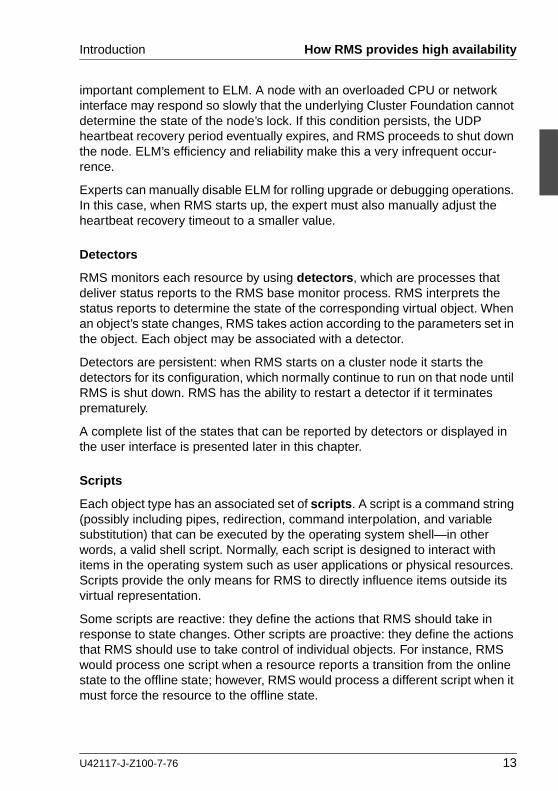
Detectors
RMS monitors each resource by using detectors, which are processes that deliver status reports to the RMS base monitor process. RMS interprets the status reports to determine the state of the corresponding virtual object. When an object’s state changes, RMS takes action according to the parameters set in the object. Each object may be associated with a detector.
Detectors are persistent: when RMS starts on a cluster node it starts the detectors for its configuration, which normally continue to run on that node until RMS is shut down. RMS has the ability to restart a detector if it terminates prematurely.
A complete list of the states that can be reported by detectors or displayed in the user interface is presented later in this chapter.
Scripts
Each object type has an associated set of scripts. A script is a command string (possibly including pipes, redirection, command interpolation, and variable substitution) that can be executed by the operating system shell—in other words, a valid shell script. Normally, each script is designed to interact with items in the operating system such as user applications or physical resources. Scripts provide the only means for RMS to directly influence items outside its virtual representation.
Some scripts are reactive: they define the actions that RMS should take in response to state changes. Other scripts are proactive: they define the actions that RMS should use to take control of individual objects. For instance, RMS would process one script when a resource reports a transition from the online state to the offline state; however, RMS would process a different script when it must force the resource to the offline state.
U42117-J-Z100-7-76 13

How RMS provides high availability Introduction
Scripts are transient: after performing their programmed tasks, they exit and return a status code to the base monitor.
A complete list of the scripts that may be specified for RMS objects is presented later in this chapter.
Object types
Most high-availability applications rely on a set of physical resources such as network interfaces, files systems, or virtual disks. RMS represents these as gResource objects. Most gResource objects have scripts that allow them to be brought online or taken offline.
Internally, RMS represents an actual application that runs in the operating system environment as a userApplication object. The set of gResource objects that represent the actual application’s resource requirements are called its dependent resources. Bringing a userApplication object to the online state, along with all of its dependent resources, is called online processing. Taking a userApplication object to the offline state, along with all of its dependent resources, is called offline processing.
Each node that may run one or more applications in the high availability config-uration is represented by an RMS SysNode object. Like gResource objects and userApplication objects, SysNode objects can be brought online or taken offline, and they have an associated set of scripts. However, booting up or shutting down the corresponding physical machine requires more than simple script processing.
For the complete list of the RMS object types supported by the Wizard Tools, see “Appendix—Object types” on page 193.
Shutdown Facility
While scripts and detectors provide a direct interface between RMS and the operating system, the Shutdown Facility (SF) provides an indirect interface to the machines in the cluster. When it necessary to take a SysNode object offline, RMS works with the SF to guarantee that the corresponding node has been physically shut down, or killed. RMS waits for successful completion of the node kill before switching any userApplication from the offline SysNode to another SysNode. This prevents any user application from running on two machines at the same time, which could lead to data corruption.
For more information about the Shutdown Facility, see the PRIMECLUSTER Cluster Foundation (CF) Configuration and Administration Guide for your operating system.
14 U42117-J-Z100-7-76

Introduction How RMS provides high availability
2.2.2 Relationship of RMS configurations to the real world
It is important to understand that RMS does not interact directly with “real-world” items such as machines, users’ applications, or system resources—it interacts only with the objects in its virtual representation. Figure 2 illustrates the relationship between an actual user application in the operating system environment and the corresponding userApplication object in an RMS configuration.
Figure 2: Interface between RMS and the operating system
Note that the interface between the RMS virtual representation and the actual operating system depends entirely on the scripts and detectors provided by the configuration tools. The script in the figure represents any of the standard scripts discussed later in this chapter: it reports whether or not it completed its tasks successfully by returning a status code, and RMS combines this with the status code from the object’s detector to determine the object’s state. RMS has no other way to determine what actually happened to the user application in the operating system environment (the part of the figure below the dashed line).
userApplicationobject
script
RMS base monitor
User application
detectorprocess
RM
Sco
nfig
urat
ion
Ope
ratin
gsy
stem
scriptexecutioncontrol
scriptstatuscodes
detectorstatuscodes
applicationstatus
applicationcontrol
U42117-J-Z100-7-76 15

How RMS provides high availability Introduction
For instance, if a userApplication object’s Online script reports success, its detector reports that it is online, and all of its resources are online, then RMS considers that object to be online, regardless of the state of the actual user application. Similarly, if a resource object’s detector reports an Offline state, it does not necessarily mean that the physical resource is unavailable.
I For reliable high availability operation, RMS requires scripts that properly control the corresponding real world items, and detectors that accurately reflect the items’ states.
Configuration terminology
This manual discusses configuration procedures within the RMS context (repre-sented by the part of Figure 2 above the dashed line). Strictly speaking, our principle concern is with SysNode objects, userApplication objects, and other RMS entities, and not the real-world items they represent.
However, it is intuitive to use terms such as “node” instead of “SysNode object” and “application” instead of “userApplication object,” because the relation-ships are so close, and because it is always understood we are working from the RMS perspective. This also helps to simplify many of the technical discus-sions. Therefore, unless there is a need to distinguish between an RMS object and the actual item it represents, this manual and the configuration tools it describes use the following terms interchangeably:
● “node” and “SysNode object” and “SysNode”
● “application” and “userApplication object” and “userApplication”
● “resource” and “gResource object” and “gResource”
The descriptions of object states and attributes are abbreviated similarly. For instance, instead of “the gResource object named xyz is in the Offline state,” it is customary to say, “the xyz file system is offline.” It is also common to refer to a script by its attribute name, so “the script specified by the PreOnlineScript attribute” becomes simply “the PreOnlineScript.”
2.2.3 Node and application failover
During normal operation, one instance of RMS runs on each node in the cluster. Every instance communicates with the others to coordinate the actions configured for each userApplication. If a node crashes or loses contact with
16 U42117-J-Z100-7-76
Introduction How RMS provides high availability
the rest of the cluster, then RMS can switch all userApplication objects from the failed node to a surviving node in the cluster. This operation is known as failover.
Failover can also operate with individual applications. Normally, a userApplication object is allowed to be online on only one node at a time. (Exceptions to this rule are shared objects like Oracle RAC vdisk.) If a fault occurs within a resource used by a userApplication object, then only that userApplication can be switched to another node in the cluster. userApplication failover involves offline processing for the object on the first node, followed by online processing for the object on a second node.
There are also situations in which RMS requires a node to be shut down, or killed. In any case, before switching applications to a new node, RMS works together with the PRIMECLUSTER Shutdown Facility to guarantee that the original node is completely shut down. This helps to protect data integrity.
RMS also has the ability to recover a resource locally; that is, a faulted resource can be brought back to the online state without switching the entire userApplication to another cluster node.
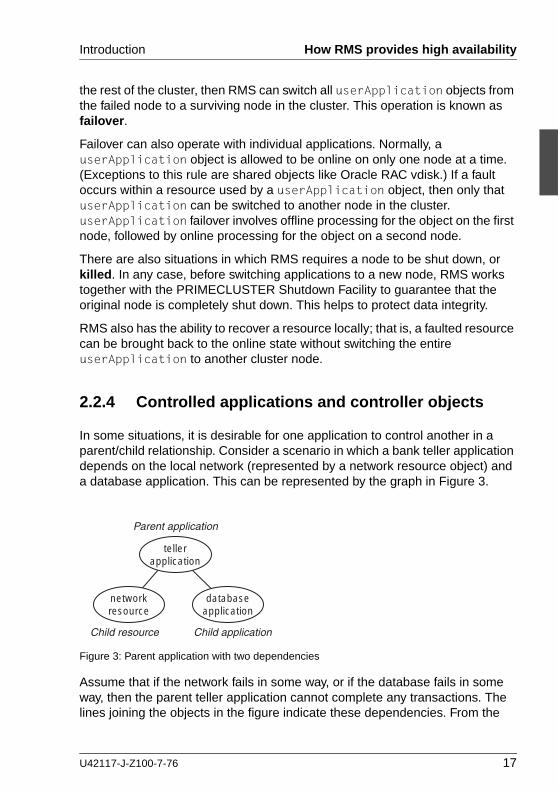
2.2.4 Controlled applications and controller objects
In some situations, it is desirable for one application to control another in a parent/child relationship. Consider a scenario in which a bank teller application depends on the local network (represented by a network resource object) and a database application. This can be represented by the graph in Figure 3.
Figure 3: Parent application with two dependencies
Assume that if the network fails in some way, or if the database fails in some way, then the parent teller application cannot complete any transactions. The lines joining the objects in the figure indicate these dependencies. From the
Parent application
Child applicationChild resource
tellerapplication
databaseapplication
networkresource
U42117-J-Z100-7-76 17

How RMS provides high availability Introduction
RMS perspective, then, we would like both the network resource and the database application to be configured in similar ways: they should both act as dependent resources that must be online if the teller application is to function properly.
However, RMS does not allow any application to be directly configured as the child of another application. Instead, RMS accommodates parent/child relation-ships between applications by providing an intermediate controller object, which is often simply called a controller. Unlike other resource objects, a controller has no scripts or detectors. Instead, it propagates online and offline requests from the parent to the child application, and it determines its status from that of the child application.
Figure 4 demonstrates how RMS would represent the banking scenario with the teller application, the controller, and the database application all running on node1. For the purposes of this example and the discussions that follow, only the applications and the controller are included in the illustration; the resource object representing the network interface is not shown.
Figure 4: RMS representation of controlled application
I Each controlled application requires a separate controller as a child of the parent application. Also, controllers exist only for internal RMS management purposes—there is no equivalent in the context of the real-world operating system.
If a child changes to an offline or faulted state, RMS will attempt to recover locally or switch the parent, the child, and the dependent resources to another node.
userApplication object (controlling application)
userApplication object (controlled application)
controller object
SysNode object (cluster node)
tellerapplication
databaseapplication
controller
node1
18 U42117-J-Z100-7-76
Introduction How RMS provides high availability
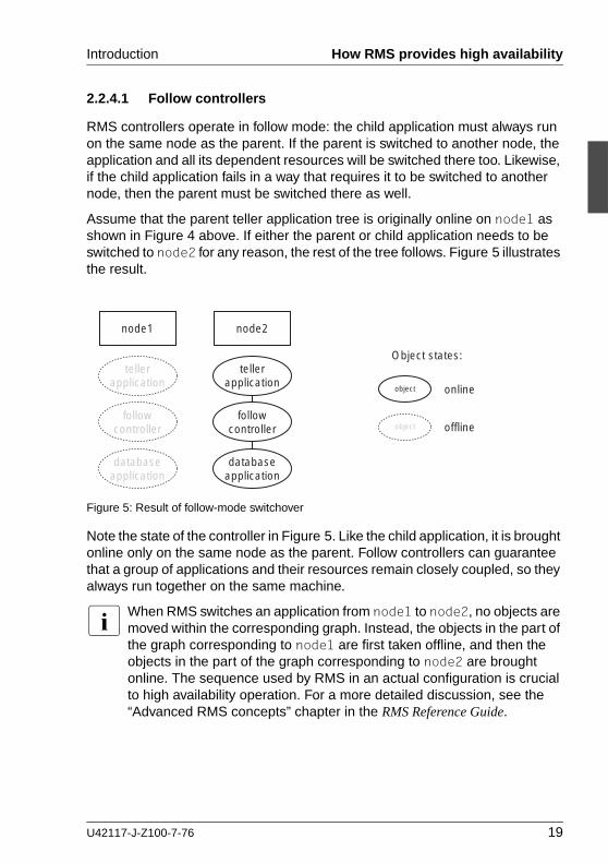
2.2.4.1 Follow controllers
RMS controllers operate in follow mode: the child application must always run on the same node as the parent. If the parent is switched to another node, the application and all its dependent resources will be switched there too. Likewise, if the child application fails in a way that requires it to be switched to another node, then the parent must be switched there as well.
Assume that the parent teller application tree is originally online on node1 as shown in Figure 4 above. If either the parent or child application needs to be switched to node2 for any reason, the rest of the tree follows. Figure 5 illustrates the result.
Figure 5: Result of follow-mode switchover
Note the state of the controller in Figure 5. Like the child application, it is brought online only on the same node as the parent. Follow controllers can guarantee that a group of applications and their resources remain closely coupled, so they always run together on the same machine.
I When RMS switches an application from node1 to node2, no objects are moved within the corresponding graph. Instead, the objects in the part of the graph corresponding to node1 are first taken offline, and then the objects in the part of the graph corresponding to node2 are brought online. The sequence used by RMS in an actual configuration is crucial to high availability operation. For a more detailed discussion, see the “Advanced RMS concepts” chapter in the RMS Reference Guide.
tellerapplication
databaseapplication
followcontroller
tellerapplication
databaseapplication
followcontroller
object
object
online
offline
Object states:
node1 node2
U42117-J-Z100-7-76 19

How the Wizard Tools provide easy configuration Introduction
2.3 How the Wizard Tools provide easy configuration
RMS is a mature product with many features and options. Experts who develop, debug, and fine tune complete RMS configurations must know how RMS works and what RMS needs in order to function properly. For each application in the configuration, the expert must do the following:
● Define the set of resources used by the application, including:
– Disks
– Volume managers
– File systems
– processes to be monitored
– IP addresses
● Define the relationship between each resource and its dependent resources, e.g., which file system depends on which virtual or physical disk, which processes depend on which file systems, and so forth.
● Define the relationship between the applications being controlled; for example, which applications must be up and running before others are allowed to start.
● Provide scripts to bring each resource online and offline.
● Provide a detector to determine the state of each resource.
Configuring the above set of requirements by hand can be quite time consuming and prone to errors. This is why the RMS Wizard Tools were developed.
The PRIMECLUSTER RMS Wizard Tools allow the creation of flexible and quality-tested RMS configurations while minimizing your involvement. A simple user interface prompts you for details regarding your applications and resources. Using these details, the Wizard Tools automatically select the proper scripts and detectors and combine them in a pre-defined structure to produce a complete RMS configuration.
Specialists skilled in popular applications and in RMS worked together to create the RMS wizards. The wizards are designed to easily configure RMS for certain popular applications such as Oracle or SAP R/3, and they are flexible enough to create custom RMS configurations that can control any other type of appli-cation.
20 U42117-J-Z100-7-76

Introduction RMS wizard products
2.4 RMS wizard products
The RMS wizards are divided into the following separate products:
● RMS Wizard Tools—user interface, general-purpose application wizards, and basic set of subapplication wizards. Provided as a standard component of RMS
● RMS Wizard Kit—set of custom wizards designed to configure specific appli-cations. Available as additional product.
Figure 6 depicts the relationship between RMS, the Wizard Tools, and the RMS Wizard Kit.
U42117-J-Z100-7-76 21

RMS wizard products Introduction
Figure 6: Relationship between RMS and RMS Wizards
ApplicationSpecificDetectorApplication
SpecificDetectorApplication
specificdetector
ApplicationSpecificDetectorApplication
SpecificDetectorApplication
specificscript
ApplicationSpecificDetectorApplication
SpecificDetectorApplication
specificwizard
RMS Wizard Kit
Wizarddatabase
hvw
ResourceSpecificDetector
ResourceSpecificDetector
Resourcespecificscript
ResourceSpecificDetector
ResourceSpecificDetector
Resourcespecificdetector
RMS Wizard Tools
RMS
RMSconfig
fileRMS CLI
RMSbase monitor
Node statedetector
Cluster Admin Other cluster services
22 U42117-J-Z100-7-76

Introduction RMS wizard products
2.4.1 RMS Wizard Tools
The RMS Wizard Tools provides the following for basic resource types (such as file systems and IP addresses):
● Online scripts
● Offline scripts
● Detectors
In addition to the basic resource support, the RMS Wizard Tools package contains the hvw command, which is the entry point to the user configuration interface. The hvw interface provides a simple menu-driven interface to allow a user to enter information specific to applications placed under the control of RMS. hvw also provides an interface through which application-specific knowledge can be dynamically added to provide turnkey solutions for those applications typically found in the data center. These application-specific modules are provided by the RMS Wizard Kit.
2.4.2 RMS Wizard Kit
The RMS Wizard Kit provides application knowledge modules which can be used by the hvw command. The knowledge modules provide hvw with infor-mation specific to popular applications, which greatly eases the configuration task. The following are also provided for specific applications:
● Online scripts
● Offline scripts
● Detectors
I For information on the availability of the RMS Wizard Kit, contact your local customer support service or refer to the RMS Wizards documen-tation package.
U42117-J-Z100-7-76 23

Cluster Admin administration tool Introduction
2.5 Cluster Admin administration tool
The Cluster Admin GUI is the primary administrative tool for RMS. It allows users full access to the application control functions of RMS, including the following:
● RMS startup and shutdown
● Application startup and shutdown
● Manual application reset and switchover
● Visual cues for resource and application fault isolation
● Fault clearing capability
● Graphs of application and resources
● Logs for nodes and applications
● Maintenance mode control
2.6 RMS components
The RMS product is made up of the following software components that run on each node in the cluster:
● Base monitor
● Detectors
● Scripts
2.6.1 Base monitor
The base monitor process is the decision-making segment of the RMS process group. It has the following functions:
● Stores the current configuration of resources as represented by objects, their attributes, and their interdependent relationships
● Receives user requests for specific actions from the Cluster Admin graphical user interface (GUI) or the RMS command line interface (CLI)
● Monitors the heartbeat from every node to keep track of each machine’s status and its connectivity to the rest of the cluster
24 U42117-J-Z100-7-76

Introduction RMS components
● Receives input from detectors and monitors state changes
● Launches scripts to bring applications and their dependent resources online or offline
● Dictates the sequencing of the resource state changes to ensure resources and applications are brought online or offline in the correct order
● Initiates and controls automatic application switchover in case of a resource or node failure, or when directed by a user request
● Performs various administrative functions
2.6.2 Detectors
Detectors are independent processes that monitor specific sets of resources in order to determine their state. The detector does not determine whether the current state of a resource is the correct state or not—that is the role of the base monitor.
Detectors for common system functions are provided by the Wizard Tools. Additional application-specific detectors are included with the Wizard Kit.
Some objects provided by RMS, such as the controller object, have no detector. Instead, RMS calculates the state of the object based on factors such as transitory processes and the states of its dependent resources.
2.6.3 Scripts
RMS uses scripts to perform actions such as moving a resource from one state to another (for example, from Offline to Online). The two types of scripts are as follows:
● Request-triggered scripts initiate a state change to a resource.
The request-triggered scripts are as follows:
– InitScript —Runs only once when RMS is first started
– PreCheckScript—Determines if Online or Standby processing is needed or possible
– PreOfflineScript—Prepares a transition to an Offline state
– OfflineScript—Transitions a resource to an Offline state
U42117-J-Z100-7-76 25

Object types Introduction
– PreOnlineScript—Prepares a transition to an Online state
– OnlineScript—Transitions a resource to an Online state
● State-triggered scripts react to specific events.
The state-triggered scripts are as follows:
– PostOnlineScript—Reaction to the transition to the Online state
– PostOfflineScript—Reaction to the transition to the Offline state
– OfflineDoneScript—Reaction to a userApplication reaching the Offline state
– FaultScript—Reaction to a resource transitioning to the Faulted state
– WarningScript—Reaction to a detector reporting the Warning state (available only for selected resources)
Scripts for common system functions are included with the subapplications provided by the Wizard Tools.
2.7 Object types
An object type represents a group of similar resources that are monitored by the same detector (for example, all disk drives). Using the Wizard Tools, you can create configuration files that contain objects of various types, each repre-senting resources or groups of resources to be monitored by RMS. The supported types are as follows:
● SysNode
● userApplication
● gResource
● controller
● andOp
● orOp
Refer to the chapter “Appendix—Object types” on page 193 for the supported types, their required attributes, and a brief description of each object.
26 U42117-J-Z100-7-76

Introduction Object attributes
I This information is provided for reference only. These objects are created by the Wizard Tools during the generation phase of the configuration process. The type of an object may be listed in diagnostic messages for use by RMS experts.
2.8 Object attributes
An attribute is the part of an object definition that specifies how the base monitor acts and reacts for a particular resource during normal operation. An attribute can include a device name and configuration scripts. Users can specify attributes in any order in the object definition.
Refer to the chapter “Appendix—Attributes” on page 195 for the supported types, their associated values, and a description of each attribute.
I This information is provided for reference only. The values are deter-mined by the Wizard Tools during the generation phase of the configu-ration process.
2.9 Environment variables
RMS uses global and local environment variables:
● Global variables generally control clusterwide operations and must have the same setting on all nodes in the cluster. At runtime, RMS maintains global environment variables in the ENV object.
I Global variable settings (ENV) are included in the configurations checksum that is common to the cluster. The checksum is verified on each node during startup of the base monitor. RMS will fail to start if it detects a checksum difference between the values on any two nodes.
● Local variables can differ from node to node. RMS maintains local environment variables in the ENVL object.
I Local variable settings (ENVL) are not included in the configurations checksum that is common to the cluster.
RMS creates the ENV and ENVL objects dynamically when the base monitor starts up:
U42117-J-Z100-7-76 27

Environment variables Introduction
1. First, it loads global and local variables from the <RELIANT_PATH>/bin/hvenv file, which is installed with the package.
V Caution
Do not modify the <RELIANT_PATH>/bin/hvenv file.
2. Next, it loads both global and local variables from the <RELIANT_PATH>/bin/hvenv.local file, which contains configuration-specific variables that are typically set by the Wizard Tools. These settings override the installation defaults. Experts may change the contents of this file manually with a standard text editor. In any case, changes to the hvenv.local file will not take effect until the next RMS startup.
I The RELIANT_PATH global variable is defined at installation. By default, it is set to /opt/SMAW/SMAWRrms.
I A /tmp directory that is nearly full may result in RMS errors, because the base monitor uses the sort(1) command to sort RMS environment variables.
While RMS is running, you can display the environment variables with the hvdisp command, which does not require root privilege:
● Use ‘hvdisp ENV’ to display the global list.
● Use ‘hvdisp ENVL’ to display the local list.
Refer to the chapter “Appendix—Environment variables” on page 207 for a description of all global and local environment variables. The appendix also describes how to change the value of any environment variable.
2.9.1 Script execution environment variables
When the RMS invokes a script on behalf of an object, it provides a set of variables in the script’s environment that can be used for decision processing at runtime. Since these variables exist only within the context of the script while it is carrying out its tasks, they are not usually visible in the RMS user or admin-istrator environment. In rare cases, they could appear in a diagnostic message in the system log or on the console.
The section “Script execution environment variables” on page 217 provides a complete description of each of these variables.
28 U42117-J-Z100-7-76

Introduction RMS Directory structure
2.10 RMS Directory structure
RMS software consists of a number of executables, scripts, files, and commands, all located relative to the directory specified in the RELIANT_PATH environment variable. Table 1 illustrates the directory structure of the RMS software after it has been correctly installed.
As summarized in Table 2, RMS log files are located in the directory specified in the RELIANT_LOG_PATH environment variable.
Name Contents
RELIANT_PATH Base directory. Default: /opt/SMAW/SMAWRrms
<RELIANT_PATH>/bin Executables, including detectors, commands, and scripts.
<RELIANT_PATH>/build Work and storage area for configuration files.
<RELIANT_PATH>/etc Miscellaneous files used by RMS and the configuration tools.
<RELIANT_PATH>/include RMS include files (header files) used by detectors and configuration files.
<RELIANT_PATH>/lib RMS runtime libraries.
<RELIANT_PATH>/us RMS source files. The names of the files in this directory are reserved and should not be used to name any configuration files that the user may create.
RELIANT_STARTUP_PATH Search directory for configuration files. Default: <RELIANT_PATH>/build
Table 1: RMS base directory structure
U42117-J-Z100-7-76 29

RMS Directory structure Introduction
Name Contents
RELIANT_LOG_PATH Contains files that can be used for RMS analyzing and debugging, including the RMS switchlog. The base monitor and detectors create log files here. Default: /var/opt/SMAWRrms/log
The same directory has subdirectories that contain backup copies of the RMS log files. Each backup subdirectory has a name of the form yyyy-mm-dd_HH:MM:SS to indicate the date and time when the backup was created.
Table 2: Log directory structure
30 U42117-J-Z100-7-76
3 Using the Wizard Tools interface (hvw)
This chapter describes how to configure high availability for customer applica-tions using the RMS Wizards.
Chapter contents:
● The section “Overview” on page 31 gives a brief overall description of the configuration process and the RMS Wizards.
● The section “General configuration procedure” on page 34 outlines the four major steps involved in every configuration procedure.
● The section “Creating and editing a configuration” on page 34 describes the wizard interface and how it is used to specify a configuration.
● The section “Activating a configuration” on page 44 describes how to activate a configuration after it has been created or modified.
● The section “Configuration elements” on page 48 provides additional details about basic RMS elements specified in every configuration.
● The section “Further reading” on page 50 contains a list of related documents that provide additional information about the wizards.
All the following procedures assume the Cluster Foundation (CF) software has been properly installed, configured, and started. See the Cluster Foundation (CF) Configuration and Administration Guide for details.
3.1 Overview
The chapter “Introduction” on page 9 describes the components necessary for configuring applications for high availability. It is extremely important that you define applications and the resources that are used by them. Resources are entities like disks, file systems, processes, IP addresses, and so forth.
This definition also needs to include the following information:
● How the applications and their resources are related to each other
● What scripts bring resources online and offline
● Which detectors monitor the state of which resources
U42117-J-Z100-7-76 31

Overview Using the Wizard Tools interface (hvw)
For example, if a node should fail to be available, the node that is to take its place must have been defined beforehand so that the applications depending on this node are able to continue operating with minimal interruption. Once the necessary information is defined, you can then set up an RMS configuration. A configuration of this magnitude, however, requires a great deal of expert knowledge.
The RMS Wizards are tools that allow you to set up an RMS configuration in a way that is simple, flexible, and quality-tested. Furthermore, these tools conform to a well-documented, standard design.To configure RMS with the wizards, you supply information about the applications using a menu-driven interface. The wizards use this information to set up a complete RMS configuration.
The following sections describe these wizards and the way they are used to configure high availability from a general point of view.
3.1.1 RMS Wizard types
The RMS Wizards are divided into two categories:
● RMS Wizard Tools—This is a general-purpose package that includes the following components:
– The hvw menu-based configuration interface
– The GENERIC application wizard, which allows you to configure a wide range of applications
– The DEMO wizard, which provides a simple demonstration of the Wizard Tools and RMS
– The basic set of resource-oriented wizards, which provide scripts and detectors for basic resources such as file systems, volume managers, and IP addresses. They are used by the GENERIC and DEMO wizards as well as components in the Wizard Kit.
● RMS Wizard Kit—These application-oriented wizards are designed to cover complete applications and perform their tasks on the basis of the turnkey concept. The R/3 and ORACLE wizards are components of the Wizard Kit.
I For information on the availability of the RMS Wizard Kit, contact your local customer support service or refer to the RMS Wizards documen-tation package. See the section “Further reading” on page 50 for more information.
32 U42117-J-Z100-7-76

Using the Wizard Tools interface (hvw) Overview
3.1.1.1 Turnkey wizards
Turnkey wizards provide predefined structures of resources to monitor almost every basic operating system object. This relieves the user of the tedious task of linking system resources according to their dependencies.
Many turnkey wizards are designed to configure a specific type of application. The configuration described in the chapter “Configuration example” on page 53 uses the GENERIC and DEMO turnkey wizards. Other examples are the R/3 wizard and the ORACLE wizard. By convention, turnkey wizards have names with all uppercase letters.
3.1.1.2 Resource wizards
Resource wizards (sometimes called sub-application wizards) configure lower-level resources such as file systems or IP addresses. They are invoked by turnkey wizards and are not designed to interact directly with the user. Resource wizards have names that begin with one uppercase letter followed by one or more lowercase letters.The following are some of the more important resource wizards:
● Cmdline—Configures any generic resource type by specifying StartScript (to bring the resource online), StopScript (to send the resource offline) and CheckScript (to check the state of a resource).
● Controller—Configures applications that control other applications.
● Fsystem—Configures local or remote file systems.
● Gds—Configures disk classes administrated by Global Disk Services (GDS).
● Gls—Configures the IP addresses administrated by Global Link Services (GLS).
● Ipaddress—Configures the IP addresses that are needed for communication over a LAN interface.
● Rcvm—Configures disk groups administrated by the PRIMECLUSTER Volume Manager (not available in all areas).
● Vxvm—Configures disk groups administrated by the Veritas volume manager (not available in all areas).
U42117-J-Z100-7-76 33

General configuration procedure Using the Wizard Tools interface (hvw)
3.2 General configuration procedure
RMS configuration always involves these four steps:
Ê Stop RMS.
Refer to the section “Stopping RMS” on page 143. You can use the Cluster Admin GUI or the command line interface from any node in the cluster.
Ê Create or edit the configuration.
The next section provides general information, and the chapter “Configu-ration example” on page 53 walks through an example.
Ê Activate the configuration.
Activation includes generation and distribution. See the section “Activating a configuration” on page 44.
Ê Start RMS.
Refer to the section “Starting RMS” on page 137. You can use the Cluster Admin GUI or the command line interface from any node in the cluster.
I To avoid network access problems, perform RMS configuration tasks as root, and ensure that CF is installed, properly configured, and running as described in the PRIMECLUSTER Installation Guide for your operating system.
3.3 Creating and editing a configuration
You can bring up an existing Wizard Tools configuration that is currently activated on the host systems of a cluster. In this case, you might call up the configuration because it is to be modified using the wizards while RMS is stopped. On the other hand, you might want to use the wizards to set up a new configuration. The commands for starting the wizards are as follows:
● hvw
Runs RMS Wizard Tools using the last activated configuration stored in the <RELIANT_PATH>/etc/CONFIG.rms startup file. If this file does not exist or activation is being done for the first time, RMS creates the default configu-ration, config.
34 U42117-J-Z100-7-76

Using the Wizard Tools interface (hvw) Creating and editing a configuration
● hvw -n configname
Edits an existing configuration or creates a new configuration using the specified name. The configuration will be stored in the <RELIANT_PATH>/build/configname.us startup file.
The sample configuration used for demonstration purposes in this chapter shows how to set up a new configuration called mydemo using the DEMO turnkey wizard. This example would be called up as follows:
hvw -n mydemo
The hvw command is documented in the online manual pages. Refer to the chapter “Appendix—List of manual pages” on page 223 for additional infor-mation.
3.3.1 Using the wizard menus
The hvw command produces character-driven menus that guide you in a way designed to be self-explanatory. The following are some of the most frequently used menu operations and items:
● Selecting items—This is normally done by typing the number of the item followed by the [Enter] or [Return] key. Within the menu, a prompting line indicates the kind of input that is required. A >> prompt indicates that a string of text should be entered.
● Responding to messages—Within the menus, several kinds of messages are displayed. One type of message might be to inform the user about the activities that the wizard has performed; for example, a consistency check that ended in a positive result. Other messages may prompt the user to continue the configuration procedure with a certain activity; for example, choosing an application name.
● HELP—This item provides user assistance and is available at the top of every wizard menu.
● QUIT—This quits the wizard menu system.
● RETURN—This moves one level upward in the menu system; that is, from a subordinate menu to the menu it was called from.
● SAVE+EXIT and NOSAVE+EXIT—These save or discard your input and then exit. SAVE+EXIT will be disabled in read-only mode, and it may be disabled if the configuration is inconsistent at that point.
U42117-J-Z100-7-76 35

Creating and editing a configuration Using the Wizard Tools interface (hvw)
3.3.2 Main configuration menu
The Main configuration menu appears immediately after a configuration has been called up. This top-level menu shows the state of the RMS cluster by indicating either one the following:
● RMS is inactive
● The list of nodes where RMS is up and running
The Main configuration menu changes dynamically at run time depending on whether RMS is running in the cluster and whether the configuration being edited is the current configuration.
If RMS is running anywhere in the cluster, actions that could modify a running configuration are not available. Additionally, the menu items that are available are modified such that no changes can be made to the running configuration.
When RMS is running but the configuration being edited is not the same as the currently active one, the main menu is not restricted except that the Configuration-Activate menu option is not available.
3.3.2.1 Main configuration menu when RMS is not active
If RMS is not running anywhere, then the entire top level menu is presented without restrictions. Figure 7 shows the Main configuration menu window when RMS is inactive.
Figure 7: Main configuration menu when RMS is not active
shasta1: Main configuration menu, current configuration: mydemo
No RMS active in the cluster
Choose an action:
1) HELP
2) QUIT
3) Application-Create
4) Application-Edit
5) Application-Remove
6) Application-Clone
7) Configuration-Generate
8) Configuration-Activate
9) Configuration-Copy
10) Configuration-Remove
11) Configuration-Freeze
12) Configuration-Thaw
13) Configuration-Edit-Global-Settings
14) Configuration-Consistency-Report
15) Configuration-ScriptExecution
16) RMS-CreateMachine
17) RMS-RemoveMachine
36 U42117-J-Z100-7-76

Using the Wizard Tools interface (hvw) Creating and editing a configuration
Menu items
The Main configuration menu can perform the following activities when RMS is not running anywhere in the cluster:
● Application-Create—Specifies which application to configure for high avail-ability. In addition, this operation specifies all the relevant settings for the application so that it can run in a high-availability configuration monitored by RMS. Among the most important of these settings is the name of the appli-cation and the list of nodes on which the application may run.
The user application should be configured to run on multiple nodes for a high-availability configuration.
The wizard assists you by supplying menus with basic and non-basic attributes, assigns values to the attributes, and prompts you if an attribute is mandatory.
By choosing the appropriate turnkey wizard for an application, the wizard will then provide predefined elements, like scripts and detectors, for the appli-cation in question. These elements have been developed especially for the respective type of application.
The wizard will also carry out consistency checks at certain stages of the configuration procedure in order to prevent inconsistent applications from running in a high-availability configuration.
● Application-Edit—Modifies an existing application.
An existing application can be modified using this menu item. The following modes are available for editing an application:
– Turnkey mode (highly recommended)—Turnkey mode is the default mode. This mode is highly recommended because it simplifies compli-cated tasks like creating linkages between application and sub-applica-tions.
– Non-turnkey mode (only for expert users)—Non-turnkey mode is meant for advanced/expert users only. If this mode is to be used, some rules must be followed. Otherwise, the resulting configuration may remain in an inconsistent state and RMS will not start. Usage of this mode is not within the scope of this guide.
● Application-Remove—Removes an existing application from the high-avail-ability configuration.
U42117-J-Z100-7-76 37

Creating and editing a configuration Using the Wizard Tools interface (hvw)
● Application-Clone—Clones an application. This feature is provided for users who want to create a new application that differs only slightly from an existing one. To do this, clone an application and modify only the parts that are necessary to create a new one.
● Configuration-Generate—Performs the following:
– Runs consistency checks on the configuration
– Creates the RMS graph of the configuration and stores it in the configname.us file. The graph is a hierarchical description of objects that represent the nodes, applications, and resources used in the configu-ration.
During the Configuration-Generate phase, the wizard indicates the progress with a series of dots on the screen. Each dot represents an application or resource that has been successfully generated.
Normally, you would use Configuration-Activate (described below) to generate and distribute the configuration in one step. Configuration-Generate provides a way to generate and check a configuration without distributing it to the other nodes in the cluster. This may be useful for testing or debugging (see also the description for Configuration-ScriptExecution later in this list).
I Configuration-Generate is always available, whether RMS is running or not.
● Configuration-Activate—Generates and distributes a configuration.
Selecting this item performs both the generation and distribution phases in one step. The generation phase is described above.
The distribution phase prepares the cluster for RMS, ensuring that all the required data is put into place. The wizard copies the configuration data to every reachable node specified in the configuration and installs all necessary files. If one or more nodes is not available during the distribution phase, you can later use Configuration-Push (described in the next section) to update only those nodes.
I Configuration-Activate is not available if RMS is already running on one or more nodes.
● Configuration-Copy—Produces a copy of an existing configuration. This is often used to make a backup before an existing, tested configuration is enhanced.
● Configuration-Remove—Removes (deletes) any existing configuration.
38 U42117-J-Z100-7-76

Using the Wizard Tools interface (hvw) Creating and editing a configuration
● Configuration-Freeze—Prevents further changes to a configuration. This marks the configuration as read-only so it can be viewed, but not modified.
I Configuration-Freeze is password protected: you will be prompted to create a password before the configuration is locked.
● Configuration-Thaw—Releases the configuration from the frozen (read-only) state so it can be modified.
I Configuration-Thaw is password protected: you must enter the correct password before the configuration is unlocked.
● Configuration-Edit-Global-Settings—Modifies settings that affect the entire configuration. This includes settings for the detectors and the operation mode of the hvw command. This item is also used to specify the alternate interconnects (AlternateIps) for the cluster.
● Configuration-Consistency-Report—Provides a consistency check that verifies whether an application is running within a high-availability configuration and has actually been created using the configuration data provided by the respective wizard.
The wizard compares the currently activated wizard checksum against the wizard database checksum. One checksum is called the Live-Info, the other is called the BuildInfo. If both checksums match for an application, it is certified that its running version conforms to what was configured by the wizard.
● Configuration-ScriptExecution—Allows administrators to run any script independent of RMS.
By selecting the resources configured for the application, the user can execute the scripts that are to bring the resources online or offline. To see the online scripts being executed, you can go through the resource list, which is displayed for this purpose, in ascending order. The return code indicates the proper functioning of the respective script.
● RMS-CreateMachine—Defines the list of machines which constitute the cluster. During the activation phase, the RMS configuration will be distributed to all the nodes in this list.
Applications managed by RMS must each be configured to run on one or more machines in this pool. Therefore, complete this step before creating any application.
● RMS-RemoveMachine—Removes machines from the list of cluster nodes.
U42117-J-Z100-7-76 39

Creating and editing a configuration Using the Wizard Tools interface (hvw)
3.3.2.2 Main configuration menu when RMS is running
Wizard Tools menus change dynamically according to whether or not RMS is running in the following locations:
● anywhere in the cluster
● on the local node
If RMS is running on any of the cluster machines, any operation which could potentially modify the currently active configuration is not allowed.
In particular, when RMS is running on the local node, the Main configuration menu changes as shown in Figure 8.
Figure 8: Main configuration menu when RMS is running
When RMS is running, the following entries either appear or change their behavior:
● Application-View—Views an existing application in read-only mode.
● Configuration-Generate—Same functionality as when RMS is not running.
● Configuration-Copy—Produces a copy of an existing configuration. This is often used to make a backup before an existing, tested configuration is enhanced.
I Configuration-Copy cannot overwrite the configuration that is currently running.
shasta1: Main configuration menu, current configuration: mydemo
RMS up on: shasta1RMS -- RMS down on: shasta2RMS
1) HELP
2) QUIT
3) Application-View
4) Configuration-Generate
5) Configuration-Copy
6) Configuration-Remove
7) Configuration-Freeze
8) Configuration-Edit-Global-Settings
9) Configuration-Consistency-Report
10) Configuration-ScriptExecution
11) Configuration-Push
12) RMS-ViewMachine
Choose an action:
40 U42117-J-Z100-7-76

Using the Wizard Tools interface (hvw) Creating and editing a configuration
● Configuration-Remove—Removes (deletes) any existing configuration except the one that is currently running.
● Configuration-Push—Distributes a complete copy of the currently running configuration to a specific cluster node.
When a configuration is activated, some nodes may not be available. This menu item allows you to update individual cluster nodes that are brought up later, when RMS is already running. For example, if you changed the config-uration while a node was down for maintenance, you could use Configuration-Push to update the node after it was restarted.
I Configuration-Push is available only after the configuration has been activated.
● RMS-ViewMachine—Displays the list of nodes on which RMS is currently running.
3.3.3 Secondary menus
Each of the main menu items has a number of secondary menus. The secondary menus themselves can have sub-menus.
The Creation: Application type selection menu (Figure 9) is an example of a secondary menu. You see this menu after selecting Application-Create from the main menu.
Figure 9: Application type selection
Creation: Application type selection menu:
1) HELP
2) QUIT
3) RETURN
4) OPTIONS
5) DEMO
6) GENERIC
7) LIVECACHE
8) R3ANY
9) R3CI
10) RTP
Application Type: 5
U42117-J-Z100-7-76 41
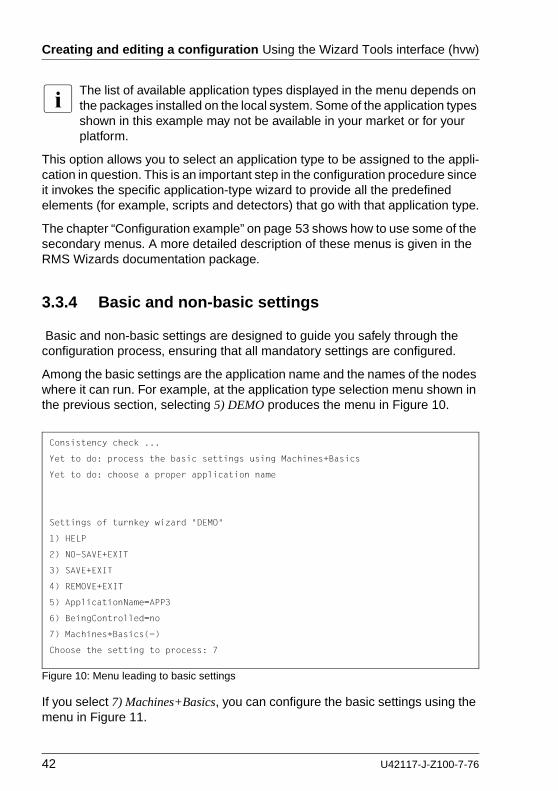
Creating and editing a configuration Using the Wizard Tools interface (hvw)
I The list of available application types displayed in the menu depends on the packages installed on the local system. Some of the application types shown in this example may not be available in your market or for your platform.
This option allows you to select an application type to be assigned to the appli-cation in question. This is an important step in the configuration procedure since it invokes the specific application-type wizard to provide all the predefined elements (for example, scripts and detectors) that go with that application type.
The chapter “Configuration example” on page 53 shows how to use some of the secondary menus. A more detailed description of these menus is given in the RMS Wizards documentation package.
3.3.4 Basic and non-basic settings
Basic and non-basic settings are designed to guide you safely through the configuration process, ensuring that all mandatory settings are configured.
Among the basic settings are the application name and the names of the nodes where it can run. For example, at the application type selection menu shown in the previous section, selecting 5) DEMO produces the menu in Figure 10.
Figure 10: Menu leading to basic settings
If you select 7) Machines+Basics, you can configure the basic settings using the menu in Figure 11.
Consistency check ...
Yet to do: process the basic settings using Machines+Basics
Yet to do: choose a proper application name
Settings of turnkey wizard "DEMO"
1) HELP
2) NO-SAVE+EXIT
3) SAVE+EXIT
4) REMOVE+EXIT
5) ApplicationName=APP3
6) BeingControlled=no
7) Machines+Basics(-)
Choose the setting to process: 7
42 U42117-J-Z100-7-76

Using the Wizard Tools interface (hvw) Creating and editing a configuration
Figure 11: Menu to configure basic settings
The menu displays the application’s current attribute settings, some of which may be set automatically by the wizards. Attributes enclosed in parentheses are optional.
After you complete the configuration of the basic settings, the non-basic settings menu appears (Figure 12). Non-basic settings include specifications for resources such as file systems, IP adresses, disks, and so forth.
Consistency check ...
Machines+Basics (app1:consistent)
Choose the setting to process:
1) HELP
2) -
3) SAVE+EXIT
4) REMOVE+EXIT
5) AdditionalMachine
6) AdditionalConsole
7) Machines[0]=shasta1RMS
8) (PreCheckScript=)
9) (PreOnlineScript=)
10) (PostOnlineScript=)
11) (PreOfflineScript=)
12) (OfflineDoneScript=)
13) (FaultScript=)
14) (AutoStartUp=no)
15) (AutoSwitchOver=No)
16) (PreserveState=no)
17) (PersistentFault=0)
18) (ShutdownPriority=)
19) (OnlinePriority=)
20) (StandbyTransitions=)
21) (LicenseToKill=no)
22) (AutoBreak=yes)
23) (HaltFlag=no)
24) (PartialCluster=0)
25) (ScriptTimeout=)
U42117-J-Z100-7-76 43

Activating a configuration Using the Wizard Tools interface (hvw)
Figure 12: Menu to configure non-basic settings
I The list of available subapplications displayed in the menu depends on the packages installed on the local system. Some of the subapplications shown in this example may not be available in your market or for your platform.
3.4 Activating a configuration
As described in section “General configuration procedure” on page 34, activating a configuration is the third of the four fundamental steps required to set up a high-availability configuration. The activation phase comprises a number of tasks, among which are generation and distribution of a configu-ration.
I You must stop RMS on all nodes in the cluster before you activate a configuration.
The starting point for the activation phase is the Main configuration menu (see Figure 13).
Consistency check ...
Yet to do: process at least one of the non-basic settings
Settings of turnkey wizard "DEMO"
Choose the setting to process:
1) HELP
2) -
3) SAVE+EXIT
4) -
5) ApplicationName=APP1
6) Machines+Basics(app1)
7) CommandLines(-)
8) Controllers(-)
9) DEMO(-)
10) LocalFileSystems(-)
11) RemoteFileSystems(-)
12) IpAddresses(-)
13) RawDisks(-)
14) RC-VolumeManagement(-)
15) VERITAS-VolumeManagement(-)
16) EMC-RdfManagement(-)
17) FibreCat-MirrorView(-)
18) Gds:Global-Disk-Services(-)
19) Gls:Global-Link-Services(-)
44 U42117-J-Z100-7-76

Using the Wizard Tools interface (hvw) Activating a configuration
Figure 13: Main configuration menu
Ê Select the Configuration-Activate item by entering the number 8.
The activation is performed by the wizard. No further input is required at this stage.
During the activation phase, the wizard executes a series of tasks and displays the status on the screen. The completion of a task is indicated by the word done or a similar expression (see Figure 14).
shasta1: Main configuration menu, current configuration: mydemo
No RMS active in the cluster
Choose an action: 8
1) HELP
2) QUIT
3) Application-Create
4) Application-Edit
5) Application-Remove
6) Application-Clone
7) Configuration-Generate
8) Configuration-Activate
9) Configuration-Copy
10) Configuration-Remove
11) Configuration-Freeze
12) Configuration-Thaw
13) Configuration-Edit-Global-Settings
14) Configuration-Consistency-Report
15) Configuration-ScriptExecution
16) RMS-CreateMachine
17) RMS-RemoveMachine
U42117-J-Z100-7-76 45

Activating a configuration Using the Wizard Tools interface (hvw)
Figure 14: Activating a configuration
Among the tasks carried out by Configuration-Activate are generation and distri-bution of the configuration. The wizard performs a consistency check of the graph created in the generation of the configuration before distributing the configuration to all nodes specified in the configuration.
The test to see whether RMS is up on one of the nodes in the cluster is required since activation cannot be performed if RMS is running. In this case, RMS would need to be shut down first.
I The Configuration-Activate process removes persistent status information on all affected nodes.
After the configuration has been activated successfully, you can return to the Main configuration menu. From there, you can quit the configuration procedure.
About to activate the configuration mydemo ...
Testing for RMS to be up somewhere in the cluster ... done.
Arranging sub applications topologically ... done.
Check for all applications being consistent ... done.
Running overall consistency check ... done.
Generating pseudo code [one dot per (sub) application]: ... done.
Generating RMS resources........................... done
hvbuild using /usr/opt/reliant/build/wizard.d/mydemo/mydemo.us
About to distribute the new configuration data to hosts: shasta1RMS,shasta2RMS
The new configuration was distributed successfully.
About to put the new configuration in effect ... done.
The activation has finished successfully.
Hit CR to continue
46 U42117-J-Z100-7-76

Using the Wizard Tools interface (hvw) Activating a configuration
Ê Press [Enter] to return to the Main configuration menu (see Figure 15).
Figure 15: Quitting the Main configuration menu
Ê Select QUIT by entering the number 2.
This ends the activation phase of the configuration process. Usually, the next step is to start RMS to monitor the newly-configured application.
Ê Start RMS with the GUI or with the following command:
hvcm -a
shasta1: Main configuration menu, current configuration: mydemo
No RMS active in the cluster
Choose an action: 2
1) HELP
2) QUIT
3) Application-Create
4) Application-Edit
5) Application-Remove
6) Application-Clone
7) Configuration-Generate
8) Configuration-Activate
9) Configuration-Copy
10) Configuration-Remove
11) Configuration-Freeze
12) Configuration-Thaw
13) Configuration-Edit-Global-Settings
14) Configuration-Consistency-Report
15) Configuration-ScriptExecution
16) RMS-CreateMachine
17) RMS-RemoveMachine
U42117-J-Z100-7-76 47

Configuration elements Using the Wizard Tools interface (hvw)
3.5 Configuration elements
This section discusses some basic elements that are part of a high-availability configuration. Most of them have been mentioned in previous sections. Additional details are provided here to assist you in understanding how they are used by the wizards.
I Users do not have to deal with any of the items listed in this section directly. RMS Wizards manage all the basic elements for a high avail-ability configuration. This section is provided only to help users better understand the configuration elements.
3.5.1 Scripts
Scripts are used in a high-availability configuration to perform several kinds of actions. Among the most important types of actions are the following:
● Bringing a resource to an Online state
● Bringing a resource to an Offline state
As an example of a script sending a resource Offline, you might think of a file system that has to be unmounted on a node where a fault occurs. An offline script would use the umount command to unmount the file system. Another script might use the mount command to mount it on a different node.
Besides such online and offline scripts, there are also pre-online and pre-offline scripts for preparing transition into the respective states, as well as a number of other scripts.
The RMS Wizards provide a complete set of scripts for several pre-defined application types such as R/3 or Oracle. If you assign your application to one of these standard types, you automatically take advantage of the built-in scripts.
I The hvexec command executes scripts for a high-availability configu-ration monitored by RMS. For more details on the command hvexec please refer to the primer.htm document, which is described in the section “Further reading” on page 50.
48 U42117-J-Z100-7-76

Using the Wizard Tools interface (hvw) Configuration elements
3.5.2 Detectors
Detectors are processes that have the task of monitoring resources. If there is a change in the state of a resource (for example, of a disk group) the detector in charge notifies the RMS base monitor. The base monitor may then decide to have a script executed as a reaction to this changed state.
Like the built-in scripts described in the previous section, the RMS Wizards provide built-in detectors for pre-defined application types. If you assign your application to one of these standard types, it automatically uses the built-in detectors.
3.5.3 RMS objects
A high-availability configuration can be seen as a set or group of objects with interdependencies. Any application or resource that is part of the configuration is then represented by one of the objects. The interdependences of objects can be displayed as a graph called the RMS graph.
These are the most important object types used in RMS configurations:
● userApplication—Represents an application to be configured for high-availability.
● SysNode—Represents a machine that is running as a node in a cluster.
● gResource—Represents a generic resource that is to be defined according to the needs of a customer application.
● Controller—Provides a dependency linkage so that a child application can act as a resource of the parent application.
In a typical configuration, one detector can be associated with all objects of the same type.
U42117-J-Z100-7-76 49

Further reading Using the Wizard Tools interface (hvw)
3.6 Further reading
The preceding sections were intended to make the reader familiar with some basic concepts and methods of the RMS Wizards. More information may be obtained from a number of documents that provide further reading on these tools and the way they are used.
RMS Wizards documentation package
The RMS Wizards documentation package is available in HTML format on the PRIMECLUSTER CD-ROM. After installation, the documents can also be found in the following locations:
/opt/SMAW/SMAWRrms/htdocs.solaris/wizards.en/ (Solaris)
/usr/doc/packages/SMAWRhv-do/wizards.en/ (Linux)
The information is presented in the following files and subdirectories:
● feature_description.htm
Describes the features added to recent versions of the RMS Wizard Tools.
● primer.htm
Provides an introduction to the RMS Wizards, covering many features in more detail than is possible in this chapter.
● wizards/
Provides information on individual wizards of all three kinds described in this chapter. Covers turnkey wizards, resource wizards, and other wizards, including the generic wizard.
● scripts_and_tools/
Provides information on some scripts and tools that may be useful in setting up a high-availability configuration by means of the RMS Wizards. Includes gresources.htm, which contains descriptions of a number of detectors.
● manuals/
Provides current manual pages for commands that are frequently used to configure an application with the RMS Wizards. The hvw and the hvexec commands, which were also described in this chapter, are explained here in more detail.
50 U42117-J-Z100-7-76

Using the Wizard Tools interface (hvw) Further reading
Manual pages
Information on the commands that are used for configuration with the RMS Wizards may also be obtained by calling up the online manual pages with the man command.
Manual pages are available, for instance, for the hvw, hvcm, and hvexec commands, which were used in the procedures described in this chapter.
U42117-J-Z100-7-76 51

Further reading Using the Wizard Tools interface (hvw)
52 U42117-J-Z100-7-76

4 Configuration exampleThis chapter provides an example of the configuration process using the RMS Wizards. Two simple applications are configured for operation on a small cluster. The example includes the following steps:
● “Stopping RMS” on page 53
● “Creating a configuration” on page 54
● “Adding hosts to the cluster” on page 55
● “Creating an application” on page 57
● “Entering Machines+Basics settings” on page 60
● “Entering non-basic settings” on page 65
● “Specifying a display” on page 67
● “Activating the configuration” on page 70
● “Creating a second application” on page 72
● “Setting up a controlling application” on page 76
● “Specifying controlled applications” on page 77
● “Activating the configuration a second time” on page 81
● “Starting RMS” on page 82
An abbreviated version of this example appears in the PRIMECLUSTER Instal-lation Guide for your operating system.
I To avoid network access problems, perform RMS configuration tasks as root, and ensure that CF is installed, properly configured, and running as described in the PRIMECLUSTER Installation Guide for your operating system.
4.1 Stopping RMS
Before you create or edit a configuration, ensure that RMS is not active on any machine that would be affected by the changes. You can use the Cluster Admin GUI (see the section “Stopping RMS” on page 143) or you can enter the following command to stop RMS on all nodes from any machine in the cluster:
# hvshut -a
U42117-J-Z100-7-76 53

Creating a configuration Configuration example
4.2 Creating a configuration
Ê Enter the following command to generate the wizard menu for the configu-ration example, mydemo:
# hvw -n mydemo
This will create an RMS configuration file named mydemo.us in the /opt/SMAW/SMAWRrms/build/ directory. If you choose a different name and location, the combined length of the file name and path should not exceed 80 characters.
The RMS configuration menu appears, displaying the name of the configuration at the top of the menu (Figure 16).
Figure 16: Main configuration menu
shasta1: Main configuration menu, current configuration: mydemo
No RMS active in the cluster
Choose an action:
1) HELP
2) QUIT
3) Application-Create
4) Application-Edit
5) Application-Remove
6) Application-Clone
7) Configuration-Generate
8) Configuration-Activate
9) Configuration-Copy
10) Configuration-Remove
11) Configuration-Freeze
12) Configuration-Thaw
13) Configuration-Edit-Global-Settings
14) Configuration-Consistency-Report
15) Configuration-ScriptExecution
16) RMS-CreateMachine
17) RMS-RemoveMachine
54 U42117-J-Z100-7-76

Configuration example Adding hosts to the cluster
4.3 Adding hosts to the cluster
Before you configure an application, you must define the cluster so that it includes all hosts on which the application may run. The names of all possible RMS hosts should have already been added to the /etc/hosts file (see “Appendix—Site preparation” on page 171).
Select the nodes to be included in the configuration. See “Appendix—Cluster planning worksheet” in the PRIMECLUSTER Installation Guide for your operating system.
This example assumes /etc/hosts contains the following entries, which follow the RMS naming convention:
# host names for RMS192.168.10.83 shasta1RMS192.168.10.84 shasta2RMS
I By default, RMS host names are of the form <hostname>RMS to follow the RMS naming convention. To override the default RMS name for a machine, edit that host’s hvenv.local file and set the RELIANT_HOSTNAME variable to the desired name. The contents of that host’s RELIANT_HOSTNAME variable must match the corresponding /etc/hosts entry on every host in the cluster. This must be done before you start the Wizard Tools (hvw). If RMS is running, you must also restart RMS.
In this step, you will add the RMS hosts to the cluster.
Ê At the Main configuration menu, enter the number 16. The Add hosts to a cluster menu appears (Figure 17).
Figure 17: Add hosts to a cluster menu
Creation: Add hosts to a cluster:
Current set:
1) HELP
2) QUIT
3) RETURN
4) FREECHOICE
5) ALL-CF-HOSTS
6) shasta1RMS
7) shasta2RMS
Choose the host to add: 7
U42117-J-Z100-7-76 55

Adding hosts to the cluster Configuration example
This menu displays the current set of nodes and lists the machines that can be selected. If you select 5) ALL-CF-HOSTS, the RMS Wizards add all nodes in /etc/cip.cf to this configuration. Otherwise, you can add hosts individually from the displayed list.
Ê Select shasta1RMS by entering the number 6. Select shasta2RMS by entering the number 7 (see Figure 17).
At this screen, you can also choose 4) FREECHOICE, which will allow you to enter host names that are not listed in the menu.
Ê After all host names have been added, use 3) RETURN to return to the Main configuration menu.
To remove a node, select 17) RMS-RemoveMachine from the Main configuration menu. The Remove hosts from a cluster menu appears (Figure 18).
Figure 18: Remove hosts from a cluster menu
This menu lists all nodes currently in the cluster. Machines can be removed by selecting them individually or by selecting 4) ALL from the menu. In either case, machines being used by one or more applications cannot be removed.
Removal: Remove hosts from a cluster:
Current set: shasta1RMS shasta2RMS
1) HELP
2) QUIT
3) RETURN
4) ALL
5) shasta1RMS
6) shasta2RMS
Choose the host to remove:
56 U42117-J-Z100-7-76

Configuration example Creating an application
4.4 Creating an application
After you have defined the set of hosts that form the cluster, you can configure an application that will run on those hosts. In this step, we will first create the application using the DEMO turnkey wizard. Begin at the Main configuration menu (Figure 19).
Figure 19: Main configuration menu
Ê Select Application-Create by entering the number 3. The Application type selection menu appears (Figure 20).
Figure 20: Application type selection menu
shasta1: Main configuration menu, current configuration: mydemo
No RMS active in the cluster
Choose an action: 3
1) HELP
2) QUIT
3) Application-Create
4) Application-Edit
5) Application-Remove
6) Application-Clone
7) Configuration-Generate
8) Configuration-Activate
9) Configuration-Copy
10) Configuration-Remove
11) Configuration-Freeze
12) Configuration-Thaw
13) Configuration-Edit-Global-Settings
14) Configuration-Consistency-Report
15) Configuration-ScriptExecution
16) RMS-CreateMachine
17) RMS-RemoveMachine
Creation: Application type selection menu:
1) HELP
2) QUIT
3) RETURN
4) OPTIONS
5) DEMO
6) GENERIC
7) LIVECACHE
8) R3ANY
9) R3CI
10) RTP
Application Type: 5
U42117-J-Z100-7-76 57

Creating an application Configuration example
I The list of available application types displayed in the menu depends on the packages installed on the local system. Some of the application types shown in this example may not be available in your market or for your platform.
This example uses the DEMO application type, which has been designed to familiarize the user with the configuration process and is intended for demon-stration purposes only: other than a few user-specified attributes, everything is preset and ready to run. To configure a real-world application, you would instead select the GENERIC application type, as described in the section “Creating a second application” on page 72.
Ê Select the DEMO application type by entering the number 5.
You have now assigned the DEMO application type to your application. This means the DEMO turnkey wizard will provide the application with scripts and detectors that were developed for this application type.
There are, however, more parameters to specify before this application can run. One of them might be the application name; you can assign a name of your choice to any application that you configure for RMS. In this case, there is no need to specify an application name, as the DEMO wizard provides APP1 as a default here.
APP1 is a simple application, developed specifically for this example, that generates an animated graphical figure on an X-window display. It will be used demonstrate how an application can be started, stopped, or switched, and how RMS performs failover when the application process is killed on the initial node.
After performing a consistency check, the wizard informs you what to do next (see Figure 21).
58 U42117-J-Z100-7-76

Configuration example Creating an application
Figure 21: Prompting for further actions
At each step, the wizard checks the consistency of the application being configured. Only consistent applications are allowed to be part of the high-avail-ability configuration.
If you want to specify a different application name, you could do it here by selecting 5) ApplicationName. However, because we are using the default of APP1, the Yet to do message will disappear after you select 7) Machine+Basics.
Consistency check ...
Yet to do: process the basic settings using Machines+Basics
Yet to do: choose a proper application name
Settings of turnkey wizard "DEMO"
1) HELP
2) NO-SAVE+EXIT
3) SAVE+EXIT
4) REMOVE+EXIT
5) ApplicationName=APP1
6) BeingControlled=no
7) Machines+Basics(-)
Choose the setting to process: 7
U42117-J-Z100-7-76 59

Entering Machines+Basics settings Configuration example
4.5 Entering Machines+Basics settings
Ê Select Machines+Basics by entering the number 7. The Machines+Basics menu appears (Figure 22).
Figure 22: Consistency check and Machines+Basics menu
At the top of the menu, the wizard shows you the result of the latest consistency check. The application named APP1, which was indicated on the previous screen, has proven to be consistent.
The Machines[0] menu item indicates the node where your application will first attempt to come online. In this case, it is shasta1RMS.
I The RMS Wizards retrieve the default settings for Machines[0] from the local node defined in RELIANT_HOSTNAME.
Subsequent Machines[] items, if any, indicate the list of failover nodes. If the initial node fails, RMS will attempt to switch the application to a failover node, trying each one in the list according to the index order.
At this point, only the initial node appears in the menu, so configure a failover node for your application as follows:
Consistency check ...
Machines+Basics (app1:consistent)
Choose the setting to process: 5
1) HELP
2) -
3) SAVE+EXIT
4) REMOVE+EXIT
5) AdditionalMachine
6) AdditionalConsole
7) Machines[0]=shasta1RMS
8) (PreCheckScript=)
9) (PreOnlineScript=)
10) (PostOnlineScript=)
11) (PreOfflineScript=)
12) (OfflineDoneScript=)
13) (FaultScript=)
14) (AutoStartUp=no)
15) (AutoSwitchOver=No)
16) (PreserveState=no)
17) (PersistentFault=0)
18) (ShutdownPriority=)
19) (OnlinePriority=)
20) (StandbyTransitions=)
21) (LicenseToKill=no)
22) (AutoBreak=yes)
23) (HaltFlag=no)
24) (PartialCluster=0)
25) (ScriptTimeout=)
60 U42117-J-Z100-7-76
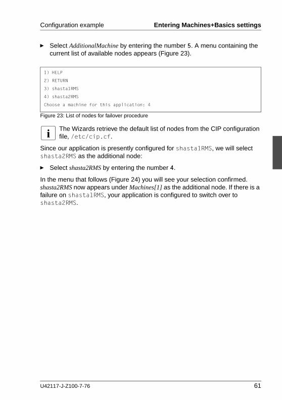
Configuration example Entering Machines+Basics settings
Ê Select AdditionalMachine by entering the number 5. A menu containing the current list of available nodes appears (Figure 23).
Figure 23: List of nodes for failover procedure
I The Wizards retrieve the default list of nodes from the CIP configuration file, /etc/cip.cf.
Since our application is presently configured for shasta1RMS, we will select shasta2RMS as the additional node:
Ê Select shasta2RMS by entering the number 4.
In the menu that follows (Figure 24) you will see your selection confirmed. shasta2RMS now appears under Machines[1] as the additional node. If there is a failure on shasta1RMS, your application is configured to switch over to shasta2RMS.
1) HELP
2) RETURN
3) shasta1RMS
4) shasta2RMS
Choose a machine for this application: 4
U42117-J-Z100-7-76 61

Entering Machines+Basics settings Configuration example
Figure 24: Machines+Basics menu for additional nodes
At this point, the default value of No is specified for 16) AutoSwitchOver. This means that to actually switch your application over, manual action would be required.
Ê To have the switchover procedure carried out automatically, select 16) AutoSwitchOver
The Set flags for AutoSwitchOver menu opens (Figure 25).
Figure 25: AutoSwitchOver mode
Consistency check ...
Machines+Basics (app1:consistent)
Choose the setting to process: 16
1) HELP
2) -
3) SAVE+EXIT
4) REMOVE+EXIT
5) AdditionalMachine
6) AdditionalConsole
7) Machines[0]=shasta1RMS
8) Machines[1]=shasta2RMS
9) (PreCheckScript=)
10) (PreOnlineScript=)
11) (PostOnlineScript=)
12) (PreOfflineScript=)
13) (OfflineDoneScript=)
14) (FaultScript=)
15) (AutoStartUp=no)
16) (AutoSwitchOver=No)
17) (PreserveState=no)
18) (PersistentFault=0)
19) (ShutdownPriority=)
20) (OnlinePriority=)
21) (StandbyTransitions=)
22) (LicenseToKill=no)
23) (AutoBreak=yes)
24) (HaltFlag=no)
25) (PartialCluster=0)
26) (ScriptTimeout=)
Set flags for AutoSwitchOver: Currently set: NO (N)
1) HELP
2) -
3) SAVE+RETURN
4) DEFAULT
5) NO(N)
6) HOSTFAILURE(H)
7) RESOURCEFAILURE(R)
8) SHUTDOWN(S)
Choose one of the flags: 6
62 U42117-J-Z100-7-76

Configuration example Entering Machines+Basics settings
Ê Set a flag by entering the number 6 for HOSTFAILURE. This means that RMS switches an application to another node automatically in the case of a node failure.
The first line of the updated menu indicates the HOSTFAILURE flag is now set (Figure 26).
Figure 26: Setting flags for AutoSwitchOver mode
Continue with the following operations from the same menu:
Ê Enter the number 7 for RESOURCEFAILURE. This means that RMS switches an application to another node automatically in the case of a resource failure.
Ê Enter the number 3 for SAVE+RETURN.
Set flags for AutoSwitchOver: Currently set: HOSTFAILURE (H)
1) HELP
2) -
3) SAVE+RETURN
4) DEFAULT
5) NO(N)
6) NOT:HOSTFAILURE(H)
7) RESOURCEFAILURE(R)
8) SHUTDOWN(S)
Choose one of the flags:
U42117-J-Z100-7-76 63

Entering Machines+Basics settings Configuration example
You will be returned to the Machines+Basics menu (Figure 27). Note that item 16 now displays the AutoSwitchOver flags you just set.
Figure 27: Saving settings
Save your settings now to complete the Application-Create process.
Ê Select SAVE+EXIT by entering the number 3.
Consistency check ...
Machines+Basics (app1:consistent)
1) HELP
2) -
3) SAVE+EXIT
4) REMOVE+EXIT
5) AdditionalMachine
6) AdditionalConsole
7) Machines[0]=shasta1RMS
8) Machines[1]=shasta2RMS
9) (PreCheckScript=)
10) (PreOnlineScript=)
11) (PostOnlineScript=)
12) (PreOfflineScript=)
13) (OfflineDoneScript=)
14) (FaultScript=)
15) (AutoStartUp=no)
16) (AutoSwitchOver=HostFailure|ResourceFailure)
17) (PreserveState=no)
18) (PersistentFault=0)
19) (ShutdownPriority=)
20) (OnlinePriority=)
21) (StandbyTransitions=)
22) (LicenseToKill=no)
23) (AutoBreak=yes)
24) (HaltFlag=no)
25) (PartialCluster=0)
26) (ScriptTimeout=)
Choose the setting to process: 3
64 U42117-J-Z100-7-76

Configuration example Entering non-basic settings
4.6 Entering non-basic settings
The DEMO turnkey wizard performs another consistency check before returning you to the wizard settings menu (Figure 28).
Figure 28: Non-basic settings
I The list of available subapplications displayed in the menu depends on the packages installed on the local system. Some of the subapplications shown in this example may not be available in your market or for your platform.
The menu header indicates there is at least one more setting to specify, but it is not a basic setting.
As described earlier, this application creates an animated graphical picture on an X-window display. Therefore, a display setting for the DEMO wizard must be added to the basic settings you have already entered.
Ê Select DEMO by entering the number 9. The CommandLines menu appears (Figure 29).
Consistency check ...
Yet to do: process at least one of the non-basic settings
Settings of turnkey wizard "DEMO"
Choose the setting to process: 9
1) HELP
2) -
3) SAVE+EXIT
4) -
5) ApplicationName=APP1
6) Machines+Basics(app1)
7) CommandLines(-)
8) Controllers(-)
9) DEMO(-)
10) LocalFileSystems(-)
11) RemoteFileSystems(-)
12) IpAddresses(-)
13) RawDisks(-)
14) RC-VolumeManagement(-)
15) VERITAS-VolumeManagement(-)
16) EMC-RdfManagement(-)
17) FibreCat-MirrorView(-)
18) Gds:Global-Disk-Services(-)
19) Gls:Global-Link-Services(-)
U42117-J-Z100-7-76 65

Entering non-basic settings Configuration example
Figure 29: Prompting for display specification
The menu header indicates that a display still needs to be specified, and the status line tells you that APP1 is not yet consistent; that is, APP1 could not yet run with the present mydemo configuration.
Because the DEMO wizard has been customized for demonstration purposes, some of the items in the menu have been predefined. Items in the menu body indicate the scripts provided by the wizard for starting, stopping, and checking: see the lines beginning with 6) StartCommands[0]=, 7) StopCommands[0]=, and 8) CheckCommands[0]=.
I For technical reasons, spaces are displayed as tildes (~) within the wizard menu commands. The actual commands do not have tildes.
Consistency check ...
Yet to do: set a display
CommandLines (Dem_APP1:not yet consistent)
1) HELP
2) -
3) SAVE+EXIT
4) REMOVE+EXIT
5) Display=
6) StartCommands[0]='hvexec~-F~demo~-c'
7) StopCommands[0]='hvexec~-F~demo~-u'
8) CheckCommands[0]=hvdet_demo
9) (Timeout=300)
10) (AutoRecover=no)
11) (MonitorOnly=no)
Choose the setting to process: 5
66 U42117-J-Z100-7-76

Configuration example Specifying a display
4.7 Specifying a display
Specify the display within the CommandLines menu as follows:
Ê Select Display by entering the number 5. A list of display options appears (Figure 30).
Figure 30: List of display options
You can choose from the list of detected hosts (all hosts in /etc/hosts), or you can select 3) FREECHOICE to specify an arbitrary host with a suitable display.
Ê Select FREECHOICE by entering the number 3.
At the >> prompt, enter the host name or IP address for the X-window display. In this example, we use the IP address 172.25.220.27, but you should enter an address in your LAN.
Completing the FREECHOICE step initiates another consistency check (Figure 31).
1) HELP
2) RETURN
3) FREECHOICE
4) shasta3ADM
5) shasta1ADM
6) shasta2ADM
7) shastaRCA
8) shastaSCON
9) shasta1
10) shasta2
11) shasta1RMS
12) shasta2RMS
Choose a display for this application: 3
>> 172.25.220.27
U42117-J-Z100-7-76 67

Specifying a display Configuration example
Figure 31: Successful consistency check for APP1
The consistency check is successful: you can now use RMS to run APP1 with the mydemo configuration.
Note that the wizard updated the display information for the scripts in items 6) StartCommands[0] and 7) StopCommands[0].
This completes the specification of the non-basic settings. You can now save the non-basic settings and exit this part of the configuration procedure.
Ê From the CommandLines menu (Figure 31), select SAVE+EXIT by entering the number 3.
This will take you back to the Settings of turnkey wizard "DEMO" menu (Figure 32).
Consistency check ...
CommandLines (Dem_APP1:consistent)
1) HELP
2) -
3) SAVE+EXIT
4) REMOVE+EXIT
5) Display=172.25.220.27
6) StartCommands[0]='hvexec~-F~demo~-c~~172.25.220.27'
7) StopCommands[0]='hvexec~-F~demo~-u~~172.25.220.27'
8) CheckCommands[0]=hvdet_demo
9) (Timeout=300)
10) (AutoRecover=no)
11) (MonitorOnly=no)
Choose the setting to process: 3
68 U42117-J-Z100-7-76

Configuration example Specifying a display
Figure 32: Turnkey wizard DEMO
By specifying the basic and non-basic settings for your application and achieving a consistent result, you have successfully finished the Application-Create part of the configuration procedure.
Ê Select SAVE+EXIT by entering the number 3. This will take you back to the RMS configuration menu.
Consistency check ...
Settings of turnkey wizard "DEMO"
Choose the setting to process: 3
1) HELP
2) -
3) SAVE+EXIT
4) -
5) ApplicationName=APP1
6) Machines+Basics(app1)
7) CommandLines(-)
8) Controllers(-)
9) DEMO(Dem_APP1)
10) LocalFileSystems(-)
11) RemoteFileSystems(-)
12) IpAddresses(-)
13) RawDisks(-)
14) RC-VolumeManagement(-)
15) VERITAS-VolumeManagement(-)
16) EMC-RdfManagement(-)
17) FibreCat-MirrorView(-)
18) Gds:Global-Disk-Services(-)
19) Gls:Global-Link-Services(-)
U42117-J-Z100-7-76 69

Activating the configuration Configuration example
4.8 Activating the configuration
As described in the section “General configuration procedure” on page 34, activating a configuration is the third of the four fundamental steps required to set up a high-availability configuration.
You must stop RMS before activating a configuration. In this example, we stopped RMS before creating the configuration.
The starting point for the activation phase is the Main configuration menu (Figure 33).
Figure 33: Main configuration menu
Ê Select Configuration-Activate by entering the number 8.
No further input is required at this stage. As the Wizard completes each task in the activation phase, it displays status information as described in the section “Activating a configuration” on page 44. You will be prompted to continue at the end of the process (see Figure 34).
Figure 34: Successful configuration activation
shasta1: Main configuration menu, current configuration: mydemo
No RMS active in the cluster
Choose an action: 8
1) HELP
2) QUIT
3) Application-Create
4) Application-Edit
5) Application-Remove
6) Application-Clone
7) Configuration-Generate
8) Configuration-Activate
9) Configuration-Copy
10) Configuration-Remove
11) Configuration-Freeze
12) Configuration-Thaw
13) Configuration-Edit-Global-Settings
14) Configuration-Consistency-Report
15) Configuration-ScriptExecution
16) RMS-CreateMachine
17) RMS-RemoveMachine
The new configuration was distributed successfully.
About to put the new configuration in effect ... done.
The activation has finished successfully.
Hit CR to continue
70 U42117-J-Z100-7-76

Configuration example Activating the configuration
Ê Press the [Enter] or [Return] key to return to the Main configuration menu (Figure 35).
Figure 35: Quitting the Main configuration menu
Ê Select QUIT by entering the number 2.
This ends the activation phase of the configuration process. At this point, RMS may be started to monitor the newly-configured application.
shasta1: Main configuration menu, current configuration: mydemo
No RMS active in the cluster
Choose an action: 2
1) HELP
2) QUIT
3) Application-Create
4) Application-Edit
5) Application-Remove
6) Application-Clone
7) Configuration-Generate
8) Configuration-Activate
9) Configuration-Copy
10) Configuration-Remove
11) Configuration-Freeze
12) Configuration-Thaw
13) Configuration-Edit-Global-Settings
14) Configuration-Consistency-Report
15) Configuration-ScriptExecution
16) RMS-CreateMachine
17) RMS-RemoveMachine
U42117-J-Z100-7-76 71

Creating a second application Configuration example
4.9 Creating a second application
In this section, the mydemo configuration is expanded by adding a second appli-cation. This example application differs from the first because duplicate config-uration procedures are skipped to simplify the example. However, in other parts of the procedure, new features add to the complexity of the mydemo configu-ration.
The second application differs from the first as follows:
● The application uses a new application type, GENERIC, instead of DEMO. We will use the name APP2 for the second application.
● APP2 will control the first application (APP1). Therefore, APP2 must be configured with a controller sub-application.
Resume the configuration procedure as follows:
Ê Stop RMS if it is running.
Ê Return to the Main configuration menu with the following command:
# hvw -n mydemo
The Main configuration menu opens (see Figure 36).
Figure 36: Starting again with the Main configuration menu
You can add more machines to the cluster at this point, provided the required site preparation steps have been completed.
shasta1: Main configuration menu, current configuration: mydemo
No RMS active in the cluster
Choose an action: 3
1) HELP
2) QUIT
3) Application-Create
4) Application-Edit
5) Application-Remove
6) Application-Clone
7) Configuration-Generate
8) Configuration-Activate
9) Configuration-Copy
10) Configuration-Remove
11) Configuration-Freeze
12) Configuration-Thaw
13) Configuration-Edit-Global-Settings
14) Configuration-Consistency-Report
15) Configuration-ScriptExecution
16) RMS-CreateMachine
17) RMS-RemoveMachine
72 U42117-J-Z100-7-76

Configuration example Creating a second application
Ê To add machines, select RMS-CreateMachine by entering the number 16. Follow the procedure described earlier and then return to the Main configuration menu when finished.
Ê From the Main configuration menu, select Application-Create by entering the number 3.
The Application type selection menu opens (see Figure 37).
Figure 37: Application type selection menu
This time, assign the GENERIC application type to the application. This means that the GENERIC turnkey wizard will be in charge of the configuration procedure.
Ê Select the GENERIC application type by entering the number 6.
After the consistency check, you are prompted to configure the basic settings. APP2 is the default value for the application name.
I If you want to change the name, select 5) ApplicationName (see Figure 38).
Creation: Application type selection menu:
1) HELP
2) QUIT
3) RETURN
4) OPTIONS
5) DEMO
6) GENERIC
7) LIVECACHE
8) R3ANY
9) R3CI
10) RTP
Application Type: 6
U42117-J-Z100-7-76 73

Creating a second application Configuration example
Figure 38: Prompting for further specification
Ê Select Machines+Basics by entering the number 7.
The consistency of APP2 is checked, and the result is positive. When the Machines+Basics menu appears, it shows that APP2 is initially configured to run on shasta1RMS (see item 7) Machines[0] in Figure 39).
Figure 39: Machines+Basics menu
Consistency check ...
Yet to do: process the basic settings using Machines+Basics
Yet to do: choose a proper application name
Settings of turnkey wizard "GENERIC"
1) HELP
2) NO-SAVE+EXIT
3) SAVE+EXIT
4) REMOVE+EXIT
5) ApplicationName=APP2
6) BeingControlled=no
7) Machines+Basics(-)
Choose the setting to process: 7
Consistency check ...
Machines+Basics (app2:consistent)
Choose the setting to process: 5
1) HELP
2) -
3) SAVE+EXIT
4) REMOVE+EXIT
5) AdditionalMachine
6) AdditionalConsole
7) Machines[0]=shasta1RMS
8) (PreCheckScript=)
9) (PreOnlineScript=)
10) (PostOnlineScript=)
11) (PreOfflineScript=)
12) (OfflineDoneScript=)
13) (FaultScript=)
14) (AutoStartUp=no)
15) (AutoSwitchOver=No)
16) (PreserveState=no)
17) (PersistentFault=0)
18) (ShutdownPriority=)
19) (OnlinePriority=)
20) (StandbyTransitions=)
21) (LicenseToKill=no)
22) (AutoBreak=yes)
23) (HaltFlag=no)
24) (PartialCluster=0)
25) (ScriptTimeout=)
74 U42117-J-Z100-7-76

Configuration example Creating a second application
Ê Select AdditionalMachine by entering the number 5. A menu appears with the list of available machines (Figure 40).
Figure 40: List of nodes for failover procedure
As with the former application, the additional machine to be specified for the failover procedure is shasta2RMS.
Ê Select shasta2RMS by entering the number 4.
In the screen that follows you see your selection confirmed—menu item 8) Machines[1] now displays shasta2RMS as the additional machine (Figure 41).
Figure 41: Machines+Basics menu
1) HELP
2) RETURN
3) shasta1RMS
4) shasta2RMS
Choose a machine for this application: 4
Consistency check ...
Machines+Basics (app2:consistent)
Choose the setting to process: 3
1) HELP
2) -
3) SAVE+EXIT
4) REMOVE+EXIT
5) AdditionalMachine
6) AdditionalConsole
7) Machines[0]=shasta1RMS
8) Machines[1]=shasta2RMS
9) (PreCheckScript=)
10) (PreOnlineScript=)
11) (PostOnlineScript=)
12) (PreOfflineScript=)
13) (OfflineDoneScript=)
14) (FaultScript=)
15) (AutoStartUp=no)
16) (AutoSwitchOver=No)
17) (PreserveState=no)
18) (PersistentFault=0)
19) (ShutdownPriority=)
20) (OnlinePriority=)
21) (StandbyTransitions=)
22) (LicenseToKill=no)
23) (AutoBreak=yes)
24) (HaltFlag=no)
25) (PartialCluster=0)
26) (ScriptTimeout=)
U42117-J-Z100-7-76 75

Setting up a controlling application Configuration example
Note that item 16 indicates AutoSwitchOver=No, so APP2 will not be switched automatically to shasta2RMS if shasta1RMS fails: it must be switched manually with the GUI or CLI. To enable automatic switchover, select item 16.
Save your settings and exit this part of the configuration procedure:
Ê Select SAVE+EXIT by entering the number 3. This takes you to the non-basic settings menu.
4.10 Setting up a controlling application
The basic settings have been specified. However, we still need to set up APP2 to control APP1. This will involve the following two steps, available in the non-basic settings:
● Create a controller object for APP2.
● Specify APP1 as the application to be controlled.
The previous step has taken you to the non-basic settings menu (Figure 42).
Figure 42: Non-basic settings
Ê Select Controllers by entering the number 8.
This creates a controller object for APP2 and presents a menu that lets you specify the controller settings (Figure 43).
Consistency check ...
Yet to do: process at least one of the non-basic settings
Settings of turnkey wizard "GENERIC"
Choose the setting to process: 8
1) HELP
2) -
3) SAVE+EXIT
4) -
5) ApplicationName=APP2
6) Machines+Basics(app2)
7) CommandLines(-)
8) Controllers(-)
9) LocalFileSystems(-)
10) RemoteFileSystems(-)
11) IpAddresses(-)
12) RawDisks(-)
13) RC-VolumeManagement(-)
14) VERITAS-VolumeManagement(-)
15) EMC-RdfManagement(-)
16) FibreCat-MirrorView(-)
17) Gds:Global-Disk-Services(-)
18) Gls:Global-Link-Services(-)
76 U42117-J-Z100-7-76
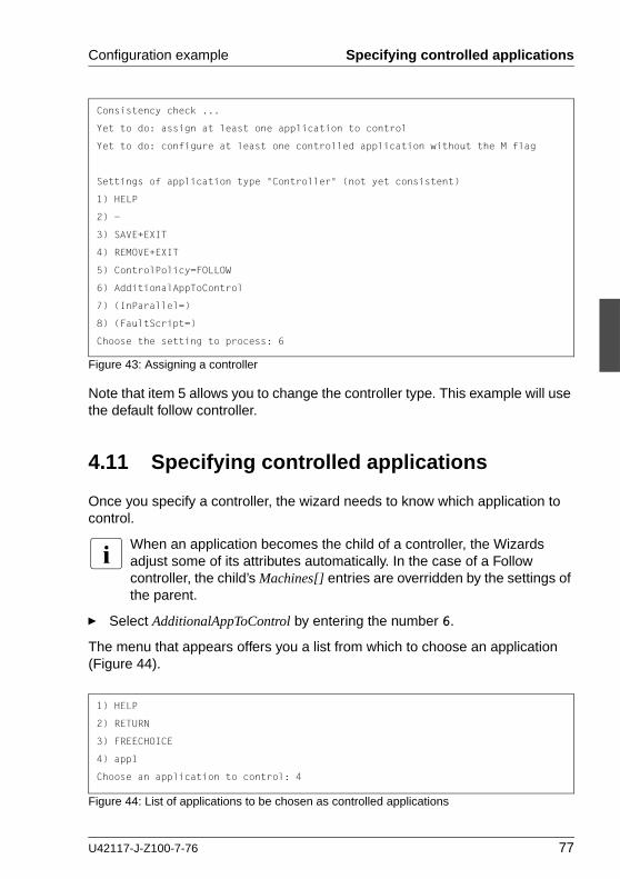
Configuration example Specifying controlled applications
Figure 43: Assigning a controller
Note that item 5 allows you to change the controller type. This example will use the default follow controller.
4.11 Specifying controlled applications
Once you specify a controller, the wizard needs to know which application to control.
I When an application becomes the child of a controller, the Wizards adjust some of its attributes automatically. In the case of a Follow controller, the child’s Machines[] entries are overridden by the settings of the parent.
Ê Select AdditionalAppToControl by entering the number 6.
The menu that appears offers you a list from which to choose an application (Figure 44).
Figure 44: List of applications to be chosen as controlled applications
Consistency check ...
Yet to do: assign at least one application to control
Yet to do: configure at least one controlled application without the M flag
Settings of application type "Controller" (not yet consistent)
1) HELP
2) -
3) SAVE+EXIT
4) REMOVE+EXIT
5) ControlPolicy=FOLLOW
6) AdditionalAppToControl
7) (InParallel=)
8) (FaultScript=)
Choose the setting to process: 6
1) HELP
2) RETURN
3) FREECHOICE
4) app1
Choose an application to control: 4
U42117-J-Z100-7-76 77

Specifying controlled applications Configuration example
The controlled application is APP1, while APP2 is the controlling application. Choose the application to be controlled as follows:
Ê Select APP1 by entering the number 4. The controller flags menu appears (Figure 45).
Figure 45: Menu for setting controller flags
There are a number of flags that can be set for a controlled application. In this example, the A (AUTORECOVER) flag has been set. The A flag means If the controlled application becomes offline, the controlling application tries to restart it. The AUTORECOVER menu item is now in the opposite state; that is, ready to be toggled to NOT.
The T (TIMEOUT) flag limits the amount of time tolerated while bringing the controlled application online. In this example, we will reduce the timeout period to 150 seconds.
Ê Change the timeout period by entering 7.
Ê In the menu that appears (Figure 46), select FREECHOICE by entering the number 3.
Figure 46: Changing controller timeout period
Ê At the >> prompt, enter 150 for the timeout period.
Set flags for (sub) application: app1
Currently set: AUTORECOVER,TIMEOUT (AT180)
1) HELP
2) -
3) SAVE+RETURN
4) DEFAULT
5) MONITORONLY(M)
6) NOT:AUTORECOVER(A)
7) TIMEOUT(T)
Choose one of the flags:
1) HELP
2) RETURN
3) FREECHOICE
4) 180
Set an appropriate timeout: 3
>> 150
78 U42117-J-Z100-7-76

Configuration example Specifying controlled applications
Ê Press [Enter] or [Return] to return to the menu for controller flags (Figure 47).
Figure 47: Saving flags for controller
After completing the settings, save them and return to the Controllers menu as follows:
Ê Select SAVE+RETURN by entering the number 3.
The Controllers menu shows that the controller settings are now consistent (Figure 48).
Figure 48: Indication of flags set for controller
Note that your settings are confirmed on item 7) Controllers[0]: the A and T flags have been set for APP1.
Set flags for (sub) application: app1
Currently set: AUTORECOVER,TIMEOUT (AT150)
1) HELP
2) -
3) SAVE+RETURN
4) DEFAULT
5) MONITORONLY(M)
6) NOT:AUTORECOVER(A)
7) TIMEOUT(T)
Choose one of the flags: 3
Consistency check ...
Settings of application type "Controller" (consistent)
1) HELP
2) -
3) SAVE+EXIT
4) REMOVE+EXIT
5) ControlPolicy=FOLLOW
6) AdditionalAppToControl
7) Controllers[0]=AT150:app1
8) (InParallel=)
9) (FaultScript=)
Choose the setting to process: 3
U42117-J-Z100-7-76 79

Specifying controlled applications Configuration example
Ê Select SAVE+EXIT by entering the number 3.
This takes you back to the GENERIC menu (Figure 49).
Figure 49: Menu with settings for GENERIC turnkey wizard
In the GENERIC menu, item 8 Controllers now displays a controller assigned to APP2.
Ê Select SAVE+EXIT by entering the number 3. This takes you back to the Main configuration menu (Figure 50).
Figure 50: Main configuration menu
This completes the creation of the second application.
Consistency check ...
Settings of turnkey wizard "GENERIC"
Choose the setting to process: 3
1) HELP
2) -
3) SAVE+EXIT
4) -
5) ApplicationName=APP2
6) Machines+Basics(app2)
7) CommandLines(-)
8) Controllers(Ctl_APP2)
9) LocalFileSystems(-)
10) RemoteFileSystems(-)
11) IpAddresses(-)
12) RawDisks(-)
13) RC-VolumeManagement(-)
14) VERITAS-VolumeManagement(-)
15) EMC-RdfManagement(-)
16) FibreCat-MirrorView(-)
17) Gds:Global-Disk-Services(-)
18) Gls:Global-Link-Services(-)
shasta1: Main configuration menu, current configuration: mydemo
No RMS active in the cluster
Choose an action:
1) HELP
2) QUIT
3) Application-Create
4) Application-Edit
5) Application-Remove
6) Application-Clone
7) Configuration-Generate
8) Configuration-Activate
9) Configuration-Copy
10) Configuration-Remove
11) Configuration-Freeze
12) Configuration-Thaw
13) Configuration-Edit-Global-Settings
14) Configuration-Consistency-Report
15) Configuration-ScriptExecution
16) RMS-CreateMachine
17) RMS-RemoveMachine
80 U42117-J-Z100-7-76
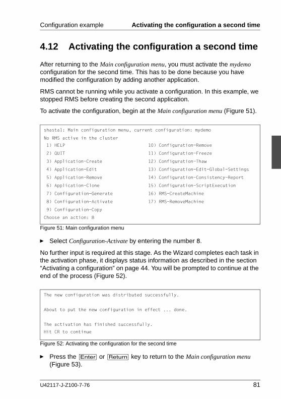
Configuration example Activating the configuration a second time
4.12 Activating the configuration a second time
After returning to the Main configuration menu, you must activate the mydemo configuration for the second time. This has to be done because you have modified the configuration by adding another application.
RMS cannot be running while you activate a configuration. In this example, we stopped RMS before creating the second application.
To activate the configuration, begin at the Main configuration menu (Figure 51).
Figure 51: Main configuration menu
Ê Select Configuration-Activate by entering the number 8.
No further input is required at this stage. As the Wizard completes each task in the activation phase, it displays status information as described in the section “Activating a configuration” on page 44. You will be prompted to continue at the end of the process (Figure 52).
Figure 52: Activating the configuration for the second time
Ê Press the [Enter] or [Return] key to return to the Main configuration menu (Figure 53).
shasta1: Main configuration menu, current configuration: mydemo
No RMS active in the cluster
Choose an action: 8
1) HELP
2) QUIT
3) Application-Create
4) Application-Edit
5) Application-Remove
6) Application-Clone
7) Configuration-Generate
8) Configuration-Activate
9) Configuration-Copy
10) Configuration-Remove
11) Configuration-Freeze
12) Configuration-Thaw
13) Configuration-Edit-Global-Settings
14) Configuration-Consistency-Report
15) Configuration-ScriptExecution
16) RMS-CreateMachine
17) RMS-RemoveMachine
The new configuration was distributed successfully.
About to put the new configuration in effect ... done.
The activation has finished successfully.
Hit CR to continue
U42117-J-Z100-7-76 81

Starting RMS Configuration example
Figure 53: Return to Main configuration menu
Ê Select QUIT by entering the number 2.
This ends the activation phase of the configuration process.
4.13 Starting RMS
At this point, you are ready to start RMS on all nodes in the cluster to monitor both applications.You can use the Cluster Admin GUI (see the section “Starting RMS” on page 137) or you can enter the following command from any machine in the cluster:
# hvcm -a mydemo
Note that you do not have to specify “mydemo” on the hvcm command line if it is the configuration that was most recently activated.
This ends the configuration example.
shasta1: Main configuration menu, current configuration: mydemo
No RMS active in the cluster
Choose an action: 2
1) HELP
2) QUIT
3) Application-Create
4) Application-Edit
5) Application-Remove
6) Application-Clone
7) Configuration-Generate
8) Configuration-Activate
9) Configuration-Copy
10) Configuration-Remove
11) Configuration-Freeze
12) Configuration-Thaw
13) Configuration-Edit-Global-Settings
14) Configuration-Consistency-Report
15) Configuration-ScriptExecution
16) RMS-CreateMachine
17) RMS-RemoveMachine
82 U42117-J-Z100-7-76

U42117-J-Z100-7-76
Part II: Administration


5 Using the Cluster Admin GUIThis chapter describes PRIMECLUSTER administration using the Cluster Admin graphical user interface (GUI). In addition, some command-line interface (CLI) commands are discussed.
Chapter contents:
● “Overview” on page 85
● “Starting the Cluster Admin GUI” on page 86
● “Monitoring RMS with Cluster Admin” on page 92
5.1 Overview
RMS administration can be done by means of the Cluster Admin GUI or by the CLI. The procedures in this chapter focus on the Cluster Admin GUI.
Most of the GUI examples in this chapter show clusters with typical PRIMECLUSTER product installations. The appearance of some tabs and menus in the GUI display will change according to the products installed for your platform or market.
I PRIMECLUSTER Configuration Services (PCS) is not installed when the Wizard Tools are installed.
CLI procedures
Some of the operations described in this chapter describe the equivalent CLI procedure. However, we recommend that the CLI be used only by expert system administrators, or in those cases where a browser is not available. If you decide to use a CLI procedure, please note the following:
● The commands are located in the <RELIANT_PATH>/bin directory.
● All RMS CLI commands accept both CF node names and RMS node names for SysNode objects when the RMS naming convention has been followed (that is, when the names are of the form <CF-name>RMS).
● RMS CLI commands accept case-insensitive application names.
U42117-J-Z100-7-76 85

Starting the Cluster Admin GUI Using the Cluster Admin GUI
● The CLI procedures presented here are not intended to be a complete description of the commands that are employed. Other options may be available. For more information about any CLI command, see its online manual pages. For the complete list of online documentation related to RMS operation, see “Appendix—List of manual pages” on page 223.
CLI status codes
In general, RMS hv* commands send a request to the base monitor and then return immediately without waiting for this request to be processed. They exit with a status code of 0 (success), which indicates a request has been sent to the base monitor successfully. However, this does not guarantee that the request was processed successfully.
Important exceptions include the ‘hvshut’ and ‘hvutil -[mM]’ commands, which remove nodes and applications from RMS control. These commands may return status codes that indicate failure. This type of command also provides an option for “forced” operation, but this should be used with great care and only when absolutely necessary.
5.2 Starting the Cluster Admin GUI
The following sections discuss how to use the RMS portion of the GUI.
I Windows desktop systems require the Java® plugin as specified in the PRIMECLUSTER Installation Guide for your operating system.
5.2.1 Web-Based Admin View
Ê Open a Java-enabled browser and enter the following URL in the Address location:
http://<hostname>:8081/Plugin.cgi
The hostname should be the name or IP address of the primary or secondary management server. For example, if a cluster has shasta1 and shasta2 as its primary and secondary management servers, the URL would be either one of the following:
● http://shasta1:8081/Plugin.cgi
● http://shasta2:8081/Plugin.cgi
86 U42117-J-Z100-7-76

Using the Cluster Admin GUI Starting the Cluster Admin GUI
The Plugin.cgi URL always attempts to contact the primary management server; after contacting the host, the browser changes the URL suffix from ‘.cgi’ to ‘.html’. If you instead use the Plugin.html form, Cluster Admin will attempt to make direct contact with the server specified in the URL.
For details on the primary and secondary management servers, refer to the PRIMECLUSTER Installation Guide for your operating system.
5.2.2 Login
Before logging in, make sure you have a user name and password with the appropriate privilege level. Cluster Admin has the following privilege levels:
● Root privileges—Can perform all actions including configuration, adminis-tration, and viewing tasks.
● Administrative privileges—Can view and execute commands, but cannot make configuration changes.
● Operator privileges—Can only perform viewing tasks.
For more details on privilege levels, refer to the PRIMECLUSTER Installation Guide for your operating system.
After the Web-Based Admin View login window appears (Figure 54), log in as follows:
Ê Enter the user name and password for a user with the appropriate privilege level.
Ê Click the OK button.
Figure 54: Web-Based Admin View login
After you log in, the Web-Based Admin View window appears (Figure 55).
U42117-J-Z100-7-76 87

Starting the Cluster Admin GUI Using the Cluster Admin GUI
Figure 55: Invoking the Cluster Services GUI
Ê Click the Global Cluster Services button to advance to the next view (Figure 56).
Figure 56: Invoking Cluster Admin
Ê Click the Cluster Admin button.
88 U42117-J-Z100-7-76

Using the Cluster Admin GUI Starting the Cluster Admin GUI
The Choose a node for initial connection window appears (Figure 57).
Figure 57: Cluster Admin initial connection menu
The nodes are displayed in alphabetical order, and the first one is selected by default. In most cases, the node you choose is immaterial for administrative tasks.
Ê Select the desired node for the connection, and click OK.
The next window that appears depends on how you have set the trust levels for the Cluster Admin Java applets. If you have already chosen to use trusted applets for all sessions, you can skip the following description.
Trusted applets
For platform independence and security, the Cluster Admin GUI uses Java applets. When the Java applets run in trusted mode, they are allowed to use some client system resources, such as the clipboard. If you intend to copy and paste text between the Java window and other applications on your workstation, you must run the applets in trusted mode.
I PRIMECLUSTER trusted applets are signed by VeriSign, Inc.The first time you start the Cluster Admin applet, a Java Security Warning dialog allows you to choose the security level for the current and future sessions.
U42117-J-Z100-7-76 89

Starting the Cluster Admin GUI Using the Cluster Admin GUI
5.2.3 Main Cluster Admin window
When Cluster Admin opens, the initial view is similar to Figure 58.
Figure 58: Main Cluster Admin window—Initial view
The following tabs appear at the bottom of the left pane:
● cf
● rms & pcs (or simply rms if PCS is not installed)
● sis
● msg (message window)
Clicking a tab switches the view to the corresponding product. Initially, the CF view is selected. All views have the following common features:
● Menu bar—The pull-down menus contain generic administrative functions as well as items specific to the PRIMECLUSTER products. Some entries may be disabled (grayed out) according to the item selected in the current view.
90 U42117-J-Z100-7-76

Using the Cluster Admin GUI Starting the Cluster Admin GUI
● Configuration tree—The left pane contains product-specific configuration information in a hierarchical display. Clicking on an item in the tree will display the item’s properties and, in some views, allow you to change them. Right-clicking on an item generally brings up a context menu specific to that item.
● Input and message area—The large pane on the right is the main work and information area. The content varies according to the product being admin-istered and the functions selected from the menus or tree.
This chapter focuses on RMS administration. For information about operations available on the other tabs, refer to the corresponding product documentation.
5.2.4 Cluster Admin message view
Error and debug messages related to Cluster Admin can be displayed at any time:
Ê Click the msg tab on the bottom of the RMS tree pane. (The tab label is red if a new message has been added to the text area since it was last viewed.) The Admin Errors and Messages view appears (Figure 59).
Figure 59: Main Cluster Admin window—message view
U42117-J-Z100-7-76 91
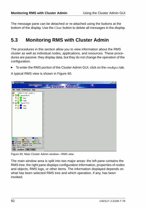
Monitoring RMS with Cluster Admin Using the Cluster Admin GUI
The message pane can be detached or re-attached using the buttons at the bottom of the display. Use the Clear button to delete all messages in the display.
5.3 Monitoring RMS with Cluster Admin
The procedures in this section allow you to view information about the RMS cluster as well as individual nodes, applications, and resources. These proce-dures are passive: they display data, but they do not change the operation of the configuration.
Ê To enter the RMS portion of the Cluster Admin GUI, click on the rms&pcs tab.
A typical RMS view is shown in Figure 60.
Figure 60: Main Cluster Admin window—RMS view
The main window area is split into two major areas: the left pane contains the RMS tree; the right pane displays configuration information, properties of nodes and objects, RMS logs, or other items. The information displayed depends on what has been selected RMS tree and which operation, if any, has been invoked.
92 U42117-J-Z100-7-76

Using the Cluster Admin GUI Monitoring RMS with Cluster Admin
5.3.1 RMS tree
The Cluster Admin RMS tree displays the configuration information for the cluster in a simple hierarchical format. The tree has the following levels:
● Root of the tree—Represents the cluster. The root is labeled with the cluster name, followed by the RMS configuration name in parentheses. The cluster name is determined by your CF configuration.
● First level—Represents the system nodes forming the cluster.
● Second level—Represents the userApplication objects running on each of the system nodes.
● Third level—Represents subapplications, if any. Also contains non-affiliated groups of objects (see fourth level description).
● Fourth level—Represents the resources necessary for each of the subappli-cations. Also contains non-affiliated objects.
I Non-affiliated andOP and orOP objects are intended for use by RMS experts. These items provide logical dependencies and group connectivity between nodes, applications, and subapplications.
If an application has subapplications, the fourth level represents resources used by that subapplication. If an application does not have subapplications, then the third level represents all the resources used by the userApplication.
Applications always appear at the second level of the tree, even if some of them are controlled by others. Dependencies between applications are depicted in the RMS tree by the presence of controller objects. An example of an RMS tree with a controller object is shown in Figure 61.
U42117-J-Z100-7-76 93

Monitoring RMS with Cluster Admin Using the Cluster Admin GUI
Figure 61: RMS tree with a controller object
In the example shown in the figure, the Resource attribute of the highlighted controller object in App1 contains the name of the App2 application: this indicates the dependence of App1 on App2.
A complete visual display of object dependence is available from the RMS graph. See the section “Using RMS graphs” on page 107 for a description of the procedure.
94 U42117-J-Z100-7-76

Using the Cluster Admin GUI Monitoring RMS with Cluster Admin
5.3.2 Pop-up context menus
Each object in the Cluster Admin RMS configuration tree has a pop-up context menu that provides quick access to commonly-used operations. Invoke the context menu by right-clicking on any object. The first item on the menu displays the selected object’s name in grayed-out text. The remaining items list the available operations, which vary according to the object’s type and current state (Figure 62).
Figure 62: Pop-up context menu for a node
Items that affect object states, node states, or the entire RMS configuration appear toward the bottom of the menu. These actions are described in the final sections of this chapter.
I The PRIMECLUSTER Configuration Services (PCS) item on node context menus (shown at the bottom of the menu in the above figure) will not appear if the RMS Wizard Tools are installed.
I To close the context menu without performing an operation, click the grayed-out object name in the menu or press the [Esc] key.
The menu offers different operations for a node object compared to an appli-cation object. It also offers different options for an application object in the online state (Figure 63) compared to the offline state (Figure 64).
U42117-J-Z100-7-76 95

Monitoring RMS with Cluster Admin Using the Cluster Admin GUI
Figure 63: Pop-up context menu for an online application
Figure 64: Pop-up context menu for an offline application
96 U42117-J-Z100-7-76

Using the Cluster Admin GUI Monitoring RMS with Cluster Admin
5.3.3 Pop-up confirmation dialogs
When you select an item in an object’s context menu that can cause state changes to that object, a pop-up confirmation dialog appears (Figure 65). To proceed with the action described in the warning message, click Yes; to cancel the action, click No.
Figure 65: Pop-up confirmation dialog
5.3.4 Displaying environment variables
Display the global (clusterwide) environment variables as follows:
Ê Right-click on a cluster in the RMS tree window and select View Environment from the context menu (Figure 66).
Figure 66: Displaying global environment variables
The global variables will appear under a separate tab in the right pane (Figure 67).
U42117-J-Z100-7-76 97

Monitoring RMS with Cluster Admin Using the Cluster Admin GUI
Figure 67: Global environment variable view
I To close a tab view, use the button in the upper-right corner of the view.
Display local environment variables as follows:
Ê Right-click on a node in the RMS tree window and select View Environment from the context menu (Figure 68).
Figure 68: Displaying local environment variables
98 U42117-J-Z100-7-76

Using the Cluster Admin GUI Monitoring RMS with Cluster Admin
Both local and global variables appear on the same tab in the right pane (Figure 69).
Figure 69: Local environment variables view
CLI: hvdisp
Display the environment variables with the hvdisp command, which does not require root privilege:
hvdisp ENV
hvdisp ENVL
5.3.5 Displaying object states
The state of each RMS object is indicated by the color of its circular status icon, located immediately to the left of the object’s name in the configuration tree. The legend for the object states appears below the RMS tree in the left pane of the RMS view (Figure 70).
U42117-J-Z100-7-76 99

Monitoring RMS with Cluster Admin Using the Cluster Admin GUI
Figure 70: Displaying application and object states
In the example above, the application App2 is online (green status icon) on node shasta1RMS, but offline (blue status icon) on node shasta2RMS.
See “Appendix—States” on page 189 for a description of RMS object states.
CLI: hvdisp
The syntax for the CLI is as follows:
hvdisp {-a | -c} [-o out_file]
Options:
The hvdisp command only works when RMS is running and does not require root privilege.
-a Displays the object name, the object type, the object’s SysNode name, and the object state for each object in the configuration (automatically generated connectors are not shown)
-c Displays information in compact format
-o Sends the output to the designated file
100 U42117-J-Z100-7-76

Using the Cluster Admin GUI Monitoring RMS with Cluster Admin
5.3.6 Configuration information or object attributes
View configuration information for individual objects by left-clicking with the mouse on the object in the tree. The properties are displayed in a tabular format on the right pane of the RMS main window (Figure 71).
Figure 71: Configuration information or object attributes
U42117-J-Z100-7-76 101

Monitoring RMS with Cluster Admin Using the Cluster Admin GUI
102 U42117-J-Z100-7-76

6 Additional administrative toolsThe Cluster Admin GUI provides several additional tools to help you manage RMS operation.
Chapter contents:
● “Using the RMS clusterwide table” on page 103
● “Using RMS graphs” on page 107
● “Interpreting display changes” on page 122
● “Viewing RMS log messages” on page 126
6.1 Using the RMS clusterwide table
The RMS clusterwide table displays the state of each application on each of the system nodes in a concise table.
Ê To open the clusterwide table, right-click the cluster name (the root of the RMS tree in the left pane) and then select View Cluster Wide table from the context menu (Figure 72).
Figure 72: Opening the clusterwide table
The clusterwide table appears in a separate window (Figure 73).
Figure 73: Clusterwide table
U42117-J-Z100-7-76 103
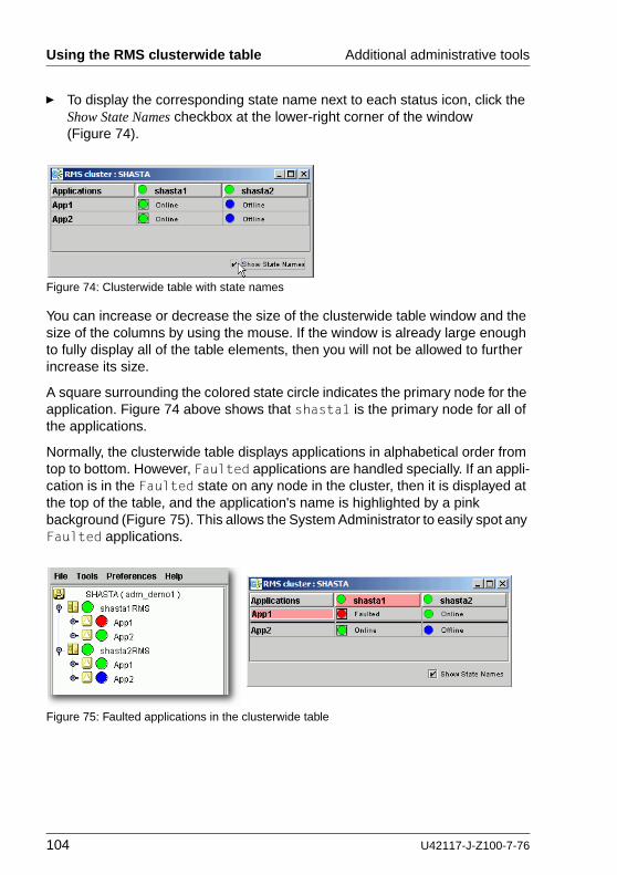
Using the RMS clusterwide table Additional administrative tools
Ê To display the corresponding state name next to each status icon, click the Show State Names checkbox at the lower-right corner of the window (Figure 74).
Figure 74: Clusterwide table with state names
You can increase or decrease the size of the clusterwide table window and the size of the columns by using the mouse. If the window is already large enough to fully display all of the table elements, then you will not be allowed to further increase its size.
A square surrounding the colored state circle indicates the primary node for the application. Figure 74 above shows that shasta1 is the primary node for all of the applications.
Normally, the clusterwide table displays applications in alphabetical order from top to bottom. However, Faulted applications are handled specially. If an appli-cation is in the Faulted state on any node in the cluster, then it is displayed at the top of the table, and the application's name is highlighted by a pink background (Figure 75). This allows the System Administrator to easily spot any Faulted applications.
Figure 75: Faulted applications in the clusterwide table
104 U42117-J-Z100-7-76
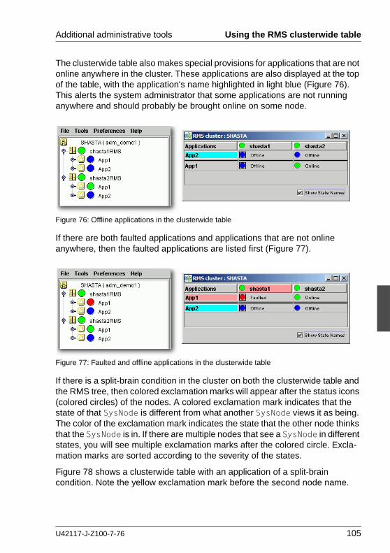
Additional administrative tools Using the RMS clusterwide table
The clusterwide table also makes special provisions for applications that are not online anywhere in the cluster. These applications are also displayed at the top of the table, with the application's name highlighted in light blue (Figure 76). This alerts the system administrator that some applications are not running anywhere and should probably be brought online on some node.
Figure 76: Offline applications in the clusterwide table
If there are both faulted applications and applications that are not online anywhere, then the faulted applications are listed first (Figure 77).
Figure 77: Faulted and offline applications in the clusterwide table
If there is a split-brain condition in the cluster on both the clusterwide table and the RMS tree, then colored exclamation marks will appear after the status icons (colored circles) of the nodes. A colored exclamation mark indicates that the state of that SysNode is different from what another SysNode views it as being. The color of the exclamation mark indicates the state that the other node thinks that the SysNode is in. If there are multiple nodes that see a SysNode in different states, you will see multiple exclamation marks after the colored circle. Excla-mation marks are sorted according to the severity of the states.
Figure 78 shows a clusterwide table with an application of a split-brain condition. Note the yellow exclamation mark before the second node name.
U42117-J-Z100-7-76 105

Using the RMS clusterwide table Additional administrative tools
Figure 78: Split-brain conditions in the clusterwide table
I Momentary split-brain conditions may be indicated while a node starts up or shuts down.
6.1.1 Using context menus from the clusterwide table
Each object in the clusterwide table has a pop-up context menu that provides quick access to commonly-used operations.
Ê To display a context menu, right-click on any object with a status icon, where column headers represent hosts and cells represent applications.
The first item on the menu displays the selected object’s name in grayed-out text. The remaining items list the available operations, which vary according to the object’s type and current state (Figure 79).
Figure 79: Using context menus in the clusterwide table
Items that affect object states, node states, or the entire RMS configuration appear toward the bottom of the menu. These actions are described in the final sections of this chapter.
106 U42117-J-Z100-7-76

Additional administrative tools Using RMS graphs
Ê To close the context menu without performing an operation, click the grayed-out object name in the menu or press the [Esc] key.
6.2 Using RMS graphs
Cluster Admin provides an alternate way of viewing the RMS configuration hierarchy called graphs. A graph represents the configuration in a true tree structure, where the branches indicate the dependencies that are not generally visible in the RMS configuration tree described earlier. The following types of graphs are available:
● Full graph—Displays the complete cluster configuration.
● Application graph—Shows all of the resources used by an application and can be used to look at specific resource properties.
● Subapplication graph—Lists all of the subapplications used by a given appli-cation, and it shows the connections between the subapplications.
● Composite subapplications graph—Shows all the subapplications that the application depends on directly or indirectly.
The following sections describe each type in more detail, as well as these graph-related features:
● Obtaining configuration information
● Using command context (pop-up) menus
● Displaying various levels of detail
● Interpreting display changes in the clusterwide table and graphs
6.2.1 RMS full graph
Ê To display the RMS full graph, right-click on any system node and select View Graph from the context menu (Figure 80).
U42117-J-Z100-7-76 107
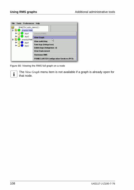
Using RMS graphs Additional administrative tools
Figure 80: Viewing the RMS full graph on a node
I The View Graph menu item is not available if a graph is already open for that node.
108 U42117-J-Z100-7-76

Additional administrative tools Using RMS graphs
By default, each graph appears as a separate tab in the right pane of the Cluster Admin view (Figure 81).
Figure 81: RMS full graph on a node—tab view
Ê To view any tab in a separate window, click the detach control button. The detach button is located next to the close control button in the upper-right corner of the view (Figure 82).
Figure 82: Detail of tab view showing detach button
The detached view contains the same information as the tabbed view (Figure 83).
U42117-J-Z100-7-76 109

Using RMS graphs Additional administrative tools
Figure 83: RMS full graph on a node—separate window view
Ê To rejoin the detached window to the Cluster Admin view, click the attach control button. The attach button is located next to the view’s close control button in the upper-right corner, just below the standard window control buttons (Figure 84).
Figure 84: Detail of separate window view showing attach button
The RMS full graph displays the complete RMS configuration of the cluster and represents the following items:
● Node where each application is currently online, indicated by green lines between the node and application objects
● Object types, indicated by the object’s icon
● Current object state, indicated by the colored bar beneath each icon
● Relationships between objects
● Dependencies of objects
110 U42117-J-Z100-7-76
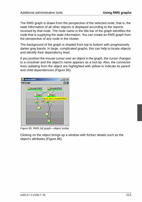
Additional administrative tools Using RMS graphs
The RMS graph is drawn from the perspective of the selected node; that is, the state information of all other objects is displayed according to the reports received by that node. The node name in the title bar of the graph identifies the node that is supplying the state information. You can create an RMS graph from the perspective of any node in the cluster.
The background of the graph is shaded from top to bottom with progressively darker gray bands. In large, complicated graphs, this can help to locate objects and identify their dependency level.
If you position the mouse cursor over an object in the graph, the cursor changes to a crosshair and the object’s name appears as a tool tip. Also, the connector lines radiating from the object are highlighted with yellow to indicate its parent and child dependencies (Figure 85).
Figure 85: RMS full graph—object tooltip
Clicking on the object brings up a window with further details such as the object’s attributes (Figure 86).
U42117-J-Z100-7-76 111

Using RMS graphs Additional administrative tools
Figure 86: RMS full graph—object details
6.2.2 Application graph
Ê To display the graph for a single application, right-click on the application object and select View Application Graph from the context menu (Figure 87).
Figure 87: Viewing an RMS application graph
112 U42117-J-Z100-7-76

Additional administrative tools Using RMS graphs
The application graph shares the same features as the full graph, except that it shows only the selected application and its resources (Figure 88). Like the full graph, the application graph is shown from the perspective of the selected node, and tooltips and details are available for every object.
Figure 88: Typical RMS application graph
6.2.3 Subapplication graph
Ê To display a subapplication graph, right-click on the parent application and select View Subapplication Graph from the context menu (Figure 89).
U42117-J-Z100-7-76 113

Using RMS graphs Additional administrative tools
Figure 89: Viewing an RMS subapplication graph
This graph displays all the subapplications used by the selected application, showing the connections between the subapplications (Figure 90).
Figure 90: Typical RMS subapplication graph
For clarity, names of the subapplication objects are shown as labels rather than tooltips, and various abstractions such as non-affiliated objects are not included. Like other graphs, clicking on an object brings up a window that displays its attributes.
114 U42117-J-Z100-7-76

Additional administrative tools Using RMS graphs
6.2.4 Composite subapplication graph
I The composite subapplication graph is available only for applications with controller objects.
When the configuration includes a controller object, the full graph of the node (or of either application) shows the parent and child applications in separate branches (Figure 91).
Figure 91: Standard view of configuration with controlled application
In some cases, it is convenient to view the child application as a resource of the parent so they both appear in the same branch. This is called a composite subapplication graph.
Ê To view a composite subapplication graph, right-click on the parent appli-cation and select View Composite Subapplication Graph from the context menu (Figure 92).
U42117-J-Z100-7-76 115

Using RMS graphs Additional administrative tools
Figure 92: Viewing an RMS composite subapplication graph
For every controller object in the subapplication graph, the graph of its controlled application is inserted with a dotted line connection to the parent controller. For example, note where App2 appears in the composite subapplication graph in Figure 93 below, and compare this to the standard graph shown earlier in Figure 91.
Figure 93: Typical composite subapplication graph
116 U42117-J-Z100-7-76

Additional administrative tools Using RMS graphs
If the controlled application has its own controller objects, then the process is recursively repeated. This gives a composite view of all the subapplications that the selected parent application depends on, whether directly or indirectly.
6.2.5 Using pop-up context menus from the graph
Each object in the RMS graph has a pop-up context menu that provides quick access to commonly-used operations.
Ê To display a context menu, right-click on any object in a graph.
The first item on the menu displays the selected object’s name in grayed-out text. The remaining items list the available operations, which vary according to the object’s type and current state (Figure 94).
Figure 94: Using a pop-up context menu from the RMS graph
Items that affect object states, node states, or the entire RMS configuration appear toward the bottom of the menu. These actions are described in the final sections of this chapter.
Ê To close the context menu without performing an operation, click the grayed-out object name in the menu or press the [Esc] key.
U42117-J-Z100-7-76 117

Using RMS graphs Additional administrative tools
6.2.6 Changing the displayed detail level
By default, the RMS graph does not display the resource (object) names on the graphs. These are available as tool tips and can be seen by placing the mouse over a particular object.
Ê To add any combination of resource names, affiliation names, “NoDisplay” nodes to the graphs, use the checkboxes on the Preferences menu.
Figure 95 shows the preference setting and a corresponding graph that displays resource names.
Figure 95: Displaying an RMS graph with affiliation names
118 U42117-J-Z100-7-76

Additional administrative tools Using RMS graphs
Figure 96 shows the preference setting and a corresponding graph that displays affiliation names.
Figure 96: RMS graph with resource names
U42117-J-Z100-7-76 119
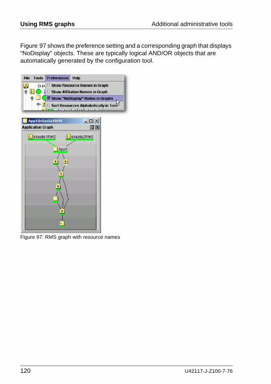
Using RMS graphs Additional administrative tools
Figure 97 shows the preference setting and a corresponding graph that displays “NoDisplay” objects. These are typically logical AND/OR objects that are automatically generated by the configuration tool.
Figure 97: RMS graph with resource names
120 U42117-J-Z100-7-76

Additional administrative tools Using RMS graphs
If two or more display options are selected, some of the object and resource names will consume more on-screen space (Figure 98). Horizontal scrollbars will appear when the graph is larger than the width of the screen, but the graph may still be difficult to read.
Figure 98: RMS graph with resource and affiliation names
In a complicated graph, it may help to sort the resource names alphabetically (Figure 99).
Figure 99: Sorting object names in the graph
U42117-J-Z100-7-76 121

Interpreting display changes Additional administrative tools
6.3 Interpreting display changes
The Cluster Admin view, the graphs, and the clusterwide table all have methods to denote the state of individual nodes as well as the overall configuration.
6.3.1 Display during RMS configuration changes
When you stop and restart RMS with a different configuration, the RMS tree, the clusterwide table, and the node graphs are redrawn in the same windows.
Figure 100 illustrates a Cluster Admin view overlaid by two individual node graphs and the clusterwide table, all displaying the state of a running configu-ration that monitors App1 and App2.
Figure 100: Cluster state before RMS is shut down
Figure 101 shows the same windows after RMS has been restarted, this time with a different configuration that monitors AppA and AppB.
122 U42117-J-Z100-7-76

Additional administrative tools Interpreting display changes
Figure 101: Cluster state after RMS restart with different configuration
The graphs and clusterwide table display the status of the same SysNode objects (shasta1 and shasta2) before and after the restart, so the windows remain open.
6.3.2 Display after RMS shutdown
After RMS is shut down, the background of RMS graph windows become dark gray on the node from which they are getting their information. In this condition, all the states are white, indicating that the states are unknown. The main view and the clusterwide table will continue to show the active application states until RMS is shut down on all nodes.
For example, suppose RMS is shut down only on one node (shasta1) of our example cluster. The graph on that node and the corresponding column of the clusterwide table will be shaded with a dark gray background (Figure 102).
U42117-J-Z100-7-76 123

Interpreting display changes Additional administrative tools
Figure 102: RMS main view, graphs, and clusterwide table after shutdown on one node
However, as long as RMS continues to run on the remaining node, shasta2, the RMS main view, the shasta2RMS graph, and the shasta2 column in the clusterwide table will indicate the online objects.
Application and subapplication graphs
When a node shuts down, any application or subapplication graph on that node would also change to the shutdown state (Figure 103).
Figure 103: Application graph on shutdown node
124 U42117-J-Z100-7-76
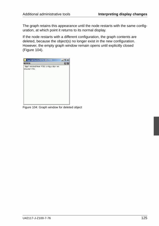
Additional administrative tools Interpreting display changes
The graph retains this appearance until the node restarts with the same config-uration, at which point it returns to its normal display.
If the node restarts with a different configuration, the graph contents are deleted, because the object(s) no longer exist in the new configuration. However, the empty graph window remain opens until explicitly closed (Figure 104).
Figure 104: Graph window for deleted object
U42117-J-Z100-7-76 125

Viewing RMS log messages Additional administrative tools
6.4 Viewing RMS log messages
The Cluster Admin interface provides a log viewer that lets you view and filter entries in the RMS switchlog and individual application logs on any node.
I All RMS log files, which normally reside in /var/opt/SMAWRrms/log/, can be viewed directly using a standard UNIX editor like vi.
I For meanings of error messages and possible corrective actions, refer to the RMS Reference Guide.
View the switchlog for a system node as follows:
Ê Right-click on the system node and select View Switchlog from the pop-up context menu (Figure 105). Alternatively, select a node and use Tools –> View switchlog (Figure 106).
Figure 105: Viewing the RMS switchlog file using a context menu
Figure 106: Viewing the RMS switchlog file using the Tools menu
126 U42117-J-Z100-7-76

Additional administrative tools Viewing RMS log messages
View an application log as follows:
Ê Right-click on an application on the RMS tree and choose View logfile from the pop-up context menu (Figure 107).
Figure 107: Viewing an application log using a context menu
I You can invoke equivalent context menus for an object from the Cluster Admin view, from the clusterwide table, or from any RMS graph containing that object.
U42117-J-Z100-7-76 127

Viewing RMS log messages Additional administrative tools
By default, each log file is displayed in a separate tab in the right pane (Figure 108).
Figure 108: RMS switchlog in tab view
Ê To view any tab in a separate window, click the detach control button. The detach button is located between the help and close control buttons in the upper-right corner of the view (Figure 109).
Figure 109: Detail of tab view showing detach button
128 U42117-J-Z100-7-76

Additional administrative tools Viewing RMS log messages
The detached view contains the same information as the tabbed view (Figure 110).
Figure 110: RMS switchlog in detached view
Ê To rejoin the detached window to the Cluster Admin view, click the attach control button. The attach button is located between the view’s help and close control buttons in the upper-right corner, just below the standard window control buttons (Figure 111).
Figure 111: Detail of detached window view showing attach button
I While in detached mode, the view’s close button and the standard window close button serve the same purpose: they both close the detached window.
In attached mode, the tabbed view’s close button closes only the visible tab. All other tabs remain open.
U42117-J-Z100-7-76 129

Viewing RMS log messages Additional administrative tools
6.4.1 Common procedures for switchlog and application log
By default, the entire log is available in the scrolled area at the bottom of the window. You can restrict the entries displayed with the following filters, which are described in subsections below:
● Time Filter—defines the time period of interest.
● Keyword Filter—selects a particular resource name (for an application only), error message severity level, non-zero exit code, or keyword.
I Refer to the RMS Reference Guide for a complete description of severity levels and exit codes.
Ê After you enter your filter criteria, click the Filter button to display the filtered log entries.
I All the selected and non-blank Time Filter and Keyword Filter controls are combined with a logical AND operation.
At any time, you can sort the displayed switchlog entries according to increasing or decreasing time by checking or unchecking the Reverse Order checkbox in the log viewer window.
130 U42117-J-Z100-7-76

Additional administrative tools Viewing RMS log messages
6.4.2 Time filter
The controls in the Time Filter panel allow you to limit the entries displayed in the log pane according to their date and time (Figure 112).
Figure 112: Search based on date and time range
Ê Select the Start Time and End Time using the scrolling input boxes (you can also type in the values directly) and then check the Enable checkbox.
The controls take effect the next time you click the Filter button.
Ê To remove the time filter, uncheck Enable and then click Filter.
U42117-J-Z100-7-76 131

Viewing RMS log messages Additional administrative tools
6.4.3 Keyword filters
The following items are available in the Keyword Filter panel.
6.4.3.1 Resource Name
I The Resource Name control is available only for application logs.
Ê Select a resource name from the dropdown list (Figure 113) and then click Filter.
Figure 113: Search based on resource name
Ê To remove the resource name filter, select No Selection from the dropdown list and then click Filter.
132 U42117-J-Z100-7-76

Additional administrative tools Viewing RMS log messages
6.4.3.2 Severity
Ê Select an message severity level from the dropdown list (Figure 114) and then click Filter.
Figure 114: Search based on severity level
Table 3 summarizes the RMS message log viewer severity levels.
Severity level Description
Emergency Systems cannot be used
Alert Immediate action is necessary
Critical Critical condition (fatal error)
Error Error condition (non-fatal error)
Warning Warning condition
Notice Normal but important condition
Info Miscellaneous information
Debug Debug messages
Table 3: RMS severity level description
U42117-J-Z100-7-76 133

Viewing RMS log messages Additional administrative tools
Ê To remove the severity level filter, select No Selection from the dropdown list and then click Filter.
6.4.3.3 Non-zero exit code
Ê Enter a numeric exit code in the Non-zero exit code input box and then click Filter.
6.4.3.4 Keyword
Ê Enter a string in the Keyword box (Figure 115) and then click Filter.
Figure 115: Search based on keyword
I Special characters and spaces are valid, but wildcards are not inter-preted. This search is not case-sensitive.
Ê To remove the keyword filter, clear the text in the Keyword box and then click Filter.
134 U42117-J-Z100-7-76

Additional administrative tools Viewing RMS log messages
6.4.4 Text search
You can search the text in the application log by right-clicking on the displayed text. A pop-up dialog with a Find entry allows you to perform a case-sensitive search in the direction you specify (Figure 116).
Figure 116: Using the pop-up Find dialog in log viewer
I The Find search string is processed literally You can include spaces and special characters, but wildcards are not interpreted.
6.4.5 Removing filters
To remove all filters, take the following steps:
● Uncheck the time filter Enable box.
● Set drop-down lists to No Selection
● Clear text from input boxes
● Click the Filter button
The unfiltered view will be restored.
U42117-J-Z100-7-76 135

Viewing RMS log messages Additional administrative tools
136 U42117-J-Z100-7-76

7 Controlling RMS operationChapter contents:
● “Managing RMS nodes” on page 137
● “Managing RMS applications” on page 149
● “Using maintenance mode” on page 160
7.1 Managing RMS nodes
This section describes basic procedures to control the operation of RMS, including how to start and stop individual nodes or the entire cluster. Procedures in this section are active: they change the state of the RMS cluster and may have a direct effect on the disposition of data.
As stated in the overview of this chapter, the primary means of administration is through the Cluster Admin GUI. This method should be used whenever possible. However, each procedure in this section includes a CLI alternative.
7.1.1 Starting RMS
When you use the GUI, you can only start the most recently activated configu-ration. To start a different configuration, you must first use the Wizard Tools to activate that configuration.
By default, the GUI will start RMS on all the nodes in the cluster. Alternatively, you can start RMS only on a single node that you select.
Ê From the Cluster Admin rms&pcs (or rms) tab, select Tools –> Start RMS (Figure 117).
Figure 117: Starting RMS from the main menu
U42117-J-Z100-7-76 137

Managing RMS nodes Controlling RMS operation
The RMS Start Menu window opens.
Ê To start RMS on all nodes, click the all available nodes radio button and then click OK (Figure 118).
Figure 118: RMS Start Menu for all nodes
Ê To start RMS only on a single node, click the one node from the list radio button, and then choose the node using a checkbox in the Selection column. After making your selections, click OK (Figure 119).
138 U42117-J-Z100-7-76

Controlling RMS operation Managing RMS nodes
Figure 119: RMS Start Menu for individual nodes
Alternatively, you can start RMS on individual nodes directly from the Cluster Admin window:
1. In the left pane, click the rms&pcs tab to view the cluster tree.
2. Right-click on the node and select Start RMS from the pop-up menu (Figure 120).
Figure 120: Starting RMS on individual nodes
U42117-J-Z100-7-76 139

Managing RMS nodes Controlling RMS operation
CLI: hvcm
The hvcm command starts the base monitor and the detectors for all monitored resources. The CLI syntax for hvcm has two possible formats:
Format 1hvcm [-a | -s SysNode]
Format 2hvcm -c config_name [-a | -s SysNode] [-h timeout] [-l loglevels]
The options valid for both formats are:-a Start RMS on all nodes in the configuration-s Start RMS only on the specified node
If neither ‘-a’ nor ‘-s’ is specified, hvcm starts RMS only on the local node.
The options valid only for Format 2 are:-c Use the specified configuration file-h Use the specified heartbeat recovery timeout-l Activate diagnostic output according to the specified level(s)
I To start a configuration other than the one most recently activated, change the heartbeat recovery timeout, or set the diagnostic level, you must use the CLI. These parameters cannot be adjusted from the Cluster Admin GUI.
Notes for Format 1
When the ‘-c’ option is not present, hvcm reads the default CONFIG.rms startup file. hvcm looks for the default startup file in <RELIANT_PATH>/etc/CONFIG.rms. If the default for the environment variable RELIANT_PATH has not been changed, this resolves to /opt/SMAW/SMAWRrms/etc/CONFIG.rms. Note that the search is always confined to the local node, even if you specify the ‘-a’ or ‘-s’ option to start RMS remotely.
The CONFIG.rms file contains either of the following:
● A simple configuration name, optionally with a ‘.us’ suffix.
● An hvcm command compliant with Format 2 that starts the most recently activated configuration.
You cannot specify the ‘-h’ or ‘-l’ options in Format 1. You can, however, edit the CONFIG.rms file and insert the options to comply with Format 2.
140 U42117-J-Z100-7-76

Controlling RMS operation Managing RMS nodes
Notes for Format 2
When the ‘-c’ option is present, and the configuration file is not an absolute path, hvcm looks for the first match in <RELIANT_STARTUP_PATH>. If the default for the environment variable RELIANT_STARTUP_PATH has not been changed, this resolves to /opt/SMAW/SMAWRrms/build/<config_name>.us (hvcm adds the ‘.us’ extension if it is not specified as part of the configuration file name). If an absolute path is specified, hvcm attempts to read only that file. Note that the search is always confined to the local node, even if you specify the ‘-a’ or ‘-s’ option to start RMS remotely.
When hvcm locates the specified configuration file, it checks to see if the default CONFIG.rms file is also present. If it is, hvcm compares the configuration names defined by both files to make sure they agree. If they do not agree, hvcm aborts the startup processing.
The ‘-h’ option sets the UDP heartbeat recovery timeout for the cluster. See “Nodes and heartbeats” on page 11. The default timeout depends on which method RMS uses to monitor the cluster:
● By default, RMS monitors the state of each node with the Enhanced Lock Manager (ELM), which is implemented in the Cluster Foundation. ELM is not a polling method. Instead, it relies on locks that are held by each node and released when the node or its base monitor go down. When ELM is enabled, the UDP heartbeat timeout defaults to 600 seconds.
● ELM can be disabled for rolling upgrade or debugging operations by setting the HV_USE_ELM environment variable to zero (0). See “HV_USE_ELM” on page 211. When ELM is disabled, the UDP heartbeat defaults to 45 seconds.
I Specifying a heartbeat timeout shorter than the default may cause premature node kills. No data loss will occur, because a node kill begins with a graceful shutdown. However, cluster performance may suffer due to latency as applications are switched to different nodes. Excessively short heartbeat timeouts may also interfere with CF event timeouts.
The ‘-l’ option sets the diagnostic output level at startup time. The loglevels specification consists of one or more individual numeric levels or hyphen-delimited ranges, each separated by a comma. For more information about this expert-level feature, see the RMS Reference Guide
U42117-J-Z100-7-76 141

Managing RMS nodes Controlling RMS operation
7.1.2 Starting RMS automatically at boot time
I This setting takes effect at the next system startup
You can use the following procedure to activate or deactivate automatic RMS startup when the system boots up.
Ê From the Cluster Admin rms&pcs (or rms) tabbed view, select Tools > Auto Start RMS on Node Boot (Figure 121).
Figure 121: Controlling automatic RMS startup—step 1
You can then choose to activate (or deactivate) the automatic RMS startup on all nodes, or on just one node (Figure 122).
142 U42117-J-Z100-7-76

Controlling RMS operation Managing RMS nodes
Figure 122: Controlling automatic RMS startup—step 2
CLI: hvsetenv
At system startup, the RMS rc script checks the environment variable settings: if the HV_RCSTART environment variable is set to 1, the rc script will attempt to start RMS using the CONFIG.rms file. You can set the HV_RCSTART variable with the hvsetenv command as follows:
hvsetenv HV_RCSTART [0|1]
The allowable values are:0 Do not start RMS at boot time1 Start RMS at boot time (default)
If no value is specified, the command reports the current value of the HV_RCSTART environment variable.
7.1.3 Stopping RMS
You can stop RMS on all nodes or on a subset that you select.
Use the Tools pull-down menu (Figure 123) and select Shutdown RMS.
U42117-J-Z100-7-76 143

Managing RMS nodes Controlling RMS operation
Figure 123: Using the Tools menu to stop RMS
Ê To stop RMS on all nodes, click the radio button for all available nodes and then click Ok (Figure 124).
Figure 124: Stopping RMS on all available nodes
When you shut down all available nodes, two radio buttons allow you to choose how you want to handle the applications:
● Stop all Apps—Stops all user applications
● Keep local Apps—Leaves the applications running
144 U42117-J-Z100-7-76

Controlling RMS operation Managing RMS nodes
V Caution
Leaving the applications running after stopping RMS can lead to data inconsistencies or corruption.
To stop RMS on one specific node, select the radio button for one node from the list, and then click the checkbox of the node you want to shut down (Figure 125).
Figure 125: Stopping RMS on one node from the list
Each node has a dropdown list in the Options column to provide additional control:
● Stop all Apps—Stops all user applications on the selected node
● Keep local Apps—Leaves the applications running on the selected node
● Forced shutdown—Performs a forced shutdown of RMS
V Caution
Leaving the applications running after stopping RMS or using a forced shutdown can cause data inconsistencies or corruption.
Ê Click the Ok button to initiate the shutdown with your selections.
U42117-J-Z100-7-76 145

Managing RMS nodes Controlling RMS operation
Stop all Apps is the default option for shutting down RMS on all nodes or on one node. If you select an option other than the default, you will be prompted to confirm the operation (Figure 126 and Figure 127).
Figure 126: Stopping RMS while keeping applications—confirmation
Figure 127: Forced shutdown of RMS—confirmation
You can also stop RMS on a single node by right-clicking on the node in the RMS tree and then selecting Shutdown RMS from the context menu (Figure 128).
Figure 128: Using the context menu to stop RMS on one node
146 U42117-J-Z100-7-76

Controlling RMS operation Managing RMS nodes
Only one node will appear in the confirmation window (Figure 129).
Figure 129: Stopping RMS on one node
CLI: hvshut
The syntax for the CLI is as follows:
hvshut {-a | -A | -f | -l | -L | -s SysNode}
Options:-a Shut down RMS and applications on all nodes-A Shut down RMS on all nodes without shutting down applications-f Forced (emergency) shutdown of RMS on the local node-l Shut down RMS and applications on the local node-L Shut down RMS on the local node without shutting down applications-s Shut down RMS only on the specified node
The hvshut command shuts down the RMS software on one or more nodes in the configuration. The base monitor on the local node sends a message to other online nodes indicating which node or nodes are to be shut down. The hvshut command disables all error detection and recovery routines on the nodes being shut down, but does not shut down the operating system.
U42117-J-Z100-7-76 147

Managing RMS nodes Controlling RMS operation
If any userApplication objects are online when the -A, -f, or -L options are used, the applications remain running but are no longer monitored by RMS. Both The -f and -L options affect only the local node, but the -f option is for emergencies (when other hvshut options do not work).
When you choose to shut down RMS without shutting down the monitored appli-cations, you will be prompted to confirm the operation.
V Caution
Use the hvshut -A, -f, and -L options carefully as they could result in inconsistencies or data corruption.
7.1.4 Clearing a SysNode Wait state
A node is put in the Wait state when the Shutdown Facility (SF) attempted to kill the node but could not successfully complete the shutdown within the timeout period. When you manually clear a wait state, RMS marks the specified node as being in either the online or offline state according to your selection, regardless of its state before the entering the wait state.
V Caution
When you clear a wait state, be sure that the target state corresponds to the actual, physical state of the node. RMS, CF, and SF mark the node as being in the confirmed state you select. If the node is not truly in that state, conflicts and data corruption may occur.
If the Shutdown Facility (SF) timeout for a node has not yet been exceeded, requests to clear a wait state for that node will be ignored.
Clear any node in the Wait state as follows:
Ê Right-click on the node and select the Online or Offline option from the context menu.
CLI: hvutil -o and hvutil -u
Use the hvutil command to clear a wait state. To put the node in the online state, use the -o option:
hvutil -o SysNode
To put the node in the offline state, use the -u option:
hvutil -u SysNode
148 U42117-J-Z100-7-76

Controlling RMS operation Managing RMS applications
7.2 Managing RMS applications
This section describes basic procedures related to starting, stopping, and clearing special states of individual applications. Procedures in this section are active: they change the state of the RMS cluster and may have a direct effect on the disposition of data.
As stated in the overview of this chapter, the primary means of administration is through the Cluster Admin GUI. This method should be used whenever possible. However, each procedure in this section includes a CLI alternative.
7.2.1 Overriding automatic application startup
By default, the automatic startup of each application is controlled by its AutoStartUp attribute, which is typically set in the Wizard Tools configuration interface:
● If AutoStartUp is set to 1, the application starts automatically when RMS starts or when the application is switched to another node.
● If AutoStartUp is set to 0, the application must be started manually as described in “Starting RMS” on page 137.
Automatic application startup can cause problems during some maintenance or troubleshooting procedures. If this is the case, you can suppress the AutoStartUp attribute for all applications.
I The following procedure changes the HV_AUTOSTARTUP global environment variable. Changes to HV_AUTOSTARTUP do not take effect until the next RMS startup.
Ê From the Cluster Admin rms&pcs (or rms) tab, select Tools –> UserApplications AutoStartup (Figure 130).
Figure 130: Controlling automatic application startup—step 1
U42117-J-Z100-7-76 149
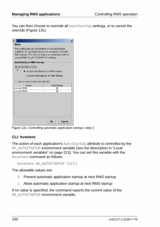
Managing RMS applications Controlling RMS operation
You can then choose to override all AutoStartUp settings, or to cancel the override (Figure 131).
Figure 131: Controlling automatic application startup—step 2
CLI: hvsetenv
The action of each application’s AutoStartUp attribute is controlled by the HV_AUTOSTARTUP environment variable (see the description in “Local environment variables” on page 213). You can set this variable with the hvsetenv command as follows:
hvsetenv HV_AUTOSTARTUP [0|1]
The allowable values are:
0 Prevent automatic application startup at next RMS startup
1 Allow automatic application startup at next RMS startup
If no value is specified, the command reports the current value of the HV_AUTOSTARTUP environment variable.
150 U42117-J-Z100-7-76
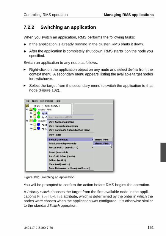
Controlling RMS operation Managing RMS applications
7.2.2 Switching an application
When you switch an application, RMS performs the following tasks:
● If the application is already running in the cluster, RMS shuts it down.
● After the application is completely shut down, RMS starts it on the node you specified.
Switch an application to any node as follows:
Ê Right-click on the application object on any node and select Switch from the context menu. A secondary menu appears, listing the available target nodes for switchover.
Ê Select the target from the secondary menu to switch the application to that node (Figure 132).
Figure 132: Switching an application
You will be prompted to confirm the action before RMS begins the operation.
A Priority switch chooses the target from the first available node in the appli-cation’s PriorityList attribute, which is determined by the order in which the nodes were chosen when the application was configured. It is otherwise similar to the standard Switch operation.
U42117-J-Z100-7-76 151

Managing RMS applications Controlling RMS operation
By default, RMS attempts a normal shutdown. If this fails, RMS does not proceed with the startup phase because two competing instances of the same application could cause data corruption. In this event, you can use the Forced switch operation.
V Caution
Use the Forced switch mode only if an application cannot be switched normally. A forced application switch overrides all safety checks and could therefore result in data corruption or other inconsistencies.
If the application is busy, the pop-up context menu will not offer the choices to switch the application. Instead, the menu will offer view-only operations, and the last menu item will indicate that the application is in a Wait state (Figure 133).
Figure 133: Switching a busy application
CLI: hvswitch
The syntax for the CLI is as follows:
hvswitch [-f] userApplication [SysNode]
The hvswitch command manually switches control of a userApplication resource from one system node to another in the RMS configuration. The resource being switched must be of type userApplication. The system node must be of type SysNode. If no SysNode is specified, the application is switched to the local node. The -f option is a forced-switch option.
V Caution
Use the ‘hvswitch -f’ operation carefully. A forced application switch overrides all safety checks and could therefore result in data corruption or other inconsistencies.
152 U42117-J-Z100-7-76

Controlling RMS operation Managing RMS applications
7.2.3 Starting an application
If the application is already offline everywhere in the cluster, you can start it (bring it online) on a single node as follows:
Ê Right-click on the application object and select Online from the pop-up context menu (Figure 134).
Figure 134: Starting an application
You will be prompted to confirm the action before RMS begins the operation.
CLI: hvswitch
Starting an application on the local node, like switching an application to another node, employs the hvswitch command. Refer to “CLI: hvswitch” on page 152 for the syntax.
U42117-J-Z100-7-76 153

Managing RMS applications Controlling RMS operation
7.2.4 Stopping an application
Stop an online application (take it offline) as follows:
Ê Right-click on the online application object and select Offline from the pop-up context menu (Figure 135).
Figure 135: Shutting down an application
You will be prompted to confirm the action before RMS begins the operation.
CLI: hvutil -f
The syntax for the CLI is as follows:
hvutil -f userApplication
Note that this is a normal offline request. There is no “forced” offline request for a userApplication.
I Use the command ‘hvutil -s userApplication’ to bring an offline userApplication to a Standby state.
154 U42117-J-Z100-7-76
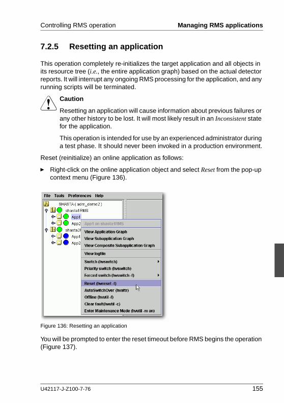
Controlling RMS operation Managing RMS applications
7.2.5 Resetting an application
This operation completely re-initializes the target application and all objects in its resource tree (i.e., the entire application graph) based on the actual detector reports. It will interrupt any ongoing RMS processing for the application, and any running scripts will be terminated.
V Caution
Resetting an application will cause information about previous failures or any other history to be lost. It will most likely result in an Inconsistent state for the application.
This operation is intended for use by an experienced administrator during a test phase. It should never been invoked in a production environment.
Reset (reinitialize) an online application as follows:
Ê Right-click on the online application object and select Reset from the pop-up context menu (Figure 136).
Figure 136: Resetting an application
You will be prompted to enter the reset timeout before RMS begins the operation (Figure 137).
U42117-J-Z100-7-76 155

Managing RMS applications Controlling RMS operation
Figure 137: Choosing the reset timeout for the application
If RMS fails to re-initialize the entire application graph during this amount of time, it terminates with an error message. Default: 10 seconds
Ê Adjust the timeout value if desired, and then click Yes to reset the application.
CLI: hvreset -t
The syntax for the CLI is as follows:
hvreset -t timeout userApplication
hvreset displays a message that warns of the consequences and then prompts you to confirm the action before proceeding.
When the userApplication is not performing online, offline, or fault processing, hvreset returns immediately and displays a message stating there is nothing to do. This case is considered to be successful command execution and returns exit code 0.
156 U42117-J-Z100-7-76

Controlling RMS operation Managing RMS applications
7.2.6 Changing AutoSwitchOver setting for an application
An application’s AutoSwitchOver attribute specifies whether or not it should be automatically switched to another node in the event of a resource failure, a node failure, or a node shutdown. This attribute is set for each application at configu-ration time, but you can change it at runtime with the following procedure:
Ê Right-click on the application object on any node and select AutoSwitchOver in the context menu (Figure 138).
Figure 138: Changing an application’s AutoSwitchOver settings—step 1
Ê Select the desired settings from the secondary pop-up window (Figure 139).
U42117-J-Z100-7-76 157

Managing RMS applications Controlling RMS operation
Figure 139: Changing an application’s AutoSwitchOver settings—step 2
If you choose Automatic recovery, you can select or deselect one or more of the indicated conditions by clicking the appropriate checkboxes.
Ê Click Ok to confirm the AutoSwitchOver change on all nodes.
As soon as you click Ok, RMS starts updating the application’s AutoSwitchOver setting throughout the cluster. The operation typically requires only a few seconds to update each node, but it may take longer in some unusual cases. There is no notification at either the beginning or the end of the process.
If some nodes are unreachable, RMS does not issue a warning. Instead, if one of the unreachable nodes becomes available at a later time, RMS automatically updates the application’s AutoSwitchOver setting on that node as soon as the base monitor starts up. This guarantees that the AutoSwitchOver setting is consistent on every running node in the application’s priority list.
CLI: hvattr
The syntax for the CLI is as follows:
hvattr <userApplication>:AutoSwitchOver:<value> ...
The hvattr command is designed as a general-purpose command to perform clusterwide modifications of attributes at the application level. Each argument on the command line specifies a colon-separated triad of the application name, the attribute to modify, and the new value to be applied. You can supply multiple arguments on one command line, where each argument specifies a unique combination of application and attribute names.
158 U42117-J-Z100-7-76

Controlling RMS operation Managing RMS applications
Currently, only the AutoSwitchOver attribute is available to the user. For its allowable values, see “AutoSwitchOver” on page 196.
I When specifying an attribute value that contains the pipe character, the attribute value must be surrounded in quotes to prevent the shell from interpreting the pipe character itself.
You should avoid issuing multiple hvattr commands simultaneously. Normally, concurrent calls to hvattr will be gracefully rejected. In rare circumstances, hvattr may not complete until timeout occurs, in which case you must wait until the running command exits before issuing another hvattr command.
7.2.7 Clearing a fault
For an application that is in the Faulted state, clear the fault as follows:
Ê Right-click on the application object and select Clear Fault from the pop-up context menu (Figure 140).
Figure 140: Clearing an application fault
Before the command proceeds, you will be informed of the action to be taken and prompted to confirm the operation (Figure 141).
Figure 141: Clearing an application fault—confirmation dialog
See also “Clearing faults in maintenance mode” on page 165.
U42117-J-Z100-7-76 159

Using maintenance mode Controlling RMS operation
CLI: hvutil -c
The syntax for the CLI is as follows:
hvutil -c userApplication
I If the userApplication is in the online state, then clearing the fault will cause RMS to attempt to bring the faulted resource to the online state. If the userApplication is in the offline or faulted state, then clearing the fault will attempt to bring the resource to the offline state. You will be informed of the action that is to be taken and prompted to confirm the operation before the command proceeds.
7.2.8 Activating an application
Activating an application takes it from the Deact state to the Offline state. It does not bring it Online. Also, activating a userApplication with the Cluster Admin GUI or the CLI has nothing to do with activating an RMS configuration in the Wizard Tools—the two operations are completely independent. Activate a deactivated application as follows:
Ê Right-click on the application object and select the Activate option from the pop-up menu.
CLI: hvutil -a
The syntax for the CLI is as follows:
hvutil -a userApplication
I You will not need to activate an application unless someone explicitly deactivated it with the command ‘hvutil -d userApplication’.
7.3 Using maintenance mode
Maintenance mode is a special mode of operation that allows an application to be temporarily decoupled from its dependent resources. This allows, for example, a file system to be taken offline for backup purposes without disrupting the online state of its parent application.
160 U42117-J-Z100-7-76

Controlling RMS operation Using maintenance mode
7.3.1 Entering maintenance mode
You can enter maintenance mode for all applications on all nodes as follows:
Ê Right-click on the cluster at the top of the RMS tree and select Enter Mainte-nance Mode from the popup menu (Figure 142).
Figure 142: Starting maintenance mode for all applications
Enter maintenance mode for only one application as follows:
Ê Right-click on an application instance in the RMS tree and select Enter Maintenance Mode from the popup menu (Figure 143).
Figure 143: Starting maintenance mode for a single application
In either case, you will be prompted to confirm the operation (Figure 144 and Figure 145).
U42117-J-Z100-7-76 161

Using maintenance mode Controlling RMS operation
Figure 144: Maintenance mode confirmation for all applications
Figure 145: Maintenance mode confirmation for one application
I Maintenance mode is clusterwide: if an application is in maintenance mode on one node, it is also in maintenance mode on any other node where it can run.
Figure 146 shows the Cluster Admin window after one application is put into maintenance mode.
Figure 146: Typical cluster in maintenance mode
162 U42117-J-Z100-7-76

Controlling RMS operation Using maintenance mode
Note how the right half of the application status icons indicate the intended state (the state that would be attained if the application were taken out of mainte-nance mode). The intended state is also indicated by the application’s StateDetails attribute, which is the first item in the Attributes table in the right pane.
7.3.2 Maintenance mode operating notes
When an application enters maintenance mode (MM), it affects all other appli-cations that share the same graph. For example, if two applications are linked by a controller, then putting one in maintenance mode will cause the other to go into maintenance mode as well; which one is the parent and which one is the child does not matter in this case.
Conversely, if two applications do not share the same graph, i.e., they are not linked by one or more controllers, then one can be put into MM while the other operates under normal RMS control.
For instance, in the example presented earlier, App1 and App2 are independent. While App1 is in MM, App2 continues to operate normally and can be switched from one node to the other, as illustrated in Figure 147 below.
Figure 147: Normal operation of independent application
7.3.2.1 Overall cluster restrictions in maintenance mode
Even though some applications may continue to operate under normal RMS control, MM still places restrictions on the overall cluster operation. In particular, note the following:
● You must exit MM for an application before you can switch that application offline or to another node.
● You must exit MM everywhere in the cluster before you can shut down RMS.
U42117-J-Z100-7-76 163

Using maintenance mode Controlling RMS operation
7.3.3 Exiting maintenance mode
To exit maintenance mode, use the following procedure:
Ê Right-click on the cluster or an application and select Exit Maintenance Mode from the popup menu (Figure 148 and Figure 149).
Figure 148: Normal maintenance mode exit for all applications
Figure 149: Normal maintenance mode exit for a single application
In either case, you will be prompted to confirm your action before the operation proceeds.
I You can exit maintenance mode for a single application even if you entered maintenance mode for the entire cluster.
Note that both the cluster and application popup menus shown above contain a Force Exit Maintenance Mode item. If you choose this command, it will force RMS to exit maintenance mode even if some resources are not in the appropriate state. The prompt to confirm the operation for one application is shown in Figure 150; the prompt for all applications is similar.
164 U42117-J-Z100-7-76

Controlling RMS operation Using maintenance mode
Figure 150: Forced maintenance mode confirmation for all applications
7.3.4 Clearing faults in maintenance mode
If a fault occurs in an application while it is in maintenance mode, you must clear the fault before that application can return to normal operation. (It does not prevent other applications from returning to normal mode.)
RMS marks this type of fault condition with a blue exclamation mark next to the Maintenance-Online status icon, and with the state name Online!! in the clusterwide table (Figure 151).
Figure 151: Application with fault condition during maintenance mode
To clear the fault, right-click on the faulted object and choose Clear fault in either the configuration tree (Figure 152) or the clusterwide table (Figure 153).
U42117-J-Z100-7-76 165

Using maintenance mode Controlling RMS operation
Figure 152: Fault clearing from configuration tree
Figure 153: Fault clearing from clusterwide table
After the fault is cleared successfully, the application returns to normal mainte-nance mode (Figure 154).
Figure 154: Application returned to normal maintenance mode
In some cases, it may be necessary to select Force Exit Maintenance Mode from the context menu. If this is successful, the application will return to normal operation mode with the fault cleared.
166 U42117-J-Z100-7-76

Controlling RMS operation Using maintenance mode
7.3.5 Maintenance mode CLI: hvutil -m and -M
Control maintenance mode (MM) with the hvutil command:
hvutil -M { on | off | forceoff }
hvutil -m { on | off | forceoff } userApplication
The hvutil maintenance mode commands operate synchronously, so they do not return until the final state has been reached or until an error occurs. In the particular case where ‘-m off’ returns a failure because one or more resources were in an inappropriate state, an error message is displayed that lists the problem resources.
Options:
-M Applies the MM operation to all applications on all nodes
-m Applies the MM operation to the specified application on all nodes
Operations:
on Starts maintenance mode
off Stops MM if all resources are in the appropriate state
forceoff Forces MM to stop even if all resources are not in the appropriate state
U42117-J-Z100-7-76 167

Using maintenance mode Controlling RMS operation
168 U42117-J-Z100-7-76

U42117-J-Z100-7-76
Part III: Reference


8 Appendix—Site preparation
The PRIMECLUSTER Installation Guide for your operating system describes how to prepare your cluster to operate RMS. Some of the procedures require you to modify system files so that RMS can identify the hosts, file systems, and network interfaces used in a configuration. You should have completed these procedures when RMS was installed.
In some cases, you will be creating or modifying your RMS configuration because changes have been made to your site. Certain site changes may require you to review and update your system files first. These changes include, but are not limited to, the following:
● IP addresses were changed.
● Redundant interconnects were added to the cluster.
● Hosts were added, removed, or renamed.
● Two or more clusters were merged into one.
● File systems or SANs were added or removed.
For convenience, the site preparation descriptions for hosts, file systems, and networks are duplicated here. If any of these specifications have changed since your initial RMS installation, you should review this material and make the necessary adjustments before proceeding with your RMS configuration.
The modifications generally involve adding RMS-specific entries to standard system files; pre-existing entries required for proper operation of your hosts and network are not affected. Resources for market-specific applications may require similar customization.
8.1 Network database files
8.1.1 /etc/hosts
The /etc/hosts file must contain the IP addresses and RMS names of all the host systems that are part of the cluster.
RMS uses its own internal set of host names to manage the machines in the cluster. When you configure the cluster, you will use the RMS host names and not the standard host names. These names must be entered in /etc/hosts on
U42117-J-Z100-7-76 171
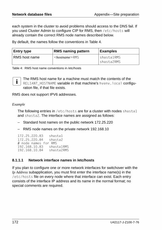
Network database files Appendix—Site preparation
each system in the cluster to avoid problems should access to the DNS fail. If you used Cluster Admin to configure CIP for RMS, then /etc/hosts will already contain the correct RMS node names described below.
By default, the names follow the conventions in Table 4.
I The RMS host name for a machine must match the contents of the RELIANT_HOSTNAME variable in that machine’s hvenv.local configu-ration file, if that file exists.
RMS does not support IPV6 addresses.
Example
The following entries in /etc/hosts are for a cluster with nodes shasta1 and shasta2. The interface names are assigned as follows:
– Standard host names on the public network 172.25.220
– RMS node names on the private network 192.168.10
172.25.220.83 shasta1172.25.220.84 shasta2# node names for RMS192.168.10.83 shasta1RMS192.168.10.84 shasta2RMS
8.1.1.1 Network interface names in /etc/hosts
If you plan to configure one or more network interfaces for switchover with the Ip Address subapplication, you must first enter the interface name(s) in the /etc/hosts file on every node where that interface can exist. Each entry consists of the interface IP address and its name in the normal format; no special comments are required.
Entry type RMS naming pattern Examples
RMS host name <hostname>RMS shasta1RMSshasta2RMS
Table 4: RMS host name conventions in /etc/hosts
172 U42117-J-Z100-7-76

Appendix—Site preparation Configuration resource definitions
Example
If the interface shastavip with IP address 172.25.222.223 can be switched between nodes shasta1 and shasta2, then both nodes should contain the following line in /etc/hosts:
172.25.222.223 shastavip
I When you configure the Ip Address subapplication, you specify the interface name as it appears in /etc/hosts, and not the IP address.
8.1.2 /root/.rhosts (Linux) and /.rhosts (Solaris)
Contains entries to control trusted login from remote hosts.
The Wizard Tools require automatic login or authentication as root on every machine in the cluster. One method is to include the names of trusted hosts in the .rhosts file, which must be modified appropriately on each node. See the rhosts manual page for a complete description of the format.
Example
If the cluster consists of hosts shasta1 and shasta2, then every machine’s .rhosts file should contain the following lines:
shasta1 rootshasta2 root
I The Cluster Foundation (CF) provides the equivalent of .rhosts functionality for all RMS configuration, administration, and operation tasks.
8.2 Configuration resource definitions
8.2.1 /opt/SMAW/SMAWRrms/etc/hvipalias
This file contains entries for all of the network interfaces that are to be used as resources in the configuration. Typically, each entry associates a logical interface name, or IP alias, with a physical interface on a specified node. The IP alias always presents the same IP address, even though it is switched from node to node, and even if the underlying physical interface has different charac-teristics on each node.
U42117-J-Z100-7-76 173

Configuration resource definitions Appendix—Site preparation
I Each IP alias with its IP address must be entered in the /etc/hosts file. The IP address does not appear in the hvipalias file.
Each entry in hvipalias must contain the following fields:
<Uname> <IfName> <IfDevice> <Netmask>
The fields are defined as follows:
● Uname—Name of the machine to host the logical interface. This is usually the value returned by the ‘uname -n’ command.
Alternatively, you can use the Cluster Foundation (CF) node name, which is returned by the ‘cftool -ql’ command. This can be used to differentiate two machines which are configured with the same ‘uname -n’ setting, provided they were assigned different names when CF was configured.
● IfName—Logical interface name, or IP alias. This name must appear with its associated IP address in the node’s /etc/hosts file, and the associated IP address must be the same on every node.
● IfDevice—Physical device name to be associated with the logical interface when it is switched to the specified machine.
If you specify two comma-separated device names, and the first device fails, the logical interface will failover to the second device.
● Netmask—The netmask to use with the IP address associated with the interface name, specified in the standard hexadecimal 8-digit format. The netmask is set with an ifconfig command after the physical device is brought online.
I To avoid network conflicts, a network hostname or address monitored by the IpAddress subapplication can be active on only one node in the cluster at any time.
When a configuration is activated, the local hvipalias file is copied to every other node in the configuration; the file with same name and path on the remote node will be overwritten with the new content. Therefore, the file must contain one line for every combination of interface and host where that interface can be switched.
For instance, if the interface named dbhost can be switched between two nodes, then hvipalias on each node should contain lines for both the local and remote interfaces:
174 U42117-J-Z100-7-76

Appendix—Site preparation Configuration resource definitions
Example (Linux)
#Uname IfName IfDevice Netmaskshasta1 dbhost eth1 0xffffff00shasta2 dbhost eth1 0xffffff00
Example (Solaris)
#Uname IfName IfDevice Netmaskfuji2 dbhost hme0 0xffffff00fuji3 dbhost hme0 0xffffff00
If you specify the interface as device1,device2 then the IP address will failover to the second device if the first device fails:
Example (Linux)
#Uname IfName IfDevice Netmaskshasta1 dbhost eth1,eth2 0xffffff00shasta2 dbhost eth1,eth2 0xffffff00
Example (Solaris)
#Uname IfName IfDevice Netmaskfuji2 dbhost hme0,hme1 0xffffff00fuji3 dbhost hme0,hme1 0xffffff00
8.2.1.1 Optional fields
The following fields are optional. If specified, they must appear after the required fields in the order presented here.
MAC address (Solaris only)
You can specify the MAC address of an interface to ensure that external connec-tions remain valid when the logical name is switched to another controller. Specify this field with the keyword MAC, followed immediately by the MAC address in the standard colon-delimited, 6-byte, hexadecimal format, e.g., MAC00:80:17:28:25:9c.
The leading MAC keyword indicates the address is to be validated before it is used. You may omit the leading MAC keyword to indicate the address does not have to be validated, but this is not recommended.
The MAC Address field must appear after the Netmask field.
U42117-J-Z100-7-76 175

Configuration resource definitions Appendix—Site preparation
I The MAC address feature requires the FJSVclmac and FSUNnet packages.
Example
#Uname IfName IfDevice Netmaskfuji2 dbhost hme0,hme1 0xffffff00 MAC00:80:17:28:25:9cfuji3 dbhost hme0,hme1 0xffffff00 00:80:17:28:25:9c
ifconfig parameters
You can specify a set of arguments to be sent to the ifconfig command. This allows you to specify custom interface settings that may be required for a physical device before the interface is switched there.
The field begins with the IFCONFIG keyword (all uppercase), followed by whitespace, followed by the comma-delimited argument string that will be passed to the ifconfig command. The keyword and arguments must appear after the Netmask field (or the MAC Address field, if present) and before any Route arguments.
For example, if an mtu value of 1200 is required for the local device associated with the dbhost alias, the entry for the local node would be as follows:
Example (Linux)
#Uname IfName IfDevice Netmaskshasta1 dbhost eth1,eth2 0xffffff00 IFCONFIG mtu,1200
Example (Solaris)
#Uname IfName IfDevice Netmaskfuji2 dbhost hme0,hme1 0xffffff00 IFCONFIG mtu,1200
After an interface is successfully brought online, the ifconfig command with the specified netmask and additional arguments will be invoked for the associated device.
Route parameters
Remaining fields at the end of the line are passed to a route command for the configured interface. If the string $INTF is encountered, it is replaced by the interface name; otherwise, the fields are passed literally.
176 U42117-J-Z100-7-76
Appendix—Site preparation Linux file systems
I Do not include the add or delete subcommands in the argument list. RMS generates these automatically when the interface is brought online or offline.
Example (Linux)
shasta1 dbhost eth1,eth2 0xffffff00 default dev $INTF
Example (Solaris)
fuji2 dbhost hme0,hme1 0xffffff00 default dev $INTF
When the dbhost interface is brought online, RMS will issue the following command:
route add default dev dbhost
8.2.2 /opt/SMAW/SMAWRrms/etc/hvconsoles
Controls customized handling of fault messages, usually to remote consoles or special devices such as pagers. This does not affect the standard messages written to the RMS or system log files.
Each entry specifies a program to be executed when an RMS resource object encounters a fault.
If the file does not exist, you will receive no customized fault information. A complete description of the format is available in the comments in the hvconsoles.template file.
8.3 Linux file systems
To manage Linux file systems with RMS, you must create entries in the /etc/fstab.pcl and /etc/exports.pcl configuration files as described in the following sections. These configuration files share the following features:
● Leading whitespace and empty lines are ignored.
● A line beginning with the string ‘#RMS#’ or ‘#RMS:<appname>#’ is a file system specification for RMS. The entire specification must be on the same line—continuation to additional lines is not allowed.
● Any other line beginning with a pound sign (#), or any line beginning with an asterisk (*), is treated as a comment.
U42117-J-Z100-7-76 177

Linux file systems Appendix—Site preparation
● All other lines are presently ignored. However, they may be processed by future versions of RMS.
8.3.1 /etc/fstab.pcl
This file contains entries for all of the local and remote file systems that are to be used as resources in the configuration. RMS is responsible for mounting and unmounting each of these file systems in order to bring them online or offline, respectively, according to the requirements of the running configuration.
For each file system to be managed by RMS, create a line in /etc/fstab.pcl with the standard fstab fields, and then insert the string #RMS# at the beginning of the line. For more information, see the fstab manual page.
Note the following restrictions when you create /etc/fstab.pcl:
● Do not specify the same file system in both a standard /etc/fstab entry and an RMS /etc/fstab.pcl entry. The standard entry will mount the file system at system startup, and this will create a conflict when RMS starts up and attempts to mount the same file system.
● If a remote file system is specified in the form <server_name>:<server_path>, then <server_name> must be a host name that appears in the /etc/hosts file. It cannot be an IP address, and you should not rely on DNS to resolve the name.
Examples
#RMS#/dev/sdb2 /fs2 ext2 defaults 1 2#RMS#/dev/sda1 /mnt/data1 auto noauto,user 0 0#RMS#/dev/sda2 /mnt/data2 auto noauto,user 0 0#RMS#boat:/opt/SUNWspro /opt/SUNWspro nfs \
defaults,nfsvers=2,rsize=8192,wsize=8192
8.3.1.1 Configuring file systems for particular applications
If the RMS comment is of the form #RMS:<appname>#, the file system entry applies only to the specified application. From an RMS perspective, file systems assigned to a given application are independent of those assigned to other applications. A file system can be assigned to two or more applications, provided only one of the applications is online at any time.
178 U42117-J-Z100-7-76

Appendix—Site preparation Linux file systems
Examples
#RMS:App1#/dev/sdb2 /data3 auto noauto,user 0 0#RMS:App2#/dev/sdb6 /data4 auto noauto,user 0 0
#RMS:App1#boat:/tmp/test0 /tmp/nfs_app1 nfs \defaults,nfsvers=2,rsize=8192,wsize=8192
#RMS:App2#boat:/tmp/test1 /tmp/nfs_app2 nfs \defaults,nfsvers=2,rsize=8192,wsize=8192
8.3.1.2 Clusterwide configuration issues
In general, if you create an /etc/fstab.pcl control entry for a remote file system or a shared filer on one node, then you should duplicate that entry on every other node in the cluster, even if some nodes will not mount that file system. This helps to ensure that the configuration behaves consistently throughout the cluster.
Use a similar procedure for entries that specify local file systems and mount points. If all nodes have the same architecture, you may be able to simply copy the entire /etc/fstab.pcl control file. However, if the local physical disk device differs from node to node, you must individually adjust the entries for the same mount point. For example, the respective entries for /mnt1 on node1 and node2 might be as follows:
node1:
#RMS#/dev/sda3 /mnt1 ...
node2:
#RMS#/dev/sdb5 /mnt1 ...
In all cases, for each mount point that appears in /etc/fstab.pcl, be sure to create the directory on every node in the cluster.
I A shared NFS file system managed by RMS must have the same major device number and the same minor device number on every host that will mount that file system. This is necessary to ensure the file system is remounted transparently in the event of an application failover.
8.3.2 /etc/exports.pcl
This file contains entries for all file systems that may be made highly available for mounting on other hosts. RMS is responsible for sharing and unsharing each of these file systems according to the requirements of the running configuration.
U42117-J-Z100-7-76 179

Solaris file systems Appendix—Site preparation
For each file system to be managed by RMS, create a line in /etc/exports.pcl with the standard exports fields, and then insert the string #RMS# at the beginning of the line. For more information, see the exports manual page.
Example
#RMS#/usr shasta*(rw)
I RMS cannot export a subdirectory of a file system that is mounted from a remote server. It can only export the root of the remote file system.
8.4 Solaris file systems
To manage Solaris file systems with RMS, you must create entries in the /etc/vfstab.pcl and /etc/dfs/dfstab.pcl configuration files as described in the following sections. These configuration files share the following features:
● Leading whitespace and empty lines are ignored.
● A line beginning with the string ‘#RMS#’ or ‘#RMS:<appname>#’ is a file system specification for RMS. The entire specification must be on the same line—continuation to additional lines is not allowed.
● Any other line beginning with a pound sign (#), or any line beginning with an asterisk (*), is treated as a comment.
● All other lines are presently ignored. However, they may be processed by future versions of RMS.
8.4.1 /etc/vfstab.pcl
This file contains entries for all of the local and remote file systems that are to be used as resources in the configuration. RMS is responsible for mounting and unmounting each of these file systems in order to bring them online or offline, respectively, according to the requirements of the running configuration.
For each file system to be managed by RMS, create a line in /etc/vfstab.pcl with the standard vfstab fields, and then insert the string #RMS# at the beginning of the line. For more information, see the vfstab manual page.
Note the following restrictions when you create /etc/vfstab.pcl:
180 U42117-J-Z100-7-76

Appendix—Site preparation Solaris file systems
● Do not specify the same file system in both a standard /etc/vfstab entry and an RMS /etc/vfstab.pcl entry. The standard entry will mount the file system at system startup, and this will create a conflict when RMS starts up and attempts to mount the same file system.
● If a remote file system is specified in the form <server_name>:<server_path>, then <server_name> must be a host name that appears in the /etc/hosts file. It cannot be an IP address, and you should not rely on DNS to resolve the name.
Examples
#RMS#/dev/dsk/c0t0d0s0 /dev/rdk/c0t0d0s0 /testfs1 \ufs 1 yes -
#RMS#/dev/dsk/c0t0d0s7 /dev/rdsk/c0t0d0s7 /tmp/foo1 \ufs 2 yes -
#RMS#/dev/dsk/c0t0d0s5 /dev/rdsk/c0t0d0s5 /tmp/foo2 \ufs 2 yes -
#RMS#boat:/opt/SUNWspro - /opt/SUNWspro \nfs - yes ro,bg,soft,intr,timeo=5
8.4.1.1 Configuring file systems for particular applications
If the RMS comment is of the form #RMS:<appname>#, the file system entry applies only to the specified application. From an RMS perspective, file systems assigned to a given application are independent of those assigned to other applications. A file system can be assigned to two or more applications, provided only one of the applications is online at any time.
Examples
#RMS:App1#/dev/dsk/c0t0d0s1 /dev/dsk/c0t0d0s1 /tmp/lfs_1 \ufs 2 no svr=bartl,p fs=ufs,logging
#RMS:App2#/dev/dsk/c0t0d0s1 /dev/dsk/c0t0d0s1 /tmp/lfs_2 \ufs 2 no svr=bartl,p fs=ufs,logging
#RMS:App1#boat:/tmp/test0 - /tmp/nfs_app1 \nfs - yes ro,bg,soft,intr,timeo=5
#RMS:App2#boat:/tmp/test1 - /tmp/nfs_app2 \nfs - yes ro,bg,soft,intr,timeo=5
U42117-J-Z100-7-76 181

Solaris file systems Appendix—Site preparation
8.4.1.2 Clusterwide configuration issues
In general, if you create an /etc/vfstab.pcl control entry for a remote file system or a shared filer on one node, then you should duplicate that entry on every other node in the cluster, even if some nodes will not mount that file system. This helps to ensure that the configuration behaves consistently throughout the cluster.
Use a similar procedure for entries that specify local file systems and mount points. If all nodes have the same architecture, you may be able to simply copy the entire /etc/vfstab.pcl control file. However, if the local physical disk device differs from node to node, you must individually adjust the entries for the same mount point. For example, the respective entries for /mnt1 on node1 and node2 might be as follows:
node1:
#RMS#/dev/dsk/c0t0d0s6 /dev/rdsk/c0t0d0s6 /mnt1 ...
node2:
#RMS#/dev/dsk/c0t0d1s2 /dev/rdsk/c0t0d1s2 /mnt1 ...
In all cases, for each mount point that appears in /etc/vfstab.pcl, be sure to create the directory on every node in the cluster.
I A shared NFS file system managed by RMS must have the same major device number and the same minor device number on every host that will mount that file system. This is necessary to ensure the file system is remounted transparently in the event of an application failover. See “NFS servers” on page 186 for more information.
8.4.1.3 Recommended network settings
The inherent delay of an NFS server failover may be interpreted as a permanent service outage by NFS clients, and this can cause application failover on those client nodes. To avoid prolonged service interruptions and unnecessary appli-cation switching, we recommend tuning your network with either of the following procedures.
1. On both server and client nodes, adjust TCP delay intervals with the following commands:
# ndd -set /dev/tcp tcp_ip_abort_interval 60000# ndd -set /dev/tcp tcp_rexmit_interval_max 12000
182 U42117-J-Z100-7-76

Appendix—Site preparation Solaris file systems
This will change tcp_ip_abort_interval from the default of 480000 (480 seconds) to 60000 (60 seconds), and tcp_rexmit_interval_max from the default of 60000 (60 seconds) to 12000 (12 seconds).
I To execute these commands automatically at RMS startup, add them to the /opt/SMAW/SMAWRrms/bin/InitScript file.
V Caution
Carefully consider all other applications that use TCP connections before adjusting these parameters. These changes affect all TCP connections and not just NFS connections.
2. On client nodes, configure the UDP protocol for NFS mounts by specifying the proto=udp option for remote volumes in /etc/vfstab.pcl entries. Example:
#RMS#fuji2:/mnt/data - /data nfs - no rw,intr,proto=udp
8.4.2 /etc/dfs/dfstab.pcl
This file contains entries for all file systems that may be made highly available for mounting on other hosts. RMS is responsible for sharing and unsharing each of these file systems according to the requirements of the running configuration.
For each file system to be managed by RMS, create a line in /etc/dfs/dfstab.pcl with the standard dfstab fields, and then insert the string #RMS# at the beginning of the line. For more information, see the dfstab manual page.
Example
#RMS# share -F nfs -o rw, \root=fuji2RMS:fuji2:045nfs045dia1:045msg:\fuji2RMS: /sapmnt/045
See “Recommended network settings” on page 182 for information about adjusting TCP delay intervals on the server node.
I RMS cannot export a subdirectory of a file system that is mounted from a remote server. It can only export the root of the remote file system.
U42117-J-Z100-7-76 183

Solaris file systems Appendix—Site preparation
8.4.2.1 Ensuring NFS daemon startup
I To ensure that the NFS daemons start at boot time, there must be at least one non-comment entry in the /etc/dfs/dfstab file.
If necessary, you can create a dummy entry that configures a local file system to be shared only to the local node. Even though no actual sharing to a remote node would be done, this would still cause the NFS daemons to be started. For more information, see the dfstab manual page.
Example
The following line in /etc/dfs/dfstab will cause the NFS daemons to be started at boot time:
share -F nfs -o ro=localhost /var/opt/example
8.4.3 NFS Lock Failover
The NFS Lock Failover feature is available for local file systems. If you configure NFS Lock Failover for a file system and the file system subsequently fails, then both the file system and its NFS locks will failover to the same node.
This feature requires the following site preparation steps:
● You must have a shared disk accessible to all nodes in the cluster.
● You must dedicate a directory to NFS Lock Failover on that shared disk. If you specify a directory that already exists, no other applications will be allowed to use it after it is configured.
● You must reserve one IP address for each application that uses NFS Lock Failover. You will specify this IP address when you configure the local file system for NFS Lock Failover. You will also configure this address in an Ip Address subapplication so it switches with the application that contains the file system.
I Only one file system per userApplication object can be selected for NFS Lock Failover.
184 U42117-J-Z100-7-76

Appendix—Site preparation Solaris file systems
8.4.4 RCFS file systems
This section provides site preparation tips about the PRIMECLUSTER Reliant Cluster File System (RCFS) in the RMS environment. For more information about RCFS configuration, see the PRIMECLUSTER Data Management Tools (Solaris) Configuration and Administration Guide.
8.4.4.1 /etc/dktab
To use RCFS file systems with RMS, you must first prepare the vdisks and vdisk groups in /etc/dktab. Note that the #RMS# prefix is not required for /etc/dktab entries. See the dktab(4) man page for general information about entries in this file.
For mirrored disks, set the disk group type as ops. Example:
/dev/vd/vdisk5 mirror,ops,group=3 2 /dev/dsk/c3t0d7s3 /dev/dsk/c3t0d8s3/dev/vd/vdisk6 mirror,ops,group=3 2 /dev/dsk/c3t0d7s4 /dev/dsk/c3t0d8s4
In certain switchover situations, a vdisk might be configured on several server nodes. In this case, set the disk group type as drl along with ops. This will keep the status of mirror disks consistent among the cluster nodes and will prevent unnecessary catch-ups. Example:
/dev/vd/vdisk4 drl,ops,group=3 2 /dev/dsk/c3t0d7s7 0 32768 /dev/dsk/c3t0d8s7 0 32768
8.4.4.2 Server mount control
On each RCFS server node, put appropriate #RMS# entries in /etc/vfstab.pcl as described earlier in this chapter. Example:
#RMS#/dev/vd/vdisk7 /dev/vd/rvdisk7 /cfs1 \rcfs 1 no pfs=ufs, cli=%noautomount, logging
#RMS#/dev/vd/vdisk8 /dev/vd/rvdisk8 /cfs2 \rcfs 1 no pfs=ufs, cli=%noautomount, logging
Like other file systems, you can use the #RMS:<application_name># prefix to indicate the file system is to be used only by a particular application.
Keep the following points in mind as you configure RCFS on a server node:
U42117-J-Z100-7-76 185

NFS servers Appendix—Site preparation
● The major and minor device numbers of the vdisks must be same on all nodes within the cluster. This can be achieved by using the same vd entry in the /etc/name_to_major file.
● Rather than let clients mount the RCFS file systems automatically, we recommend that you set the cli=%noautomount option in /etc/vfstab.pcl (see the example above). This puts all RCFS client mount operations under RMS control.
● To reduce time needed by fsck, use the logging option for ufs file systems in /etc/vfstab.pcl (see the example above).
● Use the Local File System subapplication to configure an RCFS server mount point.
● Be sure to create the mount point with mkdir <mount_point> before starting RMS on the node.
8.4.4.3 Client mount control
Keep the following points in mind as you configure RCFS on a client node:
● Use the RemoteFileSystem subapplication to configure an RCFS server mount point.
● Be sure to create the mount point with mkdir <mount_point> before starting RMS on the node.
8.5 NFS servers
In a high availability environment such as RMS, an exported file system must be able to failover transparently when its server node is taken out of service: clients that mounted the file system before the failover should experience no access problems after the failover. NFS file systems require special preparation to achieve this result.
When a client mounts a remote NFS file system, it creates an internal file handle that it uses for future operations with the file system. To comply with NFS architecture, the client file handle includes the server’s major and minor device numbers for the file system. This design can create access problems in the RMS environment. If the file system goes offline on the original server, and then comes back online on a second server that assigns different major and minor device numbers, the file handle will no longer be valid. This condition is
186 U42117-J-Z100-7-76
Appendix—Site preparation NFS servers
called a stale file handle. The solution is to assign the same major and minor device numbers to the file system on every NFS server that may advertise that file system.
The above discussion refers to file systems in general, but in a high availability environment, the file system will actually be a shared disk volume that is acces-sible from any node that will export it. Preparing a shared disk volume with the same major and minor device number may require changes in the hardware or software configuration. If the shared disk volume is built on top of volume management software, additional steps may be necessary when the volume manager is installed.
This section provides some tips for preparing volume managers for use as NFS servers in the RMS environment.
8.5.1 LVM2 on Linux
When creating a new volume with the lvcreate command, use the ‘--persistent=y’ and ‘--minor <num>’ options to assign the same persistent minor number.
8.5.2 RC Volume Manager (RCVM) on Solaris
Before the installation of the SMAWvd package on each node, add the vd device entry with the same major number in /etc/name_to_major. Use the same major number in the entry on every node. The minor number for each volume will be automatically selected, and it will be the same on all nodes.
8.5.3 VxVM
Major device numbers (Linux)
On Linux, the VxVM major device number is hard coded so it is the same every-where the volume is mounted.
Major device numbers (Solaris)
Before the installation of the VxVM software on each node, add the vxio device entry with the same major number in /etc/name_to_major. Use the same major number in the entry on every node.
U42117-J-Z100-7-76 187

Log files Appendix—Site preparation
Minor device numbers
When creating a new volume group with the vxdg command, use the ‘minor=<base minor>’ option to ensure the same persistent minor numbers are assigned to the volumes created within the group.
8.6 Log files
8.6.1 /var/log/messages (Linux) or /var/adm/messages (Solaris)
By default, all RMS messages go to both the system log, messages, and the RMS switchlog file (located by default in /var/opt/SMAWRrms/log). If you do not want to send messages to the system log, then set HV_SYSLOG_USE =0 in the hvenv.local file. By default, HV_SYSLOG_USE = 1.
8.7 Other system services and databases
RMS requires the following system services or databases to be configured according to the instructions in the PRIMECLUSTER Installation Guide for your operating system:
● PRIMECLUSTER Cluster Foundation (CF), including CIP
● /etc/nsswitch.conf system service lookup order database
● echo service—Linux only
188 U42117-J-Z100-7-76

9 Appendix—States
9.1 Basic states
Table 5 lists the states that detectors may report to the base monitor:
Table 6 lists additional resource states that may be displayed in the Cluster Admin GUI or by hvdisp:
State Description
Faulted Error condition encountered. The error may have occurred in the resource, in one of its children, or during script processing.
Offline Disabled, not ready for use. The scripts have successfully disabled the resource.
Online Enabled, ready for use. All required children are online, and no errors were encountered while scripts were processed.
Standby Ready to be quickly brought Online when needed.
Table 5: States reported by detectors for RMS objects
State Description
Deact Applies to userApplication objects only. Operator intervention has deactivated the application throughout the cluster (such as for maintenance purposes).
Inconsistent Applies to userApplication objects only. The object is Offline or Faulted, but one or more resource objects in its graph have their ClusterExclusive attribute set to 1 and are Online or Faulted.
OfflineFault Fault that occurred in the past has not yet been cleared.
Unknown No information is available. Reported before object initial-ization is completed.
Table 6: Additional states that may be displayed for RMS objects
U42117-J-Z100-7-76 189

Basic states Appendix—States
The interpretation of Offline and Faulted may depend on the resource type. For instance, a mount point resource can be either Online (mounted) or Offline (not mounted); in this case, the detector would never report the Faulted state. On the other hand, a detector for a physical disk can report either Online (normal operation) or Faulted (input or output error); it would never report Offline.
Wait Temporarily in transition to a known state. An action has been initiated for the affected resource, and the system is waiting for the action to be completed before allocating one of the above states.
Warning Some warning threshold has been exceeded. Note that this state is reported only for selected resources.
Maintenance Manual, temporary mode of operation in which the state of an application is decoupled from the states of its dependent resources. This allows, for example, a file system to be taken offline for backup without disturbing the state of its parent application.
An application in maintenance mode is usually marked with its intended state, which is the state that would be attained if the application were immediately taken out of maintenance mode. The maintenance mode intended states are Maintenance-Online, Maintenance-Offline, and Maintenance-Standby.
State Description
Table 6: Additional states that may be displayed for RMS objects
190 U42117-J-Z100-7-76

Appendix—States State details
9.2 State details
Besides the basic states listed above, RMS may report additional state details in the following locations:
● In the Cluster Admin GUI, the properties view of an object includes the State Details item at the top of the list. Unlike most other attributes, which are determined at configuration time by the Wizard Tools, this information-only field is dynamically set by RMS at runtime.
● In the output of the hvdisp utility, the StateDetails column appears at the end of each line.
In most cases, the StateDetails field is empty. RMS typically provides this extra information when an application is in maintenance mode, or when an object is in a transitional, inconsistent, or standby state. Table 7 lists all possible StateDe-tails values for RMS objects.
Value Description
Failed Over Offline processing successful and failover initiated
Faulted Received Faulted report
Inconsistent on remote
userApplication is Online on multiple hosts, but is not Online on the local host
Initial Fault userApplication already faulted when RMS started
Joined SysNode is in Offline state because it has joined the cluster
Killed SysNode is in Faulted state because of a successful kill
Not Joined SysNode is in Offline state because it has not yet joined the cluster
Offline Received Offline report
Offline Failed Offline processing failed
Offline Success Offline processing successful
Offline intended Intended state is Offline
Online Received Online report
Online userApplication is Online on multiple hosts
Table 7: StateDetails values for RMS objects
U42117-J-Z100-7-76 191

State details Appendix—States
For example, if an application was online on a particular node before it was put into maintenance mode, it will generally return to the online state on the same node when it leaves maintenance mode. RMS indicates this by reporting Online intended in the state details field on that node. On other nodes where the appli-cation was previously offline, RMS will report Offline intended in the state details field.
Online !! Intended state is Online, but some resources have conflicting states
Online intended Intended state is Online
PreCheckScriptFailed
PreCheckScript failed
Preserved PreserveState set, no Offline processing initiated
Shutdown SysNode is in Faulted state because it has been shutdown
Standby Received Standby report
Standby !! Intended state is Standby, but some resources have conflicting states
Standby intended Intended state is Standby
Value Description
Table 7: StateDetails values for RMS objects
192 U42117-J-Z100-7-76

10 Appendix—Object types
The following alphabetical list describes all object types that are supplied with RMS and configured by the Wizard Tools.
andOpRequired attributes:HostName (for direct children of a userApplication object)
Object associated with its children by a logical AND operator. This object type is online if all children are online, and offline if all children are offline.
controllerRequired attributes:Resource
Object that allows a parent userApplication to control one or more child userApplication objects.
ENVRequired attributes:(none required)
Object containing clusterwide (global) environment variables.
ENVLRequired attributes:(none required)
Object containing node-specific (local) environment variables.
gResourceRequired attributes:rKind rName
Custom (generic) object. Usually represents system resources such as file systems, network interfaces, or system processes.
orOpRequired attributes:(none required)
Object associated with its children by a logical OR operator. This object type is online if at least one child is online.
U42117-J-Z100-7-76 193

Appendix—Object types
SysNodeRequired attributes:(none required)
Represents nodes in the cluster; at least one required. Only userAppli-cation objects are allowed as its children.
userApplicationRequired attributes:(none required)
Represents an application to be monitored; at least one required. Must have one or more SysNode objects as its parents. For each SysNode parent, it must have one child andOp with its HostName attribute set to the name of the corresponding SysNode.
194 U42117-J-Z100-7-76

11 Appendix—AttributesSome object types require specific attributes for RMS to monitor that object type. Some attributes can be modified through the user interface, while others are managed internally by the Wizard Tools. The following sections list all attributes along with their possible settings and default values.0
11.1 Attributes available to the user
Attributes in this section can be changed using the Wizard Tools user interface.
AlternateIpPossible Values: Any interconnect nameDefault: “” (empty)
Valid for SysNode objects. Space-separated list that RMS uses as additional cluster interconnects if the interconnect assigned to the SysNode name becomes unavailable. All these interconnects must be found in the /etc/hosts database. By default, the configuration wizards assume the alternate interconnects to node <nodename> have names of the form <nodename>rmsAI<nn>, where <nn> is a two-digit, zero-filled number. This setting is restricted to very specific configurations and must never be used in a cluster with CF as interconnect.
AutoRecoverPossible Values: 0, 1Default: 0
Valid for resource objects. If set to 1, executes the online script for an object if the object becomes faulted while in an Online state. If the object is able to return to the Online state, the fault is recovered.
This attribute must be 0 for controller objects: RMS handles switchover of child applications automatically.
AutoRecoverCleanupPossible Values: 0, 1Default: 1
Valid for controller objects. If set to 1, and AutoRecover is 1, then a faulted child application is requested to go Offline before recovering. If set to 0 and AutoRecover is 1, then a faulted child application recovers without going Offline.
U42117-J-Z100-7-76 195

Attributes available to the user Appendix—Attributes
AutoStartUpPossible Values: 0, 1Default: 0
Valid for userApplication objects. If set to 1, automatically brings the application Online on its highest priority SysNode (the first node in its PriorityList attribute) when RMS is started. Note that the application will not start automatically if the highest priority SysNode is unavailable, regardless of the state of the other nodes.
You can override the AutoStartUp attribute for all userApplication objects by setting the HV_AUTOSTARTUP variable. See the description of HV_AUTOSTARTUP in the section “Local environment variables” on page 213.
AutoSwitchOverPossible Values: Valid string containing one or more of the following: No, HostFailure, ResourceFailure, ShutDownDefault: No
Valid for userApplication objects. Configures an application for automatic switchover if it becomes faulted. The values can be combined using the vertical bar (“|”) character. The No value inhibits automatic switchover and cannot be combined with any other value.
For backward compatibility, the numeric values 0 and 1 are accepted: 0 is equivalent to No, and 1 is equivalent to HostFailure | ResourceFailure | ShutDown.
ClusterExclusivePossible Values: 0, 1Default: 0
Valid for resource objects. If set to 1, guarantees that the resource is online on only one node in the cluster at any time. If set to 0, allows a resource to be online on more than one node at a time. Note that “online” in this context refers to any phase of online processing. For instance, if a resource is in the Online state on one node while its PreOnlineScript is executing on another node, then both resource objects would be considered as online for the purposes of this test.
The user can modify this attribute for cmdline subapplications only. The configuration tools control this attribute for all other subapplications.
196 U42117-J-Z100-7-76

Appendix—Attributes Attributes available to the user
ControlledSwitch
Possible Values: 0, 1Default: 1
Valid for controlled userApplication objects. If set to 0, RMS allows a manual switch request from the CLI or the GUI. If set to 1, only the parent controller can issue switch requests to this userApplication.
FaultScriptPossible Values: Valid script (character)Default: “” (empty)
Valid for all object types. Specifies a script to be run if the associated resource enters the Faulted state.
HaltPossible Values: 0, 1Default: 0
Valid for userApplication objects. Controls local node elimination in the event of a double fault. A double fault occurs when a second fault is generated during the initial fault processing of an application.
If Halt is set to 1, and another node is available to run the application, a double fault will trigger the following sequence of events:
1. First, RMS on the local node will exit immediately.
2. Next, RMS on another node will invoke the Shutdown Facility to eliminate the local node.
3. Finally, all applications that were online on the local node, and that have their AutoSwitchOver parameter set to include HostFailure, will be switched over to the available node.
Note: Even if all the conditions for the Halt attribute are met for an appli-cation (AutoSwitchOver setting, additional hosts available), other appli-cations running on the same host may block the Halt operation. For instance, another application may have no other available hosts, or it may not have the appropriate AutoSwitchOver setting. In either case, RMS will continue to run on the local node. To prevent this, allocate additional hosts for the other applications and adjust their priority lists to minimize node conflicts with the application that has its Halt attribute set.
I_ListPossible Values: Space-separated list of SysNode namesDefault: “” (empty)
U42117-J-Z100-7-76 197

Attributes available to the user Appendix—Attributes
Valid for all SysNode objects. List of additional cluster interconnects that should be monitored by RMS. These interconnects are used only by customer applications and not by any PRIMECLUSTER products. All monitored interconnects must be found in the /etc/hosts database. In addition, all SysNode objects must have the same number of additional interconnects.
LieOfflinePossible Values: 0, 1Default: 1
Valid for all resource objects. If set to 1, allows the resource to remain Online during Offline processing.
For RCFS file systems, this attribute is managed by the online/offline scripts, which determine the correct action according to whether the local host is an RCFS server or client.
MonitorOnlyPossible Values: 0, 1Default: 0
Valid for resource objects. If set to 1, a faulted state of the object is ignored by the parent when calculating the parent’s state. A parent must have at least one child for which MonitorOnly is not set.
OfflineScriptPossible Values: Valid script (character)Default: “” (empty)
Valid for all object types except SysNode objects. Specifies the script to be run to bring the associated resource to the Offline state.
OnlinePriorityPossible Values: 0, 1Default: 0
Valid for userApplication objects. Allows RMS to start the application on the node where it was last online when the entire cluster was brought down and then restarted. If set to 0 or not set (the default), the application comes online on the node with the highest priority in the attribute PriorityList. If set to 1, the application comes online on the node where it was last online. In case of AutoStartUp or a priority switch, this last-online node has the highest priority, regardless of its position in the priority list.
198 U42117-J-Z100-7-76

Appendix—Attributes Attributes available to the user
RMS keeps track of where the application was last online by means of timestamps. The node which has the latest timestamp for an application is the node on which the application will go online. Different cluster nodes should be in time-synchronization with each other, but this is not always the case. Since RMS does not provide a mechanism for ensuring time-synchronization between the nodes in the cluster, this responsibility is left to the system administrator. If RMS detects a severe time-discrepancy between the nodes in the cluster, an ERROR message is printed to the switchlog.
The ntp time service should be used to establish consistent time across the nodes in the cluster. Refer to the manual page for ntpd or xntpd for more information.
The OnlinePriority persistent state information will be cleared if RMS is restarted with the last online node removed from the configuration.
OnlineScriptPossible Values: Valid script (character)Default: “” (empty)
Valid for all objects except SysNode objects. Specifies the script to bring the associated resource to the Online state.
OnlineTimeoutPossible Values: 0–MAXINTDefault: 0
Valid for controller objects. Specifies the time (in seconds) allowed for a controller not to react while a child application leaves the Online state
PartialClusterPossible Values: 0, 1Default: 0
Valid for userApplication objects. Specifies whether an application can negotiate online requests.
If set to 0, then the application can negotiate its online request only when all nodes where it can possibly run are online.
If set to 1, then the application can negotiate its online request within the current set of online nodes, even if some other nodes (including the appli-cation's primary node) are offline or faulted.
U42117-J-Z100-7-76 199

Attributes available to the user Appendix—Attributes
Note that a userApplication that has its PartialCluster attribute set will not be affected by startup timeouts from remote nodes: the appli-cation can still go online on the local node. See the description of HV_AUTOSTART_WAIT in the section “Global environment variables” on page 208.
PersistentFaultPossible Values: 0, 1Default: 0
Valid for userApplication objects. If set to 1, the application maintains a Faulted state across an RMS shutdown and restart. The application returns to the Faulted state if it was Faulted before, unless the fault is explicitly cleared by either ‘hvutil –c’ or ‘hvswitch –f’, or if RMS is restarted with the Faulted SysNode removed from the configuration.
PostOfflineScriptPossible Values: Valid script (character)Default: “” (empty)
Valid for all objects except SysNode objects. Specifies the script to be run after the state of the associated resource changes to Offline.
PostOnlineScriptPossible Values: Valid script (character)Default: “” (empty)
Valid for all objects except SysNode objects. Specifies the script to be run after the state of the associated resource changes to Online.
PreOfflineScriptPossible Values: Valid script (character)Default: “” (empty)
Valid for all objects except SysNode objects. Specifies the script to run before the object is taken to the Offline state.
PreOnlineScriptPossible Values: Valid script (character)Default: “” (empty)
Valid for all objects except SysNode objects. Specifies the script to be run before the associated resource is taken to the Online state.
PreserveStatePossible Values: 0, 1Default: 0
200 U42117-J-Z100-7-76

Appendix—Attributes Attributes available to the user
Valid for userApplication objects. Specifies that resources are not to be taken Offline after a fault. Ignored if AutoSwitchOver is not set to No.
PriorityListPossible Values: Valid list of SysNode names (character)Default: “” (empty)
Valid for userApplication objects. Contains a list of SysNode objects where the application can come Online. The order in the list determines the next node to which the application is switched during a priority switchover, ordering a switchover after a Fault. The list is processed circularly.
The user specifies this attribute indirectly when selecting the nodes for an application. RMS uses the order in which the nodes were selected and creates PriorityList automatically. The user can change the PriorityList by adding individual nodes from the list in the desired order, rather than automatically selecting the entire list.
For applications controlled by or a controller object, the order of nodes in PriorityList is ignored. However, each child application must be able to run on the nodes specified for the parent application.
ResourcePossible Values: Valid name (character)Default: “” (empty)
Valid for controller objects. Contains the name of the child (controlled) userApplication.
ScriptTimeoutPossible Values: 0–MAXINT (in seconds) or valid string of the form “timeout_value[:[offline_value][:online_value]]”Default: 300
Valid for all object types. Specifies the timeout value for all scripts associated with that object in the configuration file. RMS sends a kill signal to the script if the timeout expires.
Use the string format to specify individual timeout values of offline_value for OfflineScript and online_value for OnlineScript.
ShutdownPriorityPossible Values: 0–MAXINTDefault: 0
U42117-J-Z100-7-76 201
Attributes available to the user Appendix—Attributes
Valid for userApplication objects. ShutdownPriority assigns a weight factor to the application for use by the Shutdown Facility.
When interconnect failures and the resulting concurrent node elimination requests occur, SF calculates the shutdown priority of each subcluster as the sum of the subcluster’s SF node weights plus the RMS ShutdownPriority of all online application objects in the subcluster. The optimal subcluster is defined as the fully connected subcluster with the highest weight.
StandbyCapablePossible Values: 0, 1Default: 0
Valid for resource objects. If set to 1, the object performs standby processing on all nodes where the parent application is supposed to be Offline.
The user can modify this attribute for a cmdline subapplication only. The configuration tools control this attribute for all other subapplications.
StandbyTransitionsPossible Values: StartUp, SwitchRequest, ClearFaultRequest or any combination joined by vertical bars (|)Default: “” (empty)
Valid for userApplication objects. The value specifies when standby processing is initiated for the application object:
– StartUp—at startup. This setting is ignored if the real-world appli-cation is already online, or if the application object is forced to go online because the AutoStartUp attribute is set.
– SwitchRequest—after application switchover, if the application was online before the switchover.
– ClearFaultRequest—after a faulted state is cleared with ‘hvutil -c’.
WarningScriptPossible Values: Valid script (character)Default: “” (empty)
Valid for GDS resource objects. Specifies the script to be run after the posted state of the associated resource changes to Warning.
202 U42117-J-Z100-7-76

Appendix—Attributes Attributes managed by configuration wizards
11.2 Attributes managed by configuration wizards
Attributes in this section are managed internally by the configuration wizards or by RMS at runtime.
AffiliationPossible Values: Any stringDefault: “” (empty)
Valid for resource objects. Used for display purposes in the user interface—no functional meaning within RMS.
ClassPossible Values: any stringDefault: Default type defined in the chapter “Appendix—Object types” on page 193.
Valid for all objects except SysNode. Describes the class of the resource object. Used by other programs for various purposes (for example, SNMP agents). This value is supplied by the configuration wizards.
CommentPossible Values: any stringDefault: “” (empty)
Valid for all objects. Used for documentation in the configuration file—no functional meaning within RMS.
DetectorStartScriptPossible Values: Any valid detector start scriptDefault: “” (empty)
Valid for resource object with detector. Specify the detector start command directly in the <configname>.us file.
Note that a controller object has no detector because RMS deter-mines its state internally.
U42117-J-Z100-7-76 203

Attributes managed by configuration wizards Appendix—Attributes
HostNamePossible Values: Any SysNode nameDefault: “” (empty)
Must be set only in the first-level andOp children of a userApplication object. Each of these andOp objects associates its parent application with the SysNode specified in its HostName attribute; the child andOp objects also determine the priority of the application’s nodes.
LastDetectorReportPossible Values: Online, Offline, Faulted, StandbyDefault: (none)
Valid for resource objects with detector. This attribute contains the most recent detector report for the object. The value may be displayed in the Cluster Admin GUI; the possible values depend on the type of resource the object represents.
MaxControllersPossible Values: 0–512Default: 512
Valid for userApplication objects. Upper limit of parent userApplication objects for the specified child application.
NoDisplayPossible Values: 0, 1Default: 0
Valid for all object types. If set to 1, specifies that the resource should not be displayed when hvdisp is active. Can be overridden with ‘hvdisp -S <resource_name>’.
NullDetectorPossible Values: on, offDefault: off
Valid for resource objects with detector. Used to disable a detector at runtime by setting NullDetector to on. This attribute is for use with dynamic reconfiguration only. NullDetector must never be set hard-coded to on in the RMS configuration file.
OfflineDoneScriptPossible Values: Valid script (character)Default: “” (empty)
204 U42117-J-Z100-7-76

Appendix—Attributes Attributes managed by configuration wizards
Valid for userApplication objects. The last script run after the appli-cation has completed offline processing.
PreCheckScriptPossible Values: Valid script (character)Default: “” (empty)
Valid for userApplication objects. Specifies the script to be forked as the first action during Online or Standby processing. If the script returns with a zero exit code, processing proceeds. If the script returns with an exit code other than zero, processing is not performed and an appro-priate warning is logged to the switchlog file.
rKindPossible Values: 0–2047Default: none
Valid for gResource objects. Specifies the kind of detector for the object.
rNamePossible Values: Valid string (character)Default: none
Valid for gResource objects. Specifies a string to be forwarded to the generic detector.
SplitRequestPossible Values: 0, 1Default: 0
Valid for controller objects. If set to 1, then PreOffline and PreOnline requests will be propagated to child applications separately from the Offline and Online requests. If 0, then separate PreOffline or PreOnline requests will not be issued for the child applications.
StateDetailsPossible Values: Any stringDefault: “” (empty)
Valid for all objects. Displays additional state details in the Cluster Admin GUI or the hvdisp CLI user interface. In most cases, the state details field is empty. RMS typically provides this extra information when an application is in maintenance mode, or when an object is in a transitional, inconsistent, or standby state.
U42117-J-Z100-7-76 205

Attributes managed by configuration wizards Appendix—Attributes
206 U42117-J-Z100-7-76
12 Appendix—Environment variables
This appendix provides a complete list of the environment variables used by RMS, grouped into the following types:
● “Global environment variables” on page 208
● “Local environment variables” on page 213
● “Script execution environment variables” on page 217
The discussion in the section “Environment variables” on page 27 describes how RMS manages environment variables.
12.1 Setting environment variables
V Caution
Do not explicitly set RMS environment variables in the user environment. Doing so can cause RMS to lose environment variables settings.
I Do not change the hvenv configuration file. Changes to your configu-ration’s environment variables should be confined to the <RELIANT_PATH>hvenv.local file.
The values of environment variables are specified as export directives in the hvenv.local file. To adjust a variable’s setting, you would open hvenv.local with a text editor of your choice and modify (or add) the appropriate line.
A typical export directive would appear as follows:
export SCRIPTS_TIME_OUT=200
When RMS starts, it reads the values of environment variables from hvenv and hvenv.local and initializes the ENV and ENVL objects respectively. No further reference is made to these two configuration files while RMS is running. Therefore, any changes you make to hvenv.local will not take effect until the next time RMS starts up.
Values in the ENVL (local) object override values in the ENV (global) object. If a global variable setting appears in the hvenv.local file, it will override the corre-sponding setting in the hvenv file. However, if you adjust a global variable in the
U42117-J-Z100-7-76 207

Global environment variables Appendix—Environment variables
hvenv.local file on one node, you must make the same adjustment to hvenv.local on every other node in the cluster. Global variable settings must agree clusterwide.
While RMS is running, you can display the environment variables with the hvdisp command, which does not require root privilege:
● hvdisp ENV
● hvdisp ENVL
12.2 Global environment variables
I Global variable settings (ENV) are included in the configurations checksum that is common to the cluster. The checksum is verified on each node during startup of the base monitor. RMS will fail to start if it detects a checksum difference between the values on any two nodes.
I The default values of the environment variables are found in <RELIANT_PATH>/bin/hvenv. They can be redefined in the hvenv.local configuration file.
The following list describes the global environment variables for RMS:
HV_AUTOSTARTUP_IGNOREPossible values: List of RMS cluster nodes. The list of RMS cluster nodes must be the names of the SysNodes as found in the RMS configuration file. The list of nodes cannot include the CF name.Default: “” (empty)
List of cluster nodes that RMS ignores when it starts. This environment variable is not set by default. A user application will begin its automatic startup processing if the AutoStartUp attribute is set and when all cluster nodes defined in the user application have reported Online. If a cluster node appears in this list, automatic startup processing will begin even if this node has not yet reported the Online state.
Use this environment variable if one or more cluster nodes need to be taken out of the cluster for an extended period and RMS will continue to use the configuration file that specifies the removed cluster nodes. In this case, specifying the unavailable cluster nodes in this environment variable ensures that all user applications are automatically brought online even if the unavailable cluster nodes do not report Online.
208 U42117-J-Z100-7-76

Appendix—Environment variables Global environment variables
V Caution
If the HV_AUTOSTARTUP_IGNORE environment variable is used, ensure that it is correctly defined on all cluster nodes and that it is always kept up-to-date. When a node is brought back into the cluster, remove it from this environment variable. If this does not occur, data loss could occur because RMS will ignore this node during the startup procedure and will not check whether the appli-cation is already running on the nodes specified in this list. It is the system administrator’s responsibility to keep this list up-to-date if it is used.
HV_AUTOSTART_WAITPossible values: 0–MAXINTDefault: 60 (seconds)
Defines the period (in seconds) that RMS waits for cluster nodes to report Online when RMS is started. If this period expires and not all cluster nodes are online, a switchlog message indicates the cluster nodes that have not reported Online and why the user application(s) cannot be started automatically.
Note that HV_AUTOSTART_WAIT timeouts from remote nodes will not affect a local userApplication that has its PartialCluster attribute set: the application can still go online on the local node. See the description of the PartialCluster attribute in the section “Attributes available to the user” on page 195.
I This attribute generates a warning message only. AutoStartUp will proceed even if the specified period has expired.
HV_CHECKSUM_INTERVALPossible values: 0–MAXINTDefault: 120 (seconds)
Interval in seconds for which the RMS base monitor waits for each Online node to verify that its checksum is the same as the local checksum.
If checksums are confirmed within this interval, then RMS on the local node continues its operations as usual. However, if a checksum from a remote node is not confirmed, or if it is confirmed to be different, then the local monitor shuts down if it has been started less than HV_CHECKSUM_INTERVAL seconds before.
U42117-J-Z100-7-76 209

Global environment variables Appendix—Environment variables
Also, if a checksum from a remote node is not confirmed, or if the checksum is confirmed to be different, then the local monitor considers the remote node as Offline if that local monitor has been started more than HV_CHECKSUM_INTERVAL seconds before.
HV_COM_PORTPossible values: 0–MAXINTDefault: 8000
The communication port used by the RMS base monitor on all nodes in the cluster.
HV_LOG_ACTION_THRESHOLDPossible values: 0–100Default: 98
Determines when hvlogcontrol takes action to clean up RMS log files. If the percentage of used space on the file system containing RELIANT_LOG_PATH is greater than or equal to this threshold, all subdi-rectories below RELIANT_LOG_PATH will be removed. Furthermore, if HV_LOG_ACTION is set to on and all subdirectories have already been removed, the current log files will be removed too. See “HV_LOG_ACTION” on page 214 for more information.
HV_LOG_WARN_THRESHOLDPossible values: 0–100Default: 95
Defines when hvlogcontrol warns the user about the volume of RMS log files. If the percentage of used space on the file system containing RELIANT_LOG_PATH is greater than or equal to this threshold value, hvlogcontrol issues a warning to the user. See also HV_LOG_ACTION_THRESHOLD above.
HV_LOH_INTERVALPossible values: 0–MAXINTDefault: 30
210 U42117-J-Z100-7-76

Appendix—Environment variables Global environment variables
Minimum difference in seconds when comparing timestamps to determine the last online host for an application. The last online host (LOH) specifies the host where the userApplication was online most recently. It is determined if the OnlinePriority attribute is set.
If the LOH timestamp entries of the userApplication on two hosts differ by less than this time interval, RMS does not perform AutoStartUp and does not allow priority switches. Instead, it sends a message to the console and waits for operator intervention.
When adjusting this variable, the quality of the time synchronization in the cluster must be taken into account. The value must be larger than any possible random time difference between the cluster hosts.
HV_USE_ELMPossible values: 0, 1Default: 1
Specifies the heartbeat monitoring mode used by the RMS base monitor:
0—remote node and base monitor states are detected by periodically sending UDP heartbeat packets across the network. If no heartbeats are received from a remote node during an interval defined by HV_CONNECT_TIMEOUT, RMS marks the node as down and waits for a recovery period before taking further action.
1—combines the Enhanced Lock Manager (ELM) method and the UDP heartbeat method. This setting is valid only when CF is installed and configured. The ELM lock is taken and held by the local node until ELM reports a remote node down or remote base monitor down. In either of these cases, the remote node is immediately killed. Until ELM reports a change in a remote node’s state, RMS also monitors the UDP heartbeat of each remote node as described above, but with a much longer recovery timeout.
Whether or not ELM is enabled, a remote node is killed if its UDP heartbeat is not received before its heartbeat recovery timeout expires. When CF is not present, ELM is disabled automatically, and the heartbeat recovery timeout defaults to 45 seconds. When CF is present, ELM is enabled by default, and the heartbeat recovery timeout defaults to 600 seconds; this avoids premature node kills when the remote node is slow to respond.
Only experts should disable ELM manually. When CF is present but ELM is disabled, the default 600 second heartbeat recovery timeout is too long for efficient detection of remote RMS or node outages. In this case, the
U42117-J-Z100-7-76 211

Global environment variables Appendix—Environment variables
recovery timeout on the local node must also be adjusted manually by starting RMS with the ‘hvcm -h <timeout> -c <config_file>’ command. Note that the recovery timeout should be set to the same value on every node in the cluster. When ELM is disabled, the recommended global value is 45 seconds.
RELIANT_LOG_LIFEPossible values: Any number of daysDefault: 7 (days)
Specifies the number of days that RMS logging information is retained. Every time RMS starts, the system creates a directory that is named on the basis of when RMS was last started, and which contains all constituent log files. All RMS log files are preserved in this manner. All log files which are older than the number of days specified in this variable are deleted by a cron job.
RELIANT_LOG_PATHPossible values: Any valid pathDefault: /var/opt/SMAWRrms/log
Specifies the directory where all RMS, PCS, and Wizard Tools log files are stored.
RELIANT_PATHPossible values: Any valid pathDefault: /opt/SMAW/SMAWRrms
Specifies the root directory of the RMS directory hierarchy. Users do not normally need to change the default setting.
RELIANT_SHUT_MIN_WAITPossible values: 0–MAXINTDefault: 900 (seconds)
Defines the period (in seconds) that the command hvshut waits before timing out and generating an error message. This value should be no less than the maximum time required by any application in the configu-ration to go offline on any node in the cluster.
If this value is too low, RMS terminates ungracefully: all running scripts are terminated immediately, and some resources under control of RMS will be left in a arbitrary state. These resources must be manually shut down before RMS can be restarted.
212 U42117-J-Z100-7-76

Appendix—Environment variables Local environment variables
The default value will be adequate for some configurations, but each configuration must be considered individually. Long delays in offline processing may be caused by recurring issues such as large numbers of nodes or resources, or slow network connections or hardware. We recommend that you obtain the advice of an expert who is familiar with the applications and resources in your cluster.
If expert advice is unavailable, you can still estimate a reasonable value for RELIANT_SHUT_MIN_WAIT. Temporarily set the variable to a large value (e.g., 4000), run a series of tests that simulate production condi-tions, and then use the worst-case offline processing time plus a safety factor (e.g., 10%).
I Due to the serious effects, you should diagnose the cause of an offline processing timeout before making another attempt to shut down RMS automatically.
12.3 Local environment variables
Local environment variable settings can vary from node to node. The following list describes the local environment variables for RMS:
HV_AUTOSTARTUPPossible values: 0, 1Default: 1 (normal processing of AutoStartUp attribute)
Controls the action of the AutoStartUp attribute for all userApplication objects on the local node. If set to 1 (the default value) the automatic startup of each userApplication is determined by its AutoStartUp attribute (see the section “Attributes available to the user” on page 195). If set to 0, the AutoStartUp attribute is ignored and no automatic startup occurs. HV_AUTOSTARTUP can be set in the Cluster Admin Tools menu or by using the hvsetenv command; in either case, the change does not take effect until the next RMS startup.
HV_CONNECT_TIMEOUTPossible values: 5–MAXINTDefault: 5 (seconds). Users do not normally need to change the default setting.
The maximum time (in seconds) that the heartbeat from a node is not received before the base monitor assumes the connection to that node has been lost and starts the UDP heartbeat recovery timer.
U42117-J-Z100-7-76 213

Local environment variables Appendix—Environment variables
Input values less than 5 are converted internally to 5.
HV_LOG_ACTIONPossible values: on, offDefault: off
Determines whether the current log files in the RELIANT_LOG_PATH directory will be deleted when the percentage of used space on the file system containing RELIANT_LOG_PATH is greater than or equal to HV_LOG_ACTION_THRESHOLD. See “HV_LOG_ACTION_THRESHOLD” on page 210 for more information.
HV_MAX_HVDISP_FILE_SIZEPossible values: 0–MAXINTDefault: 20,000,000 (bytes)
Prevents the unlimited growth of the temporary file that RMS uses to supply hvdisp with configuration data and subsequent configuration and state changes. The value of this variable is the maximum size in bytes of the temporary file <RELIANT_PATH>/locks/.rms.<process id of the hvdisp process>.
HV_MAXPROCPossible values: 0–fork limitDefault: 30
Defines the maximum number of scripts RMS can have forked at any time. The default (30) is sufficient in most cases.
HV_MLOCKALLPossible values: 0, 1Default: 0
If set to 1, the base monitor process and any memory it allocates will be locked in memory. If set to 0 (the default), the base monitor may be swapped out.
HV_RCSTARTPossible values: 0, 1Default: 1 (start RMS in the rc script)
214 U42117-J-Z100-7-76

Appendix—Environment variables Local environment variables
Determines if RMS is started in the rc script. If set to 1 (the default value), RMS is started automatically at system boot time. If set to 0, RMS must be started manually. HV_RCSTART can be set in the Cluster Admin Tools menu or by using the hvsetenv command. (Prerequisite for rc start: CONFIG.rms exists and contains a valid entry.)
HV_REALTIME_PRIORITYPossible values: 1–99Default: 50
Defines the real time priority for the RMS base monitor and its detectors. Caution should be used when adjusting this variable. High settings can prevent other OS real-time processes from getting their processor time slice. Low settings can prevent the RMS base monitor from reacting to detector reports and from performing requests from command line utilities.
This variable is processed only on Solaris platforms. It has no effect on Linux platforms.
HV_SCRIPTS_DEBUGPossible values: 0, 1Default: 0
Controls debugging output from RMS scripts. If this variable is set to 1, it overrides the setting for scripts that are generated and managed by the Wizard Tools, causing them to write detailed runtime information about the commands that are executed to the RMS switchlog file. The type of information logged may vary according to the script. This setting applies only to those scripts provided with PRIMECLUSTER products. To disable script debug message logging, delete the HV_SCRIPTS_DEBUG entry or set HV_SCRIPTS_DEBUG=0 in hvenv.local.
Note: when this variable appears in hvenv.local, RMS adds it to the script environment but otherwise makes no attempt to process it. Therefore, it is not reported in the Cluster Admin GUI or in ‘hvdisp ENVL’ output.
HV_SYSLOG_USEPossible values: 0, 1Default: 1 (in hvenv)
Controls output to the system log from the RMS base monitor. RMS always records RMS ERROR, FATAL ERROR, WARNING, and NOTICE messages in the RMS switchlog file. By default, these messages are
U42117-J-Z100-7-76 215

Local environment variables Appendix—Environment variables
duplicated in the system log file /var/adm/messages (Solaris) or /var/log/messages (Linux). To disable RMS messages in the system log, set HV_SYSLOG_USE=0 in hvenv.local.
RELIANT_HOSTNAMEPossible values: valid nameDefault: <nodename>RMS
The name of the local node in the RMS cluster. The default value of this variable is the node name with an RMS suffix (for example: shasta1RMS), as generated by the following command:export RELIANT_HOSTNAME=`cftool -l 2>/dev/null | \tail -1 | cut -f1 -d" "`RMS
If this preset value is not suitable, it must be modified accordingly on all nodes in the cluster.
The specified cluster node name must correspond to the SysNode name in the <configname>.us configuration file. The node name determines the IP address that RMS uses for establishing contact with this node.
RELIANT_INITSCRIPTPossible values: any executableDefault: <RELIANT_PATH>/bin/InitScript
Specifies an initialization script to be run by RMS when the system is started. This script is run before any other processes are activated. It is a global script that is run once on every cluster node on which it is defined.
RELIANT_STARTUP_PATHPossible values: any valid pathDefault: <RELIANT_PATH>/build
Defines where RMS searches at start time for the configuration files.
SCRIPTS_TIME_OUTPossible values: 0–MAXINTDefault: 300 (seconds)
216 U42117-J-Z100-7-76

Appendix—Environment variables Script execution environment variables
Specifies the global period (in seconds) within which all RMS scripts must be terminated. If a specific script cannot be terminated within the defined period, it is assumed to have failed and RMS begins appropriate processing for a script failure.
If this value is too low, error conditions will be produced unnecessarily, and it may not be possible for the applications to go online or offline. An excessively high value is unsuitable because RMS will wait for this period to expire before assuming that the script has failed.
In case the global setting is not appropriate for all objects monitored by RMS, this global value can be overridden by an object-specific setting of the ScriptTimeout attribute.
12.4 Script execution environment variables
The variables in this section are set by the RMS base monitor when it executes an object’s script. These exist only in the script’s environment and only for the duration of the script execution. Since these variables are explicitly set, they have no default values.
HV_APPLICATIONPossible values: any userApplication name
Name of the userApplication object at the top of the sub-tree that contains the current object.
HV_AUTORECOVERPossible values: 0, 1
If set to 1, the script was initiated due to an AutoRecover attempt.
HV_FORCED_REQUESTPossible values: 0, 1
If set to 1, the script is currently processing a forced request.
HV_LAST_DET_REPORTPossible values: one of Online, Offline, Faulted, NoReport
Last detector report for the current object.
HV_OFFLINE_REASONPossible values: one of DEACT, SWITCH, FAULT, STOP
U42117-J-Z100-7-76 217

Script execution environment variables Appendix—Environment variables
Reason for ongoing offline processing: DEACT: deact request (‘hvutil -d’) SWITCH: manual switchover (‘hvswitch’) FAULT: follow-up processing after a previous resource failure STOP: userApplication is stopped (‘hvutil -f’, ‘hvutil -c’, ‘hvshut’).
HV_NODENAMEPossible values: any object name
Name of current object.
HV_SCRIPT_TYPEPossible values: one of PreCheckScript, PreOnlineScript, OnlineScript, PostOnlineScript, PreOfflineScript, OfflineScript, PostOfflineScript, OfflineDoneScript, FaultScript
Script type.
NODE_SCRIPTS_TIME_OUTPossible values: 0–MAXINT
Timeout value for the current object and script type.
218 U42117-J-Z100-7-76

13 Appendix—RMS command line interface
The primary interface for configuring RMS is the RMS Wizard Tools, and the primary interface for administering RMS is the Cluster Admin GUI. These user interfaces call the RMS command line interface (CLI), and, under certain condi-tions, you may find it useful to invoke the CLI directly.
The following section lists the RMS CLI commands available to administrators. Specific procedures using some of these commands are described in the chapter “Controlling RMS operation” on page 139. For a complete description of any command’s usage, see its online man page. For a list of all PRIME-CLUSTER commands related to RMS, see the chapter “Appendix—List of manual pages” on page 219.
I With few exceptions, RMS CLI commands require root privilege. The exceptions are noted in the following list.
I RMS CLI commands accept case-insensitive application names.
13.1 Available RMS CLI commands
hvassertTests an RMS resource for a specified resource state. It can be used in scripts when a resource must achieve a specified state before the script can issue the next command. Does not require root privilege.
hvattrProvides an interface for changing the AutoSwitchOver attribute at runtime. The change can be made from a single node in the cluster and will be applied clusterwide for one or more userApplication objects in the currently running configuration. The values HostFailure, ResourceFailure, ShutDown, or No may be specified. For more infor-mation, see the description of the AutoSwitchOver attribute in “Appendix—Attributes” on page 191.
hvcmStarts the base monitor and the detectors for all monitored resources. In most cases, it is not necessary to specify options to the hvcm command.
U42117-J-Z100-7-76 219

Available RMS CLI commands Appendix—RMS command line interface
The base monitor is the decision-making module of RMS. It controls the configuration and access to all RMS resources. If a resource fails, the base monitor analyzes the failure and initiates the appropriate action according to the specifications for the resource in the configuration file.
hvconfigEither displays the current RMS configuration or sends the current configuration to an output file.
The output of the hvconfig command is equivalent to the running RMS configuration file, but does not include any comments that are in the original file. Also, the order in which the resources are listed in the output might vary from the actual configuration file.
hvdispDisplays information about the current configuration for RMS resources. Does not require root privilege.
hvdistDistributes the configuration file to all nodes within an RMS configuration.
hvdumpGets debugging information about RMS on the local node.
hvgdmakeMakes (compiles) a custom detector so that it can be used in the RMS configuration. The user first prepares a source file for the detector, which must be a file with a ‘.c’ extension.
hvlogcleanEither saves old log files into a subdirectory whose name is the time RMS was last started, or, if invoked with the -d option, deletes old log files. In either case, hvlogclean creates a clean set of log files even while RMS is running.
hvrclevOn Solaris platforms, displays or changes the run level used for RMS when it is started automatically at system startup. During installation, pkgadd uses hvrclev to set the RMS run level to the default in /etc/inittab. If the system default run level is changed at a later time, the RMS run level should be adjusted accordingly with hvrclev to ensure that RMS starts in the proper sequence. hvrclev may also be used to display the current system default run level.
220 U42117-J-Z100-7-76
Appendix—RMS command line interface Available RMS CLI commands
hvresetReinitializes the graph of an RMS user application on one or more nodes in the configuration. Running scripts will be terminated, ongoing requests and contracts will be cleaned up, and information about previous failures will be purged. If the process is successful, the entire graph will be brought back into a consistent initial state, but an inconsistent state is also a possible result. Therefore, use this command for test purposes only, and never invoke it on a production cluster.
V Caution
This command is intended for use by experts only.
hvsetenvProvides an interface for changing the following RMS environment variables on the local node:
– HV_RCSTART controls the automatic startup of RMS.
– HV_AUTOSTARTUP controls the automatic startup of all applications.
For more information about these environment variables, see “Appendix—Environment variables” on page 203.
hvshutShuts down RMS on one or more nodes in the configuration. The base monitor on the local node sends a message to other online nodes indicating which node or nodes will be shut down.
hvswitchManually switches control of a user application resource from one system node to another in the RMS configuration. The resource being switched must be of type userApplication. The system node must be of type SysNode.
hvthrottlePrevents multiple scripts within a configuration file from running at the same time by creating queues for sequential processing.
hvutilProvides general administration interface to RMS. It performs various resource administration tasks, such as dynamically setting logging levels, sending a resource Offline, clearing faulted resources or hung cluster nodes in the Wait state, setting detector time periods, setting Maintenance Mode, and so forth.
U42117-J-Z100-7-76 221

Available RMS CLI commands Appendix—RMS command line interface
V Caution
Setting high logging levels in hvutil can cause disk overflow if enabled for too long. See the online man pages for more infor-mation.
222 U42117-J-Z100-7-76

14 Appendix—List of manual pages
This appendix lists the online manual pages for CCBR, CF, CFS, CIP, PAS, RCVM, Resource Database, RMS, RMS Wizards, SCON, SF, SIS, Web-Based Admin View, and miscellaneous utilities. To display a manual page, enter the following command:
$ man man_page_name
I This is not an exhaustive list. Some PRIMECLUSTER utilities are intended only for internal use, so their manual pages are not listed here.
14.1 CCBR
System administration
cfbackupsave the cluster configuration information for a PRIMECLUSTER node
cfrestorerestore saved cluster configuration formation on a PRIMECLUSTER node
14.2 CF
System administration
cfconfigconfigure or unconfigure a node for a PRIMECLUSTER cluster
cfsetapply or modify /etc/default/cluster.config entries into the CF module
cfrecondynamically reconfigure the cluster interconnects used by a node
cftoolprint node communications status for a node or the cluster
rcqconfigconfigures or reports cluster quorum settings
U42117-J-Z100-7-76 223

CFS Appendix—List of manual pages
14.3 CFS
fsck_rcfs file system consistency check and interactive repair
mount_rcfs mount RCFS file systems
rcfs_fumount force unmount RCFS mounted file system
rcfs_list list status of RCFS mounted file systems
rcfs_switch manual switchover or failover of a RCFS file system
ngadminnode group administration utility
cfsmntd cfs mount daemon for RCFS
14.4 CIP
System administration
cipconfig start or stop CIP 2.0
ciptoolretrieve CIP information about local and remote nodes in the cluster
File format
cip.cfCIP configuration file format
224 U42117-J-Z100-7-76

Appendix—List of manual pages PAS
14.5 PAS
System administration
mipcstatMIPC statistics
clmstatCLM statistics
14.6 RCVM
RCVM is not available in all markets.
System administration
dkconfigvirtual disk configuration utility
dkmigratevirtual disk migration utility
vdiskvirtual disk driver
dkmirrormirror disk administrative utility
File format
dktabvirtual disk configuration file
14.7 Resource Database
I To display a Resource Database manual page, add /etc/opt/FJSVcluster/man to the MANPATH environment variable.
System administration
clautoconfigexecute of the automatic resource registration
U42117-J-Z100-7-76 225

RMS Appendix—List of manual pages
clbackuprdbsave the resource database
clexecexecute the remote command
cldeldevicedelete resource registered by automatic resource registration
clinitresetreset the resource database
clrestorerdbrestore the resource database
clsetparamdisplay and change the resource database operational environment
clsetupset up the resource database
clstartrscresource activation
clstoprscresource deactivation
clsyncfiledistribute a file between cluster nodes
User command
clgettreedisplay the tree information of the resource database
14.8 RMS
System administration
hvassertassert (test for) an RMS resource state
hvattrmake clusterwide attribute changes at runtime from a single node (installed with the Wizard Tools)
226 U42117-J-Z100-7-76

Appendix—List of manual pages RMS
hvcmstart the RMS configuration monitor
hvconfigdisplay or save the RMS configuration file
hvdispdisplay RMS resource information
hvdistdistribute RMS configuration files
hvdumpcollect debugging information about RMS
hvgdmakecompile an RMS custom detector
hvlogcleanclean RMS log files
hvrclevchange default RMS start run level
hvresetreinitialize the graph of an RMS user application (for use by experts in test conditions only—not for use on production clusters)
hvsetenvcontrols automatic startup of RMS or all user applications on the local host
hvshutshut down RMS
hvswitchswitch control of an RMS user application resource to another node
hvthrottleprevent multiple RMS scripts from running simultaneously
hvutilmanipulate availability of an RMS resource
File formats
hvenv.localRMS local environment configuration file
U42117-J-Z100-7-76 227

RMS Wizards Appendix—List of manual pages
14.9 RMS Wizards
RMS Wizard Tools and RMS Wizard KitRMS Wizards are documented as HTML pages in the SMAWRhv-do package on the CD-ROM. After installing this package, the documen-tation is available in the following directory:
<RELIANT_PATH>/htdocs.solaris/wizards.en (Solaris)
<RELIANT_PATH>/htdocs.linux/wizards.en (Linux)
The default value of <RELIANT_PATH> is /opt/SMAW/SMAWRrms/.
14.10 SCON
sconstart the cluster console software
14.11 SF
System administration
rcsdshutdown daemon for the Shutdown Facility
sdtoolinterface tool for the shutdown daemon
File formats
rcsd.cfgconfiguration file for the shutdown daemon
SA_blade.cfgconfiguration file for FTS server blade shutdown agent
SA_ipmi.cfgconfiguration file for the BMC (Board Management Controller) shutdown agent on IPMI (Intelligent Platform Management Interface) compliant platforms
SA_pprci.cfgconfiguration file for RCI shutdown agent (PRIMEPOWER only)
228 U42117-J-Z100-7-76

Appendix—List of manual pages SIS
SA_rccu.cfgconfiguration file for RCCU shutdown agent
SA_rps.cfgconfiguration file for Remote Power Switch shutdown agent
SA_rsb.cfgconfiguration file for RemoteView Services Board shutdown agent
SA_SATxscf.cfgconfiguration file for Solaris midrange server XSCF board shutdown agent
SA_SATxscf2.cfgconfiguration file for Solaris APL server XSCF board shutdown agent
SA_scon.cfgconfiguration file for SCON shutdown agent
SA_snmp.cfgconfiguration file for SNMP shutdown agent
SA_sspint.cfgconfiguration file for Sun E10000 shutdown agent
SA_sunF.cfgconfiguration file for sunF system controller shutdown agent
SA_wtinps.cfgconfiguration file for WTI NPS shutdown agent
I To see the system administration man pages for any of the above shutdown agents, omit the ‘.cfg’ suffix.
14.12 SIS
System administration
dtcpadminstart the SIS administration utility
dtcpdstart the SIS daemon for configuring VIPs
dtcpstatstatus information about SIS
U42117-J-Z100-7-76 229

Web-Based Admin View Appendix—List of manual pages
14.13 Web-Based Admin View
System administration
fjsvwvbsstop Web-Based Admin View
fjsvwvcnfstart, stop, or restart the web server for Web-Based Admin View
wvconfconfigure Web-Based Admin View for a cluster
wvCntlstart, stop, or get debugging information for Web-Based Admin View
wvGetparamdisplay Web-Based Admin View's environment variable
wvSetparamset Web-Based Admin View environment variable
wvstatdisplay the operating status of Web-Based Admin View
14.14 Miscellaneous utilities
cluster_uninstalluninstall PRIMECLUSTER software (man page available only for Solaris)
sshconfconfigure ssh access between two or more nodes
230 U42117-J-Z100-7-76

Glossary
Items in this glossary that apply to specific PRIMECLUSTER components are indicated with the following notation:
● (CF)—Cluster Foundation
● (PCS)—PRIMECLUSTER Configuration Services
● (RMS)—Reliant Monitor Services
● (RCVM)—Volume Manager (not available in all markets)
● (SIS)—Scalable Internet Services
Some of these products may not be installed on your cluster. See your PRIME-CLUSTER sales representative for more information.
ACSee Access Client.
Access ClientGFS kernel module on each node that communicates with the Meta Data Server and provides simultaneous access to a shared file system.
activating a configuration (RMS)Preparing an RMS configuration to be run on a cluster. This involves two major actions: first, the configuration is generated on the host where the configuration was created or edited; second, the configuration is distributed to all nodes affected by the configuration. The user can activate a configuration using PCS, the Wizard Tools, or the CLI.
See also generating a configuration (RMS), distributing a configuration (RMS).
administrative LANAn optional private local area network (LAN) used for administrative commands to the nodes in the cluster. To provide an extra level of security, normal users do not have access to the administrative LAN. In PRIMECLUSTER configurations, the System Console and Cluster Console reside on the administrative LAN if one is present.
See also public LAN.
U42117-J-Z100-7-76 231

Glossary
APISee Application Program Interface.
application (RMS)In the RMS context, an application object is a special resource used to group other resources into a logical collection. Typically, it is used to represent a real-world application or application suite in a high-avail-ability configuration.
Application Program InterfaceA shared boundary between a service provider and the application that uses that service.
application template (RMS)A predefined group of object definition value choices used by PCS, the Wizard Tools, or the PCS Wizard Kit to create object definitions for a specific type of application.
attribute (RMS)The part of an object definition that specifies how the base monitor acts and reacts for a particular object type during normal operations.
automatic switchover (RMS)The procedure by which RMS automatically switches control of a userApplication over to another node after specified conditions are detected.
See also directed switchover (RMS), failover (RMS, SIS), switchover (RMS), symmetrical switchover (RMS).
availabilityAvailability describes the need of most enterprises to operate applica-tions via the Internet 24 hours a day, 7 days a week. The relationship of the actual to the planned usage time determines the availability of a system.
base cluster foundation (CF)This PRIMECLUSTER module resides on top of the basic OS and provides internal interfaces for the CF (Cluster Foundation) functions that the PRIMECLUSTER services use in the layer above.
See also Cluster Foundation (CF).
base monitor (RMS)The RMS module that maintains the availability of resources. The base monitor is supported by daemons and detectors. Each node being monitored has its own copy of the base monitor.
232 U42117-J-Z100-7-76

Glossary
Cache FusionThe improved interprocess communication interface in Oracle 9i that allows logical disk blocks (buffers) to be cached in the local memory of each node. Thus, instead of having to flush a block to disk when an update is required, the block can be copied to another node by passing a message on the interconnect, thereby removing the physical I/O overhead.
CCBRSee Cluster Configuration Backup and Restore.
CFSee Cluster Foundation (CF).
CF node name (CF)The CF cluster node name, which is configured when a CF cluster is created.
child (RMS)A resource defined in the configuration file that has at least one parent. A child can have multiple parents, and can either have children itself (making it also a parent) or no children (making it a leaf object).
See also resource (RMS), object (RMS), parent (RMS).
clusterA set of computers that work together as a single computing source. Specifically, a cluster performs a distributed form of parallel computing.
See also RMS configuration (RMS).
Cluster AdminA Java-based, OS-independent management tool for PRIMECLUSTER products such as CF, SIS, RMS and PCS. Cluster Admin is available from the Web-Based Admin View interface.
See also Cluster Foundation (CF), Scalable Internet Services (SIS), Reliant Monitor Services (RMS), PRIMECLUSTER Configuration Services (PCS), Web-Based Admin View.
Cluster Configuration Backup and RestoreCCBR provides a simple method to save the current PRIMECLUSTER configuration information of a cluster node. It also provides a method to restore the configuration information.
U42117-J-Z100-7-76 233

Glossary
Cluster Foundation (CF)The set of PRIMECLUSTER modules that provides basic clustering communication services.
See also base cluster foundation (CF).
cluster interconnect (CF)The set of private network connections used exclusively for PRIME-CLUSTER communications.
Cluster Join Services (CF)This PRIMECLUSTER module handles the forming of a new cluster and the addition of nodes.
concatenated virtual disk (RCVM)Concatenated virtual disks consist of two or more pieces on one or more disk drives. They correspond to the sum of their parts. Unlike simple virtual disks where the disk is subdivided into small pieces, the individual disks or partitions are combined to form a single large logical disk.
See also mirror virtual disk (RCVM), simple virtual disk (RCVM), striped virtual disk (RCVM), virtual disk.
Configuration Definition Language (PCS)The syntax for PCS configuration templates.
See also PRIMECLUSTER Configuration Services (PCS).
configuration file (RMS)In the RMS context, the single file that defines the monitored resources and establishes the interdependencies between them. The default name of this file is config.us.
consoleSee single console.
custom detector (RMS)See detector (RMS).
custom type (RMS)See generic type (RMS).
daemonA continuous process that performs a specific function repeatedly.
database node (SIS)Nodes that maintain the configuration, dynamic data, and statistics in a SIS configuration.
234 U42117-J-Z100-7-76

Glossary
See also gateway node (SIS), service node (SIS), Scalable Internet Services (SIS).
detector (RMS)A process that monitors the state of a specific object type and reports a change in the resource state to the RMS base monitor.
DHCPDynamic Host Control Protocol. A standard method of delivering infor-mation to a host at boot time. This is most often used to dynamically assign the host’s IP address and netmask, but many other parameters are possible, including domain names, DNS servers, and time servers.
directed switchover (RMS)The RMS procedure by which an administrator switches control of a userApplication over to another node.
See also automatic switchover (RMS), failover (RMS, SIS), switchover (RMS), symmetrical switchover (RMS).
distributing a configuration (RMS)The process of copying a configuration file and all of its associated scripts and detectors to all nodes affected by the configuration. This is normally done automatically when the configuration is activated using PCS, the Wizard Tools, or the CLI.
See also activating a configuration (RMS), generating a configuration (RMS).
DOWN (CF)A node state that indicates that the node is unavailable (marked as down). A LEFTCLUSTER node must be marked as DOWN before it can rejoin a cluster.
See also UP (CF), LEFTCLUSTER (CF), node state (CF).
Enhanced Lock Manager (ELM) (CF)A light weight, high performance, highly responsive lock manger, specif-ically designed for providing a high reliability heartbeat messaging mechanism for PRIMECLUSTER modules.
ENS (CF)See Event Notification Services (CF).
environment variablesVariables or parameters that are defined globally.
U42117-J-Z100-7-76 235

Glossary
error detection (RMS)The process of detecting an error. For RMS, this includes initiating a log entry, sending a message to a log file, or making an appropriate recovery response.
Event Notification Services (CF)This PRIMECLUSTER module provides an atomic-broadcast facility for events.
failover (RMS, SIS)With SIS, this process switches a failed node to a backup node. With RMS, this process is known as switchover.
See also automatic switchover (RMS), directed switchover (RMS), switchover (RMS), symmetrical switchover (RMS).
gateway node (SIS)Gateway nodes have an external network interface. All incoming packets are received by this node and forwarded to the selected service node, depending on the scheduling algorithm for the service.
See also service node (SIS), database node (SIS), Scalable Internet Services (SIS).
GDSSee Global Disk Services.
generating a configuration (RMS)The process of creating a single configuration file that can be distributed to all nodes in the configuration and activated at a later time. This is normally done automatically when the configuration is activated using PCS, the RMS Wizards, or the CLI.
See also activating a configuration (RMS), distributing a configuration (RMS).
generic type (RMS)An object type which has generic properties. A generic type is used to customize RMS for monitoring resources that cannot be assigned to one of the supplied object types.
See also object type (RMS).
GFSSee Global File Services.
236 U42117-J-Z100-7-76

Glossary
Global Disk ServicesThis optional product provides volume management that improves the availability and manageability of information stored on the disk unit of the Storage Area Network (SAN).
Global File ServicesThis optional product provides direct, simultaneous accessing of the file system on the shared storage unit from two or more nodes within a cluster.
Global Link ServicesThis PRIMECLUSTER optional module provides network high avail-ability solutions by multiplying a network route.
GLSSee Global Link Services.
graph (RMS)See system graph (RMS).
graphical user interfaceA computer interface with windows, icons, toolbars, and pull-down menus that is designed to be simpler to use than the command-line interface.
GUI See graphical user interface.
high availabilityA system design philosophy in which redundant resources are employed to avoid single points of failure.
See also Reliant Monitor Services (RMS).
Intelligent Platform Management InterfaceA firmware and hardware specification that provides common interfaces for monitoring and managing computers. IPMI operates through an onboard Baseboard Management Controller (BMC) on the target machine to provide OS-independent remote management functions, whether or not the target machine is powered on.
interconnect (CF)See cluster interconnect (CF).
Internet Protocol addressA numeric address that can be assigned to computers or applications.
See also IP aliasing.
U42117-J-Z100-7-76 237

Glossary
Internode Communications facilityThis module is the network transport layer for all PRIMECLUSTER internode communications. It interfaces by means of OS-dependent code to the network I/O subsystem and guarantees delivery of messages queued for transmission to the destination node in the same sequential order unless the destination node fails.
IP addressSee Internet Protocol address.
IP aliasingThis enables several IP addresses (aliases) to be allocated to one physical network interface. With IP aliasing, the user can continue communicating with the same IP address, even though the application is now running on another node.
See also Internet Protocol address.
IPMISee Intelligent Platform Management Interface.
JOIN (CF)See Cluster Join Services (CF).
keywordA word that has special meaning in a programming language. For example, in an RMS configuration file, the keyword object identifies the kind of definition that follows.
leaf object (RMS)A bottom object in a system graph. In the configuration file, this object definition is at the beginning of the file. A leaf object does not have children.
LEFTCLUSTER (CF)A node state that indicates that the node cannot communicate with other nodes in the cluster. That is, the node has left the cluster. The reason for the intermediate LEFTCLUSTER state is to avoid the network partition problem.
See also UP (CF), DOWN (CF), network partition (CF), node state (CF).
link (RMS)Designates a child or parent relationship between specific resources.
local area networkSee public LAN.
238 U42117-J-Z100-7-76

Glossary
local nodeThe node from which a command or process is initiated.
See also remote node, node.
log fileThe file that contains a record of significant system events or messages. The ASCC control and satellite daemons maintain log files on every node on which they run. The Wizard Tools, PCS, the RMS base monitor, and RMS detectors each maintain their own log files as well.
Management Information BaseA hierarchical database of information about the local network device. The database is maintained by network management software such as an SNMP agent.
See also Simple Network Management Protocol.
MDSSee Meta Data Server.
messageA set of data transmitted from one software process to another process, device, or file.
message queueA designated memory area which acts as a holding place for messages so they can be processed in the same order they were received.
Meta Data ServerGFS daemon that centrally manages the control information, or meta-data, of a file system.
MIBSee Management Information Base.
mirror virtual disk (RCVM)Mirror virtual disks consist of two or more physical devices, and all output operations are performed simultaneously on all of the devices.
See also concatenated virtual disk (RCVM), simple virtual disk (RCVM), striped virtual disk (RCVM), virtual disk.
mirrored disks (RCVM)A set of disks that contain the same data. If one disk fails, the remaining disks of the set are still available, preventing an interruption in data avail-ability.
U42117-J-Z100-7-76 239

Glossary
See also mirrored pieces (RCVM).
mirrored pieces (RCVM)Physical pieces that together comprise a mirrored virtual disk. These pieces include mirrored disks and data disks.
See also mirrored disks (RCVM).
mount pointThe point in the directory tree where a file system is attached.
multihostingMultiple controllers simultaneously accessing a set of disk drives.
native operating systemThe part of an operating system that is always active and translates system calls into activities.
network partition (CF)This condition exists when two or more nodes in a cluster cannot commu-nicate over the interconnect; however, with applications still running, the nodes can continue to read and write to a shared device, compromising data integrity.
nodeA host that is a member of a cluster.
node state (CF)Every node in a cluster maintains a local state for every other node in that cluster. The node state of every node in the cluster must be either UP, DOWN, or LEFTCLUSTER.
See also UP (CF), DOWN (CF), LEFTCLUSTER (CF).
object (RMS)A representation of a physical or virtual resource in the RMS configu-ration file or in a system graph.
See also leaf object (RMS), object definition (RMS), object type (RMS).
object definition (RMS)An entry in the configuration file that identifies a resource to be monitored by RMS. Attributes included in the definition specify properties of the corresponding resource.
See also attribute (RMS), object type (RMS).
240 U42117-J-Z100-7-76

Glossary
object type (RMS)A category of similar resources monitored as a group, such as disk drives. Each object type has specific properties, or attributes, which limit or define what monitoring or action can occur. When a resource is associated with a particular object type, attributes associated with that object type are applied to the resource.
See also generic type (RMS).
online maintenanceThe capability of adding, removing, replacing, or recovering devices without shutting or powering off the node.
operating system dependent (CF)This module provides an interface between the native operating system and the abstract, OS-independent interface that all PRIMECLUSTER modules depend upon.
Oracle Real Application Clusters (RAC)Oracle RAC allows access to all data in a database to users and applica-tions in a clustered or MPP (massively parallel processing) platform. Formerly known as Oracle Parallel Server (OPS).
OSD (CF)See operating system dependent (CF).
parent (RMS)An object in the RMS configuration file or system graph that has at least one child.
See also child (RMS), configuration file (RMS), leaf object (RMS), system graph (RMS).
PCSSee PRIMECLUSTER Configuration Services (PCS).
PCS Wizard Kit (PCS)RMS configuration products that have been designed for specific appli-cations. Each component of the PCS Wizard Kit includes customized default settings, subapplications, detectors, and scripts. These appli-cation wizards also tailor the PCS interface to provide controls for the additional features.
See also PCS, Reliant Monitor Services (RMS).
U42117-J-Z100-7-76 241

Glossary
primary node (RMS)The default node on which a user application comes online when RMS is started. This is always the node name of the first child listed in the userApplication object definition.
PRIMECLUSTER Configuration Services (PCS)The graphical configuration interface for PRIMECLUSTER products. PCS uses standard templates written in Configuration Definition Language (CDL) to provide a user-friendly configuration environment for products such as RMS. The standard templates can be modified or replaced to provide a customized interface for specific applications or installations.
PRIMECLUSTER services (CF)Service modules that provide services and internal interfaces for clustered applications.
private network addressesPrivate network addresses are a reserved range of IP addresses specified by the Internet Corporation for Assigned Names and Numbers (ICANN). Modern switches and routers prevent these addresses from being routed to the Internet, allowing two or more organizations to assign the same private addresses for internal use without causing conflicts or security risks.
private resource (RMS)A resource accessible only by a single node and not accessible to other RMS nodes.
See also resource (RMS), shared resource.
public LANThe local area network (LAN) by which normal users access a machine.
See also administrative LAN.
queueSee message queue.
redundancyThe capability of one component to assume the resource load of another physically similar component in case the original component fails or is shut down. Common examples include RAID hardware and/or RAID software to replicate data stored on secondary storage devices, multiple
242 U42117-J-Z100-7-76

Glossary
network connections to provide alternate data paths, and multiple nodes that can be dynamically reprovisioned to maintain critical services in a cluster.
Reliant Monitor Services (RMS)The package that maintains high availability of user-specified resources by providing monitoring and switchover capabilities on Linux and Solaris platforms.
remote nodeA node that is accessed through a LAN or telecommunications line.
See also local node, node.
reporting message (RMS)A message that a detector uses to report the state of a particular resource to the base monitor.
resource (RMS)A hardware or software element (private or shared) that provides a function such as a mirrored disk, mirrored disk pieces, or a database server. A local resource is monitored only by the local node.
See also private resource (RMS), shared resource.
resource definition (RMS)See object definition (RMS).
resource label (RMS)The name of the resource as displayed in a system graph.
resource state (RMS)Current state of a resource.
RMSSee Reliant Monitor Services (RMS).
RMS commands (RMS)Commands that enable RMS resources to be administered from the command line.
RMS configuration (RMS)A configuration made up of two or more nodes connected to shared resources. Each node has its own copy of operating system and RMS software, as well as its own applications.
U42117-J-Z100-7-76 243

Glossary
RMS Wizard Kit (RMS)RMS configuration products that have been designed for specific appli-cations. Each component of the Wizard Kit includes customized default settings, subapplications, detectors, and scripts. These application wizards also tailor the RMS Wizard Tools interface to provide controls for the additional features.
See also RMS Wizard Tools (RMS), Reliant Monitor Services (RMS).
RMS Wizard Tools (RMS)A software package composed of various configuration and adminis-tration tools used to create and manage applications in an RMS config-uration.
See also RMS Wizard Kit (RMS), Reliant Monitor Services (RMS).
SANSee Storage Area Network.
scalabilityThe ability of a computing system to efficiently handle any dynamic change in work load. Scalability is especially important for Internet-based applications where growth caused by Internet usage presents a scalable challenge.
Scalable Internet Services (SIS)The package that dynamically balances network traffic loads across cluster nodes while maintaining normal client/server sessions for each connection.
SCONSee single console.
script (RMS)A shell program executed by the base monitor in response to a state transition in a resource. The script may cause the state of a resource to change.
service node (SIS)Service nodes provide one or more TCP services (such as FTP, Telnet, and HTTP) and receive client requests forwarded by the gateway nodes.
See also database node (SIS), gateway node (SIS), Scalable Internet Services (SIS).
SFSee Shutdown Facility.
244 U42117-J-Z100-7-76

Glossary
shared resourceA resource, such as a disk drive, that is accessible to more than one node.
See also private resource (RMS), resource (RMS).
Shutdown FacilityThe PRIMECLUSTER interface that manages the shutdown of cluster nodes. The SF is automatically invoked during failover operations. It also notifies other PRIMECLUSTER products of the successful completion of node shutdown so that recovery operations can begin.
Simple Network Management ProtocolA set of protocols that facilitates the exchange of information between managed network devices. The protocols are implemented by software agents residing in the devices. Each agent can read and write data in the local Management Information Base (MIB) in response to SNMP requests from other devices on the network.
See also Management Information Base.
simple virtual disk (RCVM)Simple virtual disks define either an area within a physical disk partition or an entire partition.
See also concatenated virtual disk (RCVM), mirror virtual disk (RCVM), striped virtual disk (RCVM), virtual disk.
single consoleThe workstation that acts as the single point of administration for nodes being monitored by RMS. The single console software, SCON, is run from the single console.
SISSee Scalable Internet Services (SIS).
SNMPSee Simple Network Management Protocol.
stateSee resource state (RMS).
Storage Area NetworkThe high-speed network that connects multiple, external storage units and storage units with multiple computers. The connections are generally fiber channels.
U42117-J-Z100-7-76 245

Glossary
striped virtual disk (RCVM)Striped virtual disks consist of two or more pieces. These can be physical partitions or further virtual disks (typically a mirror disk). Sequential I/O operations on the virtual disk can be converted to I/O operations on two or more physical disks. This corresponds to RAID Level 0 (RAID0).
See also concatenated virtual disk (RCVM), mirror virtual disk (RCVM), simple virtual disk (RCVM), virtual disk.
subapplication (RMS)A part of the configuration template that is designed to configure one resource type for high availability. The RMS configuration may include multiple instances of each resource type. The Generic template contains subapplications for commands, application controllers, IP addresses, virtual network interfaces, local and remote file systems, volume managers, and storage managers.
switchover (RMS)The process by which RMS switches control of a userApplication over from one monitored node to another.
See also automatic switchover (RMS), directed switchover (RMS), failover (RMS, SIS), symmetrical switchover (RMS).
symmetrical switchover (RMS)This means that every RMS node is able to take on resources from any other RMS node.
See also automatic switchover (RMS), directed switchover (RMS), failover (RMS, SIS), switchover (RMS).
system graph (RMS)A visual representation (a map) of monitored resources used to develop or interpret the RMS configuration file.
See also configuration file (RMS).
templateSee application template (RMS).
typeSee object type (RMS).
UP (CF)A node state that indicates that the node can communicate with other nodes in the cluster.
See also DOWN (CF), LEFTCLUSTER (CF), node state (CF).
246 U42117-J-Z100-7-76

Glossary
virtual diskA pseudo-device that allows a portion or a combination of physical disks to be treated as a single logical disk. The virtual disk driver is inserted between the highest level of the OS logical input/output (I/O) system and the physical device driver(s), allowing all logical I/O requests to be mapped to the appropriate area on the physical disk(s).
See also concatenated virtual disk (RCVM), mirror virtual disk (RCVM), simple virtual disk (RCVM), striped virtual disk (RCVM).
Web-Based Admin ViewA Java-based, OS-independent interface to PRIMECLUSTER management components.
See also Cluster Admin.
wizard (RMS)An interactive software tool that creates a specific type of application using pretested object definitions.
Wizard Kit (RMS)See PCS Wizard Kit (PCS), RMS Wizard Kit (RMS).
Wizard Tools (RMS)See RMS Wizard Tools (RMS).
U42117-J-Z100-7-76 247

Glossary
248 U42117-J-Z100-7-76

Abbreviations
ACAccess Client
APIapplication program interface
ASCCAdaptive Services Control Center
bmbase monitor
CCBRCluster Configuration Backup/Restore
CDLConfiguration Definition Language
CFCluster Foundation or Cluster Framework
CIMCluster Integrity Monitor
CIPCluster Interconnect Protocol
CLIcommand line interface
CLMCluster Manager
CRMCluster Resource Management
DHCPDynamic Host Control Protocol
DLPIData Link Provider Interface
ELMEnhanced Lock Manager
U42117-J-Z100-7-76 249

Abbreviations
ENSEvent Notification Services
GDSGlobal Disk Services
GFSGlobal File Services
GLSGlobal Link Services
GUIgraphical user interface
HAhigh availability
ICFInternode Communication Facility
I/Oinput/output
IPMIIntelligent Platform Management Interface
JOINcluster join services module
LANlocal area network
MDSMeta Data Server
MIBManagement Information Base
MIPCMesh Interprocessor Communication
MMBManagement Board (on PRIMEQUEST systems)
NICnetwork interface card
250 U42117-J-Z100-7-76

Abbreviations
NSMNode State Monitor
OSDoperating system dependent
PASParallel Application Services
PCSPRIMECLUSTER Configuration Services
RCCURemote Console Control Unit
RCFSPRIMECLUSTER File Share
RCIRemote Cabinet Interface
RCVMPRIMECLUSTER Volume Manager
RMSReliant Monitor Services
SAShutdown Agent
SANStorage Area Network
SCONsingle console software
SDShutdown Daemon
SFShutdown Facility
SISScalable Internet Services
SNMPSimple Network Management Protocol
U42117-J-Z100-7-76 251

Abbreviations
VIPVirtual Interface Provider
VNCVirtual Network Connection
252 U42117-J-Z100-7-76

FiguresFigure 1: Overview of PRIMECLUSTER products . . . . . . . . . . 10
Figure 2: Interface between RMS and the operating system . . . . 15
Figure 3: Parent application with two dependencies . . . . . . . . 17
Figure 4: RMS representation of controlled application . . . . . . . 18
Figure 5: Result of follow-mode switchover . . . . . . . . . . . . . 19
Figure 6: Relationship between RMS and RMS Wizards . . . . . . 22
Figure 7: Main configuration menu when RMS is not active . . . . . 36
Figure 8: Main configuration menu when RMS is running . . . . . . 40
Figure 9: Application type selection . . . . . . . . . . . . . . . . . 41
Figure 10: Menu leading to basic settings . . . . . . . . . . . . . . 42
Figure 11: Menu to configure basic settings . . . . . . . . . . . . . 43
Figure 12: Menu to configure non-basic settings . . . . . . . . . . . 44
Figure 13: Main configuration menu . . . . . . . . . . . . . . . . . 45
Figure 14: Activating a configuration . . . . . . . . . . . . . . . . . 46
Figure 15: Quitting the Main configuration menu . . . . . . . . . . . 47
Figure 16: Main configuration menu . . . . . . . . . . . . . . . . . 54
Figure 17: Add hosts to a cluster menu . . . . . . . . . . . . . . . . 55
Figure 18: Remove hosts from a cluster menu . . . . . . . . . . . . 56
Figure 19: Main configuration menu . . . . . . . . . . . . . . . . . 57
Figure 20: Application type selection menu . . . . . . . . . . . . . . 57
Figure 21: Prompting for further actions . . . . . . . . . . . . . . . 59
Figure 22: Consistency check and Machines+Basics menu . . . . . 60
Figure 23: List of nodes for failover procedure . . . . . . . . . . . . 61
Figure 24: Machines+Basics menu for additional nodes . . . . . . . 62
U42117-J-Z100-7-76 253

Figures
Figure 25: AutoSwitchOver mode . . . . . . . . . . . . . . . . . . 62
Figure 26: Setting flags for AutoSwitchOver mode . . . . . . . . . . 63
Figure 27: Saving settings . . . . . . . . . . . . . . . . . . . . . . 64
Figure 28: Non-basic settings . . . . . . . . . . . . . . . . . . . . 65
Figure 29: Prompting for display specification . . . . . . . . . . . . 66
Figure 30: List of display options . . . . . . . . . . . . . . . . . . . 67
Figure 31: Successful consistency check for APP1 . . . . . . . . . 68
Figure 32: Turnkey wizard DEMO . . . . . . . . . . . . . . . . . . 69
Figure 33: Main configuration menu . . . . . . . . . . . . . . . . . 70
Figure 34: Successful configuration activation . . . . . . . . . . . . 70
Figure 35: Quitting the Main configuration menu . . . . . . . . . . 71
Figure 36: Starting again with the Main configuration menu . . . . . 72
Figure 37: Application type selection menu . . . . . . . . . . . . . 73
Figure 38: Prompting for further specification . . . . . . . . . . . . 74
Figure 39: Machines+Basics menu . . . . . . . . . . . . . . . . . 74
Figure 40: List of nodes for failover procedure . . . . . . . . . . . . 75
Figure 41: Machines+Basics menu . . . . . . . . . . . . . . . . . 75
Figure 42: Non-basic settings . . . . . . . . . . . . . . . . . . . . 76
Figure 43: Assigning a controller . . . . . . . . . . . . . . . . . . . 77
Figure 44: List of applications to be chosen as controlled applications 77
Figure 45: Menu for setting controller flags . . . . . . . . . . . . . 78
Figure 46: Changing controller timeout period . . . . . . . . . . . . 78
Figure 47: Saving flags for controller . . . . . . . . . . . . . . . . . 79
Figure 48: Indication of flags set for controller . . . . . . . . . . . . 79
Figure 49: Menu with settings for GENERIC turnkey wizard . . . . . 80
Figure 50: Main configuration menu . . . . . . . . . . . . . . . . . 80
254 U42117-J-Z100-7-76

Figures
Figure 51: Main configuration menu . . . . . . . . . . . . . . . . . 81
Figure 52: Activating the configuration for the second time . . . . . . 81
Figure 53: Return to Main configuration menu . . . . . . . . . . . . 82
Figure 54: Web-Based Admin View login . . . . . . . . . . . . . . . 87
Figure 55: Invoking the Cluster Services GUI . . . . . . . . . . . . . 88
Figure 56: Invoking Cluster Admin . . . . . . . . . . . . . . . . . . 88
Figure 57: Cluster Admin initial connection menu . . . . . . . . . . 89
Figure 58: Main Cluster Admin window—Initial view . . . . . . . . . 90
Figure 59: Main Cluster Admin window—message view . . . . . . . 91
Figure 60: Main Cluster Admin window—RMS view . . . . . . . . . 92
Figure 61: RMS tree with a controller object . . . . . . . . . . . . . 94
Figure 62: Pop-up context menu for a node . . . . . . . . . . . . . 95
Figure 63: Pop-up context menu for an online application . . . . . . 96
Figure 64: Pop-up context menu for an offline application . . . . . . 96
Figure 65: Pop-up confirmation dialog . . . . . . . . . . . . . . . . 97
Figure 66: Displaying global environment variables . . . . . . . . . 97
Figure 67: Global environment variable view . . . . . . . . . . . . . 98
Figure 68: Displaying local environment variables . . . . . . . . . . 98
Figure 69: Local environment variables view . . . . . . . . . . . . . 99
Figure 70: Displaying application and object states . . . . . . . . . . 100
Figure 71: Configuration information or object attributes . . . . . . . 101
Figure 72: Opening the clusterwide table . . . . . . . . . . . . . . . 103
Figure 73: Clusterwide table . . . . . . . . . . . . . . . . . . . . . 103
Figure 74: Clusterwide table with state names . . . . . . . . . . . . 104
Figure 75: Faulted applications in the clusterwide table . . . . . . . 104
Figure 76: Offline applications in the clusterwide table . . . . . . . . 105
U42117-J-Z100-7-76 255

Figures
Figure 77: Faulted and offline applications in the clusterwide table . 105
Figure 78: Split-brain conditions in the clusterwide table . . . . . . 106
Figure 79: Using context menus in the clusterwide table . . . . . . 106
Figure 80: Viewing the RMS full graph on a node . . . . . . . . . . 108
Figure 81: RMS full graph on a node—tab view . . . . . . . . . . . 109
Figure 82: Detail of tab view showing detach button . . . . . . . . . 109
Figure 83: RMS full graph on a node—separate window view . . . . 110
Figure 84: Detail of separate window view showing attach button . . 110
Figure 85: RMS full graph—object tooltip . . . . . . . . . . . . . . 111
Figure 86: RMS full graph—object details . . . . . . . . . . . . . . 112
Figure 87: Viewing an RMS application graph . . . . . . . . . . . . 112
Figure 88: Typical RMS application graph . . . . . . . . . . . . . . 113
Figure 89: Viewing an RMS subapplication graph . . . . . . . . . . 114
Figure 90: Typical RMS subapplication graph . . . . . . . . . . . . 114
Figure 91: Standard view of configuration with controlled application 115
Figure 92: Viewing an RMS composite subapplication graph . . . . 116
Figure 93: Typical composite subapplication graph . . . . . . . . . 116
Figure 94: Using a pop-up context menu from the RMS graph . . . 117
Figure 95: Displaying an RMS graph with affiliation names . . . . . 118
Figure 96: RMS graph with resource names . . . . . . . . . . . . . 119
Figure 97: RMS graph with resource names . . . . . . . . . . . . . 120
Figure 98: RMS graph with resource and affiliation names . . . . . 121
Figure 99: Sorting object names in the graph . . . . . . . . . . . . 121
Figure 100: Cluster state before RMS is shut down . . . . . . . . . . 122
Figure 101: Cluster state after RMS restart with different configuration 123
Figure 102: RMS main view, graphs, and clusterwide table after shutdown on
256 U42117-J-Z100-7-76

Figures
one node . . . . . . . . . . . . . . . . . . . . . . . . . 124
Figure 103: Application graph on shutdown node . . . . . . . . . . . 124
Figure 104: Graph window for deleted object . . . . . . . . . . . . . 125
Figure 105: Viewing the RMS switchlog file using a context menu . . . 126
Figure 106: Viewing the RMS switchlog file using the Tools menu . . . 126
Figure 107: Viewing an application log using a context menu . . . . . 127
Figure 108: RMS switchlog in tab view . . . . . . . . . . . . . . . . . 128
Figure 109: Detail of tab view showing detach button . . . . . . . . . 128
Figure 110: RMS switchlog in detached view . . . . . . . . . . . . . 129
Figure 111: Detail of detached window view showing attach button . . 129
Figure 112: Search based on date and time range . . . . . . . . . . 131
Figure 113: Search based on resource name . . . . . . . . . . . . . 132
Figure 114: Search based on severity level . . . . . . . . . . . . . . 133
Figure 115: Search based on keyword . . . . . . . . . . . . . . . . . 134
Figure 116: Using the pop-up Find dialog in log viewer . . . . . . . . 135
Figure 117: Starting RMS from the main menu . . . . . . . . . . . . 137
Figure 118: RMS Start Menu for all nodes . . . . . . . . . . . . . . . 138
Figure 119: RMS Start Menu for individual nodes . . . . . . . . . . . 139
Figure 120: Starting RMS on individual nodes . . . . . . . . . . . . . 139
Figure 121: Controlling automatic RMS startup—step 1 . . . . . . . . 142
Figure 122: Controlling automatic RMS startup—step 2 . . . . . . . . 143
Figure 123: Using the Tools menu to stop RMS . . . . . . . . . . . . 144
Figure 124: Stopping RMS on all available nodes . . . . . . . . . . . 144
Figure 125: Stopping RMS on one node from the list . . . . . . . . . 145
Figure 126: Stopping RMS while keeping applications—confirmation . 146
Figure 127: Forced shutdown of RMS—confirmation . . . . . . . . . 146
U42117-J-Z100-7-76 257

Figures
Figure 128: Using the context menu to stop RMS on one node . . . . 146
Figure 129: Stopping RMS on one node . . . . . . . . . . . . . . . 147
Figure 130: Controlling automatic application startup—step 1 . . . . 149
Figure 131: Controlling automatic application startup—step 2 . . . . 150
Figure 132: Switching an application . . . . . . . . . . . . . . . . . 151
Figure 133: Switching a busy application . . . . . . . . . . . . . . . 152
Figure 134: Starting an application . . . . . . . . . . . . . . . . . . 153
Figure 135: Shutting down an application . . . . . . . . . . . . . . . 154
Figure 136: Resetting an application . . . . . . . . . . . . . . . . . 155
Figure 137: Choosing the reset timeout for the application . . . . . . 156
Figure 138: Changing an application’s AutoSwitchOver settings—step 1 157
Figure 139: Changing an application’s AutoSwitchOver settings—step 2 158
Figure 140: Clearing an application fault . . . . . . . . . . . . . . . 159
Figure 141: Clearing an application fault—confirmation dialog . . . . 159
Figure 142: Starting maintenance mode for all applications . . . . . 161
Figure 143: Starting maintenance mode for a single application . . . 161
Figure 144: Maintenance mode confirmation for all applications . . . 162
Figure 145: Maintenance mode confirmation for one application . . . 162
Figure 146: Typical cluster in maintenance mode . . . . . . . . . . . 162
Figure 147: Normal operation of independent application . . . . . . . 163
Figure 148: Normal maintenance mode exit for all applications . . . . 164
Figure 149: Normal maintenance mode exit for a single application . 164
Figure 150: Forced maintenance mode confirmation for all applications 165
Figure 151: Application with fault condition during maintenance mode 165
Figure 152: Fault clearing from configuration tree . . . . . . . . . . . 166
Figure 153: Fault clearing from clusterwide table . . . . . . . . . . . 166
258 U42117-J-Z100-7-76

Figures
Figure 154: Application returned to normal maintenance mode . . . . 166
U42117-J-Z100-7-76 259

Figures
260 U42117-J-Z100-7-76

TablesTable 1: RMS base directory structure . . . . . . . . . . . . . . . . . 29
Table 2: Log directory structure . . . . . . . . . . . . . . . . . . . . 30
Table 3: RMS severity level description . . . . . . . . . . . . . . . . 133
Table 4: RMS host name conventions in /etc/hosts . . . . . . . . . . 172
Table 5: States reported by detectors for RMS objects . . . . . . . . 189
Table 6: Additional states that may be displayed for RMS objects . . . 189
Table 7: StateDetails values for RMS objects . . . . . . . . . . . . . 191
U42117-J-Z100-7-76 261

Tables
262 U42117-J-Z100-7-76

Index
Symbols#RMS# entries/etc/dfs/dfstab.pcl 183/etc/exports.pcl 180/etc/fstab.pcl 178/etc/vfstab.pcl 180
>> input prompt 35~ as spaces 66
Aactivating
and hvipalias file 174applications 160configuration 38, 44, 70configuration second time 81configurations 137
addingroute in hvipalias file 177
administrative privilegesWeb-Based Admin View login 87
administrator prerequisites 1Affiliation attribute 203alerts
log viewer 133AlternateIp attribute 195andOp objects
defined 193applets
Java, trusted 89application logs
searching text 135viewing 127
applicationsactivating 160as objects 14autostartup, overriding 149AutoSwitchOver, changing at
runtime 157clearing faults 159deactivating 160dependencies 93
U42117-J-Z100-7-76
displaying states 99failover 16maintenance mode, clusterwide
162objects, overview 49offline 154online 153overriding AutoStartUp 213resetting, GUI 155resetting, hvreset command 156starting, GUI 153starting, hvswitch command 153stopping, GUI 154stopping, hvshut command 147switching to Standby state 154switching to SysNode 221switching, GUI 151switching, hvswitch command
152viewing attributes 101viewing graph 112viewing log files 126viewing logs 127
attach buttongraph window 110, 129
attributesdefined 27Affiliation 203AlternateIp 195AutoRecover 195AutoRecoverCleanup 195AutoStartUp 196AutoSwitchOver 196Class 203ClusterExclusive 196Comment 203ControlledSwitch 197DetectorStartScript 204ENV object 193FaultScript 197for andOp objects 193
263

Index
for gController objects 193for gResource objects 193for orOp objects 193for SysNode objects 194for userApplication objects 194Halt 197HostName 204I_List 198LastDetectorReport 204LieOffline 198MaxControllers 204MonitorOnly 198NoDisplay 204NullDetector 205OfflineDoneScript 205OfflineScript 198OnlinePriority 198OnlineScript 199OnlineTimeout 199PartialCluster 200PersistentFault 200PostOfflineScript 200PostOnlineScript 200PreCheckScript 205PreOfflineScript 200PreOnlineScript 201PreserveState 201PriorityList 201Resource 201rName 205ScriptTimeout 202ShutdownPriority 202SplitRequest 205StandbyCapable 202StateDetails 206viewing, for objects 101WarningScript 203
authenticationtrusted 173
automatic RMS startup 142AutoRecover attribute
defined 195AutoRecoverCleanup attribute 195AutoStartUp attribute
264
defined 196overriding 149, 213
AutoSwitchOver attributedefined 196changing at runtime 157
AutoSwitchOver settingupdating unreachable nodes 158
Bbase monitor
defined 24cluster monitoring 211communication port 210detectors 49high availability 13locking process in memory 214object states 189
basic settingsWizard Tools 42
binRMS directory 29
browserstarting Cluster Admin 86
buildRMS directory 29
buttonsattach, graph window 110, 129detach, graph tab view 109, 128Filter, log viewer 130
Ccase-insensitive
searching logs 134case-sensitive
searching logs 135Caution
defined 6Consider all applications before
adjusting TCP delay intervals 183
Do not explicitly set RMS environment variables in the user environment 207
U42117-J-Z100-7-76

Index
Do not modify the RELIANT_PATH/bin/hvenv file 28
If the HV_AUTOSTARTUP_IGNORE environment variable is used, ensure that it is correctly defined on all cluster nodes and that it is always kept up-to-date 209
Leaving applications running after stopping RMS can lead to data corruption 145
Leaving applications running after stopping RMS or using forced shutdown can cause data corruption 145
Use care when clearing a SysNode Wait state manually 148
Use hvshut -A, -f, and -L options carefully as they could result in inconsistencies or data corruption 148
Use the forced switch mode only if an application cannot be switched normally 152
Use the hvswitch -f option carefully as it could result in inconsis-tencies or data corruption 152
CFdefined 10Cluster Admin view 90configuration 93Enhanced Lock Manager for RMS
12node names 85, 174required for ELM 211tabbed view, Cluster Admin 90trusted login 173
CF commandscfconfig 223cfrecon 223cftool 223
U42117-J-Z100-7-76
rcqconfig 223cfset command 223cfsmntd command 224cftool command 174changing
configurations, and clusterwide table 122
detail level in graphs 118environment variables 207HV_AUTOSTARTUP 150HV_RCSTART 143
CIPcipconfig commands 224ciptool command 224RMS node names 172
cip.cf file 224Class attribute 203clbackuprdb command 226clearing
faults, GUI 159faults, hvutil command 160faults, in maintenance mode 165hung nodes 221resource faults 221SysNode Wait state, GUI 148SysNode Wait state, hvutil
command 148clgettree command 226CLI see RMS commandsclinitreset command 226closely coupled applications 19clrestorerdb command 226clsetparam command 226clsetup command 226clstartrsc command 226clstoprsc command 226cluster 1
high availability 10monitoring by RMS 211services 9
Cluster Admin 24administrative privileges 87application graph 112clusterwide table 103
265

Index
context menus 95graph 115GUI 85initial view 90logging in 87management server 86object attributes 101operator privileges 87overview 10pop-up menus 95RMS graphs 107RMS tree 93root privileges 87searching log text 135starting 86switchlog 126SysNode selection 95userApplication selection 95using 86viewing log files 126
cluster file system 9Cluster Foundation see CFcluster nodes see nodescluster volume management 9cluster_uninstall command 230ClusterExclusive attribute
defined 196clusterwide states
and maintenance mode 162clusterwide table
defined 103context menus 106displaying state names 104opening 103special display order 105
Cmdline, resource wizard 33command menus see context menuscommands see RMS commandsComment attribute 203communication port
base monitor 210composite subapplication graph 115CONFIG.rms
266
default RMS startup file 140, 143, 215
configuration treeRMS, in Cluster Admin 93
configurationsdefined 11activating 137displaying 220displaying information 91, 92general procedure 34graph 107viewing information 101
configuringapplications 31, 33disk groups 33file systems 33IP addresses 33resources 33ssh access between nodes 230Web-Based Admin View 230
confirmingobject actions 97
context menusclosing 95, 107, 117Cluster Admin 95clusterwide table 106environment variables 97equivalence 127exiting maintenance mode 166from Cluster Admin 91graph 117RMS graph 117RMS tree 95stopping RMS 146switching applications 151viewing application graph 112viewing clusterwide table 103viewing RMS graph 107viewing subapplication graph 113viewing switchlog 126
controlled applicationsdescription 17failover 18
ControlledSwitch attribute 197
U42117-J-Z100-7-76

Index
Controller objectsresource wizard 33
controller objects see also controllersdefined 193dependencies 93description 17follow mode 19graph 116overview 49
controllingRMS operation 137
creatingapplication 54second application 72
critical errorslog viewer 133
Ddaemons
NFS, and /etc/dfs/dfstab 184Deact state 189deactivating
applications 160debug messages
log viewer 133defining
shutdown timeout 212delay intervals
TCP, for NFS failover 182deleting
Cluster Admin messages 92log files 220log files by age 212log files by size 214route in hvipalias file 177
DEMO turnkey wizard 33, 35, 57, 58dependencies
applications 93dependent resources
for application 14detach button
graph tab view 109, 128details
U42117-J-Z100-7-76
changing level of, in graphs 118detectors
defined 13provided by RMS 25RMS Wizard Kit 23RMS Wizard Tools 23starting 140
DetectorStartScript attribute 204device numbers
shared NFS file systems 179, 182, 186
dfstab file see /etc/dfs/dfstab.pcldialogs
confirmation 97find, log viewer 135
directoriesRMS 29RMS, specifying root 212
disk classesas RMS resources 20
displayingsee also viewing 92application states 99, 100current RMS configuration 220environment variables 97, 99HV_AUTOSTARTUP 150HV_RCSTART 143manual pages 223object states 99, 100state names, clusterwide table
104dkconfig command, RCVM 225dkmigrate command, RCVM 225dkmirror command, RCVM 225dktab file, RCVM 225DNS
and cluster host names 172and /etc/fstab.pcl entries 178and /etc/vfstab.pcl entries 181
documentationonline 223related 2Wizard Tools 50
double faults
267

Index
defined 197and Halt attribute 197
Eecho service 188ELM
defined 12enabling and disabling 211
emergencylog viewer 133
Enhanced Lock Manager see ELMENV object 27, 193environment variables
categories 27displaying 97, 99HV_APPLICATION 217HV_AUTORECOVER 217HV_AUTOSTART_WAIT 209HV_AUTOSTARTUP 213HV_AUTOSTARTUP_IGNORE
208HV_CHECKSUM_INTERVAL
209HV_COM_PORT 210HV_CONNECT_TIMEOUT 213HV_FORCED_REQUEST 217HV_LAST_DET_REPORT 217HV_LOG_ACTION 214HV_LOG_ACTION_THRESHOLD
210HV_LOG_WARN_THRESHOLD
210HV_MAXPROC 214HV_MLOCKALL 214HV_NODENAME 218HV_OFFLINE_REASON 217HV_RCSTART, changing 143HV_RCSTART, defined 214HV_REALTIME_PRIORITY 215HV_SCRIPT_TYPE 218HV_SCRIPTS_DEBUG 215HV_SYSLOG_USE 215HV_USE_ELM 211hvenv and hvenvl.local files 28
268
NODE_SCRIPTS_TIME_OUT 218
RELIANT_HOSTNAME 216RELIANT_INITSCRIPT 216RELIANT_LOG_LIFE 212RELIANT_LOG_PATH 212RELIANT_PATH 212RELIANT_SHUT_MIN_WAIT 212RELIANT_STARTUP_PATH 216SCRIPTS_TIME_OUT 216
ENVL object 27, 193error levels
log viewer 133etc
RMS directory 29/etc/cip.cf 61/etc/dfs/dfstab
and NFS daemon startup 184/etc/dfs/dfstab.pcl
format 183/etc/dktab file 185/etc/exports.pcl
format 179/etc/fstab.pcl
format 178conflicts in /etc/fstab 178
/etc/hosts 55and /etc/fstab.pcl entries 178and /etc/vfstab.pcl entries 181and network interface names 174entries for RMS 171
/etc/inittab 220/etc/nsswitch.conf 188/etc/vfstab.pcl
format 180conflicts in /etc/vfstab 181remote volumes 183
exit codesRMS CLI 86RMS scripts 14
expert operationsdisabling ELM 211
exports file see /etc/exports.pcl
U42117-J-Z100-7-76

Index
Ffailover
defined 12applications 16applications, on NFS clients 182controlled applications 18directed by RMS 17interface device, for IP alias 174NFS clients 182NFS file systems 186NFS Lock Failover 184NFS server 182nodes 16RCFS file system 224
fatal errorslog viewer 133
Faulted statedefined 189clearing 159clearing in maintenance mode
165FaultScript 26
faultsclearing 159display in clusterwide table 105failover 60maintenance mode 165messages, custom handling 177
FaultScript attribute 26, 197features, market-specific 85file handle
NFS file systems 186file systems
as application resources 31as RMS resources 20Fsystem 33NFS failover 186NFS, and device numbers 179,
182resource type 23site preparation 171warning threshold 210
Filter buttonlog viewer 130
U42117-J-Z100-7-76
filterslog viewer 130
fjsvwvbs command 230fjsvwvcnf command 230follow controllers
described 19forcing
offline operations, and status code 86
RMS shutdown, GUI 145RMS shutdown, hvshut command
147fsck_rcfs command 224fstab file see /etc/fstab.pclFsystem, resource wizard 33
GGDS subapplication
WarningScript 203Gds, resource wizard 33GENERIC turnkey wizard 33, 58, 73Global Disk Services 33global environment variables 27Global Link Services 33Gls, resource wizard 33graphs
defined 11appearance after shut down 123application 112application, resetting 155changing detail level 118composite subapplication 115context menus 117detaching view 110, 129internal, created by generate
phase 38maintenance mode scope 163reinitializing 221subapplications 113tabbed view 109, 128tabbed view, Cluster Admin 90types 107viewing application 112viewing object details 111
269

Index
gResource objectsdefined 193overview 49representing physical resources
14GUI, Cluster Admin
configuration tree 91input and message area 91menu bar 90messages 91starting RMS 92
HHalt attribute
defined 197heartbeats
base monitor 24described 11mode 211recovery timeout 11, 140UDP, and ELM 211
high availability 1provided by RMS 9specifying applications 37
HostName attributedefined 204andOp objects 193
hostspreparing for RMS 171
hosts file see /etc/hostsHTML documentation 228HV_APPLICATION 217HV_AUTORECOVER 217HV_AUTOSTART_WAIT 209HV_AUTOSTARTUP
defined 213AutoStartUp attribute 196changing at runtime 149
HV_AUTOSTARTUP_IGNORE 208HV_AUTOSTARTUP_WAIT
and PartialCluster attribute 200HV_CHECKSUM_INTERVAL 209HV_COM_PORT 210HV_CONNECT_TIMEOUT 213
270
HV_FORCED_REQUEST 217HV_LAST_DET_REPORT 217HV_LOG_ACTION 214HV_LOG_ACTION_THRESHOLD
210HV_LOG_WARN_THRESHOLD 210HV_MAX_HVDISP_FILE_SIZE 214HV_MAXPROC 214HV_MLOCKALL 214HV_NODENAME 218HV_OFFLINE_REASON 217HV_RCSTART
defined 214changing 143
HV_REALTIME_PRIORITY 215HV_SCRIPT_TYPE 218HV_SCRIPTS_DEBUG 215HV_SYSLOG_USE 215HV_USE_ELM 211hvassert command
defined 219hvattr command
defined 219changing AutoSwitchOver 158
hvcm commanddefined 219-h option 212starting RMS 140
hvconfig commanddefined 220
hvconsoles file 177hvdisp command
-a option 100displaying environment variables
28, 99, 208displaying object states 100ENV and ENVL 99file size 214no display 204
hvdist commanddefined 220
hvdump commanddefined 220
hvenv file 28
U42117-J-Z100-7-76

Index
hvenv.local file 28hvexec command 48hvgdmake command
defined 220hvipalias file
format 173activation 174
hvlogclean commanddefined 220
hvlogcontrol commandlog file cleanup 210
hvrclev commanddefined 220
hvreset commanddefined 221resetting applications 156-t option 156
hvsetenv commanddefined 221HV_AUTOSTARTUP 150, 213HV_RCSTART 143, 215
hvshut commanddefined 221defining timeout 212stopping RMS 147
hvswitch commanddefined 221starting application 153switching application 152
hvutil commanddefined 221-a option 160activating applications 160-c option 160clearing faults 160clearing Wait state 148-d option 160deactivating applications 160-f option 154-m and -M options 167maintenance mode 167-o option 148-s option 154Standby state 154
U42117-J-Z100-7-76
stopping applications 154hvw command
defined 34operation mode 39provided by RMS Wizard Tools 23resuming configuration 72
II_List attribute 198icons, Cluster Admin
application status 163, 165faults, maintenance mode 165legend 99maintenance mode 163object status 99, 105
icons, clusterwide tableobject status 104, 105, 106
icons, RMS graphobject type 110
ifconfig command 174, 176include
RMS directory 29Inconsistent state
defined 189informational messages
log viewer 133initialization
script, specifying 216InitScript 25intended state
maintenance mode 163, 190IP addresses
as RMS resources 20not allowed in /etc/fstab.pcl 178not allowed in /etc/vfstab.pcl 181resource wizard 33
IP alias, logical interface name 173Ip Address subapplication
and /etc/hosts 172hvipalias file 174
Ipaddress, resource wizard 33IPV6 addresses
RMS support 172
271

Index
JJava
client required for Windows 86trusted applets 89
Kkernel
ELM locks 12killing a node 14, 17
LLastDetectorReport attribute 204left pane, Cluster Admin
context menu 103object states 99RMS tree 91, 92tabs 90
legendCluster Admin icons 99
libRMS directory 29
LieOffline attribute 198local controllers
maintenance mode 163local environment variables 27locking
base monitor in memory 214locks, managed by ELM 12log files
custom fault messages 177location 30searching 135specify directory 212switchlog 188system 188time of preservation 212viewing 126, 127
log viewerdescribed 126error levels 133filters 130
logical interface name, IP alias 173login
Cluster Admin 87
272
trusted, required by Wizard Tools 173
LVM2 volume manager 187
MMAC address
hvipalias file 175main menu
Wizard Tools 36maintenance mode
defined 160CLI operations 167entering 161exiting 164fault clearing 165forced exit 166intended state 163local controllers 163Maintenance state 190operating notes 163setting 221starting 161status code when entering 86stopping 164
management server, Web-Based Admin View 86
manual pagesdisplaying 223RMS commands 219
market-specificapplications 10features 85
MaxControllers attribute 204messages
fault, custom handling 177MonitorOnly attribute
defined 198mount_rcfs command 224
Nnaming conventions
RMS 55, 172netmask
in hvipalias file 174
U42117-J-Z100-7-76

Index
network interfacesin /etc/hosts 172in hvipalias file 173site preparation 171
NFS file systemsclient failover 182daemons, ensuring startup 184device numbers 179, 182failover 186failover, configuring UDP protocol
183failover, TCP delay intervals 182Lock Failover 184server failover 182
ngadmin command 224noautomount RCFS option 186node
Cluster Admin connection 89Web-Based Admin View
connection 86node names
CF 85in configuration files 171RMS 172
NODE_SCRIPTS_TIME_OUT 218nodes
defined 11detector timeout for remote 213failover 16ignore at startup 208killing 14, 17objects, overview 49primary 104unreachable, and hvattr 158viewing attributes 101wait to report online 209
NoDisplay attribute 204non-basic settings, Wizard Tools 42non-fatal errors
log viewer 133notices
log viewer 133NullDetector attribute 205
U42117-J-Z100-7-76
Oobject states
RMS graph 110timeouts, tracking by base monitor
11object types
andOp 193ENV 193ENVL 193gController 193gResource 193orOp 193SysNode 194userApplication 194
objectsactivating applications 160and scripts 13attributes 27clearing a fault 159confirming actions 97context menus 95, 106, 117controller 17, 18, 93, 116controller, overview 49dependencies 110displaying states 99environment variables 27graph 117graph customization 118gResource 14gResource, overview 49relationships 110resetting applications 155resource types 26RMS full graph 110RMS tree 95, 106selecting 95starting applications 153switching applications 151SysNode 14, 95SysNode, overview 49taking applications offline 154userApplication 14, 95, 148userApplication, changing
AutoSwitchOver 157
273

Index
userApplication, overview 49viewing attributes 101viewing details in graphs 111
offline processingdefined 14scripts 23
Offline statedefined 189general description 11OfflineDoneScript 26OfflineScript 25PostOfflineScript 26
OfflineDoneScript attribute 26, 205OfflineFault state 189OfflineScript attribute 25, 198online manual pages 223online processing 14online scripts
provided by Wizard Tools 23Online state
defined 189general description 11OnlineScript 26PostOnlineScript 26PreCheckScript 25PreOnlineScript 26
OnlinePriority attribute 198OnlineScript attribute 26, 199OnlineTimeout attribute 199operating system
administrator prerequisites 1operator privileges
Web-Based Admin View login 87/opt/SMAW/SMAWRrms/ 28, 29/opt/SMAW/SMAWRrms/bin/InitScript
183/opt/SMAW/SMAWRrms/build/ 54/opt/SMAW/SMAWRrms/etc/ 140,
141/opt/SMAW/SMAWRrms/etc/
CONFIG.rms 140overriding
automatic application startup 149
274
Pparallel application support 9PartialCluster attribute
defined 200and HV_AUTOSTART_WAIT 209
PAS commandsclmtest 225mipcstat 225
PCStabbed view, Cluster Admin 90
PersistentFault attribute 200physical interfaces
IP aliases 173pop-up menus see context menusPostOfflineScript attribute 26, 200PostOnlineScript attribute 26, 200PreCheckScript attribute 25, 205PreOfflineScript attribute 200PreOnlineScript attribute 26, 201PreserveState attribute
defined 201primary management server, Web-
Based Admin View 86PRIMECLUSTER 9PRIMECLUSTER product family
administrator prerequisites 1overview 9
PriorityList attributedefined 201
privilegesWeb-Based Admin View login 87
proactive scripts 13processes
as RMS resources 20protocol, UDP
configuring NFS failover 183
RRCFS file systems 185rcfs_fumount command 224rcfs_list command 224rcfs_switch command 224rcsd command 228rcsd.cfg file 228
U42117-J-Z100-7-76

Index
RCVM volume manager 187Rcvm, resource wizard 33reactive scripts 13recovery timeout
UDP heartbeats 11, 211related documentation 2Reliant Monitor Services
see RMSRELIANT_HOSTNAME 60, 216RELIANT_INITSCRIPT 216RELIANT_LOG_LIFE 212RELIANT_LOG_PATH 30, 212RELIANT_PATH 28, 29, 212RELIANT_SHUT_MIN_WAIT 212RELIANT_STARTUP_PATH 29, 141,
216request-triggered scripts
InitScript 25OfflineScript 25OnlineScript 26PreCheckScript 25PreOnlineScript 26
resettingapplications, GUI 155applications, hvreset command
156Resource attribute
/defined 201controller objects 193
resource wizardsCmdline 33Controller 33Fsystem 33Gds 33Gls 33Ipaddress 33Rcvm 33Vxvm 33
resourcesclearing faulted 221configuring 33defining 20executing scripts 39file system entries 178, 180
U42117-J-Z100-7-76
monitoring 49network interfaces 173non-basic settings 43object types 26objects, overview 49scripts 25shared file systems 179, 183states 11
/.rhosts 173right pane
Cluster Admin 91log messages 128
right-click, mouseCluster Admin view 95clusterwide table 106fault clearing 165graph 117
rKind attributegResource objects 193, 205
RMSbase monitor 11clusterwide table 103components 24configuration tree, Cluster Admin
93controlling operation 137default directory 29directory structure 29executing commands at startup
25, 183full graph 107graphs 38, 107high availability 11naming conventions 55, 172node names 85, 172overview 10severity levels 133shutdown, and graph appearance
123starting 137starting, and HV_AUTOSTARTUP
149stopping 143tabbed view, Cluster Admin 90
275

Index
tree, Cluster Admin 93RMS commands
see also individual commandsbasic list 219administration procedures 85hvassert 219, 226hvattr 158, 219hvcm 140, 219, 227hvconfig 220, 227hvdisp 99, 100, 220, 227hvdist 220, 227hvdump 220, 227hvenv.local 227hvexec 48hvgdmake 220, 227hvlogclean 220, 227hvrclev 220hvreset 156, 221, 227hvsetenv 143, 150, 221, 227hvshut 147, 221, 227hvswitch 152, 153, 221, 227hvthrottle 221, 227hvutil 148, 154, 160, 167, 221,
227options 86status codes 86
RMS Reference Guide 19, 126, 130, 141
RMS Wizard Kitdefined 10components 21, 23detectors 23hvw command 23scripts 23
RMS Wizard Toolsdefined 10and RMS Wizard Kit 21configuring 20detectors 23hvw command 23resource types 23scripts 23
rName attributegResource objects 193, 205
276
rolling upgradesdisabling ELM 13
root privilegesWeb-Based Admin View 87
/root/.rhosts 173route command for IP alias 176
SSA_blade.cfg file 228SA_rccu.cfg file 229SA_rps.cfg file 229SA_rsb.cfg file 229SA_SATxscf2.cfg file 229SA_SATxscf.cfg file 229SA_scon.cfg file 228, 229SA_snmp.cfg file 229SA_sspint.cfg file 229SA_sunF.cfg file 229SA_wtinps.cfg file 229scalability 9Scalable Internet Services see SISscon command 228scripts
defined 25and objects 13offline processing 23online processing 23proactive 13reactive 13resources 25RMS Wizard Kit 23timeout 217top-of-tree 217
SCRIPTS_TIME_OUT 216ScriptTimeout attribute
defined 202sdtool command 228searching logs
in log viewer 135secondary management server, Web-
Based Admin View 86secondary menus, Wizard Tools 41servers, NFS
failover 182
U42117-J-Z100-7-76

Index
severity levels see error levelsshutdown
RMS 143status code 86
Shutdown Facilityensuring node shutdown 17with RMS 14
ShutdownPriority attributedefined 202
SISdtcpadmin command 229dtcpd command 229dtcpdbg command 229tabbed view, Cluster Admin 90
site preparation 171site preparation overview 171software monitor
function 1RMS 10
split-brain conditiondisplay in clusterwide table 105
SplitRequest attribute 205stale file handle
NFS 187Standby state
defined 189switching to 154
StandbyCapable attribute 202starting
applications, automatically 149applications, GUI 153applications, hvswitch command
152maintenance mode 161RMS, and heartbeat recovery
timeout 13, 141RMS, automatically 142RMS, GUI 137RMS, hvcm command 140
startup fileRMS default 140
state machine, RMS base monitor 11StateDetails attribute
defined 206
U42117-J-Z100-7-76
displaying 191states
definitions 189and available operations 106applications, controlling 149calculated 25changes, and initiating actions 11changes, and scripts 13, 25changes, confirmation of 97controlling 137Deact 189details, displaying 191determined by detectors 25display, comparing 122displayed in Cluster Admin GUI
99displayed in clusterwide table 103displayed in context menus 95,
117displayed in RMS graph 11displaying with CLI 100Faulted 159, 165, 189Faulted, clearing 159hosts 11Inconsistent, defined 189Inconsistent, in clusterwide table
105intended, maintenance mode 163Maintenance 190names in clusterwide table 104nodes, detected by ELM 12, 141nodes, detecting in RMS 11nodes, physical 148objects, reported by detectors 13Offline 189OfflineFault 189Online 189online and offline processing 14parent object, maintenance mode
160reported by detectors 20resources, monitored by RMS 11RMS, and real world 15Standby 154, 189
277

Index
Unknown 189Wait 148, 190Wait, clearing 148Warning 190
state-triggered scriptsFaultScript 26OfflineDoneScript 26PostOfflineScript 26PostOnlineScript 26WarningScript 26
statuscodes, CLI see exit codescommunication, CF 223icons see iconsRCFS file systems 224SIS 229Web-Based Admin View 230
stoppingapplications, GUI 154applications, hvutil command 154maintenance mode 164RMS, GUI 143RMS, hvshut command 147
storage managersadministrator prerequisites 1
subapplicationsgraph 113in Cluster Admin RMS tree 93
sub-menus, Wizard Tools 41summary, clusterwide table 103switching
applications 221applications, GUI 151applications, hvswitch command
152switchlog
duplicate entries in system log 188
location 30viewing 126
SysNode objectsdefined 194overview 49representing nodes 14
278
selecting 95switching application to 221Wait state, clearing 148
system files, preparing for RMS 171system log
RMS messages 188
Ttabbed view
Cluster Admin left pane 90Cluster Admin msg 91Cluster Admin rms&pcs 92graphs 109, 128log viewer 128
tablesclusterwide 103
TCP delay intervals for NFS failover 182
timeoutsheartbeat recovery 11, 140
trustedJava applets 89login, required by Wizard Tools
173turnkey wizards
creating applications 37DEMO 35, 57documentation 50GENERIC 73ORACLE 33overview 33R/3 33See also Wizard Tools 57
UUDP protocol
NFS failover 183RMS heartbeats 11, 211
uname command 174Unknown state
defined 189unreachable nodes
and hvattr 158us directory
U42117-J-Z100-7-76

Index
RMS 29userApplication objects
defined 194activating 160AutoSwitchOver, changing at
runtime 157clearing faults 159context menus 95hvswitch command 152overview 49representing applications 14resetting, GUI 155resetting, hvreset command 156RMS tree 93state information 103stopping, hvshut command 147taking offline 154
V/var/adm/messages 188variables
RMS environment 27/var/log/messages 188/var/opt/SMAWRrms/log/ 30, 126vdisk driver, RCVM 225VeriSign
and trusted Java applets 89vfstab file see /etc/vfstab.pclview
Cluster Admin initial 90Cluster Admin message 91
viewingsee also displayingapplication logs 127composite subapplication graph
115graphs, attaching and detaching
109, 110, 128, 129GUI message 91log viewer 128object attributes 101subapplication graphs 113
virtual representationRMS configuration 11
U42117-J-Z100-7-76
volume managersadministrator prerequisites 1as RMS resources 20
VxVM Veritas Volume Managersite preparation 187
Vxvm, resource wizard 33
WWait state
defined 190clearing faulted resources 221clearing hung nodes 221clearing, SysNode 148
Warning statedefined 190WarningScript 26, 203
warningslog viewer 133
WarningScriptdefined 26GDS subapplication 203
WarningScript attribute 26, 203Web-Based Admin View
login 87management server 86
Wizard Kitconfiguration 32RMS 21, 23
Wizard Toolsbasic settings 42configuring 32DEMO turnkey 35frequently used items 35general description 32GENERIC turnkey 73hvexec command 48main menu 36non-basic settings 42ORACLE wizard 33overview 32R/3 wizard 33resource wizards 33secondary menus 41sub-menus 41
279

Index
turnkey 33, 37, 50wizards see Wizard ToolswvCntl command 230wvconf command 230wvGetparam command 230wvSetparam command 230wvstat command 230
280
U42117-J-Z100-7-76