Embed Size (px)
Citation preview

"" RMIS View/Print Document Cover Sheet""
This document was retrieved from the Documentation and Records Manaqement (DRM) ISEARCH System. It is intended for Information only and may not be the most recent or updated version. Contact a Document Sewice Center (see Hanford Info for locations) if you need add it i o n al retrieval i n fo r m at i o n .
Accession #: D196003177
Document #: SD-TP-PDC-030
TitlelDesc: PACKAGING DESIGN CRITERIA FORTHE MCO CASK DIRECT REVISION
Pages: 59

ENGINEERING CHANGE NOTICE P.0. I Of 1
N! 625287 .................................. ~ .... hl. ECN
13a. J u s t i f i c a t i o n (mark one)
C r i t e r i a Change [ X I Design Improvement [ ] Envi rormental [ I F a c i l i t y Deactivation [ ] 9s- Found [ I F a c i l i t a t e Const [ ] const. Error/hnission [ ] Design Error/Cmission [ I 13b. J u s t i f i c a t i o n Deta i l s
A l l changes a r e w i t h i n t h e scope o f t h e o n s i t e r i s k acceptance c r i t e r i a and t h e m a j o r i t y a r e a d m i n i s t r a t i v e i n c o n t e n t based upon p r o j e c t d e c i s i o n s s i n c e t h e r e l e a s e o f t h e o r i g i n a l Packaging Design C r i t e r i a .
2 . ECN Category (mark one)
Supplemental Di rect Revision [ X I Change ECN [I Temporary [I standby [I supersedure 11
[I Cancel/Void
14. D i s t r i b u t i o n ( include name, W I N , and no. of copies)
M. D. Clements 61-11, 1 A. T. Kee R3-86, 1 61-11, 1
W . D. G a l l o R3-85, 1 J. T. V i s t i c a X3-80, 1 C . R. Hoover 61-11, 1 Cen t ra l F i l e s A3-88, 1
RELEASE STAMP
W . J . S . G . F i e l d Edwards 61-12, GI-11, 1 1 D. S . W . S . McNal ly Sh i raga 61-11, 1 'a 22 DATE:
ID: W+tW+FFWX+Q30a-l-~ I1J 5. SCv\l&hr 5 7 - 6 4 , I STk m ,
3. Or ig inator 's Name, Organization, MSIN, 3a. USQ Required? 4. Date
MD Clements/84100/61- l l / [ I Yes [ X I NO 12/20/95 376-3501 5. Project Title/No./Uork Order No.
and Telephone No.
6. Bldg./Sys./Fac. No. 7. Approvsl Designator
SNFP/LF017 NA SQ 8. Document Ntnbers Changed by t h i s ECN 9. Related ECN No(s). 10. Related Po No.
WHC-SD-TP-PDC-030, Rev. 0 NA NA (includes sheet no. and rev.)
I I 21 A-7900-013-2 (11/94) GEF09S
l l a . Modi f icat ion Uork
[ ] Yes ( f i l l out Elk.
[ x ] NO (NA Elks. l l b , l l b )
l l c , l l d )
A-79000131
l l b . Uork Package l l c . Modif icat ion Uork C q l e t e l l d . Restored to Orig ina l Condi- t i o n (Temp. or Standby ECN only) No.
NA NA NA
Cog. Engineer signature a Date Cog. Engineer Signature & D a t e


RECORD OF REVISION '
(2 ) T i t l e
Packaging Design Criteria for the MCO Cask
( 1 ) DocUnent N d e r
WHC-SD-TP-PDC-030 Page 1
CHANGE CONTROL RECORD
(3 ) Revision ( 4 ) Descript ion of Change - Replace, Add, and Delete Pages
1 (7) Revisions throughout document to correlate with the procurement specification written for this cask system. Changes are administrative in content to support the design and fabrication of the packaging. dose consequence analysis is incorporated into Appendix A to account for the rerack fuel scenario. ECN 625287.
A new
I
I
I 1 I 1
Author
(5 ) Cog. Engr.
MD Clements
LQ,&&
'd for Release
( 6 ) Cog. ngr. Date
JG; Field
A-7320-005 (08/91) WEF168

WHC-SD-TP-PDC-030 Rev . 1
CONTENTS
1.0
2.0
INTRODUCTION . . . . . . . . . . . . . . . . . . . . . . . . . . 1.1 BACKGROUND . . . . . . . . . . . . . . . . . . . . . . . . 1.2 PURPOSE . . . . . . . . . . . . . . . . . . . . . . . . . . 1 . 3 SYSTEM DESCRIPTION . . . . . . . . . . . . . . . . . . . . 1.4 JUSTIFICATION . . . . . . . . . . . . . . . . . . . . . . . PACKAGE CONTENTS . . . . . . . . . . . . . 2.1 PHYSICAL FORM . . . . . . . . . . . .
2.1.1 MCOs . . . . . . . . . . . . . 2.2 RADIOLOGICAL DESCRIPTION . . . . . .
2.2.1 N Reactor Fuel . . . . . . . . 2.3 CHEMICAL CONSTITUENT SOURCE TERM . . 2.4 GAS GENERATION . . . . . . . . . . . 2.5 THERMAL DESCRIPTION . . . . . . . . .
2.5.1 Thermal Source Term . . . . . 2.5.2 MCO Sur face Emi t tance . . . . 2.5.3 Payload and MCO Thermal Mass . 2.5.4 MCO Dimensions and Gross Weight 2.5.5 Maximum MCO Temperature . . .
2.6 TRANSPORTATION CLASSIFICATION . . . . 2.7 FISSILE CLASSIFICATION . . . . . . . 2.8 CONTENT RESTRICTIONS . . . . . . . .
. . . . . . . . . . . . . . . . . . . . . . . . . . . . . . . . . . . . . . .
. . . . . . . . . . . . .
. . . . . . . . . . . . . . . . . . . . . . . . . .
. . . . . . . . . . . . .
. . . . . . . . . . . . .
. . . . . . . . . . . . .
. . . . . . . . . . . . .
. . . . . . . . . . . . . . . . . . . . . . . . . . . . . . . . . . . . . . . . . . . . . . . . . . . . . . . . . . . . . . . . . . . . . . . . . . . . . .
2 2 2 2 5 6 6 7 7 8
8 9 9 9 9
a
9 9 3.1 ORIGINATING SITE.. K BASINS
3.2 DESTINATION SITE.. CSB . . . . . . . . . . . . . . . . . . . . . . 11
3.0 FACILITY OPERATIONS . . . . . . . . . . . . . . . . . . . . . . . . . . . . . . . . . . . . . . . . . .
4.0 PACKAGING/TRANSPORT SYSTEM DESIGN . . . . . . . . . . . . . . . . . 14 4.1 GENERAL . . . . . . . . . . . . . . . . . . . . . . . . . . . . 14 4.2 PACKAGING DESIGN CRITERIA . . . . . . . . . . . . . . . . . ~ ~ 1 4 . . . . . . . _ .
4.2.1 Packaging M a t e r i a l s . . . . . . . . . . . . . . . . . . 14 4.2.2 F a b r i c a t i o n Methods . . . . . . . . . . . . . . . . . . 15 4.2.3 Packaging Dimensions . . . . . . . . . . . . . . . . . . 15 4.2.4 Maximum Gross Weight . . . . . . . . . . . . . . . . . . 15 4.2.5 L i f t i n g and Tiedown Attachments . . . . . . . . . . . . 15 4.2.6 Vent ing . . . . . . . . . . . . . . . . . . . . . . . . 16 4.2.7 Loading . . . . . . . . . . . . . . . . . . . . . . . . 16 4.2.8 D r a i n i n g . . . . . . . . . . . . . . . . . . . . . . . . 16 4.2.9 Water C i r c u l a t i o n . . . . . . . . . . . . . . . . . . . 16
4.2.10 C losure . . . . . . . . . . . . . . . . . . . . . . . . . 16 4.2.11 Containment . . . . . . . . . . . . . . . . . . . . . . 17 4.2.12 S h i e l d i n g . . . . . . . . . . . . . . . . . . . . . . . 17 4.2.13 Maintenance . . . . . . . . . . . . . . . . . . . . ~ ~ 17 . . . . . . . _ . ~
4.2.14 L i f e Cyc le . . . . . . . . . . . . . . . . . . . . . . . 17 4.3 TRANSPORT SYSTEM . . . . . . . . . . . . . . . . . . . . . . . 18
4.3.1 General ~ 1R . . . . . . . . . . . . . . . . . . . . . . . . . . . 4.3.2 Truck Transpor t System . . . . . . . . . . . .
4.4 TIEDOWN SYSTEM . . . . . . . . . . . . . . . . . . . *"
. 18 . 19
iii


WHC-SD-TP-PDC-030 Rev. 1
PACKAGING DESIGN CRITERIA FOR THE MCO CASK
1 .O INTRODUCTION
1.1 BACKGROUND
Approximately 2,100 metric tons of unprocessed, irradiated nuclear fuel elements are presently stored in the K Basins (including possibly 700 additional elements from PUREX, N Reactor, and 327 Laboratory). water, particularly in the K East Basin, contains significant quantities of dissolved nuclear isotopes and radioactive fuel corrosion particles. permit cleanup of the K Basins and fuel conditioning, the fuel will be transported from the 100 K Area to a Canister Storage Building (CSB) in the 200 East area. In order to initiate K Basin cleanup on schedule, the two-year fuel-shipping campaign must begin by December 1997.
The basin
To
1.2 PURPOSE
The purpose of this packaging design criteria (PDC) is to provide criteria for the design, fabrication, and use of a packaging system to transport large quantities of irradiated nuclear fuel elements positioned in Multiple Canister Overpacks (MCO), within the boundaries of the Hanford Site. The PDC will provide the basis for the system design and fabrication. sets the transportation safety criteria that the design will be evaluated against in the Safety Analysis Report for Packaging (SARP) (onsite). The approved PDC provides a formal set of standards early in the design and analytic process, and prevents costly delays later due to multiple and iterative interpretations of the requirements. Westinghouse Hanford Company, including Quality Assurance, Safety, the Safety and Environmental Advisory Council, and the U.S. Department of Energy, Richland Operations Office.
It also
The PDC will be approved by
1.3 SYSTEM DESCRIPTION
This packaging design criteria defines the requirements for the MCO cask and conveyance. fuel elements. The term "package" defines the cask, MCO, and the fuel elements. the cask and remains at the storage destination. containment for the fuel elements. containment barrier for the payload, as defined in this PDC.
The term "packaging" defines the cask without the MCO and
The MCO provides a level of The MCO is the cask payload because it is loaded into and out of
The MCO cask provides the transportation
Fuel elements will be removed from their current canister storage containers in the K Basins, cleaned, and placed in baskets. The baskets will then be loaded into the MCO. cask. If the MCO is bottom loaded, there will be access to the top of the MCO for the cold vacuum drying process. Cold vacuum drying, which involves water circulation and vacuum drying, is performed at K Basins prior to placing the
The MCO may be top or bottom loaded into the

WHC-SD-TP-PDC-030 Rev. I
cask lid on the MCO cask and loading the MCO package on the conveyance. MCO package is then transported to the CSB where further fuel conditioning and storage occur.
The
1.4 JUSTIFICATION
At present, no packagings licensed by either the U . S . Nuclear Regulatory
The project requires that the SNF be moved in MCOs.
Commission or the U.S. Department of Energy are capable of transporting the K Basins spent nuclear fuel (SNF) within the constraints of the project requirements. onsite packaging system that may be compatible is the three-well-railcar system, which is geometrically incompatible with the MCOs. A packaging and transportation system must be developed that can transport the irradiated fuel within current safety standards, protect the environment, and be economically and operationally feasible.
The only
2.0 PACKAGE CONTENTS
2 . 1 PHYSICAL FORM
The payload will consist of an MCO that provides a level o f containment for the irradiated fuel elements. MCOs are 61-cm (24-in. [outside diameter]) stainless steel pipe approximately 406 cm (160 in.) long, with the metallic uranium fuel elements in baskets stacked inside (Figure 1 ) .
2 .1 .1 MCOs
The MCO will serve as a long-term storage vessel for the irradiated fuel
The MCO will be drained and
elements, as well as the processing vessel during the conditioning process. For transportation, the MCO is assumed to provide a level of containment. MCO payload configuration is shown in Figure 1. dried prior to shipment to the CSB.
The
2 .2 RADIOLOGICAL DESCRIPTION
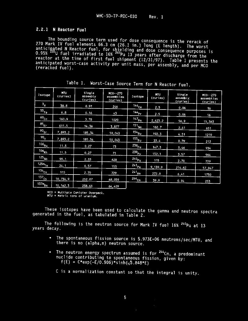
The irr diated fuel contains large quantities of fission products, such
extent, it also contains cladding activation products, such as 6oCo. A bounding worst-case radiological source term has been defined and is given in Table 1.
as 137Cs and $0 Sr, and actinides, such as 39Pu, z40Pu, and 241Pu. To a lesser
2

WHC-SD-TP-PDC-030 Rev. 1
Figure 1. MCO Preliminary Design Description.
/Juuu//-
asket 1 13'
t- 24" --+
Not to Sca le
3


WHC-SD-TP-PDC-030 Rev. 1
Table 4. Heat Source Term f o r Acc ident Cond i t ions .
Pay1 oad
Maximum
Minimum
Surface heat f l u x Total watts Sur face heat f l u x at center a t remainder o f MCO per MCO s e c t i o n o f MCO
s i d e w a l l s i d e w a l l
30.0 W/ft2 12.7 W/ft2 1200
0 0 0
The s u r f a c e heat f l u x a t t he MCO top and bottom i s t h e same as d e f i n e d f o r t h e normal t r a n s p o r t c o n d i t i o n s . The v a r i a t i o n i n heat f l u x w i t h l o c a t i o n on t h e MCO c i rcumference can be ignored d u r i n g t h e acc ident t r a n s i e n t .
~~ ~
Payload c o n f i g u r a t i o n
MCO l e n g t h - - i n .
MCO d iameter - - in .
MCO w a l l - - i n .
MCO vo l ume--gal
MCO empty--1 b
Basket weight--1 b
MCO top IO- in . s h i e l d
2.5.2 MCO Sur face Emi t tance
F i g u r e 1
160
24
0.38
272
1,540
500
1,230 l b
F o r t h e purpose o f c a l c u l a t i n g r a d i a t i v e heat t r a n s f e r between t h e MCO and t h e packaging system, the sur face emi t tance o f t h e MCO sur faces s h a l l be assumed t o be 0.25.
2.5.3 Payload and MCO Thermal Mass
No c r e d i t f o r t h e thermal mass o f t he payload s h a l l be taken when c a l c u l a t i n g t h e t r a n s i e n t performance o f t h e packaging system under e i t h e r t h e normal c o n d i t i o n s o f t r a n s p o r t o r t he acc ident c o n d i t i o n s , as d e f i n e d i n S e c t i o n 5.1. The thermal mass o f t he MCO s h e l l may be inc luded.
2.5.4 MCO Dimensions and Gross Weight
elements) t o be assumed f o r t he thermal c a l c u l a t i o n s i s d e f i n e d i n Table 5. The dimensions o f t h e MCO and i t s gross weight ( i n c l u d i n g t h e f u e l
Table 5. P r e l i m i n a r y Dimensions and Weight o f t h e MCO.
8


WHC-SD-TP-PDC-030 Rev.’ 1
Contaminant
Beta-gama emitt ing radionuclides; a l t radionuclides u i t h h a l f - l i v e s less than ten days; natural uranium; natural thorium; uraniun-235; uranim-238; thoriun-232; thor im-228 and thoriun-230 uhen contained in ores or physical concentrates
A I L other alpha emitt ing radionuclides
c a p a b i l i t i e s . The MCO may be p laced i n t o t h e MCO cask p r i o r t o t h e l o a d i n g o f t h e re racked f u e l baskets i n t o t h e MCO. The f u e l baskets s h a l l be prepared, as necessary, f o r t h e c o n d i t i o n i n g process p r i o r t o be ing loaded i n t o t h e MCO. F u r t h e r c o n d i t i o n i n g o f t h e f u e l , such as vacuum d ry ing , may t a k e p lace w i t h t h e MCO i n t h e cask. The cask w i l l be d r a i n e d and t h e MCO c o l d vacuum d r i e d p r i o r t o placement on t h e conveyance. The package s h a l l be mounted on t h e t r a n s f e r v e h i c l e b e f o r e l e a v i n g t h e bas in . l i m i t s must be met, as shown i n Table 6, p r i o r t o t r a n s p o r t a t i o n . P r i o r t o reuse o f t h e cask, t h e cask i n t e r n a l c a v i t y s h a l l be decontaminated t o l e s s than 100 t imes t h e removable contaminat ion l i m i t s s e t f o r t h i n Tab le 6. F igu re 4 prov ides a ske tch o f t h e K East and K West l o a d i n g areas, which a re i d e n t i c a l . improve t h e f u e l - l o a d i n g and package-handl ing c a p a b i l i t i e s o f t h e f a c i l i t y .
The e x t e r i o r package contaminat ion
L i m i t e d m o d i f i c a t i o n s o f t h e l o a d i n g area may be necessary t o
M a x i m permissible l i m i t s
2 dpn/cm2 pCi/cm
22
10-6 2 .2
Table 6 . Externa l Cask Contaminat ion L i m i t s .
Source: 49 CFR 173, 1994, “Shippers--General Requirements for sh iwents and Packagings, Code of Federal Requlations, BE amended.
173.443 I “Contamination contro I . I a
3.2 DESTINATION SITE--CSB
O f f l o a d i n g o f t h e package s h a l l t a k e p lace a t t h e CSB (F igu re 5) i n t h e 200 East Area. Th is a c t i v i t y s h a l l i n v o l v e t h e removal o f t h e MCO f rom t h e package. The MCO w i l l be staged a t t h e CSB, p o s s i b l y undergo f u r t h e r c o n d i t i o n i n g i n a separate c o n d i t i o n i n g f a c i l i t y , and then be r e t u r n e d f o r s to rage i n t h e CSB. The packaging s h a l l a l s o be decontaminated t o Tab le 6 l i m i t s and inspected, as needed, be fo re t r a n s p o r t back t o t h e K Basins.
11


WHC-SD-TP-PDC-030 Rev. 1
4.0 PACKAGING/TRANSPORT SYSTEM DESIGN
4 . 1 GENERAL
The packaging s h a l l be approved f o r use w i t h i n t h e boundar ies o f t h e Hanford S i t e . I t w i l l be au tho r i zed t o t r a n s f e r Type B, HRCQ o f f i s s i l e r a d i o a c t i v e m a t e r i a l i n t h e form o f i r r a d i a t e d f u e l assembl ies. A SARP s h a l l be w r i t t e n t o demonstrate t h e s a f e t y o f t h e t r a n s f e r t h rough a combina t ion o f cask performance and a d m i n i s t r a t i v e c o n t r o l s as p e r t h e Repor t on E q u i v a l e n t S a f e t y f o r O n s i t e Packaging and T r a n s p o r t a t i o n (WHC 1994). The SARP w i l l i n c l u d e t h e e v a l u a t i o n o f t h e packaging system t o p r o v i d e containment, s h i e l d i n g , and s u b c r i t i c a l i t y f o r t h e pay load d u r i n g normal (Sec t i on 5.1.1) and acc iden t c o n d i t i o n s (Sec t i on 5 . 1 . 2 ) . The package and t r a n s p o r t a t i o n s h a l l be per formed i n accordance w i t h WHC-CM-2-14, Hazardous M a t e r i a l S h i p p i n g and Packaging Manual. Approval o f t h e SARP p rov ides a u t h o r i z a t i o n f o r o n s i t e t r a n s p o r t .
4.2 PACKAGING DESIGN CRITERIA
The packaging s h a l l be designed as a reusab le system capable o f be ing loaded and unloaded bo th i n a i r and underwater. The MCO cask s h a l l be capable o f c a r r y i n g a t l e a s t one MCO. t h e MCO i s capable o f be ing loaded w i t h i r r a d i a t e d f u e l e lements i n baskets be fo re o r a f t e r t h e MCO i s p laced i n t h e i n n e r c a v i t y o f t h e cask. The MCO cask des ign s h a l l be such t h a t t h e MCO may be welded a f t e r be ing loaded i n t o t h e packaging c a v i t y . des ign s h a l l a l l o w d r a i n i n g o f water f rom t h e cask c a v i t y p r i o r t o t r a n s p o r t .
c o n d i t i o n s w i l l be v e r i f i e d th rough ana lys i s , o r a combinat ion o f a n a l y t i c a l and t e s t methods, f o r a bounding case scenar io . The r e s u l t s s h a l l demonstrate t h a t any m a t e r i a l r e l e a s e f a l l s w i t h i n t h e dose consequence l i m i t s o f Sec t i on 5.1.2.1.
The des ign o f t h e MCO cask s h a l l be such t h a t
The cask may be t o p and/or bot tom loaded. The cask
Package performance requi rements d u r i n g normal and acc iden t t r a n s p o r t
4.2.1 Packaging M a t e r i a l s
The s t r u c t u r a l containment boundary m a t e r i a l s f o r t h e packaging s h a l l comply w i t h m a t e r i a l requi rements i d e n t i f i e d i n NUREG/CR-3854, f a b r i c a t i o n C r i t e r i a f o r S h i p p i n g Conta iners (F i sche r and L a i 1985). The m a t e r i a l s o f c o n s t r u c t i o n s h a l l meet t h e f r a c t u r e toughness requi rements o f Regu la to ry Guide 7.11 (NRC 1991a) o r Regu la to ry Guide 7.12 (NRC 1991b), as a p p l i c a b l e . There s h a l l be an e q u i v a l e n t w a l l t h i c k n e s s ( a l l w a l l m a t e r i a l s ) o f a t l e a s t 7.62-cm (3 - in . ) s t e e l , based on punc ture r e s i s t a n c e th resho lds .
be American S o c i e t y o f Mechanical Engineers (ASME) o r American S o c i e t y f o r T e s t i n g and M a t e r i a l s (ASTM)-cer t i f ied m a t e r i a l s o r o t h e r recogn ized n a t i o n a l o r i n d u s t r i a l s tandards f o r m a t e r i a l s o t h e r than s t e e l o r s t a i n l e s s s t e e l . The m a t e r i a l s s h a l l be compat ib le w i t h o r p rov ide adequate r e s i s t a n c e t o t h e
A l l m a t e r i a l s , i n c l u d i n g l e a d ( i f r e q u i r e d f o r s h i e l d i n g purposes), s h a l l
14

WHC-SD-TP-PDC-030 Rev. I
corrosive effects of materials (liquids, vapors, gases, and solids) that they will be in contact with throughout their life cycle (20 years). The materials shall also be selected to minimize chemical-galvanic reactions between payload components and the packaging.
4.2.2 Fabrication Methods
NUREG/CR-3854 (Fischer and Lai 1985), shall be followed. Fabrication of the packaging shall be performed in accordance with ASME (1992) Section 111, as required by NUREG/CR-3854.
Welds shall be inspected per ASME (1992) Section V. Welders shall be qualified per ASME (1992) Section I X .
Fabrication criteria for a Category I packaging, as delineated in
All welds and weld joints shall be examined per ASME (1992) Section 111.
All welds shall be sufficiently smooth to enable easy decontamination. The design shall consider avoiding potential contamination traps to the greatest extent practicable. All containment welds shall be radiographed per ASME requirements.
Decontamination of all external surfaces will be required to meet Table 6 limits.
4.2.3 Packaging Dimensions
The dimensions for the internal cavity of the packaging must be sufficient to accommodate the MCO. 406 cm (160 in.) long by 61 cm (24 in.) in diameter.
handling limits of the K Basins and CSB, shown in Figures 4 and 5 .
The MCO concept' maximum dimensions are
The maximum dimensions for the packaging exterior shall be based on the
4.2.4 Maximum Gross Weight
The weight of a package fully loaded with reracked fuel, water, etc., shall not exceed 27,210 kg (60,000 lb). The package shall be configured to be handled with the K Basin crane. The maximum lifting capacity of this crane i s 27,210 kg (30 tons).
4.2.5 Lifting and Tiedown Attachments
The lifting attachments for the packaging shall be capable of lifting three times the total suspended weight without generating a combined stress or maximum tensile stress at any point in the load path in excess of the corresponding minimum yield strength of their materials o f construction. lifting attachments shall be compatible with the cranes in the K Basins loadout area, CSB cranes, and portable cranes t o permit field lifting o f the packaging.
The
15

WHC-SD-TP-PDC-030 Rev. 1
I f t h e t iedown attachments a r e a s t r u c t u r a l p a r t o f t h e packaging, t hey s h a l l be designed t o w i ths tand a f o r c e o f t e n t imes t h e package we igh t i n t h e fo rward and a f t d i r e c t i o n s ; f i v e t imes t h e gross package we igh t i n t h e l a t e r a l d i r e c t i o n s ; and t w o t i m e s t h e package we igh t i n t h e v e r t i c a l d i r e c t i o n s w i t h o u t y i e l d i n g .
4.2.6 Ven t ing
c a v i t y . be ing c losed and l e a k t i g h t d u r i n g normal t r a n s p o r t c o n d i t i o n s . Dur ing and subsequent t o acc iden t c o n d i t i o n s , t h e r e l e a s e o f m a t e r i a l s f rom t h e package, i n c l u d i n g t h e v e n t i n g system, s h a l l n o t exceed t h e l i m i t s s e t i n Sec t i on 5.1.2.
The packaging des ign s h a l l i n c o r p o r a t e vents f o r sampling t h e cask Any vents t h a t a re i nco rpo ra ted i n t h e des ign must be capable o f
4.2.7 Loading
The packaging s h a l l be capable o f be ing loaded underwater o r i n a i r . packaging s h a l l be capable o f be ing top- loaded w i t h an empty o r f u l l MCO o r bottom-loaded w i t h a f u l l MCO.
The
4.2.8 D r a i n i n g
The packaging s h a l l be o u t f i t t e d w i t h a d r a i n p o r t and h i g h p o r t ven t t h a t w i l l p e r m i t removal o f l i q u i d s f rom t h e cask c a v i t y w i t h o r w i t h o u t a f u l l y loaded MCO loaded i n t o t h e cask. s h a l l be capable o f be ing opened and c losed us ing remote hand l i ng equipment.
The d r a i n p o r t and h i g h p o r t ven t
4.2 .9 Water C i r c u l a t i o n
The packaging s h a l l be equipped w i t h fea tu res t h a t p e r m i t c i r c u l a t i o n o f a minimum o f 76 L/min (20 gpm), 50 'C (122 O F ) , water th rough t h e package/MCO annulus f o r t h e c o l d vacuum d r y i n g process. u n i f o r m water temperature f l o w around t h e MCO. The system s h a l l p r o v i d e double s h u t - o f f q u i c k re lease i n t e r f a c e s t o t h e i n l e t and o u t l e t p o r t s on t h e cask. The des ign s h a l l i n c l u d e f e a t u r e s t h a t w i l l r e t a i n t h e MCO i n t h e packaging f o r a l l normal and o f f -normal pressures i n t h e annulus.
Th is f e a t u r e s h a l l p r o v i d e a
4.2.10 Closu re
Each packaging c l o s u r e s h a l l be secu re l y c losed w i t h a p o s i t i v e f a s t e n i n g dev i ce t h a t cannot be opened u n i n t e n t i o n a l l y . outermost containment boundary must i n c o r p o r a t e tamper - i nd i ca t i ng f e a t u r e s . The cask pay load c a v i t y s h a l l be prov ided w i t h t h e c a p a b i l i t y t o be f i l l e d and purged w i t h i n e r t gas.
A d d i t i o n a l l y , t h e
16

WHC-SD-TP-PDC-030 Rev. 1
4.2.11 Containment
The MCO cask shall provide the transportation containment barrier for the payload, as described below., The MCO will provide one additional level of containment. conditions (Section 5.1.1), the package remains leaktight, as demonstrated through testing and/or analysis. Linear-elastic analysis may be performed to demonstrate maintenance of the leakage rate after the normal transfer conditions. ASME (1992) Section 111, Service Level A stress allowables shall be used for analytical acceptance.
The packaging shall be designed so that during normal transfer
The cask system shall also be designed such that, during accident conditions (Section 5.1.2) the package maintains a single confinement barrier for the MCO, as demonstrated by analysis and/or testing. Elastic-plastic analysis may be performed to demonstrate maintenance of confinement after the. accident conditions. ASME (1992) Section 111, Service Level D, stress allowables shall be used for analytical acceptance. Energy absorbed by the package during the drop is accounted for based on elastic-plastic analysis. During the fire scenario, the MCO cask seals may deteriorate such that loss of the cask containment seal occurs.
4.2.12 Shielding
factor for the design dose rate o f the package. (lid, vent ports, leak test ports, etc.) shall be designed to ensure that they provide adequate shielding.
As low as reasonably achievable (ALARA) principles will be the limiting The packaging and closures
4.2.13 Maintenance
The packaging and ancillary components shall be designed to minimize maintenance or testing requirements. Features requiring maintenance shall be designed in accordance with ALARA principles using the guidance found in HSRCM-1, Hanford S i t e Radiological Control Manual.
4.2.14 Life Cycle
The packaging shall be capable of being reused a minimum of 1,000 times. The MCO is used only one time for transportation and is the long-term storage container. Additionally, the packaging shall have a minimum transport service life of 20 years. maintenance, refurbishing, and decontamination procedures required for packaging reuse. Features requiring refurbishment prior to reuse shall be designed in accordance with ALARA principles, as per HSRCM-1.
The SARP will provide the necessary requirements, such as inspections and part replacements, to allow for the safe and effective reuse of the cask.
Design features of the packaging shall minimize
17


WHC-SD-TP-PDC-030 Rev. 1
Mode
Road
4.4 TIEDOWN SYSTEM
Long i tud ina l L a t e r a l V e r t i c a l
t 2g t/- lg 39 down, 2g up
An engineered t iedown system s h a l l be used t o secure t h e packaging system t o t h e t r a n s p o r t v e h i c l e ( s ) . and be des igned p e r t h e I n t e r n a t i o n a l Atomic Energy Agency S a f e t y S e r i e s 37 ( I A E A 1990). The t iedown at tachments f o r those requi rements s h a l l be capable o f r e s i s t i n g t h e f o r c e s f o r road o r r a i l , as descr ibed i n Tab le 7.
The t iedown system s h a l l meet t h e requ i rements
Table 7. Load Fac tors f o r Tiedown Systems.
Cons ide ra t i on s h a l l be g i v e n t o t iedown methods (such as remote opera t i ons o r permanent systems i n t e g r a l t o t h e packaging and t r a n s p o r t v e h i c l e ) t o maximize t h e d i s tance and/or min imize t h e t ime spent near t h e pay1 oad.
5.0 GENERAL REQUIREMENTS
5.1 TRANSPORTATION SYSTEM
5.1.1 Normal Cond i t i ons of Trans fer
t h e packaging des ign f o r i t s a b i l i t y t o ma in ta in containment, s h i e l d i n g , and n u c l e a r c r i t i c a l i t y c o n t r o l when sub jec ted t o t h e f o l l o w i n g c o n d i t i o n s .
For c o n d i t i o n s no rma l l y i n c i d e n t t o t r a n s p o r t , t h e SARP s h a l l e v a l u a t e
Environmental Cond i t ions . The des ign temperature 1 i m i t s f o r t h e i n d i v i d u a l components, p a r t s , and m a t e r i a l s o f t h e package s h a l l be determined by analyses and/or t e s t i n g . The analyses and/or t e s t s s h a l l be based upon t h e c o n d i t i o n s l i s t e d below. The o p e r a t i o n a l temperatures s h a l l be shown t o n o t exceed t h e des ign l i m i t s . The ambient temperatures a t t h e Hanford S i t e f o r t h e peak summer month a re t a b u l a t e d i n Table 8.
19

WHC-SD-TP-PDC-030 Rev. 1
N
0
57
35
42
45
42
35
57
0
Table 8. Hanford A i r Temperature.
Vertical surfaces facing
NE E SE S su 0 0 0 0 0
192 21 1 105 17 17
173 268 208 42 32
56 177 213 126 45
45 49 120 167 120
42 42 45 126 213
32 32 32 42 208
17 17 17 17 105
0 0 0 0 0
- Maximum heat genera t i on r a t e o f worst-case source f rom Sec t ion 2.2 p l u s maximum s o l a r heat l o a d (see Table 9) p l u s maximum a i r temperature o f 46 " C (115 O F )
Minimum a i r temperature o f -33 "C (-27 O F ) p l u s maximum heat genera t i on r a t e f rom worst-case source i n Sec t i on 2 . 2
- Minimum a i r temperature o f -33 " C (-27 O F ) and zero heat genera t i on r a t e .
-
Table 9. Maximum S o l a r R a d i a t i o n Received f rom t h e Sun (BTU/h- f t2) .
T i m e
4 a.m.
6 a.m.
8 a.m.
10 a.m.
12 noon
2 p.m.
4 p.m.
6 p.m.
8 p.m.
- U
0
17
32
42
49
177
268
21 1
0
-
-
- NU
0
17
32
42
45
56
173
192
0
-
-
surface facing u
Maximum normal o p e r a t i n g o u t s i d e su r face temperature o f t h e cask s h a l l be less t han 82 "C (180 O F ) i n maximum a i r tempera ture and i n t h e shade.
20


WHC-SO-TP-PDC-030 Rev. 1
5.1.1.3 Criticality. The package design shall also ensure that twice the number of packages will meet the following criteria.
The contents shall remain subcritical (k,,, less than 0.95, where 0.95 is the mean value plus two times the one standard deviation value [two standard deviations] with bias applied) for the packages during normal conditions of transport, as described in Section 5.1.1, also assuming the following.
The most reactive credible configuration is consistent with the chemical and physical form of the allowed packaged material.
There is clustering of packages and close reflection of the package array by water on all sides.
5.1.2 Accident Conditions
The report on equivalent safety (WHC 1994) provides a description of how a highly controlled transportation environment, such as that available on the Hanford Reservation, can contribute to the safety o f a packaging system. H&R (1995) uses accident data from the Hanford Site and other controlled transportation environments6to establish the worst-case credible accidents (frequency greater than 10- accidentslyear) for the packaging system.
Based on the preliminary risk evaluation (Green 1995), the following worst-case accidents meet the equivalent safety-based design criteria. purposes of onsite package evaluation, these events are assumed to occur nonsequentially. For design evaluation, these accidents shall be evaluated at an ambient temperature between -32 "C (-27 O F ) and 47 "C (115 OF), whichever was more severe for the individual incident. Additionally, the packaging system will be evaluated carrying the worst-case payload, as described in Section 2.0.
For
Impact. be simulated by a free drop of 30 ft onto an 8-in.-thick concrete surface with a concrete strength of 4,000 psi and a Soil Modulus of Elasticity of 28,000 psi with a yield of 60,000 psi and 0.875-in. reinforcement rebar (No. 7) spaced 12 in. apart with 2-in. cover, each way, each face. The package shall impact in an orientation expected to cause maximum damage. greater than 1OOg's during this drop scenario. Energy absorption devices, i f necessary, to reduce the g-loading shall be an integral part of the packaging and not involve additional operational steps. The energy absorbers must be easily replaceable and not require maintenance.
Puncture. The worst-case credible puncture incident is equivalent to a free drop of the packaging through a distance of 1 m (40 in.) in a position expected to cause the maximum damage, onto the upper end of a solid, vertical, cylindrical, mild-steel bar mounted on an essentially unyielding, horizontal surface. The bar must be 15 cm (6 in.) in diameter, with the top horizontal and its edge rounded to
The worst-case credible impact for the packaging system may
The MCO shall not be exposed to
22

WHC-SD-TP-PDC-030 Rev. 1
a r a d i u s o f n o t more than 6 mm (1/4 i n . ) and o f a l e n g t h t o cause maximum damage t o t h e package, b u t n o t l e s s than 20 cm (8 in . ) l ong . Acceptance t o t h i s requi rement i s t h a t t h e r e i s no l o s s o f s h i e l d i n g t o t h e e x t e n t shown below i n Sec t i on 5.1.2.2.
minutes t o a BOO 'C (1,475 " F ) engu l f i ng f i r e t h a t has an e m i s s i v i t y c o e f f i c i e n t o f 0.9. The su r face a b s o r p t i v i t y o f t h e package s h a l l be t h e g r e a t e r o f t h e a n t i c i p a t e d a b s o r p t i v i t y o r 0.8. can be assumed t o be cooled a f t e r t h e f i r e . system f o r t h e packaging s h a l l be assumed t o be i n o p e r a t i v e d u r i n g t h e f i r e .
Thermal. Exposure of t h e packaging system f o r n o t l e s s than 30
The package Any a c t i v e c o o l i n g
A c t i v e c o o l i n g o f t h e package f o l l o w i n g t h e 30-minute f i r e can be assumed. I f assumed, t h e a c t i v e c o o l i n g s h a l l c o n s i s t of quenching t h e o u t e r package sur faces us ing water spray f rom a f i r e hose r a t e d a t 125 ga l /min . Flow a t t h i s maximum f l o w r a t e s h a l l be assumed t o occur f o r a maximum o f 45 minutes. I f needed, a d d i t i o n a l quenching water f l o w can be assumed f o r an a d d i t i o n a l p e r i o d o f 100 minutes a t a maximum f l o w r a t e o f 50 ga l /min . Assume a water temperature o f 29 " C (85 O F ) f o r t h i s procedure.
5.1.2.1 Containment. Dur ing and subsequent t o a l l c r e d i b l e o r p robab le acc iden t events , as descr ibed i n Sec t ion 5.1.2, t h e packaging system s h a l l m a i n t a i n conf inement o f t h e MCO (no t a l l o w t h e MCO t o be re leased f rom t h e cask) and n o t a l l o w a c a t a s t r o p h i c r e l e a s e o f r a d i o a c t i v e m a t e r i a l t o t h e environment ( re lease t h e f u e l e lements f rom t h e cask and MCO). r i s k e v a l u a t i o n w i l l suppor t t h e c r e d i b l e acc ident scenar ios .
5.1.2.2 S h i e l d i n g . Subsequent t o a l l c r e d i b l e o r p robab le acc iden t events , as desc r ibed i n Sec t i on 5.1.2, t h e dose 1 m (3 .3 ft) f rom t h e su r face o f t h e packaging system s h a l l n o t exceed 1 rem/hr . Due t o t h e f i r e event, t h e r e s h a l l be no n e t loss o f l e a d s h i e l d i n g , if l e a d i s used. The l e a d may me l t , b u t cannot be l o s t .
5.1.2.3 C r i t i c a l i t y . Subsequent t o a l l c r e d i b l e o r p robab le acc iden t events , as desc r ibed i n Sec t i on 5.1.2, t h e packaging system s h a l l be eva lua ted f o r one package t o meet t h e f o l l o w i n g c r i t e r i a .
A r a d i o l o g i c a l
The con ten ts s h a l l remain s u b c r i t i c a l (k,,,,less than 0.95, as d e f i n e d i n Sec t i on 5.1.1.3) f o r t h e packaging system d u r i n g and subsequent t o an acc iden t condi t . ion, a l s o assuming t h e f o l l o w i n g .
The f i s s i l e m a t e r i a l i s i n t h e most r e a c t i v e c r e d i b l e c o n f i g u r a t i o n c o n s i s t e n t w i t h t h e chemical fo rm and damaged c o n d i t i o n o f t h e package and payload.
There i s optimum i n t e r s p e r s e d aqueous moderat ion.
There i s c l u s t e r i n g o f packages and c l o s e r e f l e c t i o n o f t h e package a r r a y by water on a l l s ides .
5.1.2.4 R i s k Eva lua t i on . The p r e l i m i n a r y r i s k e v a l u a t i o n was per formed t o e s t a b l i s h t h e e q u i v a l e n t safety-based des ign c r i t e r i a . T h i s assessment was
23

WHC-SD-TP-PDC-030 Rev. 1
used t o deve lop t h e des ign c r i t e r i a s t a t e d i n 5.1.2. A r a d i o l o g i c a l r i s k e v a l u a t i o n w i l l be developed f o r t h e SARP and w i l l eva lua te c r e d i b l e acc iden t scenar ios t o meet t h e o n s i t e t r a n s p o r t a t i o n s a f e t y c r i t e r i a .
5 . 2 ALARA
The des ign f e a t u r e s o f t h e packages s h a l l be c o n s i s t e n t w i t h t h e requ i rements o f WHC Occupat ional ALARA Program (WHC 1995), f o r t h e Hanford S i t e . Exposure o f personnel t o r a d i o l o g i c a l and o t h e r hazardous m a t e r i a l s assoc ia ted w i t h t h e load ing , c losure , t iedown, t r a n s f e r , and o f f - l o a d i n g o f t h e package s h a l l be min imized. Cost b e n e f i t analyses shou ld be performed, as needed, t o determine t h e bes t ba lance between exposure and economical des ign .
be met p r i o r t o t r a n s p o r t o f t h e packaging. The contaminat ion l i m i t s , as d i r e c t e d by 49 CFR 173.443 (Table 6), w i l l
5.3 QA
The QA program requi rements f o r a c t i v i t i e s such as des ign, procurement, f a b r i c a t i o n , i nspec t i on , t e s t i n g , component hand l ing , and documentat ion o f t h e f u e l casks and t h e i r components s h a l l be e q u i v a l e n t t o 10 CFR 71, Subpar t H, and WHC-CM-4-2, Q u a l i t y Assurance Manual.
used t o d e f i n e t h e s a f e t y c l a s s o f b o t h t h e system and i n d i v i d u a l components o f t h e packaging system. documented i n WHC-CM-4-46, Nonreac tor F a c i l i t y S a f e t y A n a l y s i s Manual. The c r i t e r i a f o r t r a n s p o r t a t i o n s a f e t y c l a s s eva lua t i ons a re documented i n WHC-SD-TP-RPT-001 (WHC 1994). QA requi rements s h a l l be developed f o r t h e procurement, f a b r i c a t i o n , and i n s p e c t i o n o f t h e package based on t h e ass igned t r a n s p o r t a t i o n s a f e t y c l a s s o f t h e package.
To e s t a b l i s h a QA p l a n f o r t h e packagings, a graded approach s h a l l be
The a p p l i c a t i o n o f t h e s a f e t y c l a s s system i s f u l l y
5.3 .1 System S a f e t y Class
The t r a n s p o r t a t i o n s a f e t y c l a s s o f t h e packages w i t h a worst-case pay load was de termined by a dose consequence s tudy, documented i n Appendix A. T h i s s tudy assumed a t o t a l f a i l u r e o f t h e c a n i s t e r packaging system and t h e r e l e a s e o f a l l o f i t s con ten ts t o t h e environment a t t h e wors t p o s s i b l e l o c a t i o n on t h e t r a n s p o r t a t i o n r o u t e . For t h e shipment o f t h e i r r a d i a t e d f u e l , t h e wors t - case r e l e a s e l o c a t i o n i s w i t h i n t h e 100 K Area, j u s t o u t s i d e t h e bas ins.
per formed f o r 270 elements i n t h e r e r a c k basket scenar io , i n d i c a t e s t h a t t h e maximum i n h a l a t i o n dose t o an o n s i t e r e c e p t o r i s 240,000 rem e f f e c t i v e dose e q u i v a l e n t (EDE), and t h e maximum i n h a l a t i o n dose t o an o f f s i t e r e c e p t o r i s 120 rem EDE. Therefore, f o r 270 re racked elements, t h e packaging c o n s t i t u t e s a S a f e t y Class 1 system p e r WHC-SD-TP-RPT-001 (WHC 1994) and WHC-CM-4-46.
The t r a n s p o r t a t i o n s a f e t y c l a s s dose consequence s tudy (Appendix A ) ,
For t r a n s p o r t a t i o n packages w i t h HRCQ m a t e r i a l and a Sa fe ty Class 1, ASME (1992) Sec t i on 111 s h a l l be used as g u i d e l i n e s f o r t h e des ign.
24


WHC-SD-TP-PDC-030 Rev. 1
The f u e l t h a t i s be ing s t o r e d i n t h e K Basins Ss s t o r e d i n double b a r r e l l e d c a n i s t e r s t h a t c o n t a i n up t o 14 N Reactor f u e l assembl ies. i s removed f rom these c a n i s t e r s and p laced i n baskets i n s i d e o f t h e MCO. maximum o f 270 assembl ies w i l l be p l a c e d i n these baskets .
The f u e l A
4.1 RADIOACTIVE INVENTORY
The i n v e n t o r y i n t h e baskets i s con ta ined w i t h i n t h e MCO. The MCO a c t s Table 1 shows t h e a n t i c i p a t e d a c t i v i t y p e r as t h e p r imary c o n t a i n e r vesse l .
u n i t mass, p e r assembly, and p e r cask. The cask con ta ins a t o t a l o f 270 assembl ies.
Table 1. Worst-case Source Term f o r N Reactor Fue l . (p rov ided by t h e customer)
Mco = Mul t ip le canister overpack. MTU = Metric ton of u r a n i m .
5.0 ACCIDENT SCENARIOS/INITIATING EVENTS
The bounding c o n d i t i o n considered f o r t h e acc iden t scenar io i s a f i r e acc iden t .
The p o s s i b l e causes o f f i r e acc iden ts a re as f o l l o w s .
Uranium and uranium hyd r ide i n powder form have been shown t o i g n i t e i n a i r , i n some cases even f o r i n i t i a l room-temperature c o n d i t i o n s (Peacock 1992 and Hartmann e t a l . 1951) .
A-2

WHC-SD-TP-PDC-030 Rev. 1
The s h i p p i n g cask con ta ins N Reactor f u e l assembl ies i n s i d e a water- f i l l e d s h i p p i n g c o n t a i n e r . ou t , l e a v i n g t h e assembly dry and access ib le t o a i r . o f t h e N Reactor f u e l t o a i r may r e s u l t i n a f i r e .
The sh ipp ing c o n t a i n e r f a i l s a long t h e bot tom weld, and t h e water d r a i n s out , caus ing t h e f u e l t o become d r y and exposed t o a i r . t h e f u e l i s dry, t h e r e i s a p o t e n t i a l f o r r e s i d u a l h y d r i d e t o r e a c t w i th a i r , i g n i t e , and burn.
The water i n t h e c a n i s t e r c o u l d l e a k The exposure
Once
The p o s s i b i l i t y e x i s t s t h a t t h e t r u c k f u e l c o u l d c a t c h f i r e due t o t r a f f i c acc idents .
I n t h e acc iden t pos tu la ted , a l l o f t h e f u e l i n t h e MCO i s assumed t o be exposed and surrounded by f i r e .
5 .1 RELEASE FRACTION
An a i r b o r n e r e l e a s e f r a c t i o n (ARF) o f 5.0 x (DOE 1994, pp. 4-37) i s used t o c a l c u l a t e t h e doses a t t h e o n s i t e and o f f s i t e r e c e p t o r l o c a t i o n s f o r t h e f i r e scenar io . assoc ia ted w i t h o x i d a t i o n o f uranium. The 5 x 10- was se lec ted because i t i s t h e most conserva t i ve va lue . r a d i o n u c l i d e s present , except f o r cesium, ruthenium, and t e l l u r i u m , which a re cons idered s e m i v o l a t i l e . The re lease f r a c t i o n f o r ru then ium and t e l l u r i u m was taken t o be 1 x (DOE 1992, p. A-9). The re lease f r a c t i o n f o r cesium was taken t o be 0.09 (DOE 1994). The re lease f r a c t i o n f o r k r y p t o n and t r i t i u m was taken t o be 1.0 (DOE 1992, p. A-9).
The q u a n t i t y o f a i r b o r n e r a d i o a c t i v e m a t e r i a l re leased f rom t h e f i r e i s t h e r e f o r e equal t o t h e a c t i v i t y o f each r a d i o n u c l i d e l i s t e d i n Tab le 1 t imes t h e r e l e a s e f r a c t i o n .
T h i s re lease f r a c t i o n was take? f rom DOE (1994) and i s
T h i s r e l e a s e f r a c t i o n i s a p p l i e d t o a l l
The worst-case source te rm f o r N Reactor f u e l , a d j u s t i n g f o r t h e a i r b o r n e r e l e a s e f r a c t i o n , i s g i v e n i n Table 2.
A-3


WHC-SO-TP-PDC-030 Rev. 1
Receptor
Ons i te (100 m E) Near r i ve rbank ' (150 N W )
O f f s i t e (11.7 km W ) '
7 .0 RESULTS
/Q (s/m3) 7.32 E-02
1.54 E-02
3.70 E-05
The s a f e t y c l a s s f o r t h e K Basin cask t r a n s p o r t i n g N Reactor f u e l assembl ies was determined i n accordance w i t h t h e guidance p rov ided i n WHC-CM-4-46, 9.0, Rev. 0, "Ass ign ing S a f e t y Classes t o Systems, Components and S t r u c t u r e s . " I n t h e case o f r a d i o a c t i v e m a t e r i a l s , t h e f a i l u r e o f a system o r component t h a t c o u l d r e s u l t i n an o f f s i t e p u b l i c exposure i n excess o f 500 mrem e f f e c t i v e dose e q u i v a l e n t i s c l a s s i f i e d as Safe ty Class 1. guidance f o r making a s a f e t y c l a s s de te rm ina t ion f o r a f a c i l i t y o r a system i n d i c a t e s t h a t t h e s a f e t y c l a s s i f i c a t i o n i s based upon t h e d e t e r m i n a t i o n o f consequences o f p o t e n t i a l acc idents w i t h o u t t h e m i t i g a t i o n p rov ided by engineered o r a d m i n i s t r a t i v e b a r r i e r s . I n a d d i t i o n , t h e e n t i r e i n v e n t o r i e s o f hazardous m a t e r i a l s a l lowed i n t h e f a c i l i t y o r t h e system a re assumed t o be p resen t .
The
Atmospheric d i s p e r s i o n f a c t o r , X/Qs, f o r t h e o n s i t e and o f f s i t e r e c e p t o r s were taken f rom Savino (1995). The o n s i t e r e c e p t o r i s l o c a t e d 100 m f rom t h e source; t h e o f f s i t e r e c e p t o r i s 11,730 m west o f t h e K Basins ( c u r r e n t s i t e boundary). maximum o f f s i t e r e c e p t o r X / Q va lue i s 1.54E-02 s / m , which i s assoc ia ted w i t h a r e c e p t o r a t 150 m i n t h e nor thwest d i r e c t i o n f rom t h e l O O K Area. c a l c u l a t e d va lues o f X / Q a re g i ven i n Table 3 f o r t h e o n s i t e and o f f s i t e r e c e p t o r s .
For t h e proposed s i t e boundary (see f o p n o t e s i n Tab le 3 ) , t h e
The
The va lues o f X / Q , as shown i n Tab le 3, a re used as i n p u t d a t a i n t o t h e G E N I I code f o r dose c a l c u l a t i o n s . The c a l c u l a t e d doses f o r t h e o n s i t e and o f f s i t e r e c e p t o r s a re g i v e n i n Table 4 .
A-5


WHC-SD-TP-PDC-030 Rev. 1
T I M E ~
1 Intake ends a f t e r (yr) 50 Dose calc. ends a f te r ( y r ) 0 Release ends a f t e r (yr) 0 0
No. of years of a i r deposit ion p r i o r t o the intake period No. of years of i r r i g a t i o n uater deposition p r i o r t o the intake period
FAR-FIELD SCENARIOS ( l F POPULATION DOSE) ~
0 D e f i n i t i o n option: 1-Use population g r i d i n f i l e POP.IN 0 2-use t o t a l entered on t h i s l i n e
NEAR-FIELD SCENARIOS ~
0
Pr io r t o the beginning of the intake period: ( y r ) Uhen was the inventory disposed? Uhen was LOIC?
(Package degradation s ta r t s ) (B io t i c transport s t a r t s )
Fraction of roots in upper s o i l ( top 15 cm) Fraction of roots i n deep s o i l Wanual red is t r ibut ion: deep soi l /surface s o i l d i l u t i o n factor Source area for external dose modif icat ion factor (m2)
1
7.32E-2 0 0 T
0 0 0
T T 0
EXPOSURE
0 0 0 0 0 0 0 1 .o
8766.0 0 0
====AIR TRANSPORT===ss;;lll=nrr;l;;-E;II;=.E;Ell==SECTION IF==== 0-Calculate PM I O Release type (0-3)
Option: 1-Use chi/0 or PM value Stack release ( T / F ) 2-select M I d i s t 8 d i r 1; Stack height (m)
stack flow (nWsec) stack radius ( r n )
3-Specify MI d i s t 8 d i r Chi/P o r PM value MI sector index (1.S) '0 Eff luent twp. (c) M I distance from release point ( m ) j O Bui lding x-section t m 2 ) Use j f data, ( T / F ) else chi/Q g r i d l o Building height (m)
Mixing r a t i o model: 0-use value, 1-river.. 2-lake -__- ----SURFACE UATER TRANSPORT;-I;===;;~;~=E==I~=;.....~= SECTION 2;z===
Mixing ra t i o , dimensionless Average r i v e r flow ra te for: YIXFLG=O (n13/s), MlXFLG=1,2 (m/s) Transit t i m e t o i r r i g a t i o n uithdranal locat ion (hr) If mixing r a t i o model > 0:
Rate of e f f luent discharge t o receiving water body ( f i l s ) Longshore distance from release point t o usage location (m) offshore distance t o the water intake (rn) Average water depth i n surface water body (m) Average r i v e r width t m ) , M I X F L G = l only Depth of e f f luent discharge point t o surface water (m), lake , only
_ _ _ _ ----WASTE FORM AVAILABILITY-=====r===================SE~TIO~ 3==;== Uaste form/package hal f Life, (y r ) Uaste thickness, (m) Depth of s o i l overburden, m
_ _ _ _ - - - -BIOTIC TRANSPORT OF BURIED SOURCE;=;=======ils;==SECTION &=s==
Consider during inventory decay/buildup period ( T / F ) ? Consider during intake period ( T / F ) ? ' 1 -A r id non ag r i cu l tu ra l Pre-Intake s i t e condi t ion .............. j 2-Humid mn agr i cu l tu ra l
I 3-Agr icu l tura l
_ _ _ _ ----EXTERNAL EXPOSUREiill=====il=====================SECTION 5===== Exposure t ime: I Residential i r r i g a t i o n :
Consider: ( T / F )
Application r a t e (in/yr) Duration (um/yr)
i T Source: 1-ground water 1 0 2-surface uater
P l u m (hr ) So i l contamination (hr) Sninming (hr)
shorel ine a c t i v i t i e s (hr) I 0 Boating (hr ) 1 0
Shoreline type: (1- r iver , 2-lake, 3-ocean, 4 - t i d a l basin) Transit t i m e for release t o reach aquatic recreation (h r ) Average f r a c t i o n of t i m e submersed i n acute cloud (hr/person h r )
HOUPS of exposure t o contamination per year 0-No r e m s - 1-Use Mass Loading 2-Use Anspsugh model
====]N"ALATI~N=======================================SECTION 6=r===
pension Mass loading factor (glm3) Top s o i l avai lable (cm)
A-8

WHC-SD-TP-PDC-030 Rev. 1
0 0
0 0 F
F
--__ ----INGESTION POPULATION;======;;==;E--r;z=.------.. 7===== Atmospheric production d e f i n i t i o n (se lec t option):
0-Use food-neighted chi/P,(focd-sec/n3), enter value on t h i s l i n e 1-Use population-ueighted c h i p 2-Use uniform production 3-Use c h i l a and production gr ids (PRODUCTION u i l l be overridden)
Population ingesting aquatic foods, 0 defaul ts t o t o t a l (person) Population ingesting dr ink ing uater, 0 defaul ts t o t o t a l (person) Consider dose from food exported out of region (default=F)
Note belou: S* or Source: 0-none, 1-ground nater, 2-surface Mater
---- APUATIC F W O S / DRINKING UATER INGESTION=========SECTION a====
Sal t uater? (default i s fresh)
3-Derived concentration entered above _ _ _ _
USE TRAN- PROD- -CONSUMPTION- ? FMX) S I T UCTION HOLDUP RATE T / F TYPE h r kg l y r da kWyr ... _--... _...- ..___.. ._.__- ____. F F I S H 0.00 O.OE+OO 0.00 0.0 F MOLLUS 0.00 O.OE+OO 0.00 0.0 F CRUSTA 0.00 O.OE+OO 0.00 0.0 . . . ~ ~ ...~ ... F PLANTS 0.00 O.OE+OO 0.00 0.0
DRINKING UATER
0 Sourcecsee above) T Treatment? T / F 0 Holdup/transit(dal 0 Consunption(L/yr)
F LEAF V 0.00 0 0.0 0.0 0.0 O.OE+OO 0.0 0.0 F R W T V 0.00 0 0.0 0.0 0.0 O.OE+OO 0.0 0.0 F FRUIT 0.00 0 0.0 0.0 0.0 O.OE+OO 0.0 0.0 F GRAIN 0.00 0 0.0 0.0 0.0 O.OE+OO 0.0 0.0
...HUMAN.--- TOTAL DRINK .---.-..-..-.S,QRED FEED..-..--..---.. USE CONSUPlPTlON PROD- UATER DIET GROW - I R R I G A T I O N - - STOR- ? F W D RATE HOLOUP UCTION CONTAM FRAC- T I M E S RATE T I M E YIELD AGE T/F TYPE kg/yr da kg/yr FRACT. TlON da * in /yr mo/yr k g / d da
F BEEF 0.0 0.0 0.00 0.000.00 0.00 0 . 0 0 . 0 0 0.00 0.0 F PWLTR 0.0 0.0 0.00 0.000.00 0 . 0 0 0.00.00 0.00 0.0 F M I L K 0.0 0.0 0.00 0.000.00 0 . 0 0 0.00.00 0.00 0.0 F EGG 0.0 0.0 0.00 0.000.00 0 . 0 0 0.00.00 0.00 0.0
... ____.. ._____ _.... ...._. ..__... ..._ .._. - ...._ ..... ..__. __...
BEEF M I L K
...-..-.._._- FRESH F O R A G E - - - - - - - - - - - - 0.00 0.0 0 0.0 0.00 0.00 0.0 0.00 0.0 0 0.0 0.00 0.00 0.0
A-9

WHC-SD-TP-PDC-030 Rev. 1
P Program G E N l l Input F i l e ###Mw## 8 Jul 88 #### T i t l e : PROJECT K BASIN ACUTE OFFSITE INDIVIDUAL DOSES RELESAE
\GENII\KBASNRFR.in OPTIONS====s===l=s============-= Default . . . . . . . . . . . . . . . . . . . . . . . . . . . . . . . . . . . . . F Near - f i e ld scenario? (Far- f ie ld) NEAR-FIELD: narrowly-focused F Population dose? ( Ind iv idual ) release, single s i t e T Acute release? (Chronic) FAR-FIELD: wide-scale release,
Complete C q l e t e TRANSPORT OPTIONS============ Section EXPOSURE PATHUAY OPTIONS===== Section T A i r Transport 1 F F i n i t e plune, external 5 F surface Uater Transport 2 T I n f i n i t e plune, external 5 F B i o t i c Transport (near- f ie ld) 3.4 F Ground, external 5 F Waste Form Degradation (near) 3.4 F Recreation, external 5
T Inhalat ion uptake 5.6
T Report AEDE only F Aquatic foods ingestion 7.8 T Report by radionuclide F Te r res t r i a l foods ingestion 7.9 T Report by exposure pathuay F An ima l product ingestion 7.10 F Debug report on screen F Inadvertent s o i l ingestion
M a x i m Ind iv idual data set used n u l r i p l e s i t es
REPORT OPTIONSlllr~;iil===r~;;n.-;~~l F Drinking water ingestion 7.8
4 Inventory input a c t i v i t y un i ts : ( I - p c i 2-uCi 3-nci 4-Ci 5-Bq) 0 Surface s o i l source u n i t s (1- m2 2- m3 3- kg)
Equ i l i b r i un question goes here
H 3 FE55 C060 KR85 SR9O Y 90 RU106 SB125 TE125M CS134 CS137 CE144 PR144 PM147 SI4151 EU154 ELI155 PU238 PU239 PU240 PU241 AH241 CU244
........ .. ...... ........ R e l e a s e Term* '-. Basic Cancentrations......... I Use nhenl transport selected I near - f i e ld scenario, opt ional ly ........ I ....................... I _ _ ...................................... I Release ; Surface Buried I Surface Deep Ground Surface! Radio- !Air Water Uaste / A i r So i l So i l Water Water I nuc l ide ' I y r /yr /m3 '/m3 / un i t /mi / L /l ' ........ I ..................... I ................................... I
I _ _
2.5E+2 2.2E-1 5.1 3.9E+3 2.5E+2 2.5E+2 7.3E-1 3.1 1.5 6.6E+1 6.1E+3 8.OE-2 8.OE-2 7.7E+l 3.3 6.1 1.1 6.7 4.8 3.6 2.9E+2 8.7 1.3
........ ;----Derived Concentrations----- ' Use nhen; measured valuer are known / Release jTerres. Animal Drink Aquatic1 Radio- !Plant Product Uster Food I
........ I.............. ................. I
nucl ide ;/kg /kg I1 l k g j ........ I ............................ (
1 Intake ends a f t e r ( y r ) 50 Dose calc. ends a f t e r ( y r ) 0 Release ends a f t e r ( y r ) 0 0 No. o f years o f i r r i g a t i o n nater deposit ion p r i o r t o the intake period
NO. of years of a i r deposit ion p r i o r t o the intake period
A - I O


WHC-SD-TP-PDC-030 Rev. 1
P Program G E N I l Input F i l e %W%#WkV 8 J U ~ 88 #### T i t l e : PROJECT K BASIN ACUTE OFFSITE INDIVIDUAL DOSES RELESAE
F Near - f i e ld scenario? (Far-f i e l d ) NEAR-FIELD: narrouly-focused F Population dose? ( Ind iv idual ) release, single s i t e T Acute release? (Chronic) FAR-FIELD: uide-scsle release,
Maximw Ind iv idual data set used Complete C q l e t e
TRANSPORT OPTIONS============ Section EXPOSURE PATHWAY OPTIONS===== Section T A i r Transport 1 F F i n i t e plune, external 5 F surface Uater Transport 2 T I n f i n i t e plune. external 5 F B i o t i c Transport (near- f ie ld) 3.4 F Ground, external 5 F Waste Form Degradation (near) 3.4 F Recreation, external 5
\GENII\KBASNFR.in OPTIONS=~;~E===E=I=II.~~....-~EI Default =ii=~i~=~~==i=r=_==~1..i.l=.5.=illl.-
m l t i p l e s i t es
T Inhalat ion. uptake 5.6 REPORT OPTIONS~=~====sl; i i i l i . . - .~l l l F Drinking uater ingestion 7.8 T Report AEDE only F Aquatic foods ingestion 7.8 T Report by radionuclide F Te r res t r i a l foods ingestion 7.9 T Report by exposure pathuay F Animal product ingestion 7.10 F Debug report on Screen F Inadvertent s o i l ingestion
INVENTORY ~
4 Inventory input a c t i v i t y un i ts : ( I - p c i 2-uci 3-mci 4-Ci 5-Bq) 0 surface s o i l source u n i t s (1- m2 2- n3 3- kg)
Equilibriun question goes here
Use uhen' transport selected I near - f i e ld scenario, opt ional ly
Release I Surface Buried ' Surface Deep Ground Surface' Radio- / A i r Water Waste ! A i r So i l So i l Water Water
H 3 2.5E+2 FE55 2.ZE-1 C060 5.1 KR85 3.9E+3 SR9O 2.5E12 Y 90 2.5E+2 RU106 7.3E-1 SB125 3.1 TE125H 1.5
. .______I ._ . - , Release Terms------I----------Basic Concentrations---------I
__...___ I _ _ _ ..___...__.________. I _ _ _._.._.._..__..__.__..~..~~..~... _ _ _ _ I
nucl ide I l y r l y r Im3 ' l m 3 /unit Im3 I L /L I __ ._____ I __..... ...____ ______. I .._._.. _._..__ ._..._. ._ _ _ _ _ _ _...___ I
.. . EU155 1.1 PU238 4.7 PU239 4.8 PU240 3.6 PU241 2.9E+2 AM241 8.7 CH244 1.3
--_._.._I___. Derived Concentrations----- ' Use uhenj measured values are knoun / Release /Terres. Aninal Drink Aquatic! Radio- /Plant Product Water Food I
nuc l ide ,/hg /hg I L /kg 1 _ _ _ _ _ _ _ _ I _ _ _ _ _ _ _ __..___ .__.... . _ _ _ _ _ _ I
_ _ _ _ _ _ _ _ I___.____. ._~~. . .-..---.---.--..~
T l H E ~
1 Intake ends a f te r (yr) 50 Dose calc. ends a f te r ( y r ) 0 Release ends a f t e r (yr) 0 0
No. of years of a i r deposit ion p r i o r t o the intahe period NO. o f years of i r r i g a t i o n uater deposition p r i o r t o the intake period
A-13

WHC-SD-TP-PDC-030 Rev. 1
FAR-F IELD SCENARIOS ( I F POPULATION DOSE) ~
D e f i n i t i o n option: 1-Use population g r i d in f i l e POP.IN 2-Use t o t a l entered on t h i s l i n e
NEAR-FIELD SCENARIOS ~
P r io r t o the beginning of the intake period: ( y r ) 0 When was the inventory disposed? (Package degradation s ta r ts ) 0 Yhen was LOIC? (B io t i c transport s t a r t s ) 0 Fraction of roots i n upper s o i l ( top 15 cm) 0 0 Manual red is t r ibut ion: deep so i l /sur face s o i l d i l u t i o n factor 0 Source area for external dose modif icat ion factor (m2)
Fraction of roots in deep s o i l
1
3.70E-5 0 0 T
0 0 0 0
0 0 0 0 0 0
0 0 0
T T 0
----AIR _ _ _ _ TRANSPORTI~~~~~EEE==~~~~~EE.I.T~=IIIESS~====- -SECTION I===== 0-Calculate PM Release type (0-3)
Option: 1-use ch i /Q o r PM value 1; Stack release ( T / F ) 2-Select M I d i s t & d i r Stack height (m) 3-Specify MI d i s t 8 dir 1: Stack flow (m3/sec)
stack radius (m) Ef f luent temp. ( c )
Chi/Q OP PM value M I sector index (1;s) M I distance from release point ( m ) ' O Building x-section t m 2 ) Use j f data, ( T / F ) e l s e chi/a grid10 Building height (m)
._._ ----SURFACE UATER TRANSPORT=======;;I================SECT]ON 2===== Mixing r a t i o model: 0-use value, 1 - r i ver , 2-lake Mixing r a t i o , dimensionless Average r i v e r f low ra te for : M I X F L G O (m3/s), MIXFLG-1.2 (m/s), Transit t i m e t o i r r i g a t i o n withdrawal locat ion (hr) I f mixing r a t i o model , 0:
Rate of e f f luen t discharge t o receiving uater body (m3/s) Longshore distance from release paint t o usage locat ion (m) offshore distance t o the uater intake (m) Average water depth i n surface water body (m) Average r i v e r width (m), M l X F L C = l only Depth of e f f luent discharge point t o surface uater (m), lake only
EXPOSURE ~
0 0 0 0 0 0 0 1.0
8766.0 0 0
0 0
0
_ _ _ _ ----EXTERNAL EXPOSURElllllil=========================SECT]ON 5===;; Exposure t ime: I Residential i r r i g a t i o n :
Consider: ( T I F ) SOUPCC: 1-ground water
Duration (mo/yr)
P l m e (hr ) / T
1 0 2-surface uater So i l contamination (h r ) Suinming (hr ) Boating (h r ) Application ra te ( i n l y r ) shorel ine a c t i v i t i e s (h r ) 1
Shoreline type: (1 - r i ver , 2-lake, 3-ocean, 4 - t i d a l basin) Transit t i n e for release t o reach aquatic recreation (h r ) Average f rac t ion of time submersed i n acute cloud (hr/person h r )
now, of exposure t o contamination per year 0-No PCEUS- 1-Use Mass Loading 2-Use Anspaugh model
pension Mass loading factor (glm3) Top s o i l avai lable (cm)
_ _ _ _ - - - - INGESTION pOpULATlON;ii=====ss==============~====SECT]ON 7===== Atmospheric production d e f i n i t i o n (select option):
0-Use food-weighted chi/Q,(food-sec/mK), enter value on t h i s l i n e 1-Use population-ueighted c h i l o 2-use uniform production 3-Use chi/Q and production gr ids (PRODUCTION u i l l be overridden)
s=s=INHALATIONr=r;;r=================================SECTlON 6=====
Population ingesting aquatic foods, 0 defaul ts t o t o t a l (person)
A-14


WHC-SD-TP-POC-030 Rev.. 1
HEDOP REVIEW CHECKLIST for
R a d i o l o g i c a l and N o n r a d i o l o g i c a l Re lease C a l c u l a t i o n s
Document Reviewed: "SAFETY CLASSIFICATION FOR THE K BASIN C A S K . " --- R e v i s i o n 1. ( C W H - g f i ? r o o - 7 9 6 - o o c 2 , f i T C )
S u b m i t t e d by: C D a t e S u b m i t t e d :
Scope o f Review:
YES NO* NIA
63- [ I
H. HUANG Oc tober 2 , 1995
E n t i r e Document
1. A d e t a i l e d t e c h n i c a l r e v i e w and a p p r o v a l o f t h e e n v i r o n m e n t a l t r a n s p o r t and dose c a l c u l a t i o n p o r t i o n o f t h e a n a l y s i s has been p e r f o r m e d and documented.
2 . D e t a i l e d t e c h n i c a l r e v i e w ( s ) and a p p r o v a l ( s ) of s c e n a r i o and r e l e a s e d e t e r m i n a t i o n s have been p e r f o r m e d and documented.
3 . HEDOP-approved c o d e ( s ) were used. 4 . R e c e p t o r l o c a t i o n s were s e l e c t e d a c c o r d i n g t o HEDOP
recommendat ions. 5. A l l a p p l i c a b l e e n v i r o n m e n t a l pa thways and code o p t i o n s
were i n c l u d e d and a r e a p p r o p r i a t e f o r t h e c a l c u l a t i o n s . 6. H a n f o r d s i t e d a t a were used. 7. Model a d j u s t m e n t s e x t e r n a l t o t h e compu te r p r o g r a m were
j u s t i f i e d and p e r f o r m e d c o r r e c t l y . 8 . The a n a l y s i s i s c o n s i s t e n t w i t h HEDOP recommendat ions. 9 . S u p p o r t i n g no tes , c a l c u l a t i o n s , comments, comment
r e s o l u t i o n s , o r o t h e r i n f o r m a t i o n i s a t t a c h e d . (Use t h e "Page 1 o f X " page number ing f o r m a t and s i g n and d a t e each added page.)
E n v i r o n m e n t a l Dose Overv iew P a n e l . 10. Approva l is g r a n t e d o n b e h a l f o f t h e H a n f o r d
* A l l "NO" responses must be e x p l a i n e d and use o f n o n s t a n d a r d methods .ius t i f i e d . -
a. A , g;, e S w\ ( o/r/+, r HEDOP-Approved R e v i e g r ( P r x e d Name and S i b a t u r e ) D a t d
COMMENTS (add a d d i t i o n a l s i g n e d and d a t e d pages i f n e c e s s a r y ) :
A-I6


WHC-SD-TP-PDC-030 Rev. 1
T h i s page intentionally left blank.
A-18

WHC-SD-TP-PDC-030 Rev.' 1
APPENDIX B
ONSITE SARP TABLE OF CONTENTS
PART A: DESCRIPTION AND OPERATIONS
1.0 INTRODUCTION 1.1 GENERAL INFORMATION 1 . 2 SYSTEM DESCRIPTION 1 .3 REVIEW AND UPDATE CYCLES
2.0 PACKAGING SYSTEM 2 . 1 CONFIGURATION AND DIMENSIONS 2 . 2 MATERIALS OF CONSTRUCTION 2 .3 MECHANICAL PROPERTIES OF MATERIALS 2 . 4 DESIGN AND FABRICATION METHODS 2 . 5 WEIGHTS AND CENTER OF GRAVITY 2 . 6 CONTAINMENT BOUNDARY 2 .7 CAVITY S I Z E 2 . 8 HEAT DISSIPATION 2 . 9 SHIELDING 2 .10 L I F T I N G DEVICES 2 . 1 1 TIEDOWN DEVICES
3 . 0 PACKAGE CONTENTS 3.1 GENERAL DESCRIPTION 3 . 2 CONTENT RESTRICTIONS
3 . 2 . 1 C o n t e n t M a t r i x 3 .2 .2 R a d i o a c t i v e M a t e r i a l s 3 . 2 . 3 N o n r a d i o a c t i v e M a t e r i a l s
4 . 0 TRANSPORT SYSTEM 4 . 1 TRANSPORTER 4 . 2 TIEDOWN SYSTEM 4 . 3 SPECIAL TRANSFER REQUIREMENTS
5 . 0 ACCEPTANCE OF PACKAGING FOR USE 5 . 1 NEW PACKAGING
5 . 1 . 1 A c c e p t a n c e R e q u i r e m e n t s 5 .1 .2 I n s p e c t i o n and T e s t i n g 5.1.3 D o c u m e n t a t i o n
5 . 2 . 1 A c c e p t a n c e R e q u i r e m e n t s 5 .2 .2 I n s p e c t i o n and T e s t i n g 5.2.3 D o c u m e n t a t i o n
5 . 2 PACKAGING FOR REUSE
6.0 OPERATING REQUIREMENTS 6.1 GENERAL REQUIREMENTS 6 . 2 LOADING PACKAGE 6 . 3 UNLOADING PACKAGE 6 . 4 EMPTY PACKAGING
B- 1

WHC-SD-TP-PDC-030 Rev. 1
7 . 0 QUALITY ASSURANCE REQUIREMENTS 7.1 INTRODUCTION 7 . 2 GENERAL REQUIREMENTS 7 . 3 ORGANIZATION 7 . 4 QUALITY ASSURANCE PLAN AND A C T I V I T I E S
7 . 4 . 1 D e s i g n Con t ro l 7 .4.2 P r o c u r e m e n t Con t ro l 7 .4 .3 F a b r i c a t i o n Control 7 . 4 . 4 Contro l and I n s p e c t i o n o f t e s t i n g 7 .4 .5 M a i n t e n a n c e Checks and Contro ls 7 .4 .6 R e c o r d s and Document Control
7 . 5 SARP CONTROL SYSTEM
8.0 MAINTENANCE 8.1 GENERAL REQUIREMENTS 8 . 2 INSPECTION AND VERIFICATION SCHEDULES 8 .3 RECORDS AND DOCUMENTATION
9.0 APPENDIX 9 .1 DRAWINGS
PART B: PACKAGE EVALUATION
1.0 INTRODUCTION 1.1 SAFETY EVALUATION METHODOLOGY 1 . 2 EVALUATION SUMMARY AND CONCLUSIONS 1 .3 APPENDIX
2 . 0 CONTENTS EVALUATION 2 . 1 CHARACTERIZATION 2 .2 RESTRICTIONS 2 . 3 S I Z E AND WEIGHT 2 . 4 CONCLUSIONS 2 .5 APPENDIX
3 . 0 RADIOLOGICAL RISK EVALUATION 3 . 1 INTRODUCTION 3 . 2 RISK ACCEPTANCE CRITERIA 3.3 DOSE CONSEQUENCE ANALYSIS 3 . 4 PACKAGE FAILURE THRESHOLD ANALYSIS 3 . 5 ACCIDENT FREQUENCY ASSESSMENT
3 .5 . I A p p r o a c h 3 .5 .2 A c c i d e n t Sequence E v e n t T r e e A n a l y s i s
3 . 6 RISK EVALUATION AND CONCLUSIONS 3.7 APPENDIX
6 - 2