Embed Size (px)
Citation preview
Specification for the Design, Testing, and Utilization of Industrial Steel Storage Racks - 2008 Edition Published By Rack Manufacturers Institute
Specification for the Design, Testing and Utilization of
Industrial Steel Storage Racks
The Alliance of Material Handling Equipment, Systems, and Service Providers
© 2008 Rack Manufacturers Institute
2008 RMI Specification Feb. 26, 2008 Revision 2.0 Page i
PREFACE
RACK MANUFACTURERS INSTITUTE
The Rack Manufacturers Institute (RMI) is an independent incorporated trade association affiliated with the Material Handling Industry. The membership of RMI is made up of companies which produce the preponderance of industrial steel storage racks.
RMI maintains a public website at www.MHIA.org/RMI that has information about storage racks and the RMI members including ordering information for literature and a section for frequently asked questions. All inquiries concerning the Specification should be directed in writing to the RMI Engineering Committee, 8720 Red Oak Boulevard, Suite 201, Charlotte, NC 28217
MATERIAL HANDLING INDUSTRY
The Material Handling Industry (Industry) provides RMI with certain services and, in connection with this Specification, arranges for its production and distribution. Neither the Material Handling Industry nor its officers, directors, or employees have any other participation in the development and preparation of the information contained in the Specification.
SPECIFICATION - HISTORY
In the interest of improved uniformity of rack performance and enhanced public safety, the RMI published in 1964 its first “Minimum Engineering Standards for Industrial Storage Racks.” and now publishes this Specification. It was developed and promulgated by the RMI with the sole intent of offering information to the parties engaged in the engineering, manufacturing, marketing, purchasing, installation or use of such racks.
Since 1964, mechanized storage systems have grown very rapidly both in size and height with new and modified types of racks having been developed. To reflect this rapid development and to assure adequate safety and performance of modern rack structures, the RMI decided early in 1971 to replace its original standards by a more detailed and comprehensive specification. Professors George Winter and Teoman Pekoz of Cornell University were retained to assist the Rack Standard Development Project Committee in producing such a document. The members of the Material Handling Institute, Inc. were the sponsors.
In 1972, the “Interim Specification for the Design, Testing and Utilization of Industrial Steel Storage Racks” was adopted by the Rack Manufacturers Institute at their annual fall meeting. The specification was then submitted to the American National Standards Institute for their review and acceptance. In 1974, the Interim Specification with minor changes was accepted as American National Standard ANSI MH 16.1-1974.
The Rack Manufacturers Institute together with its sponsors from the Material Handling Institute, Inc., retained Professors Winter and Pekoz to continue testing rack components plus perform full scale tests on typical storage rack structures. A number of the test results have
2008 RMI Specification Feb. 26, 2008 Revision 2.0 Page ii
been analyzed, and it was considered necessary to rewrite the 1972 Interim Specification to include the knowledge gained from the analysis of those tests. The 1972 Interim Specification was rewritten by the Rack Standards Subcommittee with the assistance of Professors Winter and Pekoz. Design parameters relating to drive-in and drive-through racks have been removed from the Specification until drive-in and drive-through rack test results could be analyzed more thoroughly; perhaps more testing would be required. Movable-shelf racks were added to the Specification.
As a result of additional testing and analytical research, the RMI revised the 1972 Specification. The ANSI MH 16.1-1974 was withdrawn in deference to the 1979 Specification. More additions and revisions prompted the RMI to publish the 1985 Specification.
Subsequent testing and research by Dr. Pekoz was the basis of the changes resulting in the 1990 Specification.
From 1990 to 1997, due to continuing changes, specifically as they relate to seismic analysis and other model building code issues, the Specification Advisory Committee, the Seismology Committee and the RMI Engineering Committee working again with Dr. Pekoz and several highly regarded members of the code community and various other members of similar groups throughout the world, conducted extensive testing and parametric analysis. Findings resulted in the 1997 Specification.
In addition to the state-of-the-art benefit from the ongoing testing and analysis, the 1997 Specification was expanded to include complete treatment of seismic design considerations so that the Specification could be more easily incorporated by reference into various model building and design codes.
In 1999, the Membership of RMI acted to create a Voluntary Certification Program known as the R-MARK. The R-Mark is a license earned by a manufacturer following a rigorous review by Independent Professional Engineers of tests and load capacity calculations performed by the manufacturer consistent with the RMI/ANSI Specification.
Continued testing and parametric studies resulted in the 2002 Specification. In 2004 the 2002 RMI Specification and Commentary were adopted as American National Standard ANSI MH 16.1-2004
SPECIFICATION - 2008 EDITION
The use of this Specification is permissive, not mandatory. Voluntary use is within the control and discretion of the user and is not intended to, and does not in any way limit the ingenuity, responsibility or prerogative of individual manufacturers to design or produce industrial steel storage racks that do not comply with this Specification. RMI has no legal authority to require or enforce compliance with the Specification. This advisory Specification provides technical guidelines to the user for his specific application. Following the Specification does not assure compliance with applicable federal, state, or local regulations and codes. This Specification is not binding on any person and does not have the effect of law.
The RMI and the Material Handling Industry do not take any position regarding any patent rights or copyrights which could be asserted with regard to this Specification and does not undertake to insure anyone using this Specification against liability, nor assume any such
2008 RMI Specification Feb. 26, 2008 Revision 2.0 Page iii
liability. Users of this Specification are expressly advised that determination of the validity of any such copyrights, patent rights, and risk of infringement of such rights is entirely their own responsibility.
In the interest of safety, all users of storage racks are advised to regularly inspect and properly maintain the structural integrity of their storage rack systems by assuring proper operational, housekeeping and maintenance procedures
Users of the Specification must rely on competent advice to specify, test and/or design the storage rack system for their particular application. This Specification is offered as a guideline. If a user refers to, or otherwise employs, all or any part of the Specification, the user is agreeing to follow the terms of indemnity, warranty disclaimer, and disclaimer of liability.
Disclaimer
This standard, which was developed under Material Handling Industry procedures on 2/26/08, represents suggested design practices and performance testing criteria for industrial steel storage racks. It was developed with the sole intent of offering information to parties engaged in the manufacture, marketing, purchase, or use of industrial steel storage racks. This standard is advisory only and acceptance is voluntary and the standard should be regarded as a guide that the user may or may not choose to adopt, modify, or reject. The information does not constitute a comprehensive safety program and should not be relied upon as such. Such a program should be developed and an independent safety adviser consulted to do so.
Material Handling Industry (MHI), Rack Manufacturers Institute (RMI) and their members assume no responsibility and disclaim all liability of any kind, however arising, as a result of acceptance or use or alleged use of this standard. User specifically understands and agrees that MHI, RMI and their officers, agents, and employees shall not be liable under any legal theory or any kind for any action or failure to act with respect to the design, erection, installation, manufacture, preparation for sale, sale, characteristics, features, or delivery of anything covered by this standard. Any use of this information must be determined by the user to be in accordance with applicable federal, state, and local laws and regulations.
MHI and RMI make no warranties of any kind, express, implied, or statutory, in connection with the information in this standard. MHI and RMI specifically disclaim all implied warranties of merchantability or of fitness for particular purpose.
By referring to or otherwise employing this standard, the user agrees to defend, protect, indemnify, and hold MHI and RMI and their officers, agents, and employees harmless from and against all claims, losses, expenses, damages, and liabilities, direct, incidental, or consequential, arising from acceptance or use or alleged use of this standard, including loss of profits and reasonable attorneys' fees which may arise out of the acceptance or use or alleged use of this standard. The intent of this provision and of the user is to absolve and protect MHI and RMI and their officers, agents, and employees from any and all loss relating in any way to this standard, including those resulting from the user's own negligence.
2008 RMI Specification Feb. 26, 2008 Revision 2.0 Page iv
TABLE OF CONTENTS
1. GENERAL ..................................................................................................................1
1.1 SCOPE.....................................................................................................................1
1.2 MATERIALS. ...........................................................................................................1
1.3 APPLICABLE DESIGN SPECIFICATIONS....................................................................1
1.4 INTEGRITY OF RACK INSTALLATIONS.....................................................................1
1.4.1 Owner Maintenance.......................................................................................1
1.4.2 Plaque ............................................................................................................2
1.4.3 Conformance..................................................................................................2
1.4.4 Load Application and Rack Configuration Drawings ...................................2
1.4.5 Multiple Configurations.................................................................................2
1.4.6 Movable-Shelf Rack Stability.........................................................................3
1.4.7 Column Base Plates and Anchors..................................................................3
1.4.8 Small Installations .........................................................................................3
1.4.9 Rack Damage .................................................................................................3
1.4.10 Racks Connected to the Building Structure ...................................................3
1.4.11 Out-of-plumb and Out-of-straight Limits ......................................................3
2. LOADING ...................................................................................................................4
2.1 LOAD COMBINATIONS FOR THE ASD DESIGN METHOD ........................................4
2.2 LOAD FACTORS AND COMBINATIONS FOR THE LRFD DESIGN METHOD................5
2.3 VERTICAL IMPACT LOADS......................................................................................5
2.4 HORIZONTAL FORCES.............................................................................................6
2.5 WIND LOADS..........................................................................................................6
2.6 EARTHQUAKE LOADS.............................................................................................7
2.6.1 General ..........................................................................................................7
2.6.2 Minimum Seismic Forces...............................................................................7
2.6.3 Calculation of Seismic Response Coefficient.................................................8
2.6.4 Connection Rotational Capacity..................................................................19
2.6.5 Seismic Displacement ..................................................................................19
2.6.6 Vertical Distribution of Seismic Forces.......................................................19
2.6.7 Horizontal Shear Distribution .....................................................................20
2.6.8 Overturning..................................................................................................20
2008 RMI Specification Feb. 26, 2008 Revision 2.0 Page v
2.6.9 Concurrent Forces .......................................................................................20
3. DESIGN PROCEDURES ........................................................................................21
4. DESIGN OF STEEL ELEMENTS AND MEMBERS..........................................21
4.1 COLD-FORMED STEEL MEMBERS THE AISI (2001) [1] SECTION C ..................21
4.1.1 Properties of Sections The AISI (2001) [1] Section C1...........................21
4.1.2 Flexural Members The AISI (2001) [1] Section C3. ................................21
4.1.3 Concentrically Loaded Compression Members. The AISI (2001) [1] Section C4. ................................................................................................................21
4.2 HOT-ROLLED STEEL COLUMNS (AISC (2005) [2] CHAPTER E)...........................22
5. BEAMS......................................................................................................................22
5.1 CALCULATIONS. ...................................................................................................22
5.2 CROSS SECTION....................................................................................................22
5.3 DEFLECTIONS. ......................................................................................................22
6. UPRIGHT FRAME DESIGN..................................................................................22
6.1 DEFINITION. .........................................................................................................22
6.2 GENERAL. ............................................................................................................23
6.2.1 Upright-frames and multi-tiered portal frames ...........................................23
6.2.2 Connections. ................................................................................................23
6.3 EFFECTIVE LENGTHS. ...........................................................................................23
6.3.1 Flexural Buckling in the Direction Perpendicular to the Upright Frames. 23
6.3.2 Flexural Buckling in the Plane of the Upright Frame.................................24
6.3.3 Torsional Buckling.......................................................................................24
6.3.4 Diagonals and Horizontals. .........................................................................24
6.4 STABILITY OF TRUSSED-BRACED UPRIGHT FRAMES. ...........................................25
7. BEAM CONNECTIONS AND COLUMN BASE PLATES.................................26
7.1 BEAM-TO-COLUMN CONNECTIONS. .....................................................................26
7.1.1 General. .......................................................................................................26
7.1.2 Beam Locking Device. .................................................................................26
7.1.3 Movable Shelf Racks. ...................................................................................26
7.2 COLUMN BASE PLATES .........................................................................................26
7.2.1 Bearing on concrete.....................................................................................26

2008 RMI Specification Feb. 26, 2008 Revision 2.0 Page vi
7.2.2 Base plate design .........................................................................................27
7.2.3 Maximum Considered Earthquake Rotation................................................28
7.2.4 Shims ............................................................................................................28
8. SPECIAL RACK DESIGN PROVISIONS............................................................28
8.1 OVERTURNING. ....................................................................................................28
8.2 CONNECTIONS TO BUILDINGS...............................................................................29
8.3 INTERACTION WITH BUILDINGS............................................................................29
8.4 PICK MODULES AND RACK SUPPORTED PLATFORMS ...........................................29
8.4.1 Posting of Design Loads ..............................................................................29
8.4.2 Design Requirements ...................................................................................29
8.4.3 Rack supported platform and Pick Module Walkway..................................30
8.4.4 Stairways......................................................................................................31
8.5 PRODUCT FALL PROTECTION................................................................................32
8.6 AUTOMATED STORAGE AND RETRIEVAL SYSTEMS (STACKER RACKS) ................32
8.6.1 Tolerances (1.4.11) ......................................................................................32
8.6.2 Vertical Impact Loads (2.3) .........................................................................32
8.6.3 Horizontal Loads (2.4).................................................................................32
8.6.4 Wind (2.5) and Snow Loads .........................................................................32
8.6.5 Deflections (5.3)...........................................................................................32
8.6.6 Rack Compatibility with the Equipment ......................................................33
9. TEST METHODS.....................................................................................................33
9.1 GENERAL. ............................................................................................................33
9.1.1 Testing Apparatus and Fixtures...................................................................33
9.1.2 Instrumentation............................................................................................33
9.1.3 Reduction and Presentation of Test Data. ...................................................33
9.1.4 Evaluation of Tests for Determining Structural Performance. ...................34
9.2 STUB COLUMN TESTS FOR COLD-FORMED AND HOT-ROLLED COLUMNS. ...........34
9.2.1 Test Specimen and Procedure......................................................................34
9.2.2 Evaluation of Test Results............................................................................34
9.3 PALLET BEAM TESTS. ..........................................................................................35
9.3.1 Simply Supported Pallet Beam Tests. ..........................................................35
9.3.2 Pallet Beam in Upright Frames Assembly Test. ..........................................36
2008 RMI Specification Feb. 26, 2008 Revision 2.0 Page vii
9.4 PALLET BEAM-TO-COLUMN CONNECTION TESTS. ...............................................37
9.4.1 The Cantilever Test. .....................................................................................37
9.4.2 The Portal Test.............................................................................................38
9.5 UPRIGHT FRAME TEST..........................................................................................38
9.5.1 Horizontal Load in the Direction Perpendicular to the Upright Frame. ....39
9.5.2 Horizontal Load in the Direction Parallel to the Plane of Upright Frame.40
9.6 CYCLIC TESTING OF BEAM-TO-COLUMN CONNECTIONS ....................40
9.6.1 General ........................................................................................................40
9.6.2 Definitions....................................................................................................41
9.6.3 Test Subassemblage Requirements ..............................................................41
9.6.4 Essential Test Variables...............................................................................41
9.6.5 Testing Procedure........................................................................................41
9.6.6 Loading History-General Requirements......................................................42
9.6.7 Instrumentation............................................................................................42
9.6.8 Material Testing Requirements....................................................................42
9.6.9 Test Reporting Requirements.......................................................................43
9.6.10 Acceptance Criteria .....................................................................................43
10. REFERENCES TO THE TEXT..........................................................................44
2008 RMI Specification Feb. 26, 2008 Revision 2.0 Page viii
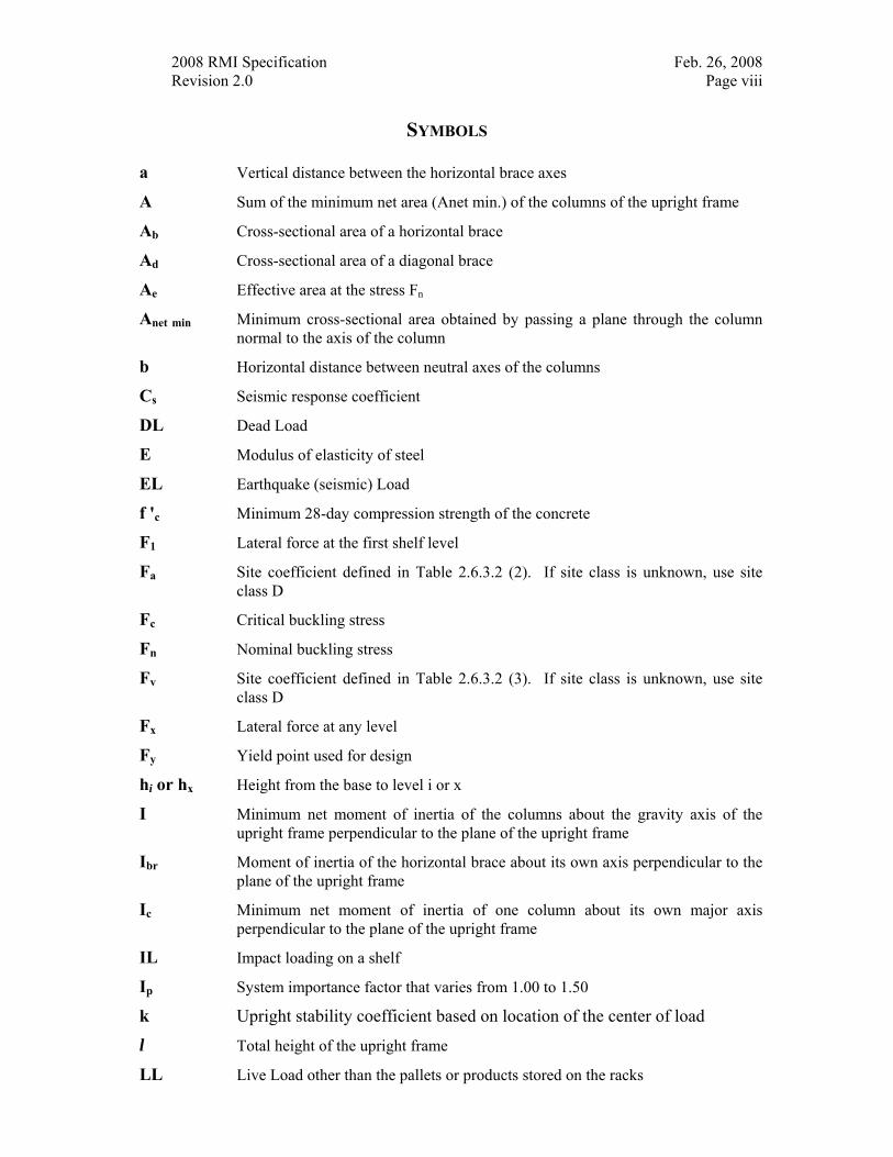
SYMBOLS a Vertical distance between the horizontal brace axes
A Sum of the minimum net area (Anet min.) of the columns of the upright frame
Ab Cross-sectional area of a horizontal brace
Ad Cross-sectional area of a diagonal brace
Ae Effective area at the stress Fn
Anet min Minimum cross-sectional area obtained by passing a plane through the column normal to the axis of the column
b Horizontal distance between neutral axes of the columns
Cs Seismic response coefficient
DL Dead Load
E Modulus of elasticity of steel
EL Earthquake (seismic) Load
f 'c Minimum 28-day compression strength of the concrete
F1 Lateral force at the first shelf level
Fa Site coefficient defined in Table 2.6.3.2 (2). If site class is unknown, use site class D
Fc Critical buckling stress
Fn Nominal buckling stress
Fv Site coefficient defined in Table 2.6.3.2 (3). If site class is unknown, use site class D
Fx Lateral force at any level
Fy Yield point used for design
hi or hx Height from the base to level i or x
I Minimum net moment of inertia of the columns about the gravity axis of the upright frame perpendicular to the plane of the upright frame
Ibr Moment of inertia of the horizontal brace about its own axis perpendicular to the plane of the upright frame
Ic Minimum net moment of inertia of one column about its own major axis perpendicular to the plane of the upright frame
IL Impact loading on a shelf
Ip System importance factor that varies from 1.00 to 1.50
k Upright stability coefficient based on location of the center of load
l Total height of the upright frame
LL Live Load other than the pallets or products stored on the racks
2008 RMI Specification Feb. 26, 2008 Revision 2.0 Page ix
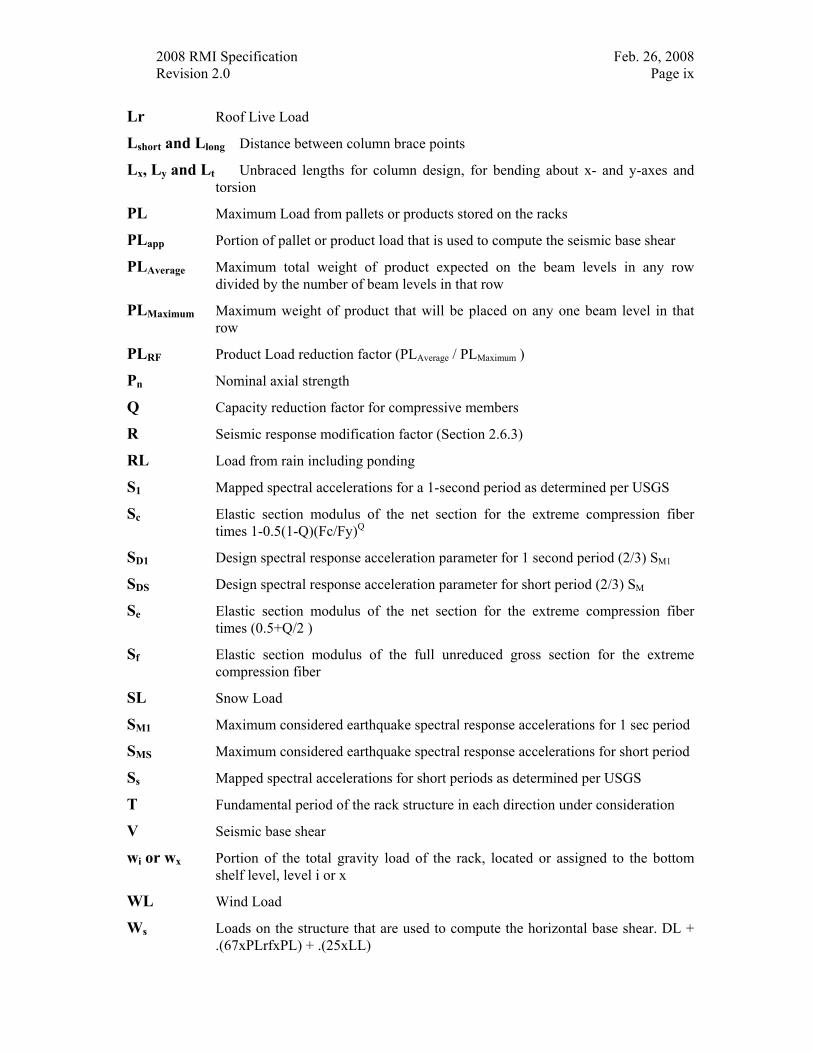
Lr Roof Live Load
Lshort and Llong Distance between column brace points
Lx, Ly and Lt Unbraced lengths for column design, for bending about x- and y-axes and torsion
PL Maximum Load from pallets or products stored on the racks
PLapp Portion of pallet or product load that is used to compute the seismic base shear
PLAverage Maximum total weight of product expected on the beam levels in any row divided by the number of beam levels in that row
PLMaximum Maximum weight of product that will be placed on any one beam level in that row
PLRF Product Load reduction factor (PLAverage / PLMaximum )
Pn Nominal axial strength
Q Capacity reduction factor for compressive members
R Seismic response modification factor (Section 2.6.3)
RL Load from rain including ponding
S1 Mapped spectral accelerations for a 1-second period as determined per USGS
Sc Elastic section modulus of the net section for the extreme compression fiber times 1-0.5(1-Q)(Fc/Fy)Q
SD1 Design spectral response acceleration parameter for 1 second period (2/3) SM1
SDS Design spectral response acceleration parameter for short period (2/3) SM
Se Elastic section modulus of the net section for the extreme compression fiber times (0.5+Q/2 )
Sf Elastic section modulus of the full unreduced gross section for the extreme compression fiber
SL Snow Load
SM1 Maximum considered earthquake spectral response accelerations for 1 sec period
SMS Maximum considered earthquake spectral response accelerations for short period
Ss Mapped spectral accelerations for short periods as determined per USGS
T Fundamental period of the rack structure in each direction under consideration
V Seismic base shear
wi or wx Portion of the total gravity load of the rack, located or assigned to the bottom shelf level, level i or x
WL Wind Load
Ws Loads on the structure that are used to compute the horizontal base shear. DL + .(67xPLrfxPL) + .(25xLL)
2008 RMI Specification Feb. 26, 2008 Revision 2.0 Page x
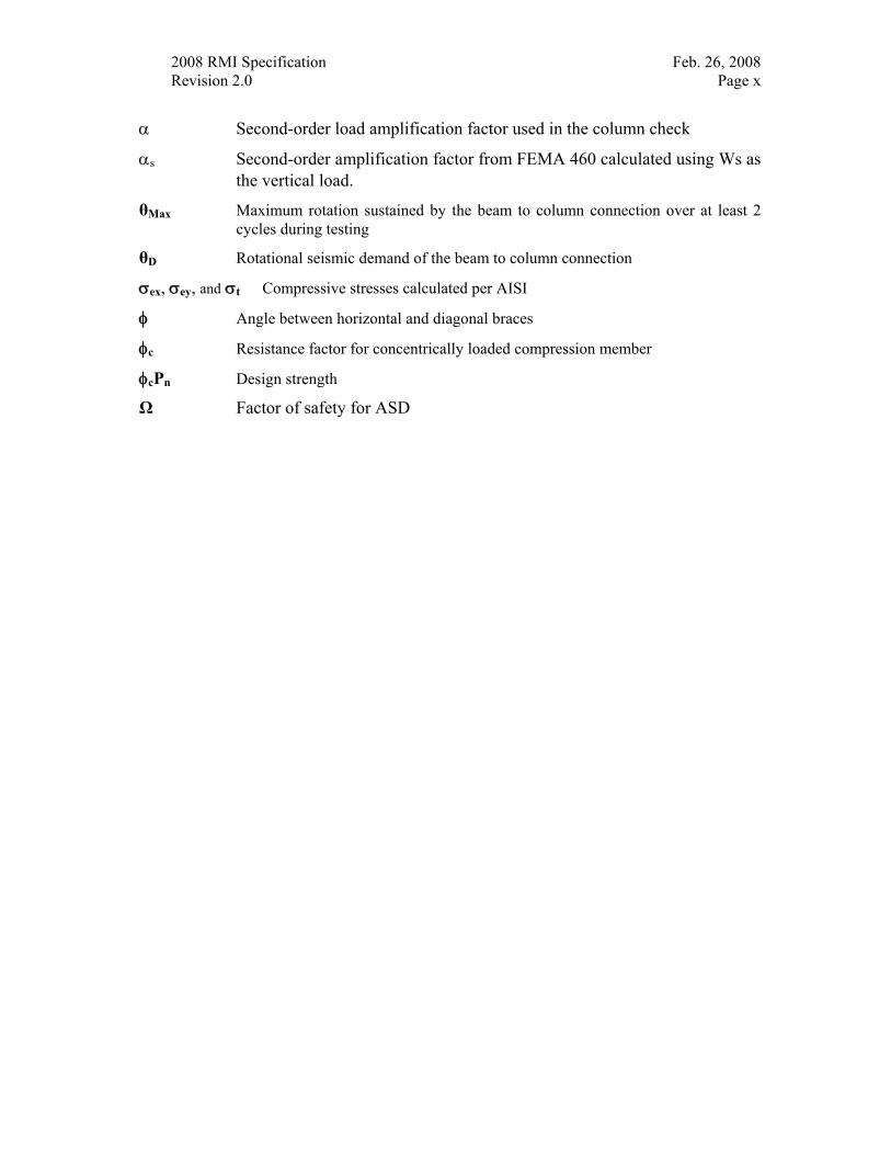
α Second-order load amplification factor used in the column check
αs Second-order amplification factor from FEMA 460 calculated using Ws as the vertical load.
θMax Maximum rotation sustained by the beam to column connection over at least 2 cycles during testing
θD Rotational seismic demand of the beam to column connection
σex, σey, and σt Compressive stresses calculated per AISI
φ Angle between horizontal and diagonal braces
φc Resistance factor for concentrically loaded compression member
φcPn Design strength
Ω Factor of safety for ASD
2008 RMI Specification Feb. 26, 2008 Revision 2.0 Page xi
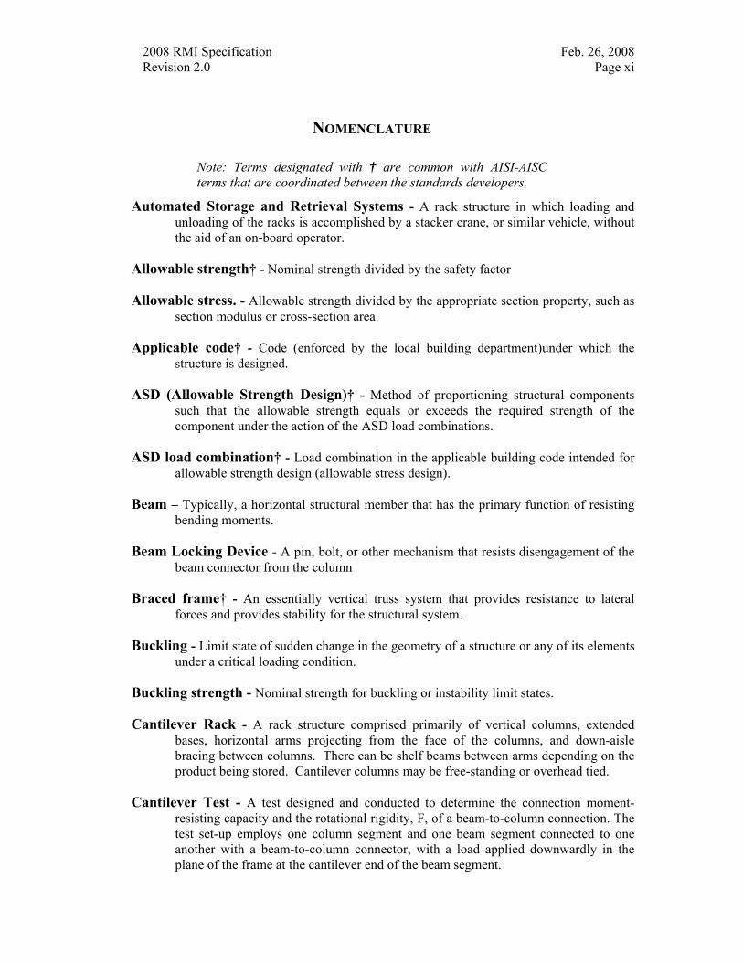
NOMENCLATURE
Note: Terms designated with † are common with AISI-AISC terms that are coordinated between the standards developers.
Automated Storage and Retrieval Systems - A rack structure in which loading and unloading of the racks is accomplished by a stacker crane, or similar vehicle, without the aid of an on-board operator.
Allowable strength† - Nominal strength divided by the safety factor
Allowable stress. - Allowable strength divided by the appropriate section property, such as section modulus or cross-section area.
Applicable code† - Code (enforced by the local building department)under which the structure is designed.
ASD (Allowable Strength Design)† - Method of proportioning structural components such that the allowable strength equals or exceeds the required strength of the component under the action of the ASD load combinations.
ASD load combination† - Load combination in the applicable building code intended for allowable strength design (allowable stress design).
Beam – Typically, a horizontal structural member that has the primary function of resisting bending moments.
Beam Locking Device - A pin, bolt, or other mechanism that resists disengagement of the beam connector from the column
Braced frame† - An essentially vertical truss system that provides resistance to lateral forces and provides stability for the structural system.
Buckling - Limit state of sudden change in the geometry of a structure or any of its elements under a critical loading condition.
Buckling strength - Nominal strength for buckling or instability limit states.
Cantilever Rack - A rack structure comprised primarily of vertical columns, extended bases, horizontal arms projecting from the face of the columns, and down-aisle bracing between columns. There can be shelf beams between arms depending on the product being stored. Cantilever columns may be free-standing or overhead tied.
Cantilever Test - A test designed and conducted to determine the connection moment-resisting capacity and the rotational rigidity, F, of a beam-to-column connection. The test set-up employs one column segment and one beam segment connected to one another with a beam-to-column connector, with a load applied downwardly in the plane of the frame at the cantilever end of the beam segment.
2008 RMI Specification Feb. 26, 2008 Revision 2.0 Page xii
Case flow rack - A specialized pallet rack structure in which either the horizontal shelf beams support case-flow lanes or case-flow shelf assemblies are supported by the upright frames. The case-flow lanes or shelves are installed at a slight pitch permitting multiple-depth case or box storage with loading from one service aisle and unloading or picking from another service aisle.
Cladding - Exterior covering of structure.
Cold-formed steel structural member† - Shape manufactured by press-braking blanks sheared from sheets, cut lengths of coils or plates, or by roll forming cold- or hot-rolled coils or sheets; both forming operations being performed at ambient room temperature; that is, without manifest addition of heat such as would be required for hot forming.
Column - Structural member that has the primary function of resisting axial force.
Concrete crushing - Limit state of compressive failure in concrete having reached the ultimate strain.
Concurrent forces - Two or more forces acting in conjunction with one another at a single location.
Connection† - Combination of structural elements and joints used to transmit forces between two or more members.
Cyclic tests - A test designed and conducted to determine the connection moment-resisting capacity and rotational rigidity, along with energy-dissipation properties, of beam-to-column connections when those connections are subjected to cyclic loading conditions. The test set-up employs one column segment and two beam segments connected to one another, using two beam-to-column connectors, as a double cantilever. Two parallel loads are applied, in opposing reversing cyclic fashion, in the plane of the frame at the ends of, and normal to, the cantilevered beam elements.
Design load† - Applied load determined in accordance with either LRFD load combinations or ASD load combinations, whichever is applicable.
Design strength† - Resistance factor multiplied by the nominal strength, [F Rn]
Design stress - Design strength divided by the appropriate section property, such as section modulus or cross section area.
Diagonal bracing - Inclined structural member carrying primarily axial force in a braced frame.
Distortional Buckling. - A mode of buckling involving change in cross-sectional shape, excluding local buckling.
Double-stacking - When a shelf is loaded with loads stacked one on top of another in a pallet position.
2008 RMI Specification Feb. 26, 2008 Revision 2.0 Page xiii
Drive-in rack - A rack structure comprised primarily of vertical upright frames, horizontal support arms, and horizontal load rails typically used for one-wide by multiple-depth storage. This structure includes an 'anchor section' with horizontal beams supporting the load rails. Loading and unloading within a bay must be done from the same aisle. A two-way drive-in rack is a special case where back-to-back rows of drive-in racks are combined into a single entity with a common rear post.
Drive-through rack - A rack structure comprised primarily of vertical upright frames, horizontal support arms, and horizontal load rails typically used for one-wide by multiple-depth storage. This structure lacks the 'anchor section' found in drive-in racks; therefore, loading and unloading from can be accomplished from both ends of a bay.
Effective length - Length of an otherwise identical column with the same strength when analyzed with pinned end conditions.
Effective length factor - Ratio between the effective length and the unbraced length of the member.
Effective section modulus - Section modulus reduced to account for buckling of slender compression elements.
Effective width - Reduced width of a plate or slab with an assumed uniform stress distribution which produces the same effect on the behavior of a structural member as the actual plate or slab width with its nonuniform stress distribution.
Factored load† - Product of a load factor and the nominal load.
Flexural buckling - Buckling mode in which a compression member deflects laterally without twist or change in cross-sectional shape.
Flexural-torsional buckling† - Buckling mode in which a compression member bends and twists simultaneously without change in cross-sectional shape.
Force - Resultant of distribution of stress over a prescribed area.
Gravity load - Load such as that produced by dead and live loads, acting in the downward direction
Kick-plate - A vertical plate (angle or barrier) that is installed at the edge of an elevated floor that is intended to prevent loose items from sliding off the edge of the floor. (Section 8.4.3.3)
Load factor† - Factor that accounts for deviations of the nominal load from the actual load, for uncertainties in the analysis that transforms the load into a load effect and for the probability that more than one extreme load will occur simultaneously.
Local buckling - Limit state of buckling of a compression element within a cross section.
2008 RMI Specification Feb. 26, 2008 Revision 2.0 Page xiv
LRFD (Load and Resistance Factor Design)† - Method of proportioning structural components such that the design strength equals or exceeds the required strength of the component under the action of the LRFD load combinations.
LRFD load combination† - Load combination in the applicable building code intended for strength design (load and resistance factor design).
Movable-shelf rack - A rack structure comprised primarily of vertical upright frames and horizontal shelf beams and typically used for one-deep pallet or hand-stack storage. Typically, the locations of a couple of shelf levels are 'fixed' with the location of the in-fill shelves being flexible.
Net area - Gross area reduced to account for removed material.
Nominal strength† - Strength of a structure or component (without the resistance factor or safety factor applied) to resist load effects, as determined in accordance with this Specification.
Out-of-plumb ratio - Maximum horizontal distance (in.) from the centerline of the column at the floor to a plumb line that extends downward from the centerline of the column at the top shelf elevation divided by the vertical distance (ft.) from the floor to the top shelf elevation.
Out-of-straight ratio – Maximum horizontal distance (in.) from the centerline at any point on the column to a plumb line from any other point on the column divided by the vertical distance (ft.) between the two points.
Overturning moment - An applied force that causes a structure to turn over
Pallet Beam - The front and back shelf members that bear the weight of the load and transfer the load to the upright frames
Pallet flow rack - A specialized pallet rack structure in which the horizontal shelf beams support pallet-flow lanes. The pallet-flow lanes are typically installed on a slight pitch permitting multiple-depth pallet storage with loading from one service aisle and unloading from another service aisle.
Pallet load support member - Any load bearing member with the long axis on the horizontal plane and intended for use as support of unit loads in direct contact. (pallet and shelf supports and beams, not bracing).
Pallet rack - A rack structure comprised primarily of vertical upright frames and horizontal shelf beams and typically used for one and two-deep pallet storage.
Pick modules - A rack structure comprised primarily of vertical frames and horizontal beams typically having one or more platform levels of selective, case-flow, or pallet-flow bays feeding into a central pick aisle(s) [work platform(s)] supported by the rack structure.
Plaque – Signage permanently and prominently displayed depicting the permissible loading of the rack
2008 RMI Specification Feb. 26, 2008 Revision 2.0 Page xv
Portable rack (stacking frames) - An assembly, typically with four corner columns, that permits stacking of one assembly on top of another without applying any additional load to the product being stored on each assembly.
Portal test - A test designed and conducted to determine the connection moment-resisting capacity and the rotational rigidity, F, of a beam-to-column connection. The test set-up employs two column segments and one beam segment connected to one another using two beam-to-column connectors forming a portal frame, with the load applied laterally in the plane of, and to the corner of, the portal frame in the direction parallel to the beam segment.
Product load - The weight of the item(s) placed on the rack
Push-back rack - A specialized pallet rack structure in which the horizontal shelf beams support push-back lanes comprised of tracks and carts. The push-back lanes are installed on a slight pitch permitting multiple-depth pallet storage. Loading and unloading are done from the same service aisle by pushing the pallets back.
Rack supported platforms - A decked working surface supported by a rack structure.
Rack supported structure - A rack structure similar to other rack structures; however, this structure also includes wall girts and roof purlins or equivalent components used to support wall and roof cladding. This structure is designed to carry, wind, snow, and rain loads in addition to the normal storage rack loads
Resistance factor† - Factor that accounts for unavoidable deviations of the nominal strength from the actual strength and for the manner and consequences of failure.
Safety factor† - Factor that accounts for deviations of the actual strength from the nominal strength, deviations of the actual load from the nominal load, uncertainties in the analysis that transforms the load into a load effect, and for the manner and consequences of failure. The nominal load divided by the safety factor results in the allowable load for an Allowable Strength Design.
Safety Flooring - A surface that is provided in areas where order picking personnel may need to step off the normal walking area or pick module walkway to dislodge loads that may not have properly flowed to their correct position.
Seismic response modification coefficient - Factor that reduces seismic load effects to strength level.
Sidesway buckling - Limit state of lateral buckling of the tension flange opposite the location of a concentrated compression force.
Simple lip – Single plate elements used to stiffen a compression flange
Site class definition - A classification assigned to a location based on the types of soils present
2008 RMI Specification Feb. 26, 2008 Revision 2.0 Page xvi
Stability - Condition reached in the loading of a structural component, frame or structure in which a slight disturbance in the loads or geometry does not produce large displacements.
Stacking rack – See Portable rack
Stacker rack - A rack structure similar to one of the other rack structures; that is serviced by an automated storage and retrieval machine.
Stiffness - Resistance to deformation of a member or structure, measured by the ratio of the applied force (or moment) to the corresponding displacement (or rotation).
Stress - Force per unit area caused by axial force, moment, shear or torsion.
Structural system - An assemblage of load-carrying components that are joined together to provide interaction or interdependence.
Stub column test – Concentric compression testing of members not affected by column buckling used to determine the column effectiveness.
Torsional buckling - Buckling mode in which a compression member twists about its shear center axis.
Torsional-Flexural Buckling. - Buckling mode in which compression members bend and twist simultaneously without change in cross section shape.
Trussed-Braced Upright Frame – Upright frames having two columns similar to the chords of a truss and diagonal and horizontal bracing attached to and located between the columns. The diagonals and horizontals become the web members of the truss. (It is referred to as a vertical truss.).
Unbraced length - Distance between braced points of a member, measured between the centers of gravity of the bracing members.
Unit Load - The total weight expected to be positioned in the rack consisting of the product load and pallet weight
Upright frame – The main members that carry the vertical and horizontal loads to the floor. They are usually made up of two columns and bracing members between the columns. The beams of the rack are attached to the columns of the frames and carry the loads to the columns.
Vertical impact load - Additional downward force added to the beams produced during loading of the rack.

2008 RMI Specification Feb. 26, 2008 Revision 2.0 Page xvii
Yield point† - First stress in a material at which an increase in strain occurs without an increase in stress as defined by ASTM.
Yield strength† - Stress at which a material exhibits a specified limiting deviation from the proportionality of stress to strain as defined by ASTM
2008 RMI Specification Feb. 26, 2008 Revision 2.0 Page 1
SPECIFICATION FOR THE DESIGN, TESTING AND UTILIZATION OF INDUSTRIAL STEEL STORAGE RACKS
2008 EDITION
1. GENERAL
1.1 SCOPE. This Specification and companion Commentary (hereinafter referred to as the Specification) applies to industrial pallet racks, movable shelf racks, rack supported systems and stacker racks made of cold-formed or hot-rolled steel structural members. Such rack types also include push back rack, pallet flow rack, case flow rack pick modules and rack supported platforms. This Specification is intended to be applied to the design of the storage rack portion of any rack structure that acts as support for the exterior walls and roof, except as noted. It does not apply to other types of racks, such as drive-in or drive-through racks, cantilever racks, portable racks, or to racks made of material other than steel.
1.2 MATERIALS. This Specification assumes the use of steel of structural quality as defined in general by the specifications of the American Society for Testing and Materials (ASTM) that are listed in the American Iron and Steel Institute (AISI) North American Specification for the Design of Cold-Formed Steel Structural Members [1]1, and the American Institute of Steel Construction (AISC) Specification for Structural Steel Buildings [2].
Steels not listed in the above specifications are not excluded provided they conform to the chemical and mechanical requirements of either reference [1] or [2], or other published specifications which establish their properties and structural suitability, and provided they are subjected either by the producer or the purchaser to analyses, tests, and other controls in the manner prescribed by either reference [1] or [2] as applicable.
1.3 APPLICABLE DESIGN SPECIFICATIONS. Except as modified or supplemented in this Specification, the AISI (2001) [1] and the AISC (2005) [2], as respectively applicable, are used in the determination of the available strength of industrial steel storage racks.
1.4 INTEGRITY OF RACK INSTALLATIONS.
1.4.1 Owner Maintenance The owner shall maintain the structural integrity of the installed rack system by assuring proper operational, housekeeping, and maintenance procedures including, but not limited to, the following:
(1) Prohibit any overloading of any pallet positions and of the overall rack system.
1 Numbers in brackets refer to corresponding numbers in Section 10, References to the Text.
2008 RMI Specification Feb. 26, 2008 Revision 2.0 Page 2
(2) Regularly inspect for damage. If damage is found, immediately unload the affected area and replace or repair any damaged columns, beams, or other structural components.
(3) Require all pallets to be maintained in good, safe, operating condition.
(4) Ensure that pallets are properly placed onto pallet load support members in a properly stacked and stable position.
(5) Require that all goods stored on each pallet be properly stacked and stable.
(6) Prohibit double-stacking of any pallet position, including the top-most position, unless the rack system is specifically designed for such loading.
(7) Ensure that the racks are not modified or rearranged in a manner not within the original design configurations per 1.4.5.
1.4.2 Plaque The owner is responsible for displaying in one or more conspicuous locations a permanent plaque(s) Each plaque shall have an area of not less than 50 square inches. Plaques shall show in clear, legible print (a) the maximum permissible unit load and/or maximum uniformly distributed load per level, (b) the average unit load (PLAverage, see Section 2.6.2) if applicable and (c) maximum total load per bay. The unit load is usually a single pallet or container and its contents mechanically transported. Storage levels having multiple stacking of unit loads shall be so identified. It is the responsibility of the owner to ensure that the rack system is not altered so that the plaque information is invalidated.
1.4.3 Conformance All rack installations produced in conformity with this Specification shall be so identified by a plaque having the same characteristics as specified in Section 1.4.2. The same plaque may be used to show permissible unit loads.
1.4.4 Load Application and Rack Configuration Drawings Load application and rack configuration drawings shall be furnished with each rack installation. One copy should be retained by the owner and another by the dealer or other local rack manufacturer representative for use by an inspecting body.
1.4.5 Multiple Configurations If a pallet rack or stacker rack system is permitted in more than one shelf configuration or profile, the drawings (Section 1.4.4) are to include either (a) all the permissible configurations or (b) limitations as to the maximum number of shelves, the maximum distance between shelves and the maximum distance from the floor to the bottom shelf. This information is best furnished in table form on the drawings. A notice is to be included in conspicuous text on the drawings stating that deviations from the limitations may impair the safety of the rack installation.
2008 RMI Specification Feb. 26, 2008 Revision 2.0 Page 3
1.4.6 Movable-Shelf Rack Stability The stability of movable shelf racks is not to depend on the presence, absence or location of the movable-shelves. Those components which do provide stability, such as the permanently bolted or welded top shelves and the longitudinal and transverse diagonal bracing, are to be clearly indicated on the rack drawings (Section 1.4.4). For specific movable-shelf rack installations in which the overall rack height it is a controlling element, a conspicuous warning is to be placed in the owners’ utilization instruction manual stating any restrictions to shelf placement or shelf removal. Such restrictions also are to be permanently posted in locations clearly visible to forklift operators.
1.4.7 Column Base Plates and Anchors The bottom of all columns shall be furnished with column base plates, as specified in Section 7.2. All rack columns shall be anchored to the floor with anchor bolts capable of resisting the forces caused by the horizontal and vertical loads on the rack.
1.4.8 Small Installations For installations not exceeding 12 feet (3.65 m) in height to the top shelf, covering a floor area less than 3,000 square feet (278.7 m2) (not including aisles), and having a unit load not exceeding 2,500 pounds (1134 kg) and having no multiple stacking on top shelf, the provisions given in Sections 1.4.4 and 1.4.5 may be waived.
1.4.9 Rack Damage Preventing damage to rack is beyond the scope of this specification. See the Commentary for a broader discussion of this topic.
Upon any visible damage, the pertinent portions of the rack shall be unloaded immediately by the user until the damaged portion is repaired or replaced.
1.4.10 Racks Connected to the Building Structure If the racks are connected to the building structure, then the location and magnitude of the maximum possible horizontal and vertical forces (per Sections 2.1 and 2.2 of this Specification) that are imposed by the rack to the building are to be given to the owner of the building for his review.
1.4.11 Out-of-plumb and Out-of-straight Limits
1.4.11.1 Out-of-plumb Limit The maximum top to bottom out-of-plumb ratio for a loaded rack column is 1/240 (for example 1/2” per 10 feet (12.5 mm per 3 m) of height). Columns whose out-of-plumb ratio exceeds this limit should be unloaded and re-plumbed. Any damaged parts must be repaired or replaced.
Top to bottom out-of-plumb ratio – maximum horizontal distance (in.) from the centerline of the column at the floor to a plumb line that extends downward from the centerline of the column at the top shelf elevation divided by the vertical distance (ft.) from the floor to the top shelf elevation.
2008 RMI Specification Feb. 26, 2008 Revision 2.0 Page 4
1.4.11.2 Out-of-straight Limit The maximum out-of-straight ratio for a loaded rack column is 1/240 (0.05” per foot or 1/2” per 10 feet (12.5 mm per 3 m) of height). Columns whose out-of-straight ratio exceeds this limit should be unloaded and re-plumbed. Any damaged parts must be repaired or replaced.
Out-of-straight ratio – maximum horizontal distance (in.) from the centerline at any point on the column to a plumb line from any other point on the column divided by the vertical distance (ft.) between the two points.
2. LOADING
Rack structures shall be designed using the provisions for Load and Resistance Factor Design (LRFD), or the provisions for Allowable Strength Design (ASD). Both methods are equally acceptable although they may not produce identical designs.
2.1 LOAD COMBINATIONS FOR THE ASD DESIGN METHOD When the ASD design method is used, all load combinations shall be as stated in the ASCE 7 [5] as modified below for racks.
For all rack members Critical Limit State
1. DL Dead Load Critical 2. DL + PL + LL + (Lr or SL or RL) Gravity Load Critical 3. 0.6DL + 0.6PLapp - WL Wind Uplift Critical
(0.6 - 0.11Sds)DL + (0.6 - 0.14Sds)PLapp-EL Seismic Uplift Critical 4. DL + PL + LL + (Lr or SL or RL) + WL Gravity Plus Wind/Seismic
Critical (1 + 0.11SDS)DL + (1 + 0.14SDS)PL + LL + (Lr or SL or RL) +EL Gravity – Seismic Critical
For load support beams and their connections only: 5. DL + LL+ 0.5(SL or RL) + 0.88PL+ IL Shelf Plus Impact Critical
where: DL = Dead Load LL = Live Load other than the pallets or products stored on the racks.
( Example, floor loading from rack supported platforms) Lr = Roof Live Load SL = Snow Load RL = Load from rain including ponding WL = Wind Load EL = Seismic Load IL = Impact loading on a shelf (Section 2.3) PL = Maximum Load from pallets or products stored on the racks. PLapp = When checking for seismic uplift, the portion of pallet or product
load that is used to compute the seismic base shear. When checking for wind uplift, if loads must be present, to develop calculated wind force, their minimum weight may be included in PLapp. See Commentary.
2008 RMI Specification Feb. 26, 2008 Revision 2.0 Page 5
When checking for uplift due to wind, PLapp is equal to the minimum weight of the loads that must be present to develop the calculated lateral wind force. See Commentary
All loads in Cases 3 and 4 except the Dead Load may be multiplied by 0.75. In addition to the 0.75 multiplier, for Cases 3 and 4 the seismic force (EL) determined in accordance with Section 2.6 or another limit-states based code may be multiplied by 0.67 because the limit states based codes give higher seismic forces.
2.2 LOAD FACTORS AND COMBINATIONS FOR THE LRFD DESIGN METHOD When the LRFD design method is used, all load factors and combinations shall be as stated in the ASCE 7 [5] except as modified below for racks:
For all rack members: Critical Limit State
1. 1.4DL + 1.2PL Dead load 2. 1.2DL + 1.4PL + 1.6LL + 0.5(Lr or SL or RL) Live/Product load 3. 1.2DL + 0.85PL + (0.5LL or 0.8WL) + 1.6(Lr or SL or RL) Snow/Rain 4. 1.2DL + 0.85PL + 0.5LL + 1.6WL + 0.5(Lr or SL or RL) Wind load 5. (1.2 + 0.2SDS)DL + (0.85 + 0.2SDS)PL + 0.5LL + 1.5EL + 0.2SL Seismic
load 6. 0.9DL + 0.9PLapp – 1.6WL Wind Uplift
(0.9 – 0.2SDS)DL+ (0.9 – 0.2SDS)PLapp – 1.5EL Seismic Uplift
For load support beams and their connections only: 7. 1.2DL + 1.6LL+ 0.5(SL or RL) + 1.4PL + 1.4 * IL Product/Live/Impact
(for shelves and connections) All load symbols, DL, LL, PL, Lr, SL, RL, WL, EL and IL are as defined in Section 2.1.
Note: The load factor for EL in load cases 5 and 6 must be 1.5 unless the seismic loading is determined in accordance with Section 2.6 or another limit-states based code. If Section 2.6 or a Limit States based code is used to determine the seismic forces the load factor for EL may be 1.0 for load cases 5 and 6.
For load case 6a (wind uplift), only pallet loads that must be present to develop the lateral wind forces shall be considered in PLapp. PLapp will be zero for an unloaded rack that supports exterior cladding.
All resistance factors are to be as stated in the AISI (2001) [1] or AISC (2005) [2]. The resistance factors for anchor bolts are determined as follows:
For wind uplift: φ =0.45 For seismic: φ =0.55 For overturning forces in Section 8: φ =0.40
2.3 VERTICAL IMPACT LOADS. Load-supporting beams and arms and connector components used to attach them to the columns are to be designed for an additional vertical impact load equal to 25 per cent of one unit load. This impact load is to be placed in the most unfavorable position when determining maximum load on each component. For beams or arms whose design capacity is determined by testing (Section 9.3), due allowance must be made for the additional impact load. This impact load need not be applied when checking beam deflections (Sections 5.3 and 9.3) or designing upright frames, columns, and other vertical components.
2008 RMI Specification Feb. 26, 2008 Revision 2.0 Page 6
2.4 Horizontal Forces.
2.4.1 Beam-to-column connections, frame bracing members, and frame bracing to column connections are to be designed for the horizontal forces in this section.
The amount of horizontal force that a rack must resist varies with the application. The beam-to-column connections and frame bracing members and frame bracing connections must be designed for the most critical of:
1. Earthquake Loads (Section 2.6).
2. Wind Forces (Section 2.5)
3. For Allowable Strength Design -1.5%DL plus 1.5%PL at all connections based on maximum loading. For Load and Resistance Factor Design - 1.5% factored DL plus 1.5% factored PL based on the maximum loading.
These horizontal forces include the effect of out-of-plumbness (Section 1.4.11). These forces are to be applied separately, not simultaneously, in each of the two principal directions of the rack.
The horizontal forces are to be applied simultaneously with the full vertical live load, product load and dead load. Bending loads at the beam-to-column connection shall be checked against the permissible moments (both positive and negative) determined from the Cantilever Test (Section 9.4.1) and/or the Portal Test (Section 9.4.2).
2.4.2. Stacker racks or racks fully or partially supporting moving equipment shall meet the requirements of Sections 2.4.2.1, 2.4.2.2 and 2.6.
2.4.2.1. The moving equipment manufacturer is responsible for supplying to the rack manufacturer the magnitude, location, and direction of all loads (static and dynamic) transmitted from the moving equipment to the rack structure.
2.4.2.2. Forces described in Section 2.4.2.1 need not be applied concurrently with the loads described in Sections 2.5 and 2.6.
2.5 WIND LOADS. Wind forces shall be determined in accordance with ASCE 7 [5].
Racks directly exposed to the wind shall be designed for the wind loads acting both on the rack structure and the loaded pallets. For stability, consideration is to be given to loading conditions which produce large wind forces combined with small stabilizing gravity forces.
The forces described in Section 2.4.1, except for that portion of horizontal loading resulting from an out-of-plumb installation, and Section 2.6 need not be assumed to act concurrently with wind loads. The forces described in Section 2.4.2 shall not be assumed to act concurrently with wind forces.
2008 RMI Specification Feb. 26, 2008 Revision 2.0 Page 7
2.6 EARTHQUAKE LOADS
2.6.1 General Where customer specifications require or local building codes dictate that provisions be made for earthquake effects and associated lateral forces, customers or their representatives shall bring such requirements to the attention of the rack manufacturer. For each such installation, the storage rack shall be designed, manufactured, and installed in accordance with such provisions. Storage racks that are more than 8 ft (2.44 m) in height to the top load shelf and are not connected to buildings or other structures, shall be designed to resist seismic forces in conformance with this section.
Adequate clearance shall be maintained between the storage rack and the building or other structures to avoid damaging contact during an earthquake.
Unless used to store hazardous material, storage racks are to be deemed Occupancy Category II structures.
2.6.2 Minimum Seismic Forces The storage rack shall be designed for the total minimum lateral force as determined using the following considerations or, alternatively the seismic design evaluation may be performed using a displacement-based method, such as the method described in Section 6.5.1 of FEMA 460 [4].
At-Grade Elevation: Storage rack installed at or below grade elevation shall be designed, fabricated and installed in accordance with the following requirements:
The seismic design forces shall not be less than that required by the following equation for the determination of seismic base shear:
V C I Ws p s=
where:
Cs = the seismic response coefficient determined in Section 2.6.3.
Ip = system importance factor: Ip = 1.5 if the system is an essential facility; Ip = 1.5 if the system contains material that would be significantly
hazardous if released; Ip = 1.0 for all other structures;
For storage rack in areas open to the public, (e.g., in warehouse retail stores), Ip = 1.5. If a displacement based evaluation of the rack structure is performed in either of the two principle directions of the rack, Ip may be taken as 1.0 in that direction.
Ws = ( )0 67 0 25. .xPL xPL DL xLLRF + +
where:
2008 RMI Specification Feb. 26, 2008 Revision 2.0 Page 8
PLRF = Product Load Reduction Factor
Seismic Force Direction PLRF
Cross-Aisle 1.0
Down-Aisle PLPL
Average
Maximum
PLAverage For warehouse retail stores, open to the general public, PLAverage shall be taken as PLMaximum.
For all other types of warehousing PLAverage is the maximum total weight of product expected on all the beam levels in any row divided by the number of beam levels in that row.
PLMaximum Maximum weight of product that will be placed on any one beam level in that row.
Above-Grade Elevation: Storage rack installed at elevations above grade shall be designed, fabricated and installed in accordance with the following requirements:
Storage racks shall meet the force and displacement requirements required of nonbuilding structures supported by other structures, including the force and displacement effects caused by amplifications of upper-story motions.
As above, Ws = ( )0 67 0 25. .xPL xPL DL xLLRF + +
2.6.3 Calculation of Seismic Response Coefficient When the fundamental period of the rack structure is computed, the seismic response coefficient, Cs, shall be determined in accordance with the following equation:
TRSC D
s1=
where:
SD1 = Design earthquake spectral response acceleration at a 1 second period, as described in Section 2.6.3.1.
R = Response modification factor R = 4.0 in the braced direction and R = 6.0 in the unbraced direction. Higher values may be used if substantiated by tests.
T = Fundamental period of the rack structure in each direction under consideration established using the structural properties and deformation characteristics of the resisting elements in a properly substantiated analysis. For the unbraced direction (moment frame), the period shall be determined
2008 RMI Specification Feb. 26, 2008 Revision 2.0 Page 9
using a connection stiffness, F not less than the value from Section 9.4.2.3 or Section 9.6.
Alternatively, the seismic response coefficient need not be greater than the following:
RSC DS
s =
where:
R is as above
SDS = Design earthquake spectral response acceleration at short periods, as described in Section 2.6.3.1.
The seismic response coefficient, CS, shall not be taken as less than 0.044SDS
Additionally, in locations for which the 1-second spectral response, S1, is equal to or greater than 0.6g, the value of the seismic response coefficient, Cs shall not be taken as less than:
RS.Cs
150=
2.6.3.1 Design Spectral Response Acceleration Parameters Five-percent damped design spectral response acceleration at short periods, SDS, and at a 1-second period, SD1, shall be determined from the following equations:
SDS = (2/3) SMS
SD1 = (2/3) SM1
where:
SMS = The maximum considered earthquake spectral response accelerations for short period as determined in Section 2.6.3.2.
SM1 = The maximum considered earthquake spectral response accelerations for 1 sec period as determined in Section 2.6.3.2.
2.6.3.2 Site Coefficients and Adjusted Maximum Considered Earthquake Spectral Response Acceleration Parameters
The maximum considered earthquake spectral response acceleration for short periods, SMS, and at 1-second period, SM1, adjusted for site class effects, shall be determined from the following equations:
SMS = FaSS
SM1 = Fv S1
where:
Fa = Site coefficient defined in Table 2.6.3.2 (2). If site class is unknown, use site class D
2008 RMI Specification Feb. 26, 2008 Revision 2.0 Page 10
Fv = Site coefficient defined in Table 2.6.3.2 (3). If site class is unknown, use site class D
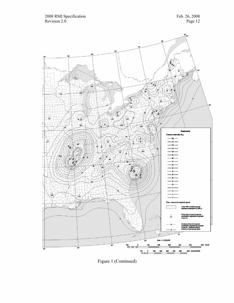
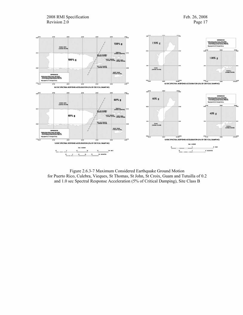
Ss = The mapped spectral accelerations for short periods as determined per USGS Open-File Report 01-437 “Earthquake Spectral Response Acceleration Maps” Version 3.10 values based on zip codes or longitude and latitude of site or Figure 1, 3, 5, or 7. Where zip codes are used to determine spectral accelerations, the largest value of any location within the zip code shall be used.
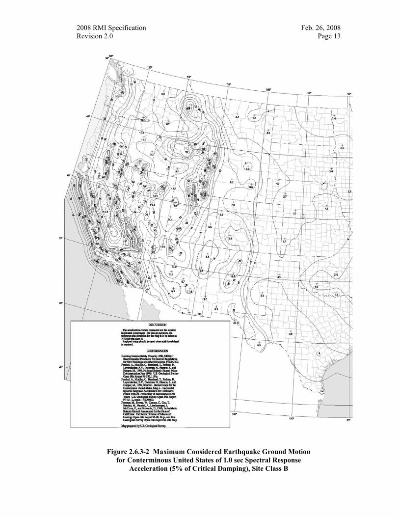
S1 = The mapped spectral accelerations for a 1-second period as determined per USGS Open-File Report 01-437 “Earthquake Spectral Response Acceleration Maps” Version 3.10 values based on zip codes or longitude and latitude of site or Figure 2, 4, 6, or 7. Where zip codes are used to determine spectral accelerations, the largest value of any location within the zip code shall be used.

2008 RMI Specification Feb. 26, 2008 Revision 2.0 Page 11
Figure 2.6.3-1 Maximum Considered Earthquake Ground Motion for Conterminous United States of 0.2 sec Spectral Response
Acceleration (5% of Critical Damping), Site Class B
2008 RMI Specification Feb. 26, 2008 Revision 2.0 Page 12
Figure 1 (Continued)
2008 RMI Specification Feb. 26, 2008 Revision 2.0 Page 13
Figure 2.6.3-2 Maximum Considered Earthquake Ground Motion for Conterminous United States of 1.0 sec Spectral Response
Acceleration (5% of Critical Damping), Site Class B
2008 RMI Specification Feb. 26, 2008 Revision 2.0 Page 14
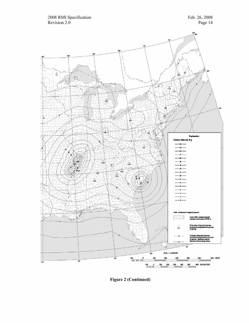
Figure 2 (Continued)
2008 RMI Specification Feb. 26, 2008 Revision 2.0 Page 15
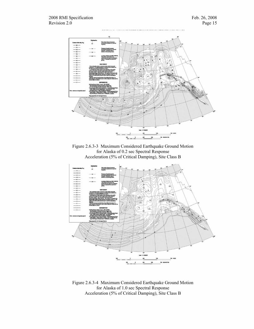
Figure 2.6.3-3 Maximum Considered Earthquake Ground Motion
for Alaska of 0.2 sec Spectral Response Acceleration (5% of Critical Damping), Site Class B
Figure 2.6.3-4 Maximum Considered Earthquake Ground Motion for Alaska of 1.0 sec Spectral Response
Acceleration (5% of Critical Damping), Site Class B
2008 RMI Specification Feb. 26, 2008 Revision 2.0 Page 16
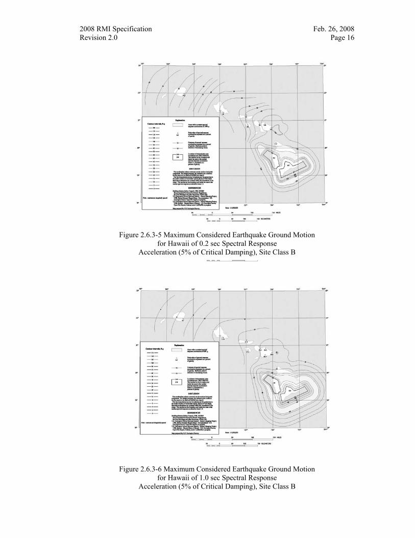
Figure 2.6.3-5 Maximum Considered Earthquake Ground Motion for Hawaii of 0.2 sec Spectral Response
Acceleration (5% of Critical Damping), Site Class B
Figure 2.6.3-6 Maximum Considered Earthquake Ground Motion
for Hawaii of 1.0 sec Spectral Response Acceleration (5% of Critical Damping), Site Class B
2008 RMI Specification Feb. 26, 2008 Revision 2.0 Page 17
Figure 2.6.3-7 Maximum Considered Earthquake Ground Motion
for Puerto Rico, Culebra, Vieques, St Thomas, St John, St Croix, Guam and Tutuilla of 0.2 and 1.0 sec Spectral Response Acceleration (5% of Critical Damping), Site Class B
2008 RMI Specification Feb. 26, 2008 Revision 2.0 Page 18
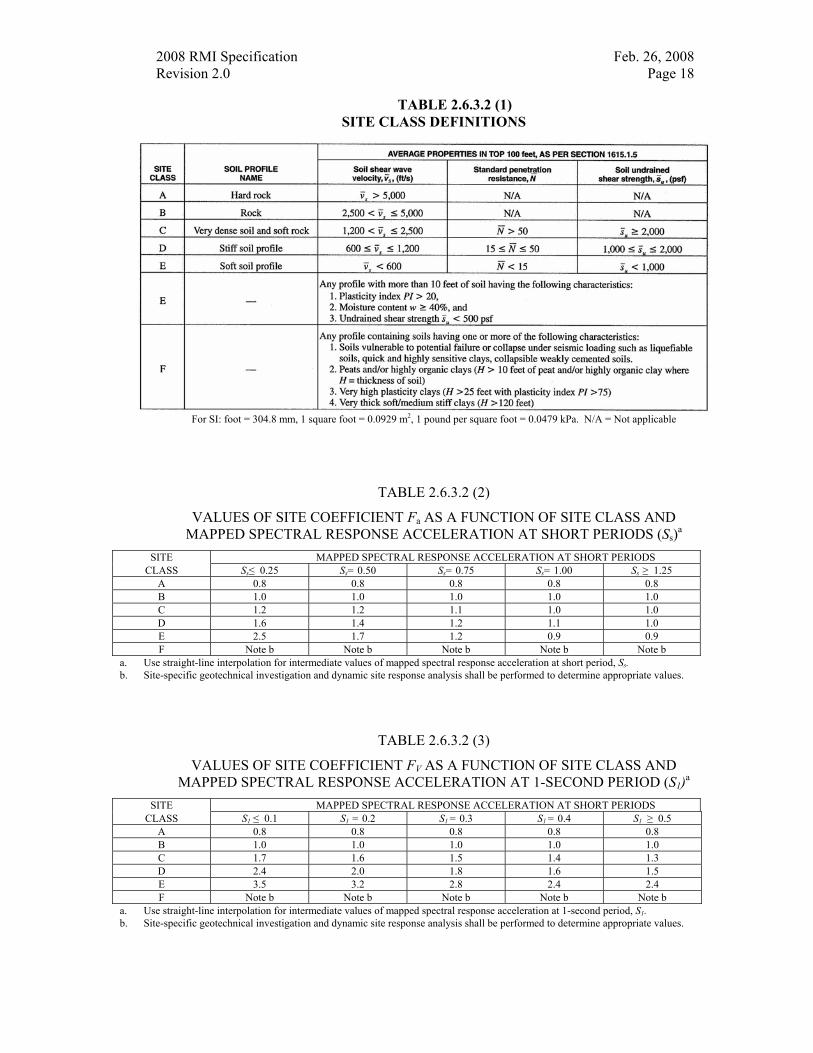
TABLE 2.6.3.2 (1) SITE CLASS DEFINITIONS
For SI: foot = 304.8 mm, 1 square foot = 0.0929 m2, 1 pound per square foot = 0.0479 kPa. N/A = Not applicable
TABLE 2.6.3.2 (2)
VALUES OF SITE COEFFICIENT Fa AS A FUNCTION OF SITE CLASS AND MAPPED SPECTRAL RESPONSE ACCELERATION AT SHORT PERIODS (Ss)a
SITE MAPPED SPECTRAL RESPONSE ACCELERATION AT SHORT PERIODS CLASS Ss≤ 0.25 Ss= 0.50 Ss= 0.75 Ss= 1.00 Ss ≥ 1.25
A 0.8 0.8 0.8 0.8 0.8 B 1.0 1.0 1.0 1.0 1.0 C 1.2 1.2 1.1 1.0 1.0 D 1.6 1.4 1.2 1.1 1.0 E 2.5 1.7 1.2 0.9 0.9 F Note b Note b Note b Note b Note b
a. Use straight-line interpolation for intermediate values of mapped spectral response acceleration at short period, Ss. b. Site-specific geotechnical investigation and dynamic site response analysis shall be performed to determine appropriate values.
TABLE 2.6.3.2 (3)
VALUES OF SITE COEFFICIENT FV AS A FUNCTION OF SITE CLASS AND MAPPED SPECTRAL RESPONSE ACCELERATION AT 1-SECOND PERIOD (S1)a
SITE MAPPED SPECTRAL RESPONSE ACCELERATION AT SHORT PERIODS CLASS S1 ≤ 0.1 S1 = 0.2 S1 = 0.3 S1 = 0.4 S1 ≥ 0.5
A 0.8 0.8 0.8 0.8 0.8 B 1.0 1.0 1.0 1.0 1.0 C 1.7 1.6 1.5 1.4 1.3 D 2.4 2.0 1.8 1.6 1.5 E 3.5 3.2 2.8 2.4 2.4 F Note b Note b Note b Note b Note b
a. Use straight-line interpolation for intermediate values of mapped spectral response acceleration at 1-second period, S1. b. Site-specific geotechnical investigation and dynamic site response analysis shall be performed to determine appropriate values.
2008 RMI Specification Feb. 26, 2008 Revision 2.0 Page 19
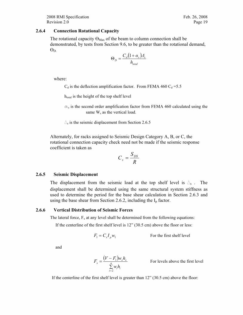
2.6.4 Connection Rotational Capacity
The rotational capacity ӨMax of the beam to column connection shall be demonstrated, by tests from Section 9.6, to be greater than the rotational demand, ӨD.
( )total
ssdD h
ΔαC +=
1Θ
where: Cd is the deflection amplification factor. From FEMA 460 Cd =5.5
htotal is the height of the top shelf level
as is the second order amplification factor from FEMA 460 calculated using the same Ws as the vertical load.
Ds is the seismic displacement from Section 2.6.5
Alternately, for racks assigned to Seismic Design Category A, B, or C, the rotational connection capacity check need not be made if the seismic response coefficient is taken as
RS
C DSs =
2.6.5 Seismic Displacement
The displacement from the seismic load at the top shelf level is Ds . The displacement shall be determined using the same structural system stiffness as used to determine the period for the base shear calculation in Section 2.6.3 and using the base shear from Section 2.6.2, including the Ip factor.
2.6.6 Vertical Distribution of Seismic Forces The lateral force, Fx at any level shall be determined from the following equations:
If the centerline of the first shelf level is 12” (30.5 cm) above the floor or less:
11 wICF ps= For the first shelf level
and
( )
∑
−=
=
n
iii
xxx
hw
hwFVF
2
1 For levels above the first level
If the centerline of the first shelf level is greater than 12” (30.5 cm) above the floor:
2008 RMI Specification Feb. 26, 2008 Revision 2.0 Page 20
∑=
= n
1iii
xxx
hw
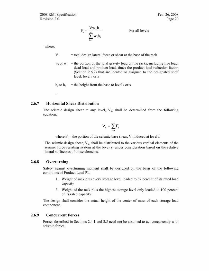
hVwF For all levels
where:
V = total design lateral force or shear at the base of the rack
wi or wx = the portion of the total gravity load on the racks, including live load, dead load and product load, times the product load reduction factor, (Section 2.6.2) that are located or assigned to the designated shelf level, level i or x
hi or hx = the height from the base to level i or x
.
2.6.7 Horizontal Shear Distribution The seismic design shear at any level, Vx, shall be determined from the following equation:
∑=
=n
xiix FV
where Fi = the portion of the seismic base shear, V, induced at level i.
The seismic design shear, Vx, shall be distributed to the various vertical elements of the seismic force resisting system at the level(s) under consideration based on the relative lateral stiffnesses of those elements.
2.6.8 Overturning Safety against overturning moment shall be designed on the basis of the following conditions of Product Load PL:
1. Weight of rack plus every storage level loaded to 67 percent of its rated load capacity
2. Weight of the rack plus the highest storage level only loaded to 100 percent of its rated capacity
The design shall consider the actual height of the center of mass of each storage load component.
2.6.9 Concurrent Forces Forces described in Sections 2.4.1 and 2.5 need not be assumed to act concurrently with seismic forces.
2008 RMI Specification Feb. 26, 2008 Revision 2.0 Page 21
3. DESIGN PROCEDURES
All computations for safe loads, stresses, deflections, and the like shall be made in accordance with conventional methods of structural design as specified in the AISI (2001) [1] for cold-formed steel components and structural systems and the AISC (2005) [2] for hot-rolled steel components and structural systems except as modified or supplemented by this specification. In cases where adequate methods of design calculations are not available, designs shall be based on test results obtained in accordance with this specification or Section F of the AISI (2001) [1].
No slenderness limitations shall be imposed on tension members that are not required to resist compression forces under the various load combinations specified in Section 2.1 or 2.2.
4. DESIGN OF STEEL ELEMENTS AND MEMBERS
The effect of perforations on the load-carrying capacity of compression members is accounted for by the modification of some of the definitions of the AISI (2001) [1] and the AISC (2005) [2] as described below.
4.1 Cold-Formed Steel Members The AISI (2001) [1] Section C
4.1.1 Properties of Sections The AISI (2001) [1] Section C1 Exceptions to the provisions of the AISI (2001) [1] for computing the section properties are given in Sections 4.1.2 and 4.1.3. Except as noted all cross-sectional properties shall be based on full unreduced and unperforated sections considering round corners.
4.1.2 Flexural Members The AISI (2001) [1] Section C3.
Se = Elastic section modulus of the net section times ( 0 52
. +Q ) for the extreme
compression fiber.
Sc = Elastic section modulus of the net section for the extreme compression fiber times
( )Q
y
c
FFQ
⎟⎟⎠
⎞⎜⎜⎝
⎛−−
211
The value of Q shall be determined according to Section 9.2.2. Section properties j, ro, and Cw shall be permitted to be computed assuming sharp corners.
Inelastic reserve capacity provisions of the AISI (2001) [1] Section C3.1.1 (b) shall not be considered for perforated members.
4.1.3 Concentrically Loaded Compression Members. The AISI (2001) [1] Section C4.
4.1.3.1 Effective Area Ae = Effective area at the stress Fn determined according to Section 4.1 when applicable. Where Section 4.1 is not applicable, Ae shall be calculated as:
2008 RMI Specification Feb. 26, 2008 Revision 2.0 Page 22
( )A QFF Ae
n
y
Q
net= − −⎛
⎝⎜⎜
⎞
⎠⎟⎟
⎡
⎣
⎢⎢
⎤
⎦
⎥⎥
1 1 min
where the Q factor shall be determined by the procedure specified in Section 9.2 and Anet min is defined in Section 9.2.
Lx, Ly and Lt are the unbraced lengths defined in Section 6.3 for bending about x- and y-axes and twisting. Torsional warping constant CW may be calculated based on sharp corners.
4.1.3.2 Distortional Buckling Open sections except those with unstiffened elements or only simple lip edge stiffeners shall be checked for the effects of distortional buckling by testing or rational analysis.
4.2 Hot-Rolled Steel Columns (AISC (2005) [2] Chapter E) All hot-rolled steel columns shall be designed according to Section E7, of the AISC (2005) [2] except as noted below.
The nominal compressive strength Pn shall be calculated as follows:
P A Fn e cr=
Ae is defined in Section 4.1.3.1 The value of Q shall be determined according to Section 9.2.2.
5. BEAMS
5.1 Calculations. The bending moments, reactions, shear forces, and deflections shall be determined by considering the beams as simply supported, or by rational analysis for beams having partial end-fixity. Where the shape of the beam cross section and the end-connection details permit, permissible loads of pallet-carrying beams shall be determined by conventional methods of calculation according to the AISI (2001) [1] or the AISC (2005) [2].
5.2 Cross Section. Where the configuration of the cross section precludes calculation of allowable loads and deflections, the determination shall be made by tests according to Section 9.
5.3 Deflections. At working load (excluding impact) the deflections shall not exceed 1/180 of the span measured with respect to the ends of the beam.
6. UPRIGHT FRAME DESIGN.
6.1 Definition. The upright-frame consists of columns and bracing members.
2008 RMI Specification Feb. 26, 2008 Revision 2.0 Page 23
6.2 General.
6.2.1 Upright-frames and multi-tiered portal frames shall be designed for the critical combinations of vertical and horizontal loads for the most unfavorable positions as specified in Section 2. All moments and forces induced in the columns by the beams shall be considered. In lieu of the calculation, frame capacity may be established by tests according to Section 9.5.
6.2.2 Connections that cannot be readily analyzed shall be capable of withstanding the moments and forces in proper combinations as shown by test.
6.3 Effective Lengths. Effective lengths for columns are those specified in Sections 6.3.1 through 6.3.4, or as determined by rational analysis or tests.
Guidance for using effective length method is given in the following subsections. It is not intended to preclude the use of other design methods. Other rational methods, consistent with AISC and AISI may be used. One column stability design method should be used consistently throughout one structure.
6.3.1 Flexural Buckling in the Direction Perpendicular to the Upright Frames. Lx is the distance from the centerline of one beam to the centerline of the next beam or the distance from the floor to the centerline of the first beam.
6.3.1.1 Racks Not Braced Against Sidesway. For the portion of the column between the bottom beam and the floor as well as between the beam levels, the effective length factor K shall be taken as 1.7 or as otherwise determined by an analysis properly accounting for the member stiffnesses, the semi-rigid nature of the beam to column connections and the partial fixity of the base, allowing for average load reduction, as applicable.
If K of 1.7 is used without analysis, then no reduction of this value shall be made.
6.3.1.2 Racks Braced Against Sidesway. The effective length factor for pallet racks, stacker racks, and movable-shelf racks is K = 1 provided that all such racks have diagonal bracing in the vertical plane and that such racks have either a rigid and fixed top shelf, or diagonal bracing in the horizontal plane of the top fixed shelf. Increased column capacity may be achieved by additional rigid and fixed shelf (or shelves) or bracing in the horizontal plane. The unsupported length is defined as the distance from floor to fixed top shelf or bracing; or, in the case of additional rigid fixed shelf (or shelves) or fixed shelf with diagonal bracing in its horizontal plane, the unsupported length is the distance between fixed shelves or between braced shelves. The effective length factor is K = 1. If there is no bracing in the vertical plane of the rack, the K values are the same as for racks in Section 6.3.1.1, Racks Not Braced Against Sidesway.
2008 RMI Specification Feb. 26, 2008 Revision 2.0 Page 24
6.3.2 Flexural Buckling in the Plane of the Upright Frame.
6.3.2.1 Ly is defined as the distance between the intersection of the neutral axis of the column with the neutral axis of either two adjacent diagonals or a diagonal and a horizontal.
6.3.2.2 For upright frames having diagonal braces or a combination of diagonal and horizontal braces that intersect the columns, the effective length factor K for the portion of the column between braced points shall be taken as 1.0, provided that the maximum value of the ratio of Lshort to Llong does not exceed 0.15.
Lshort or Llong is defined as the distance between the intersection of the neutral axis of the column with the neutral axis of either two adjacent diagonals or a diagonal and a horizontal.
In an upright frame with diagonals and horizontals, Lshort and Llong refer to the minimum and maximum distances between two adjacent segments between two adjacent horizontals. In an upright frame with only diagonal Lshort and Llong refer to two adjacent segments. All distances are measured along the neutral axis of the column.
6.3.2.3 For upright frames having diagonal braces that intersect the horizontal braces, the effective length factor K for the portion of the column between braced points shall be taken as 1.0 providing the ratio of Lshort to Llong does not exceed 0.12.
Lshort is defined as the shortest distance between the intersection of the neutral axis of one of the two diagonal braces with the neutral axis of the horizontal brace, or the shortest distance between the intersection of one diagonal brace with the neutral axis of the horizontal brace with the neutral axis of the column.
Llong is defined as the length of the horizontal brace measured between the neutral axes of the columns.
All measurements are along the neutral axis of the horizontal brace.
6.3.2.4 For upright frames having bracing patterns not included above, the effective length factor K of the column shall be determined by rational analysis or by upright frame test.
6.3.3 Torsional Buckling.
6.3.3.1 Lt is the length of the member unsupported against twisting.
6.3.3.2 The effective length factor Kt for torsional buckling shall be taken as 0.8 provided that the connection details between the columns and the braces are such that the twisting of the column is prevented at the brace points. If the connection details do not prevent twist, Kt can be larger and shall be determined by rational analysis or test.
6.3.4 Diagonals and Horizontals.
For compression diagonals and horizontal members of trussed upright frames, the effective length is the full unsupported length of the member.
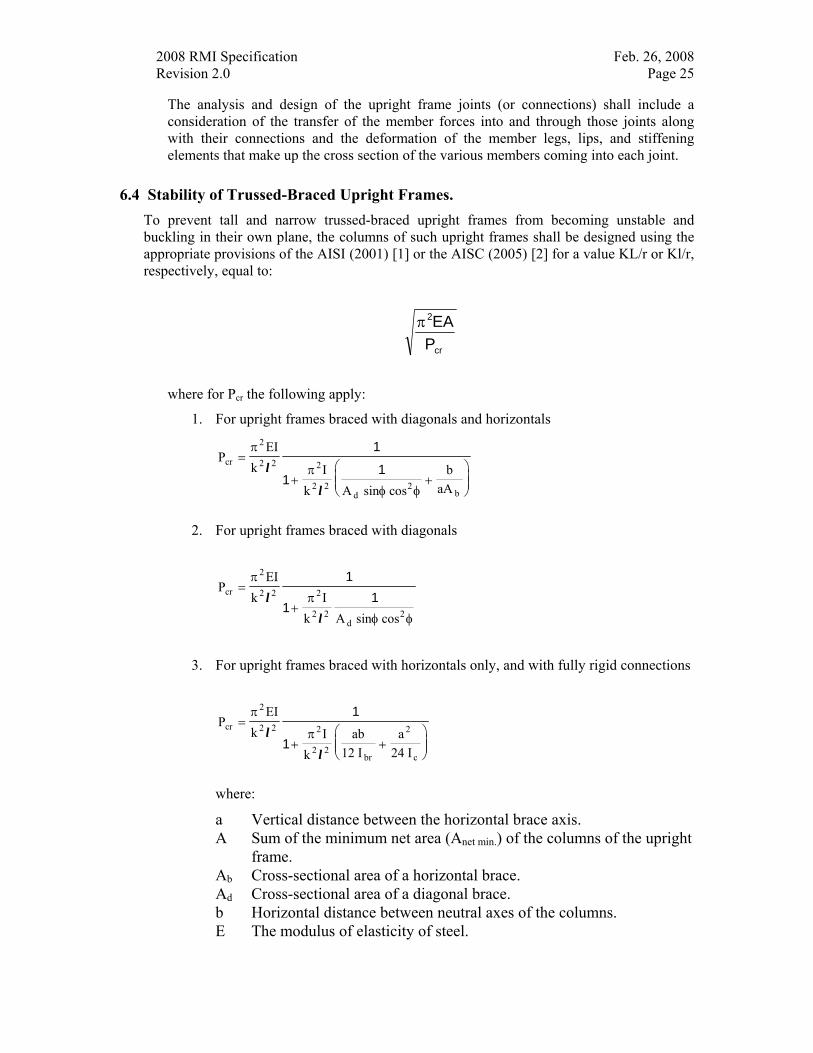
2008 RMI Specification Feb. 26, 2008 Revision 2.0 Page 25
The analysis and design of the upright frame joints (or connections) shall include a consideration of the transfer of the member forces into and through those joints along with their connections and the deformation of the member legs, lips, and stiffening elements that make up the cross section of the various members coming into each joint.
6.4 Stability of Trussed-Braced Upright Frames. To prevent tall and narrow trussed-braced upright frames from becoming unstable and buckling in their own plane, the columns of such upright frames shall be designed using the appropriate provisions of the AISI (2001) [1] or the AISC (2005) [2] for a value KL/r or Kl/r, respectively, equal to:
π2EAPcr
where for Pcr the following apply:
1. For upright frames braced with diagonals and horizontals
PEI
k Ik A sin cos
baA
cr
2
2 2 2
2 2d
2b
=
+ +⎛
⎝⎜⎜
⎞
⎠⎟⎟
π
π
φ φ
l
l
1
11
2. For upright frames braced with diagonals
PEI
k Ik A sin cos
cr
2
2 2 2
2 2d
2
=
+
π
π
φ φ
ll
1
11
3. For upright frames braced with horizontals only, and with fully rigid connections
PEI
k Ik
ab12 I
a24 I
cr
2
2 2 2
2 2br
2
c
=
+ +⎛
⎝⎜⎜
⎞
⎠⎟⎟
π
πl
l
1
1
where:
a Vertical distance between the horizontal brace axis. A Sum of the minimum net area (Anet min.) of the columns of the upright
frame. Ab Cross-sectional area of a horizontal brace. Ad Cross-sectional area of a diagonal brace. b Horizontal distance between neutral axes of the columns. E The modulus of elasticity of steel.
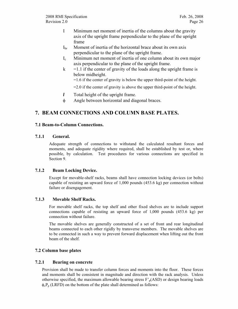
2008 RMI Specification Feb. 26, 2008 Revision 2.0 Page 26
I Minimum net moment of inertia of the columns about the gravity axis of the upright frame perpendicular to the plane of the upright frame
Ibr Moment of inertia of the horizontal brace about its own axis perpendicular to the plane of the upright frame.
Ic Minimum net moment of inertia of one column about its own major axis perpendicular to the plane of the upright frame.
k =1.1 if the center of gravity of the loads along the upright frame is below midheight.
=1.6 if the center of gravity is below the upper third-point of the height.
=2.0 if the center of gravity is above the upper third-point of the height.
l Total height of the upright frame. φ Angle between horizontal and diagonal braces.
7. BEAM CONNECTIONS AND COLUMN BASE PLATES.
7.1 Beam-to-Column Connections.
7.1.1 General. Adequate strength of connections to withstand the calculated resultant forces and moments, and adequate rigidity where required, shall be established by test or, where possible, by calculation. Test procedures for various connections are specified in Section 9.
7.1.2 Beam Locking Device. Except for movable-shelf racks, beams shall have connection locking devices (or bolts) capable of resisting an upward force of 1,000 pounds (453.6 kg) per connection without failure or disengagement.
7.1.3 Movable Shelf Racks. For movable shelf racks, the top shelf and other fixed shelves are to include support connections capable of resisting an upward force of 1,000 pounds (453.6 kg) per connection without failure.
The movable shelves are generally constructed of a set of front and rear longitudinal beams connected to each other rigidly by transverse members. The movable shelves are to be connected in such a way to prevent forward displacement when lifting out the front beam of the shelf.
7.2 Column base plates
7.2.1 Bearing on concrete Provision shall be made to transfer column forces and moments into the floor. These forces and moments shall be consistent in magnitude and direction with the rack analysis. Unless otherwise specified, the maximum allowable bearing stress F’p(ASD) or design bearing loads φcPp (LRFD) on the bottom of the plate shall determined as follows:
2008 RMI Specification Feb. 26, 2008 Revision 2.0 Page 27
for ASD
F fp c' . '= 0 7
for LRFD
P f Ap c Effective Base Bearing Area= 17. '
φc = 0.60
where f’c = the minimum 28-day compression strength of the concrete floor which, unless otherwise brought to the attention of the rack fabricator, shall be assumed to be 3,000 psi (2.1 x 10⁶ kg/m2).
7.2.2 Base plate design Once the required bearing area has been determined from the allowable bearing stress F’p the minimum thickness of the base plate is determined by rational analysis or by appropriate test using a test load 1.5 times the ASD design load or the factored LRFD load. Upon request, information shall be given to the owner, or the owner’s agent on the location, size, and pressures under the column base plates of each type of upright frame in the installation.
When rational analysis is used to determine base plate thickness, the base plate shall be designed for the following loading conditions, where applicable:
7.2.2.1 Downward vertical force. The effective area of the base plate is defined as the minimum area needed to satisfy the concrete bearing requirements or the minimum bearing area required by the concrete slab designer. This area may be the area bounded by the perimeter of the rack column, the full area of the base plate or some area in between these two values. The resulting area is defined as the effective base plate area. The base plate thickness shall be calculated assuming that the bearing pressure is uniformly distributed over the effective base plate area and the plate shall be analyzed as a rigid member.
7.2.2.2 Uplift/tension force When the base plate configuration uses a single anchor bolt and a net uplift force exists, the minimum base plate thickness shall be determined based on a design bending moment in the plate equal to the uplift force times 1/2 the distance from the centerline of the anchor to the nearest edge of the rack column. When the base plate configuration consists of two anchor bolts located on either side of the column and a net uplift force exists, the minimum base plate thickness shall be determined based on a design bending moment in the plate equal to the uplift force on one anchor times 1/2 the distance from the centerline of the anchor to the nearest edge of the rack column.
7.2.2.3 Axial load plus bending (down-aisle seismic or wind) When downward axial loads and bending moments due to lateral loads exist, the base plate thickness and anchor forces shall be determined as follows:
When e = M/P <= N/6, where N = effective length of the base plate in the down-aisle direction, no uplift of the base plate will occur. Therefore, no tension force will be present in the anchors and the anchors shall be designed for the maximum calculated shear force. The base plate thickness shall be determined as in Section 7.2.2.1.
2008 RMI Specification Feb. 26, 2008 Revision 2.0 Page 28
When e > N/6, where N = effective length of the base plate in the down-aisle direction, then a tension force may occur in the anchor(s). The tension force can be calculated directly once the compressive stress block underneath the plate has been established. In order to calculate the anchor tension, the designer must assume either the peak magnitude of the stress distribution or the length of the stress block. Once the concrete stress block distribution and magnitude has been established, the anchor tension can be calculated directly through the equations of equilibrium. The base plate thickness shall be determined as in Section 7.2.2.1.
Anchors shall be designed to resist the tensile and shear forces based on the anchor manufacturer's stated capacities and the resistance factors contained in Section 2 of this Specification.
7.2.3 Maximum Considered Earthquake Rotation The base connection shall have a rotational capacity not less than the rotational demand of the beam-to-column connection, ӨD.as calculated in Section 2.6.4. Otherwise, the base connection shall be considered pinned for the computation of the period and seismic displacement.
7.2.4 Shims Shims may be used under the base plate to maintain the plumbness of the storage rack. The shims shall be made of a material that meets or exceeds the design bearing strength (LRFD) or allowable bearing strength (ASD) of the floor. The shim size and location under the base plate shall be equal to or greater than the required base plate size and location
In no case shall the total thickness of any set of shims under a base plate exceed six times the diameter of the largest anchor bolt used in that base.
Shims that are a total thickness of less than or equal to six times the anchor bolt diameter under bases with less than two anchor bolts shall be interlocked or welded together in a fashion that is capable of transferring all the shear forces at the base.
Shims that are a total thickness of less than or equal to two times the anchor bolt diameter need not be interlocked or welded together.
8. SPECIAL RACK DESIGN PROVISIONS.
8.1 Overturning. Overturning is to be considered for the most unfavorable combination of vertical and horizontal loads. Stabilizing forces provided by the anchors to the floor are not considered in checking overturning, unless anchors and floor are specifically designed and installed to meet these uplift forces (Sections 2.5 and 2.6).
Unless all columns are so anchored, the ratio of the restoring moment to overturning moment shall not be less than 1.5.
The height-to-depth ratio of a storage rack shall not exceed 6 to 1 measured to the topmost beam position, unless the rack is anchored or braced externally to resist all forces.
Rack, which is loaded and unloaded by powered handling equipment, that exceed the 6 to 1 ratio defined above, shall also be designed to resist a 350 pound (159 kg) side force applied to any single frame at the top shelf level in a direction perpendicular to the aisle. For LRFD design method, the load factor applied to this force shall be 1.6. This force is to be applied to
2008 RMI Specification Feb. 26, 2008 Revision 2.0 Page 29
an empty frame and divided into as many frames as are interconnected in the direction of the force. Anchors and base plates will be designed to resist uplift forces from this force when applied to an empty frame. Frame columns need not be designed for the additional axial load from this force.
Unless it can be shown to be unnecessary because of such factors as soil, slab and frame stiffness, single rows of rack exceeding a height to depth ratio of 8 to 1 must be tied externally to the building or cross-aisle to another rack. Stabilizing a single rack with a height to depth ratio of over 8 to 1 with anchoring alone is not recommended unless designed and certified by an engineer.
The 350 pound (159 kg) side force in this section need not be applied concurrently with the horizontal forces of Sections 2.4, 2.5 or 2.6.
8.2 Connections to Buildings. Connections of racks to buildings, if any, shall be designed and installed to prevent reactions or displacements of the buildings from damaging the racks or the reactions or displacements of the racks from damaging the building (see also Section 1.4.10).
8.3 Interaction with Buildings. Storage rack located at levels above the ground level (as described in Section 2.6.2), rack buildings, or racks which depend upon attachments to buildings or other structures at other than floor level for their lateral stability, shall be designed to resist seismic forces that consider the responses of the building and storage rack to seismic ground motion and their interaction so as not to cause damage to one another.
8.4 PICK MODULES AND RACK SUPPORTED PLATFORMS Pick modules and rack supported platforms that are used by authorized or trained personnel and not open to the general public shall be designed in accordance with this section.
8.4.1 Posting of Design Loads The design loads for the floor areas of the rack supported platforms and pick module walkways shall be shown on the rack configuration and load application drawings. These design loads shall also be displayed in one or more conspicuous locations within the structure such as at the top of the access stairway.
8.4.2 Design Requirements Rack supported platforms and pick module walkways shall be designed for the maximum concentrated loads and the maximum uniformly distributed loads that are to be imposed on the rack supported platform floor. The owner shall advise the designer of the rack supported platform or pick module of all loads that are expected on the structure for its present or future use.
The design load for the foot traffic on pick module walkways shall be at least 60 psf live load superimposed over the entire area of the foot traffic walkway. Where applicable the pick module floor shall also be designed for conveyor leg loading, pallet staging, shelving, mobile-handling equipment or any other items that could cause additional load on the pick module walkway. In some cases conditions may require a higher design load. The user should advise the designer of all such conditions. The pick module walkway
2008 RMI Specification Feb. 26, 2008 Revision 2.0 Page 30
shall also be designed for other items such as lights or sprinkler pipes that may be hung from the pick module walkway floor or floor supports.
If the project specifications dictate that a pick module walkway live load greater than or equal to 100 psf is required and there are two or more floor levels, the live load may be reduced by 20 percent for the design of the column framing system which includes the support columns, the frame bracing, the frame bracing connections and the base plates. This reduction does not apply to the beams that support the floor or their connections.
The maximum live load deflection for beams that support rack supported platforms shall not be greater than L/240. The total load deflection shall not be more than L/180
The clear width of a pick module walkway shall be at least 30”.
8.4.3 Rack supported platform and Pick Module Walkway. Guardrails - Members that are installed on an elevated rack supported platform or pick module walkway whose purpose is to provide fall protection for the occupants of the structure. Guardrails consist of a top rail, an intermediate rail and posts.
Safety Flooring – A surface that is provided in areas where order picking personnel may need to step off the normal walking area or pick module walkway to dislodge loads that may not have properly flowed to their correct discharging positions.
Kick-plate – Kick-plates are vertical plates that extend upward at the edge of a floor surface to prevent loose items from sliding off the edge of the floor.
8.4.3.1 Guardrail Requirements. The horizontal top rail of the guardrail shall be 42” above the walking surface. Guardrails shall have a top rail and intermediate members such that a 21” sphere can not pass through below the top rail level. The ends of the rails shall not extend beyond the post except where extending the rails will not create a hazard. Where there is a discontinuity of the guardrail that exceeds 6” such as between vertical members or between stairs and a vertical member, filler guardrail is required to provide fall protection for this space. The top and intermediate guard rails or any other part of the guardrail assembly must be designed to resist the following loads applied separately (not simultaneously):
1. Concentrated live load of 200 pounds applied at any location along the top rail assembly in any direction.
2. Distributed live load of 20 plf applied in any direction along the length of any member that is part of the assembly.
Guardrails are not required to be in place where they would interfere with product being loaded into or removed from the pick module system. Guardrail must be provided to close any other openings through which an order picker may fall. Where guardrails are omitted for pallet drops, safety gates, removable guardrail sections or removable chains must be used for fall protection. These devices must meet the same strength and configuration requirements as the permanently installed guardrail.
8.4.3.2 Safety Flooring Requirements Safety flooring shall be designed for a 300# concentrated load (to support the picker) and a distributed live load of 60 psf acting separately. The pickers shall not walk out onto the safety flooring without observing the correct safety procedures that are required
2008 RMI Specification Feb. 26, 2008 Revision 2.0 Page 31
for the pick module use. The pickers shall stay at least 4 feet away from the open end of the safety flooring.
8.4.3.3 Kick-plate Requirements Kick-plates shall extend at least 4” above the floor surface. Kick-plates are not required at picking locations but are required at pallet drop locations. The user shall specify to the designer any additional areas where kick-plate may be needed for safety due to the configuration of the pick module.
8.4.3.4 Special Conditions Floor openings under the conveyor path that are used for the discharge of trash need not have guardrail or kick plates as this would interfere with the efficient discharge of trash.
Where conveyor inclines rise through an opening in the floor, guardrail is generally required on all sides except the side where use of such guardrail would interfere with the conveyor or product.
Kick-plates are not required where rack frame bracing or other structural components such as shelf decking or safety flooring are next to the edge of the floor.
Guardrails are not required at locations where other structural members such as rack frame horizontal members are provided that meet the strength and configuration requirements of the guardrail.
8.4.4 Stairways Fixed stairways shall be provided for access to elevated rack supported platforms or pick modules by authorized or trained personnel. Fixed stairways shall be designed and constructed to carry a load of 300 psf but shall not be of less strength than to carry a concentrated live load of 1000 lbs at any point along the stairway.[other reqmts may need to be considered]
Fixed stairways shall have a minimum tread width of 30”. A vertical clearance of seven feet shall be maintained between the stairway and any overhead obstruction measured from the leading edge of the tread. Stairways shall be installed at angles to the horizontal of between 30 and 50 degrees. The sum of the rise and the run of a single step should be approximately 17.5 inches with the minimum rise of 6.5 inches and a maximum rise of 9.5 inches.
Rise height and tread length shall be uniform throughout any flight of stairs including any foundation structure used as one or more of the treads of the stairs. Open risers are allowed.
Stairway landings shall be no less than the width of the stairway and a minimum of 30” in length measured in the direction of travel. Intermediate landings are required if vertical rise exceeds 12 ft.
Handrails shall be provided on both sides of all stairways. If the total rise of the stairway is less than 44” stair handrails are not required.
Stair Handrail – Smooth, continuous railing that runs up a stair rise assembly to provide added balance and safety for the occupants as they walk up or down the stair rise assembly.
Stair handrail shall be 30” to 34” in height when measured from the top of each tread at the face of the tread. Stair handrail brackets or posts supports shall be spaced at no more
2008 RMI Specification Feb. 26, 2008 Revision 2.0 Page 32
than 8 ft. centers and the rail shall be mounted so a clearance of at least 3” exists horizontally between the rail and any obstruction. Stair handrails shall be designed for the same forces as guardrails.
Stair handrail extensions are not required in pick module or rack supported platform stair assemblies.
8.4.5 Product Fall Protection The owner should specify to the designer any locations where operations may require horizontal or vertical safety barriers. These barriers shall prevent product from falling into those areas.
8.5 AUTOMATED STORAGE AND RETRIEVAL SYSTEMS (STACKER RACKS) Stacker racks may be “Load Arm and Rail Type” or “Beam Column Type” and can be used in “Rack Supported Systems”.
Shown in parenthesis in the heading are the numbers corresponding to parts of this Specification.
8.5.1 Tolerances (1.4.11) Installation and design tolerances shall be supplied by the user of the installation based on the requirements of the equipment manufacturer.
8.5.2 Vertical Impact Loads (2.3) The moving equipment manufacturer is responsible for supplying to the rack manufacturer information on maximum vertical static and dynamic loads for the design of racks; the rack structures shall be designed for these loads.
8.5.3 Horizontal Loads (2.4) Horizontal loads specified in Section 2.4.1 and 2.4.2 of the Specification shall be used in the design of racks.
8.5.4 Wind (2.5) and Snow Loads Wind (including uplift) and snow loads shall be considered in the design of rack during erection and use. In determining the total force on a rack structure, forces in all members of the structure shall be accounted for with proper consideration of shielding effects, the shape effect, and other applicable forces.
The forces specified in Section 2.4.1, 2.4.2 and 2.6 need not be assumed to act concurrently with wind loads.
8.5.5 Deflections (5.3) Deflections shall not exceed the limits set by the requirements of the equipment operation.
2008 RMI Specification Feb. 26, 2008 Revision 2.0 Page 33
8.5.6 Rack Compatibility with the Equipment Horizontal and vertical deflections shall be calculated and reviewed with the crane equipment supplier for compatibility.
Rack design shall be compatible with the equipment. The basic considerations shall include the height of the first shelf, clearance from the top shelf to the cross-aisle tie, shuttle window height, and sprinkler system.
9. TEST METHODS.
9.1 GENERAL. Material properties as determined in accordance with the applicable ASTM A370 test procedures and Section F3 of the AISI Specification apply. For this purpose, tensile coupons are taken, after the completion of testing, from flat portions of the specimen at regions of low bending moment and shear force.
If the effect of cold-work is being accounted for by test, the test specimens must be formed by the same procedure as is used or contemplated in the prototype. This is essential because different manufacturing methods produce different amounts of cold working (e.g., cold working of a specimen by press-braking is less than that in a cold-roll-formed prototype).
Test specimens are to be fully described prior to testing and any dents or defects shall be noted and the condition of welds, if any, inspected and described. All cross-sectional dimensions of each specimen are to be measured prior to testing at several points along the length and photographs of specimens should be taken prior to, during, and after testing whenever it seems advisable. (The purpose of these tests is for design and not for purchase acceptance-tests).
9.1.1 Testing Apparatus and Fixtures. These tests should be carried out in a testing machine or by means of hydraulic jacks in a test frame or by application of properly measured weights. The testing machine or load-measuring apparatus must meet the requirements prescribed in the ASTM Methods E4, Verification of Testing Machines.
The weights of load distribution beams and other fixtures are to be measured and included in evaluating the test data.
9.1.2 Instrumentation Dial gages or other deflection measuring devices are required at appropriate points to obtain proper alignment and to measure load-deflection behavior accurately. The deflections should be measured and reported to an accuracy of ±0.03 inches (0.76 mm).
Strain gages may be used if behavior characteristics other than ultimate loads and load-deflection relations are desired. In general, for coupon tests, extensometers are used.
For members subject to twisting (such as channel and Z sections), the twist angle shall be measured by proper means.
9.1.3 Reduction and Presentation of Test Data. For each test, the report is to include:
1. A sketch of the specimen with all dimensions.
2008 RMI Specification Feb. 26, 2008 Revision 2.0 Page 34
2. A sketch of the test set-up with all dimensions, including locations and kinds of gages, loading and support arrangements and an identification of the loading apparatus (testing machine, jacks, etc.) with information on the range used and the smallest increment readable for that range.
3. The results of the coupon tension tests should be presented in the form of a table of elongations vs. loads or, alternatively, strains vs. stresses. Yield stress and ultimate strength shall be determined by any of the accepted ASTM methods. (It is desirable to include stress-strain curves in the data presentation.)
4. For presentation of the results of the test, all load, deflection, and other recorded data shall be properly reduced to actual values by correcting, where appropriate, for initial readings, weights of loading apparatus (e.g., loading beams), etc.
These reduced measurements shall be presented in tables showing load vs. the particular measured quantity (deflection, strain, etc.) In the same tables, observations of special events (flange buckling, connection failure, etc.) shall be noted at the particular load at which they occurred.
Graphic presentation of load-deformation curves is advisable at least for the mid-span deflections depending upon observations made during the tests and on inspection of tabulated data, graphic presentation of selected or all other load-deformation data is desirable, but optional as dictated by judgment.
9.1.4 Evaluation of Tests for Determining Structural Performance.
Tests are to be evaluated in accordance with Sec. F1 of the AISI (2001) [1].
9.2 STUB COLUMN TESTS FOR COLD-FORMED AND HOT-ROLLED COLUMNS.
9.2.1 Test Specimen and Procedure. The Q values of perforated compression members for use in Section 4 are determined by stub column tests as described in Part VIII of the AISI Cold-Formed Steel Design Manual [4]. The ends of the stub column must be milled flat (preferably to a tolerance of ±0.001 inch [0.00254 mm]) and perpendicular to the longitudinal axis of the column. The axial load is to be applied by flat plates bearing (not welded or otherwise connected) against the milled ends. For the purposes of determining Q, only the ultimate strength of the stub column needs to be determined.
9.2.2 Evaluation of Test Results. Q is calculated as follows:
QF Ay
=ultimate compresive strength of stub column by test
net min
where
Fy = actual yield stress of the column material if no cold work effects are to be considered; or the weighted average yield to point Fy, calculated in accordance
2008 RMI Specification Feb. 26, 2008 Revision 2.0 Page 35
with appendix A 5.2.2 of the AISI (2001) [1], if cold work effects are to be considered.
Anet min = minimum cross-sectional area obtained by passing a plane through the column normal to the axis of the column. In no case shall Q be greater than 1.
Where a series of sections with identical cross-sectional dimensions and identical hole dimensions and locations is produced in a variety of thickness, stub column tests need be made only for the largest and the smallest thicknesses (tmax and tmin). Q values for intermediate thicknesses shall then be determined by interpolation according to the following formulas:
( )( )
( )Q = Q min +
− −
−
Q Q t tt t
max min min
max min
where Q is the value for the intermediate thickness t, and Qmax and Qmin are the values obtained by test for the largest and smallest thicknesses, respectively. This interpolation is permissible only if the yield stresses of the two specimens do not differ by more than 25 percent and if the yield points of the intermediate thicknesses fall between or below those of the test specimens.
9.3 PALLET BEAM TESTS.
9.3.1 Simply Supported Pallet Beam Tests. These tests are acceptable only for beams that are not subject to significant torsional stresses or distortions.
The simply supported pallet beam test is to be made only if the flexural behavior parameters such as the yield moment, ultimate moment and the effective flexural rigidity (EI) are to be determined. For the latter parameter, tests are to be conducted on two identical specimens unless a third test is required as specified in Section 9.3.1.3. If lateral restraints are required, the beams are to be tested in pairs as they would be used in completed assemblies.
9.3.1.1 Test Setup. The test set-up consists of a beam test specimen simply supported at each end (not connected to columns). The test load is applied to a load distribution beam which in turn imposes a load at two points on the beam which in turn imposes a load at two points on the beam specimen. Each load point on the beam test specimen is set at a distance of S/C from the support; where S is the span and C is a numerical value between 2.5 and 3. Plates can be used to prevent local failure at supports or at load points.
9.3.1.2 Test Procedure. After alignment, a small initial load of about 5% of the expected ultimate test load shall be applied to the test assembly to ensure firm contact between the specimen and all loading and support components. At this load, initial readings are to be taken from all gages. Loads shall then be applied in increments no larger than about one-fifth of the expected design load. Readings are taken for all load increments. (It is good to plot load verses mid-span deflection readings at each load increment during testing). Noticeable deviation from straightness of such a plot will indicate incipient inelastic behavior or
2008 RMI Specification Feb. 26, 2008 Revision 2.0 Page 36
local buckling or crippling. When such is the case, load increments are reduced to no more than half the initial increments.(It is good practice, though not required, to measure permanent set for loads within the interval of ±25% of the expected design load by reducing, within this interval, the ratio of the applied load to the initial load after the increment. Appropriate gage readings are to be taken at this reduced load to determine permanent set).
When deflection increments for given load increments increase rapidly, this indicates the approach of ultimate failure load. If sudden failure is possible by the nature of the specimen, and if such sudden failure could damage the gages, they should be removed. On the other hand, if a gradual failure is expected, such as by simply yielding, it is desirable to measure the last center line deflections right up to and past the maximum or ultimate load, to obtain some part of the descending portion of the load deflection curve.
All specific events noticeable by visual inspection, such as local buckling, crippling, failure of connections, etc., are to be recorded at the loads at which they occur.
9.3.1.3 Evaluation of Test Results. The parameters investigated shall be determined by test results by conventional methods.
The flexural rigidity shall be calculated on the basis of the results of two tests of identical specimens, provided that the deviation from the average value does not exceed 10%. If the deviation from the average exceeds 10%, then a third identical specimen is to be tested. The average of the two lower values obtained from the tests shall be the result from the series of tests.
9.3.2 Pallet Beam in Upright Frames Assembly Test. This test is intended to simulate the conditions in the actual rack as closely as possible.
9.3.2.1 Test Setup. The test assembly shall consist of two upright frames not bolted to the floor and two levels of pallet beams with front-to-back ties when specified.
The upright frame may be as high as desired. However, the bottom level beams shall be tested and shall be located so there will not be less than 24 inches (61 cm) clear between the test beams and the floor or between the test beams and the top-level beams.
The end connections shall be those used in the prototype.
The location of the test loads perpendicular to the beams shall simulate actual loading.
If loads are to be applied by pallets or other devices resting on beams, it is important that friction between pallet and beams be reduced to the minimum possible amount by greasing or other means. (This is suggested because new, dry pallets on new, dry beams when used in the test could provide considerably more bracing than pallets and beams worn smooth in use and possibly covered with a film of oil.)
The minimum instrumentation for such tests consists of devices for measuring the deflections of both beams at mid-span relative to the ends of the beams. One way of doing this is to attach a scale graduated to 0.01 inch (0.0254 mm) at mid-span of each beam and to stretch a tight string (usually a string with a rubber band at one end) or wire attached to each end of the beam. Another way is to use dial gages at mid-span and at each end of the beams. Transits may also be used to read scales located at mid-span and at the end of the beams.
2008 RMI Specification Feb. 26, 2008 Revision 2.0 Page 37
Additional instrumentation, such as strain gages or additional dial gages at the ends of the beam, is needed only if special problems are to be considered. For highly unsymmetrical beams, e.g., deep channels or C-sections, it may be advisable to measure rotation under load. This is most easily done by rigidly attaching a protractor of sufficient size to the beam at or close to mid-span. A vertical string weighted at the end and acting as a plumb is then read against the protractor at every load increment.
9.3.2.2 Test Procedure. The test procedures specified in Section 9.3.1.2 of this report shall be used.
9.3.2.3 Evaluation of Test Results. The design load shall be the smallest of the following:
1. Strength determined according to the applicable provisions of the AISI (2001) [1] Section F and its subsections.
2. Two-thirds of the load at which harmful or objectionable distortions are observed in the connections or elsewhere. These distortions include rotations of such magnitude as to render the beam unserviceable.
3. The load (not including impact) at which maximum vertical deflections attain 1/180 of the span, measured with respect to the ends of the beams.
9.3.2.4 Number of Tests Required The number of tests for determining design loads shall be as specified in Section F of the AISI (2001) [1].
9.3.2.5 Deflection Test Once the design load has been determined as specified in Sections 9.3.1 through 9.3.2.3, an additional test shall be made using a new set of specimens. An initial load equal to the design load shall be applied, reduced to zero and the deflection read; this deflection reading shall be the zero reference reading. A load equal to 1.5 times the design load shall then be applied and the deflection read. The load shall then be held constant for one-quarter of an hour and the deflection read again. This deflection reading shall not exceed the previous reading by more than 5 percent. The load shall then be reduced to zero and the residual or permanent deflection read. The net residual deflection of the beam shall not exceed 15 percent of the final deflection measured at 1.5 times the design load. If these limitations are not met, the design load shall be reduced accordingly or the source of residual deflections determined and remedied, and the test repeated with new specimens.
9.4 PALLET BEAM-TO-COLUMN CONNECTION TESTS.
9.4.1 The Cantilever Test. This test is for determining the connection moment capacity.
9.4.1.1 Test Setup. The test setup shall consist of a pallet beam at least 26 inches (66 mm) in length connected to the center of a column at least 30 inches (76 cm) in length. Both ends of the
2008 RMI Specification Feb. 26, 2008 Revision 2.0 Page 38
column shall be rigidly connected to rigid supports. The load shall be applied to the pallet beam at 24 inches (61 cm) from the face of the column. At this load application point, a dial gage shall be mounted to measure deflections.
9.4.1.2 Test Procedure. The test procedure specified in Section 9.3.1.2 shall be used.
9.4.1.3 Evaluation of Test Results. The design moment shall be determined in a manner similar to that specified in provisions 1 and 2 of Section 9.3.2.3.
9.4.2 The Portal Test. This test is be used to obtain a joint spring constant needed for a semi-rigid frame analysis.
9.4.2.1 Test Setup. The test setup shall consist of two upright frames supported on four half-round bars, one under the base of each column, two beams the top of which is installed at a distance of 24 inches (61 cm) from the floor, and including front-to-back ties when specified. The half-round bars shall be located at the centroidal axes of the columns perpendicular to the beams. Extra plates may be placed between the base plates and the half-round bars, if necessary. The bases of the columns shall be held against lateral displacement but not against rotation.
9.4.2.2 Test Procedure. After the rack is properly assembled, a load equal to the design load of the beams shall be placed on the beams, simulating usual loading. A horizontal force equal to the horizontal design load corresponding to the vertical load on the assembly shall be applied to the assembly, equally distributed between the two columns on one side, at the level of the top of the beams, and in the direction of the beams. Deflection due to the horizontal loading shall be measured at the level of the top of the beams.
The procedure shall be repeated at a load twice the design load.
9.4.2.3 Evaluation of Test Results. The spring constant is to be determined by rational analysis.
9.5 UPRIGHT FRAME TEST. The frame tests specified in this section are intended to simulate the conditions in the actual rack as closely as possible. The purpose of the test is to determine the upright frame loads for an expected column failure that takes place between the floor and the bottom beam or between the two lower beams in a three beam-level test setup.
The test will account for vertical and horizontal loads as specified in Section 2.4.1 as well as the effects of semi-rigid connections. This procedure is also applicable to Section 2.5 and 2.6 with adjustments to take into account modified loads and increased allowable stresses for Allowable Stress Design.
2008 RMI Specification Feb. 26, 2008 Revision 2.0 Page 39
9.5.1 Horizontal Load in the Direction Perpendicular to the Upright Frame.
9.5.1.1 Symmetrical Loading Condition.
9.5.1.1.1 Test Setup. The test assembly shall consist of three upright frames not bolted to the floor, and at least two levels of beams connecting the frames together to make two bays of pallet rack. When the distance from the floor to the first beam is smaller than the distance between beams, then three levels of beams shall be used.
The vertical spacing of the beams shall be the same as in the actual application. The upright frame may be as high as desired; however, its construction consisting of a column and truss web members shall be of the same cross section, pattern and spacing as in the actual application. The top beam level and its column connection may be heavier or reinforced to the degree necessary to carry the test load to the point where the frame fails. The remaining beams and their connections shall be as in the actual application. This test load represents the loading from two or more beam levels.
Horizontal loads shall be applied perpendicular to one outside upright frame at the centerline of the beam connection by means of either hydraulic cylinder(s) or by ropes and pulleys with hanging weights attached. The load at each beam level shall be applied equally to each column of the upright frame.
To measure horizontal displacements, one scale shall be located at the centerline of each beam level, and another scale at midheight between the bottom beam level and the floor. All scales may be placed on one column.
9.5.1.1.2 Test Procedure. 1. Align the rack structure so that it is level and plumb and so that all components are
properly seated.
2. Take initial scale readings.
3. Place a vertical load equal to 1.5 times beam design load on each of the lower beam levels.
4. Take scale readings for horizontal movement.
5. Apply a horizontal load to the upright frame at each beam level. The horizontal load shall be determined per Section 2.4.1.
6. Take scale readings for horizontal movement.
7. Apply one additional unit of vertical load to the reinforced top level beams only and take scale readings for horizontal movement.
8. Apply one additional unit of horizontal load to the reinforced top level beams only. Take scale readings for horizontal movement. (If hydraulic cylinders are used, be sure the hydraulic cylinder at the bottom beam level is always applying the proper force to the upright frame.)
9. Repeat steps (7) and (8) until failure occurs in the upright frame.
9.5.1.1.3 Evaluation of Test Results. The vertical design load for an upright frame shall be determined according to the applicable provisions of the AISI (2001) [1] Section F and its subsections. The tested
2008 RMI Specification Feb. 26, 2008 Revision 2.0 Page 40
ultimate load must be the last set of test data which has an equal number of both vertical and horizontal load increments. The tested ultimate load should be the lowest of the three tested conditions, namely symmetrical loading in Section 9.5.1.1, unsymmetrical loading in Section 9.5.1.2, or for the horizontal load in the direction parallel to the upright frame.
9.5.1.2 Unsymmetrical Loading Condition. Test setup and test procedure are the same as Section 9.5.1.1 for symmetrical loading condition above, except that no load should be placed on one beam level in one bay directly adjacent to the expected column failure location. The direction of the horizontal load should be in the direction of sidesway.
9.5.2 Horizontal Load in the Direction Parallel to the Plane of Upright Frame.
9.5.2.1 Test Setup. The test setup is the same as in Section 9.5.1.1.1, except that the locations of horizontal loads and scales shall be changed so that the horizontal loads and displacements are in the plane of the upright frame.
9.5.2.2 Test Procedure. The test procedure is the same as the procedure in Section 9.5.1.1.2 above, except in step (5) the distribution of the horizontal load on each beam level on each upright frame shall be as determined in Section 2.4.1.
In order to compensate for the effect of the longer moment arm of the upper beam levels in the actual application, the applied test loads shall be modified such that the effect of the loads in the upper beam levels of the rack are properly accounted for both in overturning and shear force.
9.5.2.3 Evaluation of Test Results. See Section 9.5.1.1.3.
9.6 CYCLIC TESTING OF BEAM-TO-COLUMN CONNECTIONS
9.6.1 General This protocol includes requirements for qualifying cyclic tests of beam-to-column moment connections in steel storage rack beam-to-column connectors. The purpose of the testing described in this document is to provide evidence that a beam-to-column connection satisfies the requirements for Strength and Drift Angle comparable to those stated in the AISC Provisions. Alternate testing requirements are permitted when approved by the Engineer of Record and the Authority Having Jurisdiction. It is also the purpose of this series of tests to determine the moment-rotation characteristics, or “dynamic spring relationship” of the beam-to-column connections of the various designs and manufacturers.
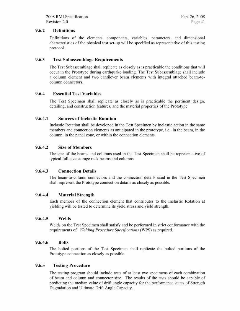
2008 RMI Specification Feb. 26, 2008 Revision 2.0 Page 41
9.6.2 Definitions Definitions of the elements, components, variables, parameters, and dimensional characteristics of the physical test set-up will be specified as representative of this testing protocol.
9.6.3 Test Subassemblage Requirements The Test Subassemblage shall replicate as closely as is practicable the conditions that will occur in the Prototype during earthquake loading. The Test Subassemblage shall include a column element and two cantilever beam elements with integral attached beam-to-column connectors.
9.6.4 Essential Test Variables The Test Specimen shall replicate as closely as is practicable the pertinent design, detailing, and construction features, and the material properties of the Prototype.
9.6.4.1 Sources of Inelastic Rotation Inelastic Rotation shall be developed in the Test Specimen by inelastic action in the same members and connection elements as anticipated in the prototype, i.e., in the beam, in the column, in the panel zone, or within the connection elements.
9.6.4.2 Size of Members The size of the beams and columns used in the Test Specimen shall be representative of typical full-size storage rack beams and columns.
9.6.4.3 Connection Details The beam-to-column connectors and the connection details used in the Test Specimen shall represent the Prototype connection details as closely as possible.
9.6.4.4 Material Strength Each member of the connection element that contributes to the Inelastic Rotation at yielding will be tested to determine its yield stress and yield strength.
9.6.4.5 Welds Welds on the Test Specimen shall satisfy and be performed in strict conformance with the requirements of Welding Procedure Specifications (WPS) as required.
9.6.4.6 Bolts The bolted portions of the Test Specimen shall replicate the bolted portions of the Prototype connection as closely as possible.
9.6.5 Testing Procedure The testing program should include tests of at least two specimens of each combination of beam and column and connector size. The results of the tests should be capable of predicting the median value of drift angle capacity for the performance states of Strength Degradation and Ultimate Drift Angle Capacity.
2008 RMI Specification Feb. 26, 2008 Revision 2.0 Page 42
Figure 9.6.5-1 Test Set Up
9.6.6 Loading History-General Requirements Prior to the application of any cyclic loading, a constant downward load, Pc, of one kip shall be applied to each beam segment adjacent to each connector on both sides of the beam-to-column connection simulating the design downward-acting gravity pallet loads that serve to fully engage the beams and their connectors into the columns receiving them.
The Test Specimen shall be subjected to cyclic loads according to the requirements prescribed for beam-to-column moment connections in Moment Frames. Other loading sequences may be used when they are demonstrated to be of equivalent or greater severity. Qualifying tests shall be conducted by controlling the Peak Drift Angle imposed on the Test Specimen.
Loading will proceed with the application of equal displacements at each end of each beam, and the measurement of the force corresponding to each such displacement.
9.6.7 Instrumentation Sufficient instrumentation shall be provided on the Test Specimen to permit measurement or calculation of the quantities required to produce meaningful, reproducible results for this testing protocol.
9.6.8 Material Testing Requirements
9.6.8.1 Tension Testing Requirements Tension testing shall be conducted on samples of steel taken from the material adjacent to each Test Specimen. Tension-test results from certified mill test reports shall be reported but are not permitted to be used in place of specimen testing for the purposes of this Section
9.6.8.2 Methods of Tension Testing Tension-test results shall be based upon testing that is conducted in accordance with the appropriate ASTM testing protocols for the particular materials being used.
2008 RMI Specification Feb. 26, 2008 Revision 2.0 Page 43
9.6.9 Test Reporting Requirements For each Test Specimen, a written test report meeting the requirements of the Authority Having Jurisdiction and the requirements of this Section shall be prepared. The report shall thoroughly document all key features and results of the test. Additional drawings, data, photographs, and discussion of the Test Specimen or test results are permitted to be included in the report.
9.6.10 Acceptance Criteria The Test Specimen must satisfy the Strength and Drift Angle requirements of this protocol for the connection, as applicable. The Test Specimen must sustain the required Drift Angle for at least one complete loading cycle. The test results will also include the beam-to-column moment-rotation characteristics and “dynamic spring relationship” for each of the combinations tested.
2008 RMI Specification Feb. 26, 2008 Revision 2.0 Page 44
10. REFERENCES TO THE TEXT
1. American Iron and Steel Institute (AISI) (2001), North American Specification for the Design of Cold-Formed Steel Structural Members, Washington, DC.
2. American Institute of Steel Construction (AISC) (2005), Specification for Structural Steel Buildings, ANSI/AISC 360-05, Chicago, IL
3. American Iron and Steel Institute (AISI) (1996), Cold-Formed Steel Design Manual, Washington, DC.
4. Federal Emergency Management Agency (FEMA) (2005), Seismic Considerations for Steel Storage Racks Located in Areas Accessible to the Public, FEMA 460, FEMA, Washington, DC
5. American Society of Civil Engineers (ASCE) (2005), Minimum Design Loads for Buildings and Other Structures, SEI/ASCE 7-05, ASCE, Reston, VA.