Embed Size (px)
Citation preview
www.rkeducation.co.uk solutions for teaching and learning
RKSB Carmen Page 1
RKSB Carmen Shield Base PCB Component List and
Instructions
Constructed PCB PCB layout
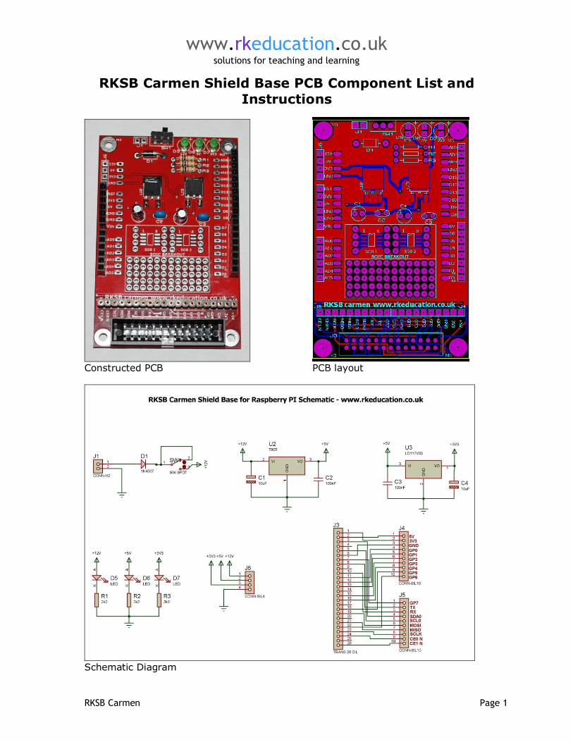
Schematic Diagram

www.rkeducation.co.uk solutions for teaching and learning
RKSB Carmen Page 2
Description RKSB Carmen Shield Base Project Board for Raspberry PI & Atmel
A low cost and simple method of interfacing Raspberry PI projects to Arduino shields
Interfaces to a Raspberry PI via a ribbon cable The user makes connections between the Raspberry PI and Arduino using
jumper wires
The Arduino shield then is pushed onto the headers Includes a 26 way dual row breakout header for interfacing to Raspberry PI Includes a power supply circuit with TO252 7805 and LD1117V33 regulators The power supply outputs are broken out at J6 Manufactured using a double sided professional red PCB Incorporates a small prototype area with plated through holes
Includes 2x SO8 breakouts An excellent method of interfacing Raspberry PI projects to Arduino shields
Component List C1, C4- 10uF 16VDC electrolytic capacitor C2, C3 – 100nF multilayer ceramic capacitor D5, D6, D7 - 3mm LEDs R1, R2, R3 – 1K ¼ watt resistor (brown black red) SW1 - ultra miniature slide switch U2 - TO252 7805 voltage regulator U3 - TO252 LD1117V33 voltage regulator
Various headers Instructions This PCB has been designed to interface the Raspberry PI with Arduino shields, for information on how to use shields please visit an appropriate website such as the Arduino forum.
When constructing PCBs it is advisable to start with the components with the lowest profile, for example the voltage regulators. Power should be supplied through J1 and 9-12VDC should be used, the terminal nearest SW1 is the positive supply. The diode D1 will reduce the voltage by approx. 0.7VDC, if required the diode D1 can be replaced with a shorting link. Make connections between J5 and the shield using wire links. There are 2x SOIC headers and a small prototype area. The power supply outputs are available at J6. The Raspberry PI is broken out at J4, study the schematic for exact details. A ribbon cable should be used. Shields can be pushed onto the circuit in order to be interfaced to the Raspberry PI.

www.rkeducation.co.uk solutions for teaching and learning
RKSB Carmen Page 3
Please visit our website
www.rkeducation.co.uk
If you have any comments or queries please email us at

www.rkeducation.co.uk solutions for teaching and learning
RKSB Carmen Page 4